

International comfort products PHN524, PHN548, PHN560, PHN536 Installation Instructions Manual
Installation Instructions
PHN5 Series
Single Phase
PACKAGED HEAT PUMP UNITS
TABLE OF CONTENTS
PAG E...............................................
SAFETY CONSIDERATIONS 1.......................
INTRODUCTION 2..................................
RECEIVING AND INSTALLATION 2...................
Check Equipment 2................................
Provide Unit Suppor 2..............................
Ground Level Installation 2.........................
Rooftop Installation 2..............................
Roof Curb 3......................................
Provide Clearances 3..............................
Rig and Place Unit 3...............................
Inspection 3......................................
Use of Rigging Bracket 3..........................
Select and Install Ductwork 7.......................
Converting Horizontal Discharge Units to Downflow
(Vertical) Discharge Units 9........................
Connect Condensate Drain 9.......................
Install Electrical Connections 9......................
High--Voltage Connections 10.....................
Special Procedures for 208--V Operation 10.........
Control Voltage Connections 10....................
Standard Connections 10.........................
Transformer Protection 10........................
Accessory Electric heaters Installation 10...........
Sequence of Operation 11.........................
PRE--START--UP 14.................................
START--UP 14......................................
Checking Cooling & Heating Control Operation 14....
Check for Refrigerant Leaks 14......................
Start--Up Adjustments 15..........................
Checking & Adjusting Refrigerant Charge 15........
Indoor Airflow & Airflow Adjustments 15.............
Continuous Fan Operation 16.....................
Defrost Control 17.................................
Quiet Shift 17...................................
Defrost 17......................................
MAINTENANCE 17.................................
Air Filter 18.......................................
Indoor Blower and Motor 18.........................
Outdoor Coil, Indoor Coil, & Condensate Drain Pan 20.
Outdoor Fan 21...................................
Electrical Controls and Wiring 21....................
Refrigerant Circuit 21..............................
Indoor Airflow 21..................................
Metering Devices-- TXV & Piston 22.................
Pressure Switches 22..............................
Loss of Charge Switch 22..........................
High Pressure Switch 22...........................
Copeland Scroll compressor (R--410A Refrigerant) 22..
Refrigerant System 22.............................
Refrigerant 22...................................
Compressor Oil 23
Servicing on Roofs with Synthetic Materials 23.......
Liquid Line Filter Drier 23.........................
R--410A Refrigerant Charging 23...................
System Information 23.............................
Loss of Charge Switch 23.........................
Check Defrost Thermostat 23.....................
...............................
Printed in U.S.A.
R--410A QUICK REFERENCE GUIDE 24..............
TROUBLESHOOTING 25............................
START--UP CHECKLIST 26..........................
International Comfort Products, LLC
Lewisburg, TN. 37091
518 01 2101 00 04--02--08
SAFE INSTALLATION REQUIREMENTS
We require these instructions as a minimum for a safe
installation.
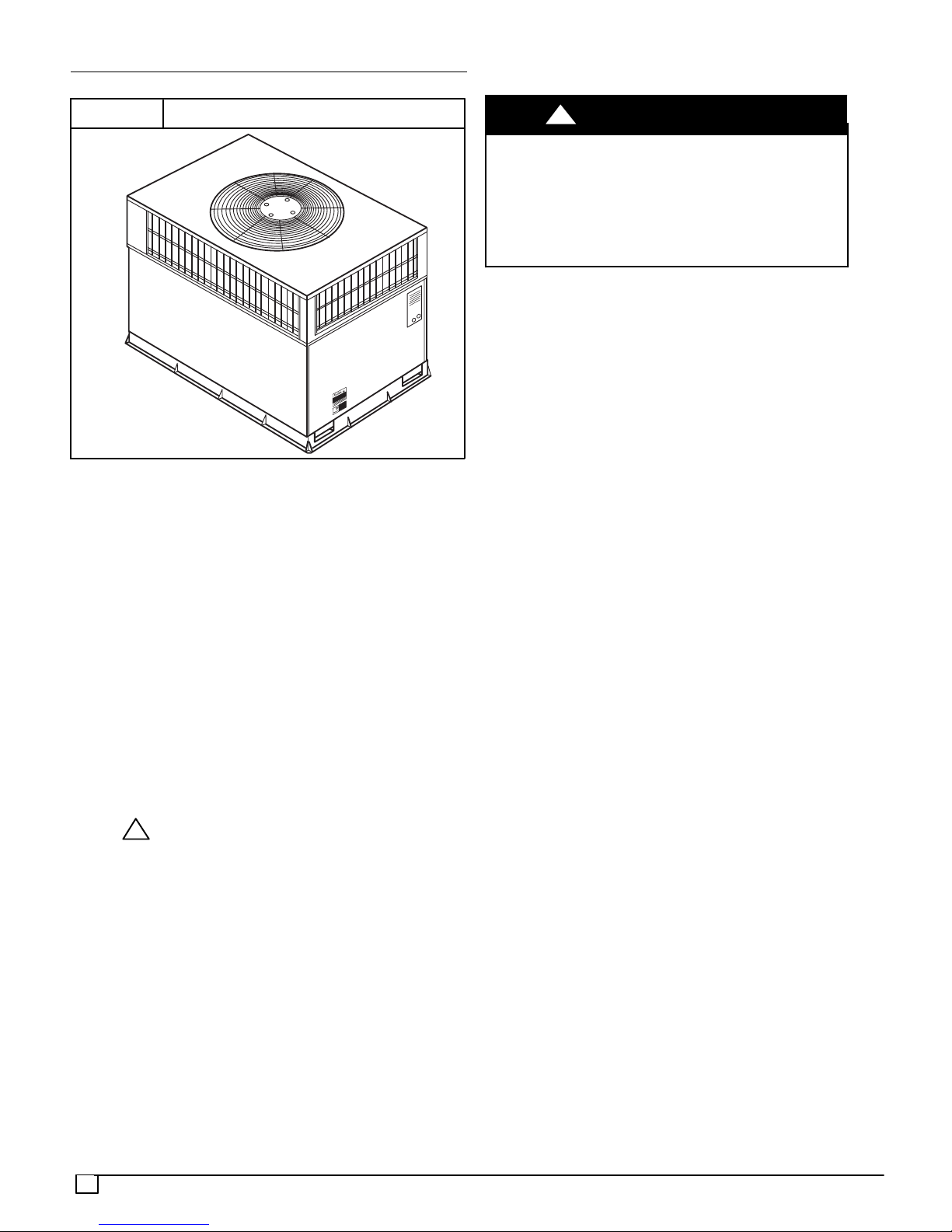
FIGURE 1
Installation and servicing of this equipment can be
hazardous due to mechanical and electrical components.
Only trained and qualified personnel should install, repair,
or service this equipment.
Untrained personnel can perform basic maintenance
functions such as cleaning and replacing air filters. All other
operations must be performed by trained service
personnel. When working on this equipment, observe
precautions in the literature, ontags, and on labels attached
to or shipped with the unit and other safety precautions that
may apply.
Follow all safety codes. Installation must be in compliance
with local and national building codes. Wear safety glasses,
protective clothing, and work gloves. Have fire extinguisher
available. Read these instructions thoroughly and follow all
warnings or cautions included in literature and attached to
the unit.
Recognize safety information. This is the safety--alert
symbol . When you see this symbol in instructions or
manuals, be alert to the potential for personal injury.
Understand the signal words DANGER, WARNING,
CAUTION, and NOTE. These words are used with the
safety--alert symbol. DANGER identifies the most serious
hazards which will result in serious injury or death.
WARNING signifies a hazard which could result in serious
injury or death. CAUTION is used to identify unsafe
practices which may result in minor personal injury or
product and property damage. NOTE is used to highlight
suggestions which will result in enhanced installation,
reliability, or operation.
These instructions cover minimum requirements and
conform to existing national standards and safety codes. In
some instances, these instructions exceed certain local
codes and ordinances, especially those that may not have
kept up with changing residential construction practices.
!
PHN5 HEAT PUMP UNIT
!
ELECTRICAL SHOCK HAZARD
Failure to follow this warning could result in personal
injury or death.
Before installing or servicing system, turn off power
supply to the unit and install lockout tag. There may be
more than one disconnect switch. Turn off accessory
heater power switch if applicable.
INTRODUCTION
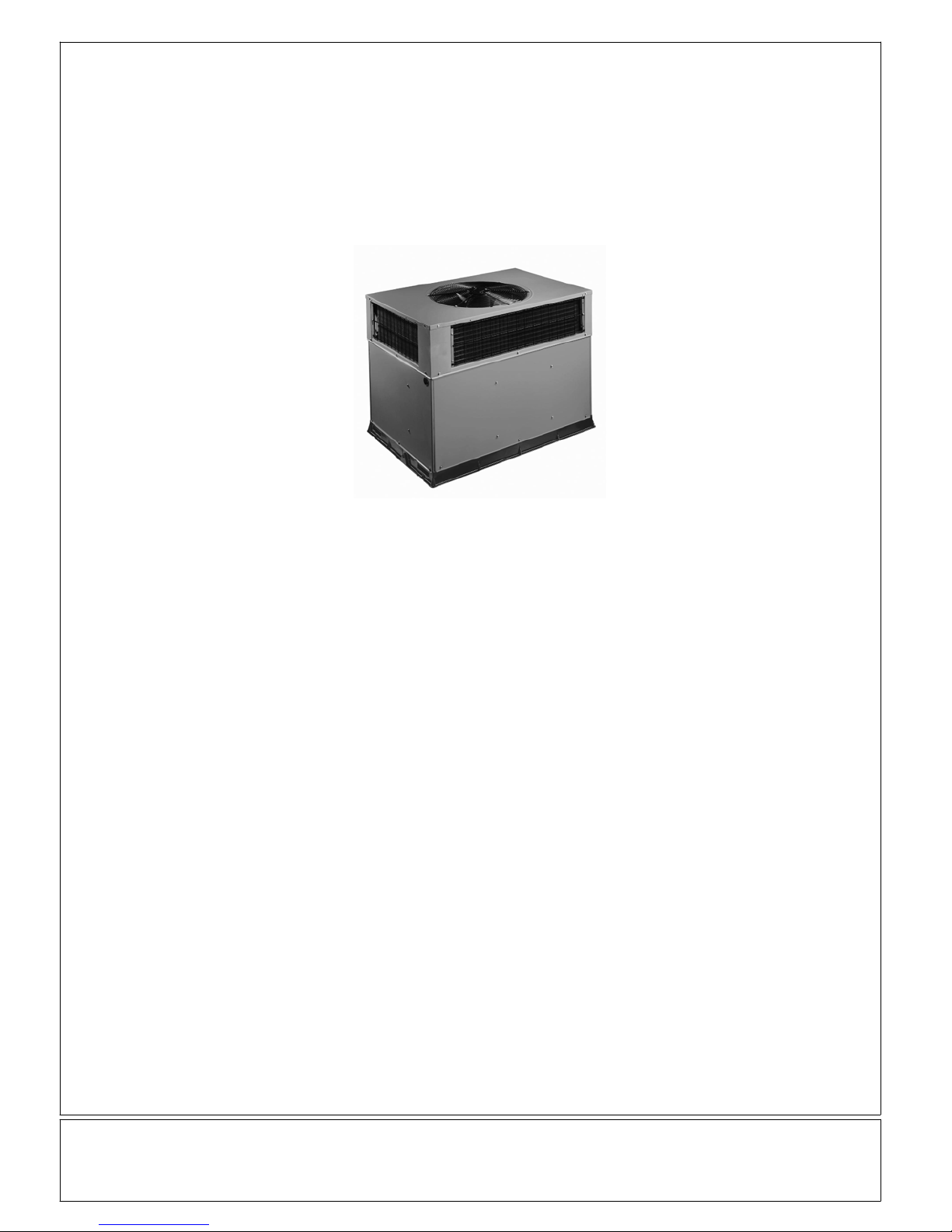
This packaged heat pump unit is fully self--contained and
designed for outdoor installation (see Fig. 1). See Fig. 3 and
4 for unit dimensions. All unit sizes have discharge
openings for both horizontal and downflow configurations
and are factory shipped with all downflow duct openings
covered. The unit may be installed e ither on a rooftop or at
ground level.
Step 1—Check Equipment
IDENTIFY UNIT
The unit model number and serial number are stamped on
the unit information plate. Check this information against
shipping papers.
INSPECT SHIPMENT
Inspect for shipping damage while unit is still on shipping
pallet. If unit appears to be damaged or is torn loose from
its anchorage, have it examined by transportation
inspectors before removal. Forward claim papers directlyto
transportation company. Manufacturer is not responsible
for any damage incurred in transit. Check all items against
shipping list. Immediately notify the nearest equipment
distribution office if any item is missing. To prevent loss or
damage, leave all parts in original packages until
installation.
Step 2—Provide Unit Support
Ground Level Installation
Ground level platform requirements:
-- The unit MUST be situated to provide safe access for
servicing.
-- The unit must be level and supported above grade by
beams, platform, or a pad. Platform or pad can b e of
open or solid construction but should be of permanent
materials such as concrete, bricks, blocks, steel, or
pressure--treated timbers approved for ground contact.
Soil conditions must be considered so that the platform
or pad does not shift or settle and leave the unit partially
supported.
-- Position platform separate from building foundation.
-- Install in well--drained area, with top surface of platform
above grade level.
-- Platform must be high enough to allow for proper
condensate trap installation and drainage
Rooftop Installation
Rooftop platform requirements:
WARNING
RECEIVING AND INSTALLATION
2
-- The unit MUST be situated to provide safe access for
servicing.
-- The existing roof structure MUST be adequate to
support the weight of the unit or the roof MUST be
reinforced.
Check the weight of the unit in relation to the roof
structure and local building codes or ordinances and
reinforce roof structure if necessary. See Figures 3 and
4 of this manual for unit weights.
-- Support for the unit MUST be level and strong enough
to carry unit weight. The support may consist of a
platform or a combination of platform and roof beams or
curb.
-- S e e Hoisting section for hoisting instructions.
For hurricane tie downs, contact distributor for details and
PE (Professional Engineering) Certificate if required.
ROOFCURB
Install accessory roof curb in accordance with instructions
shipped with curb. Install insulation,cant strips, roofing, and
flashing. Ductwork must be attached to curb.
equipment, and any other safety precautions that might
apply.
Training for operators of the lifting equipment should
include, but not be limited to, the following:
1. Application of the lifter to the load, and adjustment of
the lifts to adapt to various sizes or kinds of loads.
2. Instruction in any special operation or precaution.
3. Condition of the load as it relates to operation of the
lifting kit, such as balance, temperature, etc.
Follow all applicable safety codes. Wear safety shoes and
work gloves.
INSPECTION
Prior to initial use, and at monthly intervals, all rigging
brackets and straps should be visually inspected for any
damage, evidence of wear, structural deformation, or
cracks. Particular attention should be paid to excessive
wear at hoist hooking points and load support areas.
Brackets or straps showing any kind of wear in these areas
must not be used and should be discarded.
IMPORT ANT: The gasketing of the unit to the roof curb is
critical for a water tight seal. Install gasketing material
supplied with the roof curb. Improperly applied gasketing
also can result in air leaks and poor unit performance.
Curb should be level to within 1/4 in. (6mm). This is
necessary for unit drain to function properly. Refer to
accessory roof curb installation instructions for additional
information as required.
Step 3—Provide Clearances
The required minimumservice clearances areshown in Fig.
3 and 4. Adequate ventilation and outdoor air must be
provided. The outdoorfan draws air through the outdoor coil
and discharges it through the top fan grille. Be sure that the
fan discharge doesnot recirculate tothe outdoor coil.Do not
locate the unit in either a corner or under an overhead
obstruction. The minimum clearance under a partial
overhang (such as a normal house overhang) is 48 in.
(1219mm) above the unit top. The maximum horizontal
extension of a partial overhang must not exceed 48
in.(1219mm).
IMPORT ANT: Do not restrict outdoor airflow. An air
restriction at either the outdoor--air inlet or the fan discharge
may be detrimental to compressor life.
Do not place the unit where water, ice, or snow from an
overhang or roof will damage or flood the unit. Do not install
the unit on carpeting or other combustible materials.
Slab--mounted units should be at least 4 in. (102mm) above
the highest expected water and runoff levels. Do not use
unit if it has been under water.
Step 4—Rig and Place Unit
Rigging and handling of this equipment can be hazardous
for many reasons due to the installation location (roofs,
elevated structures, etc.).
Only trained, qualified crane operators and ground support
staff should handle and install this equipment.
When working with this equipment, observe precautions in
the literature, on tags, stickers, and labels attached to the
!
ELECTRICAL SHOCK HAZARD
Failure to follow this warning could result in personal
injury or death.
Before installing or servicing system, always turn off
main power to system. There may be more than one
disconnect switch. Turn off accessory heater power
switch if applicable. Tag disconnect switch with a suitable
warning label.
!
UNIT FALLING HAZARD
Failure to follow this warning could result in personal
injury or death.
Never stand beneath rigged units or lift over people.
!
PROPERTY DAMAGE HAZARD
Failure to follow this warning could result in personal
injury/death or property damage.
Rigging brackets for one unit use only . When
removing a unit at the end of its useful life, use a new set
of brackets.
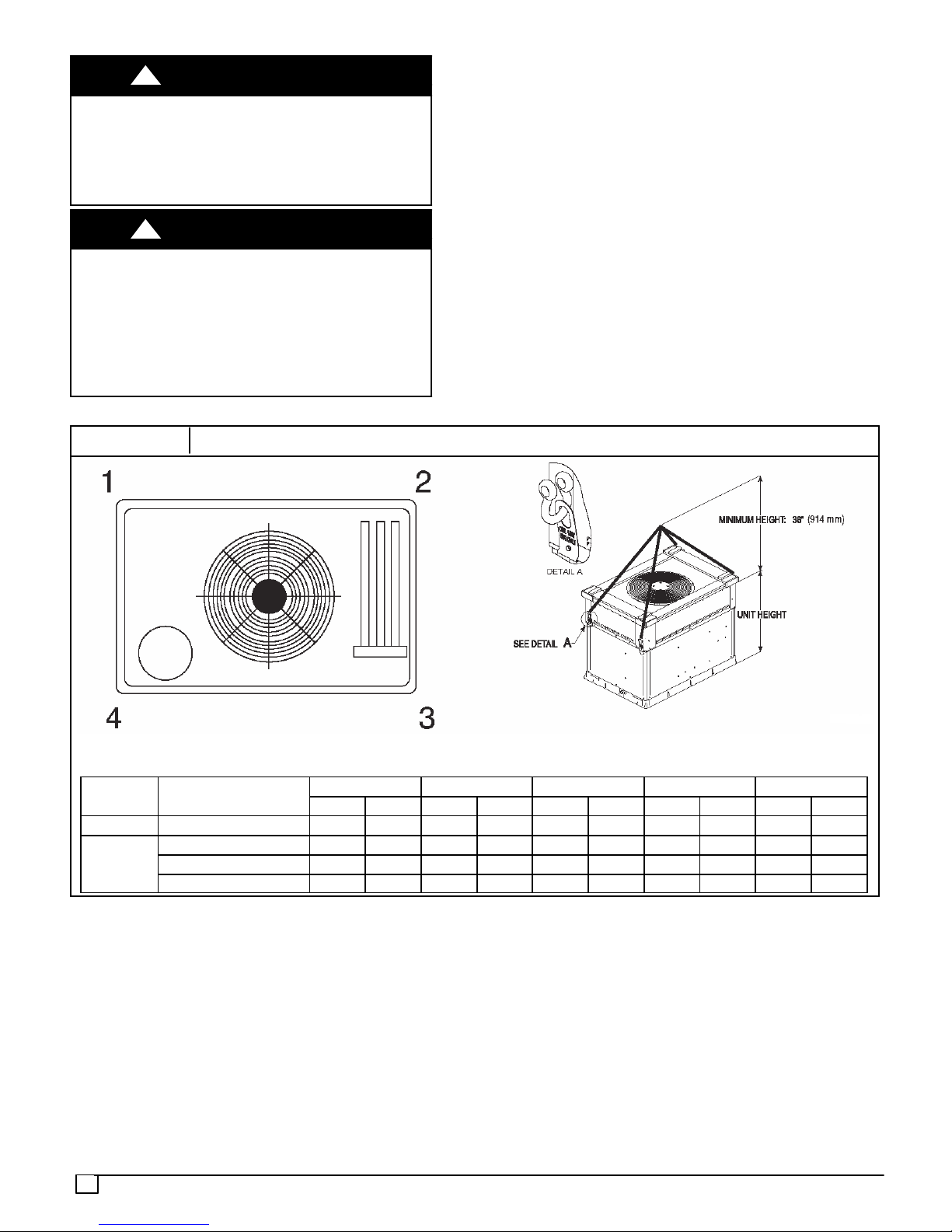
USE OF RIGGING BRACKET
NOTE: Units may require accessory kit NPLIFTBK003A10.
Field Installation of Rigging Bracket (if not already installed)
1. Remove unit from shipping carton. Leave top shipping
skid on the unit for use as a spreader bar to prevent the
rigging straps from damaging the unit. If the skid is not
available, use a spreader bar of sufficient length to
protect the unit from damage.
2. Remove 4 screws in unit corner posts.
3. Attach each of the 4 metal rigging brackets under the
panel rain lip (See Fig. 2). Use the screws removed in
step 2 above to secure the brackets to the unit.
WARNING
WARNING
WARNING
3
!
PROPERTY DAMAGE HAZARD
Failure to follow this warning could result in personal
injury/death or property damage.
Rigging bracket MUST be under the rain lip to provide
adequate lifting.
!
PROPERTY DAMAGE HAZARD
Failure to follow this warning could result in personal
injury/death or property damage.
Do not strip screws when re--securing the unit. If a screw
is stripped, replace the stripped one with a larger diameter
screw (included). When straps are taut, the clevis should
be a minimum of 36 (914mm) inches above the unit top
cover .
WARNING
WARNING
Rigging/Lifting of Unit
1. Bend top of brackets down approximately 30 degrees
from the corner posts.
2. Attach straps of equal length to the rigging brackets at
opposite ends of the unit. Be sure straps are rated to
hold the weight of the unit (See Fig. 2).
3. Attach a clevis of sufficient strength in the middle of the
straps. Adjust the clevis location to ensure unit is lifted
level with the ground.
4. After unit is securely in place detach rigging straps.
Remove corner posts screws, and rigging brackets
then reinstall screws.
After the unit is placed on the roof curb or mounting pad,
remove the top crating.
FIGURE 2
Cabinet MODEL NUMBER
Small PHN524 382 173 75 34 57 26 91 41 158 72
PHN536 469 213 93 42 71 32 113 51 192 87
Large
PHN548 497 225 104 47 63 29 136 62 193 88
PHN560 548 249 117 53 75 34 149 68 207 94
Unit Corner Weight (lbs) and Rigging
Rigging Weight 1 2 3 4
lb kg lb kg lb kg lb kg lb kg
4
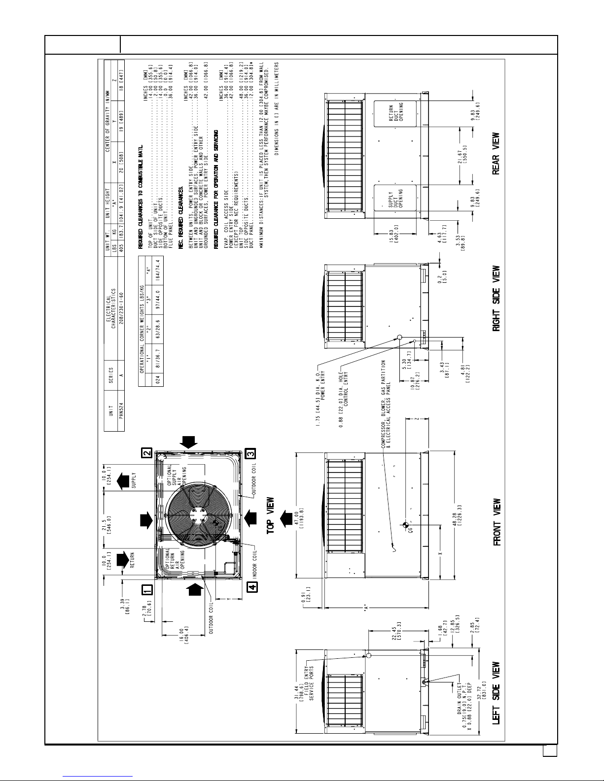
FIGURE 3
PHN524 DIMENSIONS
5
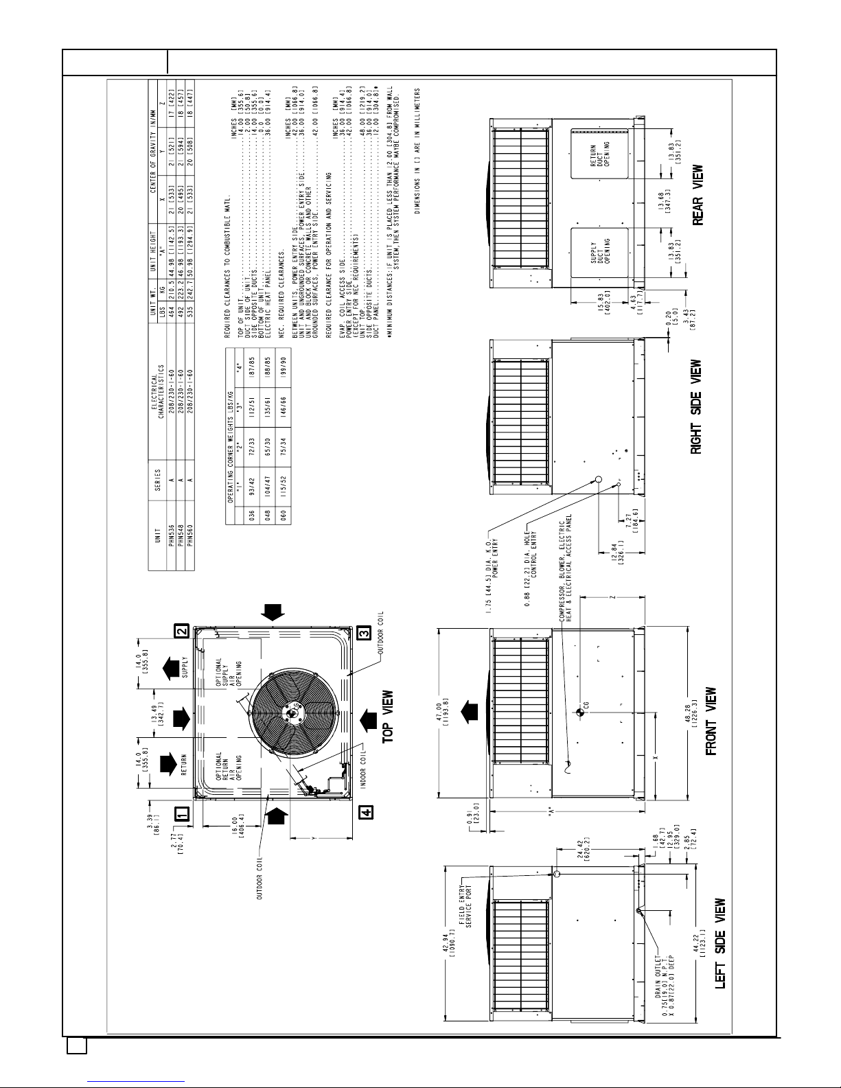
FIGURE 4
PHN536--60 DIMENSIONS
6
Step 5—Select and Install Duct Connections
The design and installation of the duct system must be in
accordance with the standards of the NFPA for installation
of non--residence type air conditioning and ventilating
systems, NFPA 90A or residence type, NFPA 90B and/or
local codes and ordinances.
Select and size ductwork, supply--air registers, and return
air grilles according to ASHRAE (American Society of
Heating, Refrigeration, and Air Conditioning Engineers)
recommendations.
The unit has duct flanges on the supply-- and return--air
openings on the side of the unit.
!
PROPERTY DAMAGE HAZARD
Failure to follow this warning could result in personal
injury/death or property damage.
For vertical supply and return units, tools or parts could
drop into ductwork. Install a 90 degree turn in the return
ductwork between the unit and the conditioned space. If
a 90 degree elbow cannot be installed, then a grille of
sufficient strength and density should be installed to
prevent objects from falling into the conditioned space.
Units with electric heaters require 90 degree elbow in
supply duct.
WARNING
When designing and installing ductwork, consider the
following:
1. All units should have field--supplied filters or accessory
filter rack installed in the return--air side of the unit.
Recommended sizes for filters are shown in Table 1.
2. Avoid abrupt duct size increases and reductions.
Abrupt change in duct size adversely affects air
performance.
IMPORT ANT: Use flexible transitions between ductwork
and unit to prevent transmission of vibration. Use suitable
gaskets to ensure weather tight and airtight seal. When
electric heat is installed, use fireproof canvas (or similar
heat resistant material) connector between ductwork and
unit discharge connection. If flexible duct is used, insert a
sheet metal sleeve inside duct. Heat resistant duct
connector (or sheet metal sleeve) must extend 24--in.
(610mm) from electric heater element.
3. Size ductwork for cooling air quantity (cfm). The
minimum air quantity for proper electric heater
operation is listed in Table 2. Heater limit switches may
trip at air quantities below those recommended.
4. Seal, insulate, and weatherproof all external ductwork.
Seal, insulate and cover with a vapor barrier all
ductwork passing through conditioned spaces. Follow
latest Sheet Metal and Air Conditioning Contractors
National Association (SMACNA) and Air Conditioning
Contractors Association (ACCA) minimum installation
standards for residential heating and air conditioning
systems.
5. Secure all ducts to building structure. Flash,
weatherproof, and vibration--isolate duct openings in
wall or roof according to good construction practices.
7
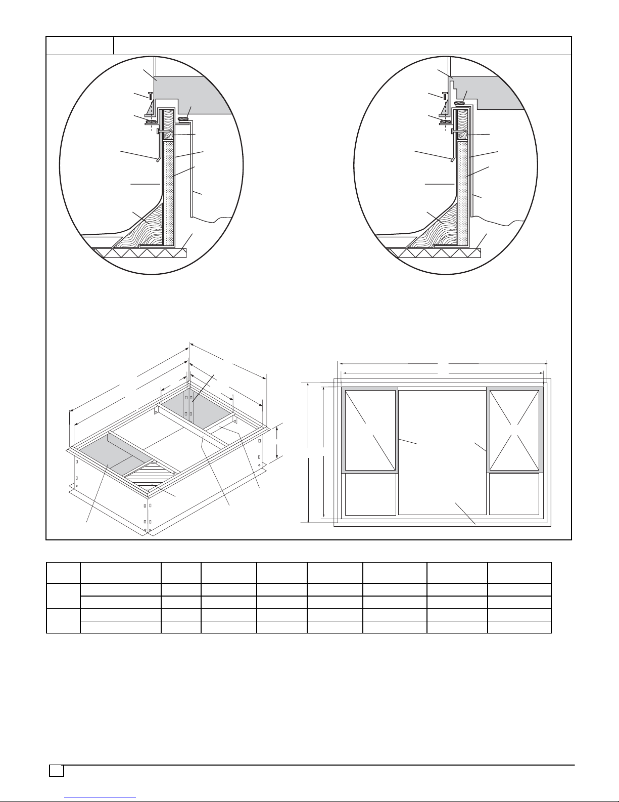
FIGURE 5
Roof Curb Dimensiona
HVAC unit
base
Scre w
(NO TE A)
*Gask eting
outer flange
Flashing field
supplied
Roofing material
field supplied
Cant str ip
field supplied
*Provided with roofcurb
Gask eting
inner flange*
Wood nailer*
Roofcurb*
Insulation (field
supplied)
Duct wo rk
field supplied
Roof
Roof Curb for Small Cabinet
Note A: When unit mounting scre w is used,
retainer bra cke t must also be used.
HVAC unit
Scre w
(NOTE A)
*Gask eting
outer flange
Flashing field
supplied
Roofing material
field supplied
Cant str ip
field supplied
*Provided with roofcurb
base
Gask eting
inner flange*
Duct wo rk
field supplied
Wood nailer*
Roofcurb*
Insulation (field
supplied)
Roof
Roof Curb for Large Cabinet
Note A: When unit mounting scre w is used,
retainer bra cket must also be used.
Model
PHN5
24
36--60
E
Supply opening
G
F
F
B Typ.
C Typ .
(B x C)
D
R/A
A
Short
Long
Support
Support
C
IN. [MM]
Return opening
(B X C)
MODEL NUMBER
Insulated
deck pan
A
IN. [MM]BIN. [MM]
NPRFCURB006A00 8 [203] 11 [279] 16--1/2 [419] 28--3/4 [730] 30--3/8 [771] 44--5/16 [1126] 45 --15/16 [1167]
NPRFCURB007A00 14 [356] 11 [279] 16--1/2 [419] 28-- 3/4 [730] 30-- 3/8 [771] 44-- 5/16 [1126] 45-- 15/16 [1167]
NPRFCURB008A00 8 [203] 16--3/16 [411] 17--3/8 [441] 40--1/4 [1022] 41--15/16 [1065] 44--7/16 [1129] 46--1/16 [1169]
NPRFCURB009A00 14 [356] 16-- 3/16 [411] 17--3/8 [441] 40-- 1/4 [1022] 41--15/16 [1065] 44--7/16 [1129] 46--1/16 [1169]
E
D
D
IN. [MM]
Insulated
deck pan
IN. [MM]
Gask et around
E
G
F
Gask et around
duct
outer edge
IN. [MM]
S/A
F
G
IN. [MM]
Notes:
1. Roof curb must be set up for unit being installed.
2. Seal strip must be applied as required to unit being installed.
3. Roof curb is made of 16 gauge steel.
4. Attach ductwork to curb (flanges of duct rest on curb).
5. Insulated panels: 1 --- in. (25.4mm) thick fiberglass 1 lb. density.
6. When unit mounting screw is used (see Note A), a retainer bracket must be used as well. This bracket must also be used when required by
code for hurricane or seismic conditions. This bracket is available through Micrometl.
8
 Loading...