

INSTALLATION INSTRUCTIONS
CONCENTRIC VENT TERMINATION KITS
NAHA001CV and NAHA002CV
NOTE: These instructions cover the installation of the concentric
vent termination kits, NAHA001CV & NAHA002CV that are
approved for use on International Comfort Products, Category IV,
90% AFUE ratings and above gas furnaces.
Safety Considerations
Improper installation, adjustment, alteration, service, maintenance,
or use can cause explosion, fire, electrical shock, or other
conditions which may cause death, personal injury, or property
damage. Consult a qualified installer, service agency, or your
distributor or branch for information or assistance. The qualified
installer or agency must use factory−authorized kits or
accessories when modifying this product. Refer to the individual
instructions packaged with the kits or accessories when installing.
Follow all safety codes. Wear safety glasses, protective clothing,
and work gloves. Use quenching cloth for brazing operations.
Have fire extinguisher available. Read these instructions
thoroughly and follow all warnings or cautions included in literature
and attached to the unit. Consult local building codes, the current
editions of the National Fuel Gas Code (NFCG) NFPA 54/ANSI
Z223.1, National Electrical Code (NEC) NFPA 70.
In Canada refer to the current editions of the National standards of
Canada CAN/CSA−B149.1 and .2 Natural Gas and Propane
Installation Codes, and Canadian Electrical Code CSA C22.1.
Recognize safety information. This is the safety−alert symbol
When you see this symbol on the unit and in instructions or
manuals, be alert to the potential for personal injury. Understand
these signal words; DANGER, WARNING, and CAUTION. These
words are used with the safety−alert symbol. DANGER identifies
the most serious hazards which will result in severe personal
injury or death. WARNING signifies hazards which could result in
personal injury or death. CAUTION is used to identify unsafe
practices which may result in minor personal injury or product and
property damage. NOTE is used to highlight suggestions which
will result in enhanced installation, reliability, or operation.
Special Venting Requirements for Installations in Canada
Installation in Canada must conform to the requirements of CSA
B149 code. Vent systems must be composed of pipe, fittings,
cements, and primers listed to ULC S636. The special vent fittings
and accessory concentric vent termination kits and accessory
external drain trap have been certified to ULC S636 for use with
those Royal Pipe and IPEX PVC vent components which have been
certified to this standard. In Canada, the primer and cement must be
of the same manufacturer as the vent system – GVS-65 Primer
(Purple) for Royal Pipe or IPEX System 636, PVC/CPVC Primer,
Purple Violet for Flue Gas Venting and GVS-65 PVC Solvent Cement
for Royal Pipe or IPEX System 636
Venting, rated Class IIA, 65 deg C. must be used with this venting
system - do not mix primers and cements from one manufacturer with
a vent system from a different manufacturer. Follow the
manufacturer’s instructions in the use of primer and cement and
never use primer or cement beyond its expiration date.
The safe operation, as defined by ULC S636, of the vent system is
based on following these installation instructions, the vent system
manufacturer’s installation instructions, and proper use of primer
and cement. All fire stop and roof flashing used with this system must
be UL listed material. Acceptability under Canadian standard CSA
B149 is dependent upon full compliance with all installation
instructions. Under this standard, it is recommended that the vent
system be checked once a year by qualified service personnel.
t, PVC Cement for Flue Gas
(1)
The authority having jurisdiction (gas inspection authority, municipal
building department, fire department, etc) should be consulted
before installation to determine the need to obtain a permit.
(1) System 636 is a trademark of IPEX Inc.
Consignes spéciales pour l’installation de ventillation au
Canada
L’installation faite au Canada doit se conformer aux exigences du
code CSA B149. Ce systême de ventillation doit se composer de
tuyaux, raccords, ciments et apprêts conformes au ULC S636. La
tuyauterie de ventillation des gaz, ses accessoires, le terminal
concentrique mural ainsi que l’ensemble du drain de condensat
extérieur ont été certifiés ULCS 636 pour l’application des
composantes Royal Pipe, IPEX PVC qui sont certifiées à ce
standard. Au Canada, l’apprêt et le ciment doivent être du même
fabricant que le système d’évacuation. L’apprêt GVS-65 (Purple) et
le ciment-solvant GVS-65 doivent être utilisé avec les Royal Pipe.
Système IPEX 636, apprêt PVC/CPVC, Purple pour évacuation des
gaz de combustion et système IPEX 636(1)t, ciment PVC pour
évacuation des gaz de combustion, coté classe IIA, 65 deg C.
doivent être utilisés avec le système d’évacuation IPEX 636 – Ne pas
combiner l’apprêt et le ciment d’un manufacturier avec un système
d’évacuation d’un manufacturier différent.
Bien suivre les indications du manufacturier lors de l’utilisation de
.
l’apprêt et du ciment et ne pas utiliser ceux-ci si la date d’expiration
est atteinte.
L’opération sécuritaire, tel que définit par ULC S636, du système de
ventilation est basé sur les instructions d’installation suivantes, ainsi
que l’usage approprié de l’apprêt et ciment. Tout arrët feu et solin de
toit utilisés avec ce système doivent être des matériaux listés UL.
L’acceptation du standard Canadien CSA B419 est directement relié
à l’installation conforme aux instructions ci- haut mentionnées. Le
standard Canadien recommande l’inspection par un personel
qualifié et ce, une fois par année.
Les autoritées ayant juridiction (inspecteurs de gas, inspecteurs en
bâtiments, département des incendies, etc) devraient être
consultées avant l’installation afin de déterminer si un permis est
requis.
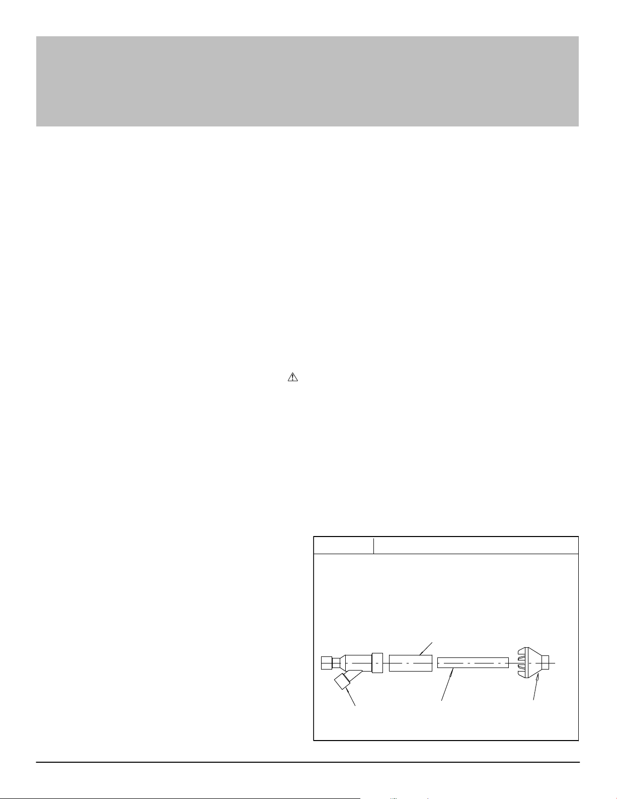
Figure 1
Kit Contents:
3″ (76.2mm) Rain Cap or 2″ (50.8mm) Rain Cap
3″ (76.2mm) Diameter SDR−26 Pipe, 19
4″ (101.6mm) Diameter SDR−26 Pipe, 24″ (609.6mm) Long,
2″ (50.8mm) Diameter SDR−26 Pipe, 31
1
2
/2″ (63.5mm) Diameter SDR−26 Pipe, 371/8″ (943mm) Long,
3″ (76.2mm) Y Concentric Fitting or 2″ (50.8mm) Y Concentric Fitting
2″ (50.8mm) or 3″
(76.2mm) Dia.
Y Concentric Fitting
Kit Components
3″ (76.2mm) or 4″ (101.6mm) Dia.
SDR−26 Pipe
2 (50.8mm) or
1
2
/2″ (63.5mm)
Dia. SDR−26 Pipe
1
/2″ (495.3mm) Long or
5
/8″ (803.3mm) Long or
2″ (50.8mm) or 3″
(76.2mm) Dia.
Rain Cap
25-22-03
Specifications subject to change without notice.
441 06 1018 03 Dec. 2010
CONCENTRIC VENT KIT
These kits are for vertical or horizontal termination of the combustion
air inlet and the exhaust vent pipes on Category IV gas−fired
condensing furnaces. The NAHA001CV kit can be used for 3″
(76.2mm) diameter pipe systems. The NAHA002CV kit can be used
for 2″ (50.8mm) diameter pipe system. Refer to Furnace Installation
Instructions for the correct pipe size for the furnace. Both the
combustion air inlet and the exhaust vent pipes must attach to the
termination kit. The termination kit must terminate outside the
structure and must be installed per the instructions outlined below for
vertical or horizontal termination. Vertical termination is preferred.
Field supplied pipe and fittings are required to complete the
installation.
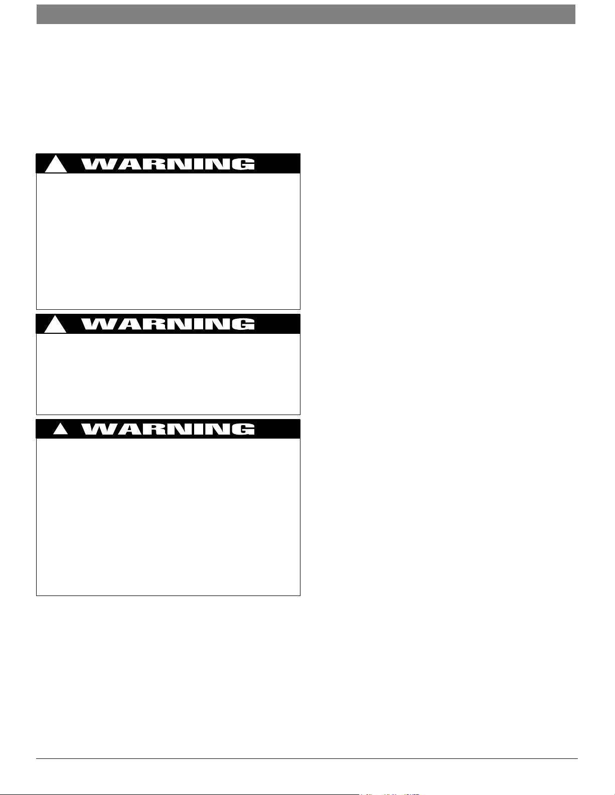
!
ELECTRIC SHOCK HAZARD/FIRE AND/OR
EXPLOSION HAZARD
Failure to follow this warning could result in personal
injury, death, property damage and/or equipment
damage.
Turn OFF gas supply at manual gas valve before
turning OFF electric power supply and starting
installation.
Turn OFF electric power supply at disconnect switch
or service panel before starting installation. Tag and
lockout shutoff(s) with appropriate device warning labels. There may be more than one disconnect.
!
CARBON MONOXIDE POISONING, AND PROPERTY
DAMAGE HAZARD
Failure to follow this warning could result in
personal injury, death, property damage.
This kit is to be used for terminating condensing
Category IV vent furnaces. DO NOT use kit to
terminate Category I, II, or III vent furnaces.
!
ELECTRIC SHOCK HAZARD/FIRE AND/OR EXPLOSION HAZARD
Failure to carefully read and follow all instructions in
these instructions could result in personal injury,
death, property damage and/or furnace malfunction.
Installation or repairs made by unqualified persons
could result in hazards to you and others.
Installation MUST conform with local codes or, in the
absence of local codes, with codes of the country
having jurisdiction.
The information contained in these instructions is
intended for use by a qualified service technician
familiar with safety procedures and equipped with
the proper tools and test instruments.
Follow the furnace installation instructions for locating the furnace,
clearances, operation and safety procedures. Use these instructions
for installation of the concentric vent termination kit.
Read these instructions completely before attempting installation.
Field supplied pipe and fittings are required to complete installation.
NOTE: All pipe, fittings, solvent cement, primers and procedures
WARNING
MUST conform to American National Standards Institute (ANSI) and
American Society for Testing and Materials (ASTM) Standards:
Pipe and Fittings: − D1785, D2466, D2661, D2665, F−891,
F628, D2665, D2241
PVC Primer & Solvent Cement − D2564 & D2235
Procedure for Cement Joints − D2855
NOTE: In order to create a seal that allows future removal of pipe,
RTV sealant MUST be used on the inlet pipe where it joins to the
furnace. PVC, CPVC, ABS and Cellular Core pipe and cement may
be used on all other joints.
In Canada, refer to Special Venting Requirements for Installations in
Canada.
Vent Termination Clearances
1. The Province of Alberta requires a minimum unobstructed
distance of 4 ft. (1.2m) from the foundation to the property line of
the adjacent lot for vent termination of any appliance with an
input over 35,000 btuh. This means, if there is less than 4 ft.
(1.2m) of unobstructed distance to the property line of the
adjacent lot, no type of vent termination is permitted for
appliances with inputs greater than 35,000 btuh.
The Province of Alberta does not interpret any restrictions on
unobstructed distances greater than 8 ft. (2.4m). This means
that all single, two-pipe and concentric vents may be used,
providing all other Code and manufacturer’s requirements are
adhered to.
The requirement is to re-direct the flue gas plume when the
unobstructed distance from the foundation to the property line of
the adjacent lot is no less than 4 ft. (1.2m) and no greater than 8
ft. (2.4m).
In venting situations where the unobstructed distance from the
foundation to the property line of the adjacent lot is between 4 ft.
(1.2m) and 8 ft. (2.4m), the concentric vent kit cannot be used.
The concentric vent kit cannot be modified to attach a tee or
elbow to the vent portion of the rain cap. A tee or elbow attached
to the rain cap could potentially direct the flue gas plume toward
the intake air stream and contaminate the incoming combustion
air for the furnace.
In a venting situation where the unobstructed distance from the
foundation to the property line of the adjacent lot is between 4 ft.
(1.2m) and 8 ft. (2.4m), a 2-pipe termination (or single pipe when
permitted) must be used.
2. With the exception of The Province of Alberta, Canada,
determine termination locations based on clearances specified
in furnace installation instruction, and following steps as shown
in Figure 2, Figure 5 through Figure 8.
3. The vent termination must be located at least 12″ (304.8mm)
above ground or normally expected snow accumulation levels.
4. Do NOT terminate over public walkways. Avoid areas where
condensate may cause problems such as above planters,
patios, or adjacent to windows where steam may cause fogging.
5. The vent termination shall be located at least 3′ (.9m)
horizontally from any electric meter, gas meter, regulator, and
any relief equipment.
6. The vent termination is to be located at least 3′ (.9m) above any
forced air inlet located within 10′ (3m); and at least 10′ (3m) from
a combustion air intake of another appliance, except another
direct vent furnace intake.
7. In Canada, refer to Special Venting Requirements for
Installations in Canada and the Province of Alberta
requirements and the National Standards of Canada, Natural
Gas, Propane Installation Codes (NSCNGPIC).
2
Specifications subject to change without notice.
441 06 1018 03

CONCENTRIC VENT KIT
Vertical & Horizontal Termination
1. Determine the pipe diameters required for the installation from
Furnace Installation Instructions.
2. Determine the best location for the termination kit. See Figure 2
for vertical termination or Figure 5 for horizontal termination.
Roof termination is preferred since it is less susceptible to
damage, has reduced intake contaminants and less visible vent
vapor. For side wall termination, consideration should be given
to: 1) possible damage from the vapors to plants/shrubs, other
equipment and building materials, 2) possible damage to the
terminal from foreign objects, 3) wind effects that may cause
recirculation of flue products, debris or light snow and 4) visible
vent vapor.
3. Cut one 5″ (127mm) diameter hole through the structure for the
NAHA001CV Kit or one 4″ (101.6mm) diameter hole for the
NAHA002CV Kit .
4. Dimension D may be lengthened to 60″〈1524mm)max. or
shortened by cutting the pipes to 12″(304.8mm) min. Dimension
A will change according to D dimension. (See Figure 3)
Figure 2
Roof Boot/
Flashing
(Field Supplied)
Concentric Vent Roof Installation
Vent
Combustion
Air
Maintain 12″ (304.8mm)
min. clearance above
highest anticipated snow
level. Max. of 24″
(609.6mm) above roof.
Support
(Field Supplied)
Figure 3
1
/2″
1
(38.1mm)
Model A* B C D**
NAHA001CV 387/8(987.4) 3(76.2) 41/2(114.3) 211/8(536.6)
NAHA002CV 333/8(847.7) 2(50.8) 31/2(88.9) 165/8(422.3)
* = Dimension will change accordingly as dimension D is
lengthened or shortened.
** = Dimension D may be lengthened to 60″ (1524mm) may also be
shortened by cutting the pipes provided in the kit to 12″ (304.8mm)
minimum
Concentric Vent Dimensional
Drawing in(mm)
B PVC
Vent/Exhaust
C
B
PVC Intake/Combustion Air
D
A
25−22−03
5. Partially assemble the concentric vent termination kit. Clean and
cement the parts using the procedures for Joining Pipe and
Fittings section of the furnace installation manual. A) Cement
the Y Concentric fitting to the larger diameter kit pipe. (See
Figure 1) B) Cement the rain cap to the smaller diameter kit
part. (See Figure 1) NOTE: A field supplied stainless steel
screw may be used to secure the rain cap to the pipe instead of
cementing when field disassembly is desired for cleaning (See
Figure 4)
45° Elbow
(Field Supplied)
Vent
Combustion
Air
Note:
Support must be field installed to secure termination kit to structure.
25-22-02
!
UNIT OPERATION HAZARD
Failure to follow this caution may result in
intermittent unit operation.
Do not use field supplied couplings to extend the
pipes. Airflow restriction will occur and the furnace
pressure switch may cause intermittent operation.
If assembly needs to be extended to meet height or side wall
thickness requirement, the two pipes supplied in the kit may be
replaced by using the same diameter solid, single (no coupling
connections) field supplied SDR−26 PVC (ASTM D2241) pipes. Do
not extend dimension D more than 60″(1524mm). (See Figure 3)
Figure 4
25-22-02
!
Rain Cap to Vent Pipe Assembly
Drill clearance hole in rain
cap and pilot hole in vent pipe.
Stainless steel screw
(Field supplied)
WARNING
CARBON MONOXIDE POISONING, FIRE AND
EXPLOSION HAZARD
Failure to follow this warning could result in
personal injury, death, and/or property damage.
When using the alternate screw assembly method,
drill a clearance hole in the rain cap and a pilot hole
in the vent pipe for the screw size being used.
Failure to drill adequate holes may cause cracking
of the PVC components, allowing flue gases to be
recirculated.
441 06 1018 03
Specifications subject to change without notice.
3

CONCENTRIC VENT KIT
!
WARNING
CARBON MONOXIDE POISONING, FIRE AND
EXPLOSION HAZARD.
Failure to follow this warning could result in
personal injury, death, and/or property damage.
Do not operate the furnace with the rain cap
removed as recirculation of the flue gases may
occur. Water may also collect inside the larger
combustion air pipe and flow to the burner
enclosure.
6. Install the Y concentric fitting and the pipe assembly through the
structure’s hole. For vertical termination, install the parts
through the field supplied roof boot/flashing. NOTE: Do not
allow insulation or other materials to accumulate inside the pipe
assembly when installing through the structure’s hole.
7. Secure the assembly to the structure as shown in Figure 2 or
Figure 6 using field supplied metal strapping or equivalent
material.
NOTE: Ensure the termination height is above the roof surface
or anticipated snow level as shown in Figure 2 for vertical
termination. Ensure the termination location clearance
dimensions are as shown in Figure 5 and Figure 6 for
horizontal termination.
Figure 5
Concentric Vent and Combustion−
Air Side Termination
Roof Overhang
8. Install the rain cap and the small diameter pipe assembly in the Y
concentric fitting and the large pipe assembly. Ensure that the
small diameter pipe is bottomed out and securely cemented in
the Y concentric fitting.
9. Cement the furnace combustion air and vent pipes to the
concentric vent termination assembly. See Figure 2 or Figure 6
for proper pipe attachment.
10.Operate the furnace through one heat cycle to ensure
combustion air and vent pipes are properly connected to the
concentric termination connections.
Multi Vent Termination Clearances
When two (2) or more furnaces are vented near each other, each
furnace must be individually vented.
Two (2) vent terminations may be installed as shown in Figure 7 and
Figure 8, but the next vent termination or pair of vent terminations,
must be at least 36″ (914.4mm) away from first two (2) terminations.
It is important that vent terminations guidelines are followed to avoid
recirculation of flue gases.
Figure 7
12, Min.
(304.8mm)
Grade or
Snow Level
Combustion
Air
Concentric Vent and Combustion−
Air Roof Termination
2” max.
(50.8mm)
36” min.
(914.4mm)
Exhaust
OR
36” min.
(914.4mm)
12″ min.
1″ max.
(25.4mm)
25-22-02
Figure 6
Vent
Combustion
Air
Note:
Securing strap must be field installed to prevent movement of
termination kit in side wall.
Concentric Vent Sidewall Attachment
(304.8mm)
Combustion
Air
Vent
Maintain 12″ (304.8mm) clearance
above highest anticipated snow
level or grade whichever is greater.
Strap
(Field Supplied)
45° Elbow
(Field Supplied)
Combustion
Air
Flush to
1″ max.
(25.4mm)
Vent
25-22-02
Figure 8
Combustion Air
Dimension “A” is touching or 2″ (50.8) maximum separation.
Concentric Vent and Combustion−
Air Sidewall Termination
1, Maximum (TYP.)
(25.4mm)
Vent
“A”
Exhaust
Vent
25-22-02d
International Comfort Product, LLC S PO Box 128 S Lewisburg, TN 37091 USA
4
Specifications subject to change without notice.
441 06 1018 03
 Loading...