

International comfort products N9MP1, N9MPD, C9MPD, H9MPD, T9MPD Installation Instructions Manual
...
INSTALLATION INSTRUCTIONS
90+ Single Stage, Category IV, Gas Furnace
N9MP1, N9MP2, N9MPD
(Upflow/Downflow/Horizontal)
C9MPD, H9MPD, T9MPD
These instructions must be read and understood completely before attempting installation.
Safety Labeling and Signal Words
DANGER, WARNING, CAUTION, and NOTE
The signal words DANGER, WARNING,
CAUTION, and NOTE are used to identify levels of
hazard seriousness. The signal word DANGER is
only used on product labels to signify an immediate
hazard. The signal words WARNING, CAUTION,
and NOTE will be used on product labels and
throughout this manual and other manual that may
apply to the product.
DANGER − Immediate hazards which will result in
severe personal injury or death.
WARNING − Hazards or unsafe practices which
could result in severe personal injury or death.
CAUTION − Hazards or unsafe practices which
may result in minor personal injury or product or
property damage.
NOTE − Used to highlight suggestions which will
result in enhanced installation, reliability, or
operation.
Signal Words in Manuals
The signal word WARNING is used throughout
this manual in the following manner:
!
WARNING
The signal word CAUTION is used throughout
this manual in the following manner:
!
CAUTION
Signal Words on Product Labeling
Signal words are used in combination with
colors and/or pictures or product labels.
Safety−alert symbol
When you see this symbol on the unit and in
instructions or manuals, be alert to the
potential for personal injury.
TABLE OF CONTENTS
Safety considerations 4...........................
Safe Installation Requirements 4...................
Installation 6.....................................
Combustion & Ventilation Air 10.....................
Vent and Combustion Air Piping 14..................
Concentric Termination 32..........................
Gas Supply and Piping 33..........................
Electrical Wiring 38................................
Ductwork and Filter 39.............................
Checks and Adjustments 42........................
Furnace Maintenance 45...........................
Sequence of Operation & Diagnostics 46.............
Technical Support 48..............................
Use of the AHRI Certified TM Mark indicates a
manufacturer’s participation in the program.
For verification of certification for individual
products, go to www.ahridirectory.org .
International Comfort Products, LLC
Lewisburg, TN 37091 U.S.A.
www.icpusa.com
Portions of the text and tables are reprinted from NFPA 54 /ANSI Z223.1−2009©, with permission of National Fire Protection Association, Quincy, MA 02269 and American Gas Association, Washington, DC
20001. This reprinted material is not the complete and official position of the NFPA or ANSI, on the referenced subject, which is represented only by the standard in its entirety.
PERSONAL INJURY, AND/OR PROPERTY
DAMAGE HAZARD
Failure to carefully read and follow this warning could
result in equipment malfunction, property damage,
personal injury and/or death.
Installation or repairs made by unqualified persons could
result in equipment malfunction, property damage,
personal injury and/or death.
The information contained in this manual is intended for
use by a qualified service technician familiar with safety
procedures and equipped with proper tools and test
instruments.
Installation must conform with local building codes and
with the Natural Fuel Gas Code (NFCG) NFPA 54/ANSI
Z223.1, and National standards of Canada
CAN/CSA−B149.1 and .2 Natural Gas and Propane
Installation Codes.
INSTALLER: Affix these instructions on or adjacent to the
furnace.
CONSUMER: Retain these instructions for future
reference.
!
WARNING
Printed in U.S.A. 440 01 1024 04 Dec. 2010

Required Notice for Massachusetts Installations
Important
The Commonwealth of Massachusetts requires compliance with regulation 248 CMR as follows:
5.08: Modifications to NFPA−54, Chapter 10
2) Revise 10.8.3 by adding the following additional requirements:
(a) For all side wall horizontally vented gas fueled equipment installed in every dwelling, building or structure used in whole or in part for residential
purposes, including those owned or operated by the Commonwealth and where the side wall exhaust vent termination is less than seven (7) feet
above finished grade in the area of the venting, including but not limited to decks and porches, the following requirements shall be satisfied:
1. INSTALLATION OF CARBON MONOXIDE DETECTORS. At the time of installation of the side wall horizontal vented gas fueled equipment, the
installing plumber or gasfitter shall observe that a hard wired carbon monoxide detector with an alarm and battery back−up is installed on the floor
level where the gas equipment is to be installed. in addition, the installing plumber or gasfitter shall observe that a battery operated or hard wired
carbon monoxide detector with an alarm is installed on each additional level of the dwelling, building or structure served by the side wall
horizontal vented gas fueled equipment. It shall be the responsibility of the property owner to secure the services of qualified license
professionals for the installation of hard wired carbon monoxide detectors.
a. In the event that the side wall horizontally vented gas fueled equipment is installed in a crawl space or an attic, the hard wired carbon
monoxide detector with alarm and battery back−up may be installed on the next adjacent floor level.
b. In the event that the requirements of this subdivision can not be met at the time of completion of installation, the owner shall have a period of
thirty (30) days to comply with the above requirement; provided, however, that during said thirty (30) day period, a battery operated carbon
monoxide detector with an alarm shall be installed.
2. APPROVED CARBON MONOXIDE DETECTORS. Each carbon monoxide detector as required in accordance with the above provisions shall
comply with NFPA 720 and be ANSI/UL 2034 listed and IAS certified.
3. SIGNAGE. A metal or plastic identification plate shall be permanently mounted to the exterior of the building at a minimum height of eight (8) feet
above grade directly in line with the exhaust vent terminal for the horizontally vented gas fueled heating appliance or equipment. The sign shall
read, in print size no less than one−half (1/2) inch in size, “GAS VENT DIRECTLY BELOW. KEEP CLEAR OF ALL OBSTRUCTIONS”.
4. INSPECTION. The state of local gas inspector of the side wall horizontally vented gas fueled equipment shall not approve the installation unless,
upon inspection, the inspector observes carbon monoxide detectors and signage installed in accordance with the provisions of 248 CMR
5.08(2)(a) 1 through 4.
(b) EXEMPTIONS: The following equipment is exempt from 248 CMR 5.08(2)(a) 1 through 4:
1. The equipment listed in Chapter 10 entitled “Equipment Not Required To Be Vented” in the most current edition of NFPA 54 as adopted by the
Board; and
2. Product Approved side wall horizontally vented gas fueled equipment installed in a room or structure separate from the dwelling, building or
structure used in whole or in part for residential purposes.
(c) MANUFACTURER REQUIREMENTS − GAS EQUIPMENT VENTING SYSTEM PROVIDED. When the manufacturer of Product Approved side wall
horizontally vented gas equipment provides a venting system design or venting system components with the equipment, the instructions provided by
the manufacturer for installation of the equipment and the venting system shall include:
1. Detailed instructions for the installation of the venting system design or the venting system components; and
2. A complete parts list for the venting system design or venting system.
(d) MANUFACTURER REQUIREMENTS − GAS EQUIPMENT VENTING SYSTEM NOT PROVIDED. When the manufacturer of a Product Approved side
wall horizontally vented gas fueled equipment does not provide the parts for venting the flue gases, but identifies “special venting systems”, the
following requirements shall be satisfied by the manufacturer:
1. The referenced “special venting system” instructions shall be included with the appliance or equipment installation instructions; and
2. The “special venting systems” shall be Product Approved by the Board, and the instructions for that system shall include a parts list and detailed
installation instructions.
(e) A copy of all installation instructions for all Product Approved side wall horizontally vented gas fueled equipment, all venting instructions, all parts lists
for venting instructions, and/or all venting design instructions shall remain with the appliance or equipment at the completion of the installation.
For questions regarding these requirements, please contact the Commonwealth of Massachusetts Board of State Examiners of Plumbers and Gas
Fitters, 239 Causeway Street, Boston, MA 02114. 617−727−9952
440 01 1024 04
Specifications are subject to change without notice.
2

START−UP CHECK SHEET
For 90+ Furnace
(This sheet is optional. Keep this page for future reference.)
Date of Start−Up:
Dealer Name:
Address:
City, State(Province), Zip or Postal Code:
Phone:
Owner Name:
Address:
City, State(Province), Zip or Postal Code:
Model Number:
Serial Number:
Setup Checks
Check the box when task is complete
Calculated Firing Rate:(See Checks and Adjustments
Section).
Heating Check
Measured Line Pressure when Firing Unit:
Measured Manifold Gas Pressure:
Temperature of Supply Air: (°)
Temperature of Return Air: (°)
Temperature Rise (supply−return temperature): (°)
In Rise (see furnace rating plate)? (°)
Static Pressure (Ducts): Supply Air Return
Which blower speed tap is used? (Heating)
Optional Check: CO ? CO2 ?
Cooling Check
Temperature of Supply Air: (°)
All Electrical Connections Tight?
Have hoses been relocated for furnace application
(upflow/horizontal)?
Condensate Drain Connected?
Condensate Drain Trapped?
Manual Gas Shut−Off Upstream of Furnace/Drip−Leg?
Gas Valve turned ON?
Type of Gas: Natural: Propane:
Filter Type and Size:
Temperature of Return Air: (°)
Temperature Difference: (°)
Static Pressure (Ducts) cooling: Supply Air Return
Blower Speed Tap used for cooling: _______
Dealer Comments:
3
Specifications are subject to change without notice.
440 01 1024 04
SAFETY CONSIDERATIONS
Improper installation, adjustment, alteration, service,
maintenance, or use can cause explosion, fire, electrical shock,
or other conditions which may cause death, personal injury, or
property damage. Consult a qualified installer, service agency,
or your distributor or branch for information or assistance. The
qualified installer or agency must use factory−authorized kits or
accessories when modifying this product. Refer to the individual
instructions packaged with the kits or accessories when
installing.
Follow all safety codes. Wear safety glasses, protective
clothing, and work gloves. Use quenching cloth for
brazing operations. Have fire extinguisher available.
Read these instructions thoroughly and follow all
warnings or cautions included in literature and attached
to the unit. Consult local building codes, the current
editions of the National Fuel Gas Code (NFCG) NFPA
54/ANSI Z223.1, and the National Electrical Code (NEC)
NFPA 70.
In Canada refer to the current editions of the National
standards of Canada CAN/CSA−B149.1 and .2 Natural
Gas and Propane Installation Codes, and Canadian
Electrical Code CSA C22.1.
Recognize safety information. This is the safety−alert
symbol . When you see this symbol on the unit and in
instructions or manuals, be alert to the potential for
personal injury. Understand these signal words;
DANGER, WARNING, and CAUTION. These words are
used with the safety−alert symbol. DANGER identifies the
most serious hazards which will result in severe personal
injury or death. WARNING signifies hazards which could
result in personal injury or death. CAUTION is used to
identify unsafe practices which may result in minor
personal injury or product and property damage. NOTE is
used to highlight suggestions which will result in
enhanced installation, reliability, or operation.
!
WARNING
ELECTRICAL SHOCK HAZARD
Failure to follow this warning could cause personal
injury or death.
Before performing service or maintenance operations
on unit, always turn off main power switch to unit and
install lockout tag. Unit may have more than one
power switch.
!
WARNING
CARBON MONOXIDE POISONING AND FIRE
HAZARD
Failure to follow safety warnings could result in
personal injury, death, and/or property damage.
This furnace is not designed for use in mobile homes,
trailers or recreational vehicles.
!
CUT HAZARD
Failure to follow this caution may result in damage
personal injury.
Sheet metal parts may have sharp edges or burrs.
Use care and wear appropriate protective clothing,
safety glasses and gloves when handling parts and
servicing furnaces.
CAUTION
Safe Installation Requirements
!
FIRE, EXPLOSION, AND ASPHYXIATION HAZARD
Improper adjustment, alteration, service,
maintenance or installation could cause personal
injury, death and/or property damage.
Installation or repairs made by unqualified persons
could result in hazards to you and others.
Installation MUST conform with local codes or, in
the absence of local codes, with codes of all
governmental authorities having jurisdiction.
The information contained in this manual is
intended for use by a qualified service agency that
is experienced in such work, is familiar with all
precautions and safety procedures required in
such work, and is equipped with the proper tools
and test instruments.
NOTE: This furnace is design−certified by the CSA International
(formerly AGA and CGA) for installation in the United States and
Canada. Refer to the appropriate codes, along with this manual,
for proper installation.
WARNING
• Use only the Type of gas approved for this furnace (see
Rating Plate on unit). Overfiring will result in failure of heat
exchanger and cause dangerous operation. (Furnaces
can be converted to Propane gas with approved kit.)
• Install this furnace only in a location and position as
specified in “Installation” of these instructions.
• Provide adequate combustion and ventilation air to the
furnace as specified in “Combustion and Ventilation Air” of
these instructions.
• Combustion products must be discharged outdoors.
Connect this furnace to an approved vent system only, as
specified in “Vent and Combustion Air Piping” of these
instructions.
• Never test for gas leaks with an open flame. Use a
commercially available soap solution made specifically for
the detection of leaks to check all connections, as
specified in “Gas Supply and Piping, Final Check” of these
instructions.
• Always install furnace to operate within the furnace’s
intended temperature−rise range with a duct system which
has an external static pressure within the allowable range,
as specified in “Technical Support Manual” of these
instructions. See furnace rating plate.
4
440 01 1024 04
Specifications are subject to change without notice
• When a furnace is installed so that supply ducts carry air
circulated by the furnace to areas outside the space
containing the furnace, the return air shall also be handled
by a duct(s) sealed to the furnace casing and terminating
outside the space containing the furnace.
• A gas−fired furnace for installation in a residential garage
must be installed as specified in “Installation” of these
instructions.
• This furnace is not to be used for temporary heating of
buildings or structures under construction.
• This furnace is NOT approved for installation in
mobile homes, trailers or recreation vehicles.
• Seal around supply and return air ducts.
• Install correct filter type and size.
• Unit MUST be installed so electrical components are
protected from direct contact with water.
Safety Rules
Your unit is built to provide many years of safe and dependable
service providing it is properly installed and maintained. However,
abuse and/or improper use can shorten the life of the unit and
create hazards for you, the owner.
A. The U.S. Consumer Product Safety Commission encourages
installation of carbon monoxide alarms. There can be various
sources of carbon monoxide in a building or dwelling. The
sources could be gas−fired clothes dryers, gas cooking
stoves, water heaters, furnaces, gas−fired fireplaces, wood
fireplaces.
Carbon monoxide can cause serious bodily injury and/or
death. Carbon monoxide or “CO” is a colorless and odorless
gas produced when fuel is not burned completely or when the
flame does not receive sufficient oxygen.
Therefore, to help alert people of potentially dangerous carbon
monoxide levels, you should have a commercially available
carbon monoxide alarm that is listed by a nationally
recognized testing agency in accordance with Underwriters
Laboratories Inc. Standard for Single and Multiple Station
Carbon Monoxide Alarms, ANSI/UL 2034 or the CSA 6.19−01
Residential Carbon Alarming Devices installed and
maintained in the building or dwelling concurrently with the
gas−fired furnace installation (see Note below). The alarm
should be installed as recommended by the alarm
manufacturer’s installation instructions.
B. There can be numerous sources of fire or smoke in a building
or dwelling. Fire or smoke can cause serious bodily injury,
death, and/or property damage. Therefore, in order to alert
people of potentially dangerous fire or smoke, you should have
fire extinguisher and smoke alarms listed by Underwriters
Laboratories installed and maintained in the building or
dwelling (see Note below).
Note: The manufacturer of your furnace does not test any alarms
and makes no representations regarding any brand or type
of alarms.
C. To ensure safe and efficient operation of your unit, you should
do the following:
1. Thoroughly read this manual and labels on the unit. This
will help you understand how your unit operates and the
hazards involved with gas and electricity.
2. Do not use this unit if any part has been under water.
Immediately call a qualified service technician to inspect the
unit and to replace any part of the control system and any gas
control which has been under water.
3. Never obstruct the vent grilles, or any ducts that provide
air to the unit. Air must be provided for proper combustion
and ventilation of flue gases.
Frozen Water Pipe Hazard
!
WATER DAMAGE TO PROPERTY HAZARD
Failure to follow this caution may result in property
damage.
Do not leave your home unattended for long periods
during freezing weather without turning off water
supply and draining water pipes or otherwise
protecting against the risk of frozen pipes and
resultant damage.
Your furnace is designed solely to provide a safe and comfortable
living environment. The furnace is NOT designed to ensure that
water pipes will not freeze. It is equipped with several safety
devices that are designed to turn the furnace off and prevent it from
restarting in the event of various potentially unsafe conditions.
If your furnace remains off for an extended time, the pipes in your
home could freeze and burst, resulting in serious water damage.
If the structure will be unattended during cold weather you should
take these precautions.
1. Turn off the water supply to the structure and drain the water
lines if possible and add an antifreeze for potable water to
drain traps and toilet tanks. Open faucets in appropriate
areas.
2. Have someone check the structure frequently during cold
weather to make sure it is warm enough to prevent pipes
from freezing. Instruct them on a service agency to call to
provide service, if required.
3. Install a reliable remote sensing device that will notify
somebody of freezing conditions within the home.
Winter Shutdown
If you go away during the winter months and do not leave the heat
on in your home, the plastic transition box and the condensate trap
on the furnace must be protected from freeze damage.(See
Figure 11 trough Figure 20)
1. Disconnect the
drain fitting that is located downstream of the combustion
blower. Insert a funnel into the hose and pour four(4) ounces
of sanitary type (RV) antifreeze into the condensate trap.
Reconnect the
the vent drain fitting. Secure with the hose clamp.
2. Disconnect the
condensate trap. Insert a funnel into the hose and and pour
four(4) ounces of sanitary type (RV) antifreeze into the
plastic Transition box. Squeeze the hose together near the
end and quickly reconnect the
hose to the stub on the condensate trap. Secure with the
hose clamp.
When you return home, your furnace will be ready to start, as it is
not necessary to drain the antifreeze from the furnace.
CAUTION
−or−
−or−
5
/8″ (15.9mm) OD rubber hose from the vent
5
/8″(15.9mm) OD rubber hose to the stub on
3
/4″ (15.9mm)OD rubber hose from the
3
/4″ (19.1mm) OD rubber
440 01 1024 04
5
Specifications are subject to change without notice
Installation
!
WARNING
CARBON MONOXIDE POISONING HAZARD
Failure to follow this warning could result in
personal injury or death.
This furnace can NOT be common vented or
connected to any type B, BW or L vent or vent
connector, nor to any portion of a factory−built or
masonry chimney. If this furnace is replacing a
previously common-vented furnace, it may be
necessary to resize the existing vent and chimney to
prevent oversizing problems for the other
remaining appliance(s). See Venting and Combus-
tion Air Check in Gas Vent Installation section. This
furnace MUST be vented to the outside.
Location and Clearances
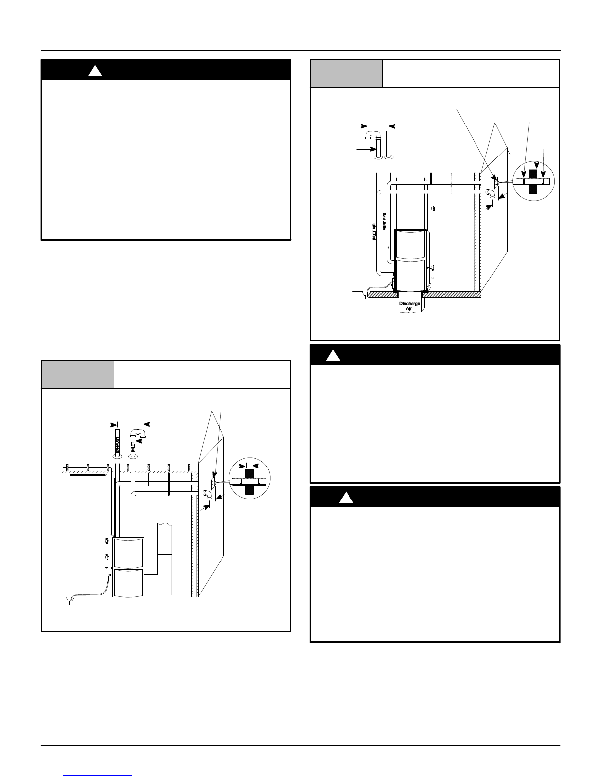
1. Refer to Figure 1 or Figure 2 for typical installation and
basic connecting parts required. Refer to Figure 5 for
typical horizontal direct vent installation and basic
connecting parts required. Supply and return air plenums
and duct are also required.
2. If furnace is a replacement, it is usually best to install the
furnace where the old one was. Choose the location or
evaluate the existing location based upon the minimum
clearance and furnace dimensions (Figure 3).
Figure 1
*8″ (203.2mm) Min.
20′ (6.1m) Max.
in same
atmospheric
zone
Typical Upflow Installation
Aluminum or non-rusting shield recommended. (See Vent
Termination Shielding for dimensions).
Coupling on ends of
Inlet Pipe
(not used on
Single Pipe
model)
exhaust pipe. Total
pipe & coupling out
side structure = 8″
(203.2mm)
Figure 2 Typical Downflow Installation
See Vent Termination
Shielding in Vent Section.
Inlet Pipe
(not used on
Single Pipe
model)
Vent Pipes MUST
be supported Hori
zontally and Vertically
* Increase minimum from 8 (203.2mm) to 18 (457.2mm) for cold climates (sus
tained temperatures 0F (-17C) and below for 24 or more consecutive hours).
!
*8″ (203.2mm) Min.
20′ (6.1m) Max. in
same atmospheric zone
WARNING
Coupling on inside
and outside of wall to
restrain vent pipe
8″ Min.
*8″ (203.2mm) Min.
20′ (6.1m) Max.
in same
atmospheric zone
25−23−33a
CARBON MONOXIDE POISONING HAZARD
Failure to follow this warning could result in
personal injury or death.
Do NOT operate furnace in a corrosive atmosphere
containing chlorine, fluorine or any other damaging
chemicals, which could shorten furnace life.
Refer to Combustion & Ventilation Air section,
Contaminated Combustion Air for combustion air
evaluation and remedy.
Vent Pipes MUST be
supported
Horizontally and
Vertically
* Increase minimum from 8 (203.2mm) to 18 (457.2mm) for cold climates (sus
tained temperatures 0F (-17C) and below for 24 or more consecutive hours).
6
DISCHARGE AIR
!
*8″ (203.2mm) Min.
20′ (6.1m) Max.
in same atmospheric zone
FROZEN AND BURST WATER PIPE HAZARD
Failure to follow this caution may result in property
damage.
Special precautions MUST be made if installing
furnace in an area which may drop below freezing.
This can cause improper operation or damage to
equipment. If furnace environment has the potential
of freezing, the drain trap and drainline must be
protected. The use of electric heat tape or RV
antifreeze is recommended for these installations.
25−23−33
Specifications are subject to change without notice
(See “Condensate Trap Freeze Protection Section”)
Do NOT operate furnace in a corrosive atmosphere
containing chlorine, fluorine or any other damaging
chemicals. Refer to Combustion & Ventilation Air section,
Contaminated Combustion Air.
CAUTION
440 01 1024 04

Installation Requirements
1. Install furnace level.
2. This furnace is NOT to be used for temporary heat of buildings
or structures under construction.
3. Install the vent pipes as short as practical. (See Gas Vent
Installation section).
4. Do NOT install furnace directly on carpeting, tile or other
combustible material other than wood flooring.
5. Maintain clearance for fire safety and servicing. A front
clearance of 24″ (609.6mm) required and 30″ (762mm)
recommended for access to the burner, controls and filter.
See clearance requirements in Figure 3.
6. Use a raised base if the floor is damp or wet at times.
7. Residential garage installations require:
• Burners and ignition sources installed at least 18″
(457.2mm) above the floor.
• Furnace must be located or physically protected from
possible damage by a vehicle.
8. If the furnace is to be suspended from the floor joists in a
basement or a crawl space or the rafters in an attic, it is
necessary to use steel pipe straps or an angle iron frame to
attach the furnace. These straps should be attached to the
furnace with sheet metal screws and to the rafters or joists
with bolts. The preferred method is to use an angle iron frame
bolted to the rafters or joists.
9. Local codes may require a drain pan under the entire furnace
and condensate trap when the furnace is installed in attic
application.
This furnace may be used for construction heat provided that all
the following conditions are met:
• The furnace is permanently installed with all electrical
wiring, piping, venting and ducting installed according to
these installation instructions. A return air duct is provided,
sealed to the furnace casing, and terminated outside the
space containing the furnace. This prevents a negative
pressure condition as created by the circulating air blower,
causing a flame rollout and/or drawing combustion products
into the structure.
• The furnace is controlled by a thermostat. It may not be “hot
wired” to provide heat continuously to the structure without
thermostatic control.
• Clean outside air is provided for combustion. This is to
minimize the corrosive effects of adhesives, sealers and
other construction materials. It also prevents the
entrainment of drywall dust into combustion air, which can
cause fouling and plugging of furnace components.
• The temperature of the return air to the furnace is
maintained between 55° F (13° C) and 80° F (27° C) , with no
evening setback or shutdown. The use of the furnace while
the structure is under construction is deemed to be
intermittent operation per our installation instructions.
• The air temperature rise is within the rated rise range on the
furnace rating plate, and the firing rate has been set to the
rating plate value.
• The filters used to clean the circulating air during the
construction process must be either changed or thoroughly
cleaned prior to occupancy.
• The furnace, ductwork and filters are cleaned as necessary
to remove drywall dust and construction debris from all
HVAC system components after construction is completed.
• After construction is complete, verify furnace operating
conditions including ignition, input rate, temperature rise
and venting according to these instructions.
440 01 1024 04
7
Specifications are subject to change without notice
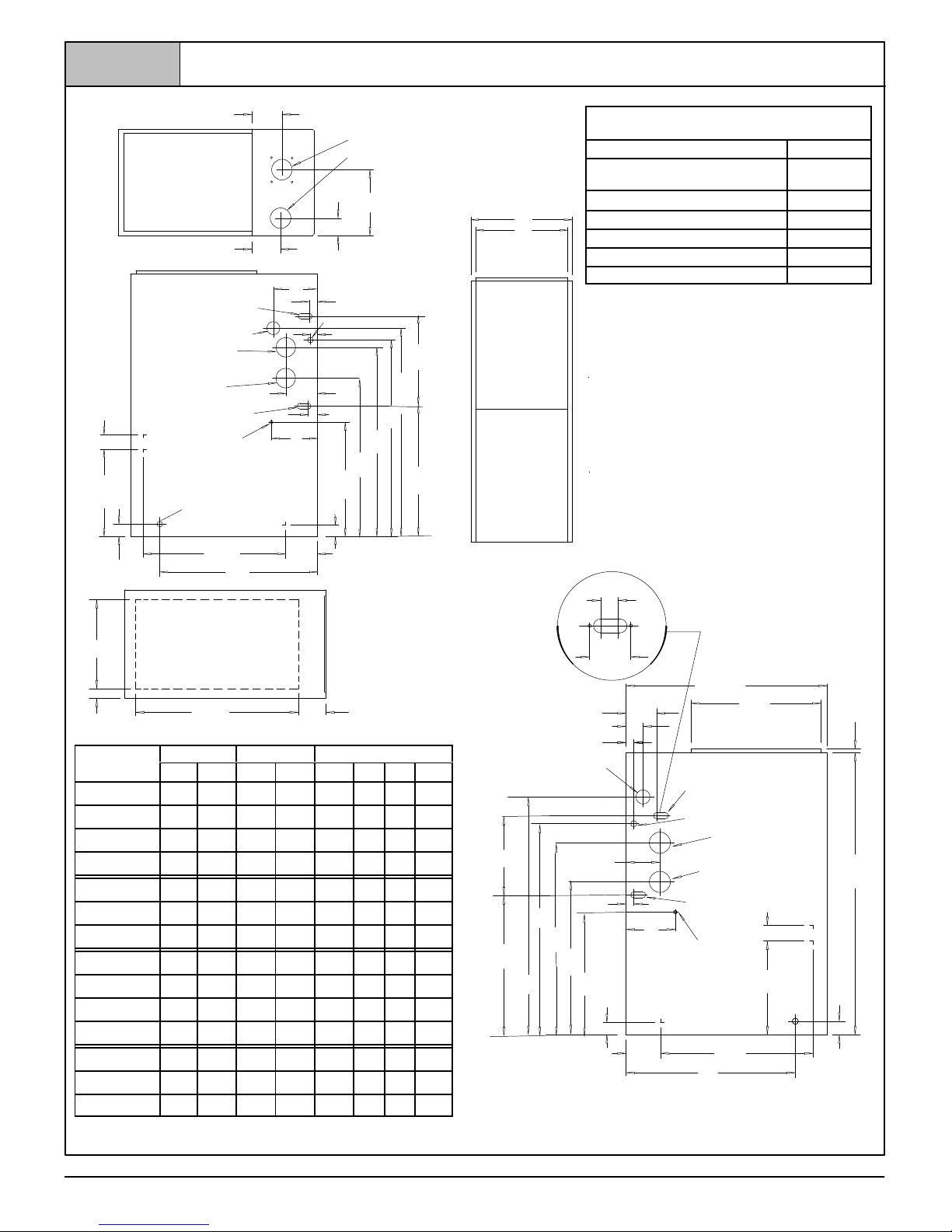
Figure 3
Dimensions & Clearances
21/
(336.6)
4
131/
(57.2)
4
1
(47.6)
7
/
8
TOP
LEFT SIDE
TRAP (KO) (COUNTERFLOW)
GAS
VENT
AIR INTAKE (KO)
(ALTERNATE)
TRAP (KO)
UPFLOW/HORIZONTAL
THERMOSTAT
(KO)
215/
(549.3)
413/
(122.2)
8
24
(609.6)
F
AIR INTAKE
VENT (N9MPD & *9MPD)
COMBUSTIBLE MATERIALS FOR ALL UNITS
REAR 0
FRONT (combustion air openings
MINIMUM CLEARANCES TO
3″ (76.2)
in furnace and in structure)
H
G
A
B
E
11
6
/
ELECTRICAL
(177.5)
16
11/
4
(32)
FRONT
Required For Service
ALL SIDES Of SUPPLY PLENUM 1″ (25.4)
SIDES 0
VENT 0
TOP OF FURNACE 1″ (25.4)
*30″ (762mm) clearance recommended for furnace removal.
Horizontal position: Line contact is permissible only between
(27)
11/
16
16
(177.8)
(123.8)
13/
8
(34.9)
7
241/
(611.2)
175/
16
(439.7)
111/
16
(42.9)
47/
8
(758.8)
283/
(730.3)
16
297/
4
1311/
(347.7)
3111/
(804.9)
8
16
1913/
(503.2)
16
16
lines formed by intersections of top and two sides of furnace
jacket, and building joists, studs or framing.
NOTE: Evaporator “A” coil drain pan dimensions may
vary from furnace duct opening size. Always consult
evaporator specifications for duct size
requirements.
Furnace is designed for bottom return or side
return.
Return air through back of furnace is NOT allowed.
1
/
1
4
(31.7)
*24″ (609.6)
D
C
Unit
Capacity
N9MP1040/050B^^
N9MP1060/075B^^
N9MP1080/100F^^
N9MP1100/125J^^
N9MP2050/075B^^
N9MP2080/100F^^
N9MP2100/125J^^
N9MPD040/050F^^
N9MPD060/075F^^
N9MPD080/100J^^
N9MPD125L^^
*9MPD050/075F^^
*9MPD080/100J^^
*9MPD125L^^
A B
151/
(394)14(356)
151/
(394)14(356)
191/
(486)
223/
(578)
151/
(394)14(356)
191/
(486)
223/
(578)
191/
(486)
191/
(486)
223/
(578)
241/
(622)23(584)
191/
(486)
223/
(578)
241/
(622)23(584)
* Denotes Brand
^^ Cooling Air Flow
BOTTOM
ALL DIMENSIONS − IN(MM)
1 in = 25.4 mm
231/
8
(587.4)
Cabinet Bottom Top
D E F
C
13/
2
2
175/
8
8
(448)
211/
4
4
(540)
2
175/
8
8
(448)
211/
4
4
(540)
175/
8
8
(448)
175/
8
8
(448)
211/
4
4
(540)
2
175/
8
8
(448)
211/
4
4
(540)
2
8
(35)
13/
8
(35)
21/
8
(54)
115/
16
(49)
13/
8
(35)
21/
8
(54)
115/
16
(49)
21/
8
(54)
21/
8
(54)
115/
16
(49)
7
/
16
(11)23(584)
21/
8
(54)
115/
16
(49)
7
/
16
(11)23(584)
125/
(321)
125/
(321)
143/
(375)
183/
(476)
125/
(321)
143/
(375)
183/
(476)
143/
(375)
143/
(375)
183/
(476)
143/
(375)
183/
(476)
8
8
4
4
8
4
4
4
4
4
4
4
37/
8
(98.4)
-- -- -- --
-- -- -- --
-- -- -- --
-- -- -- --
41/
2
-(114)
41/
2
-(114)
41/
2
-(114)
43/
41/
8
2
(111)
(114)
43/
41/
8
2
(111)
(114)
43/
41/
8
2
(111)
(114)
43/
41/
8
2
(111)
(114)
43/
41/
8
2
(111)
(114)
43/
41/
8
2
(111)
(114)
43/
41/
8
2
(111)
(114)
Drawing is representative, but some models may vary
G H
--
--
--
21/
2
(64)
21/
2
(64)
25/
8
(67)
21/
4
(57)
21/
2
(64)
25/
8
(67)
21/
4
(57)
73/
(197)
91/
(241)
113/
(289)
91/
(241)
91/
(241)
113/
(289)
121/
(311)
91/
(241)
113/
(289)
121/
(311)
27/
8
(73)
5
4
/
16
(110)
(60)
23/
8
(27)
11/
16
GAS
281/
(724)
2
181/
(470)
RIGHT SIDE
3
/
4
2
(19)
TYP.
TRAP (COUNTERFLOW)
ELECTRICAL (KO)
AIR INTAKE (KO)
13/
16
(30)
4
2
8
2
2
8
4
2
8
4
297/
(759)
913/
16
(251)
3311/
16
(856)
KO = KnockOut
8
273/
(691)
16
215/
(549)
111/
8
175/
(440)
413/
(122)
16
16
(43)
111/
(43)
16
7
(178)
16
47/
8
(124)
(ALTERNATE)
VENT (KO)
TRAP (KO)
UPFLOW/HORIZONTAL
21/
THERMOSTAT
215/
(549)
24
(610)
4
1
/
19
4
(489)
8
(57)
(KO)
(1016)
17/
8
(48)
25−23−36b
40
8
440 01 1024 04
Specifications are subject to change without notice
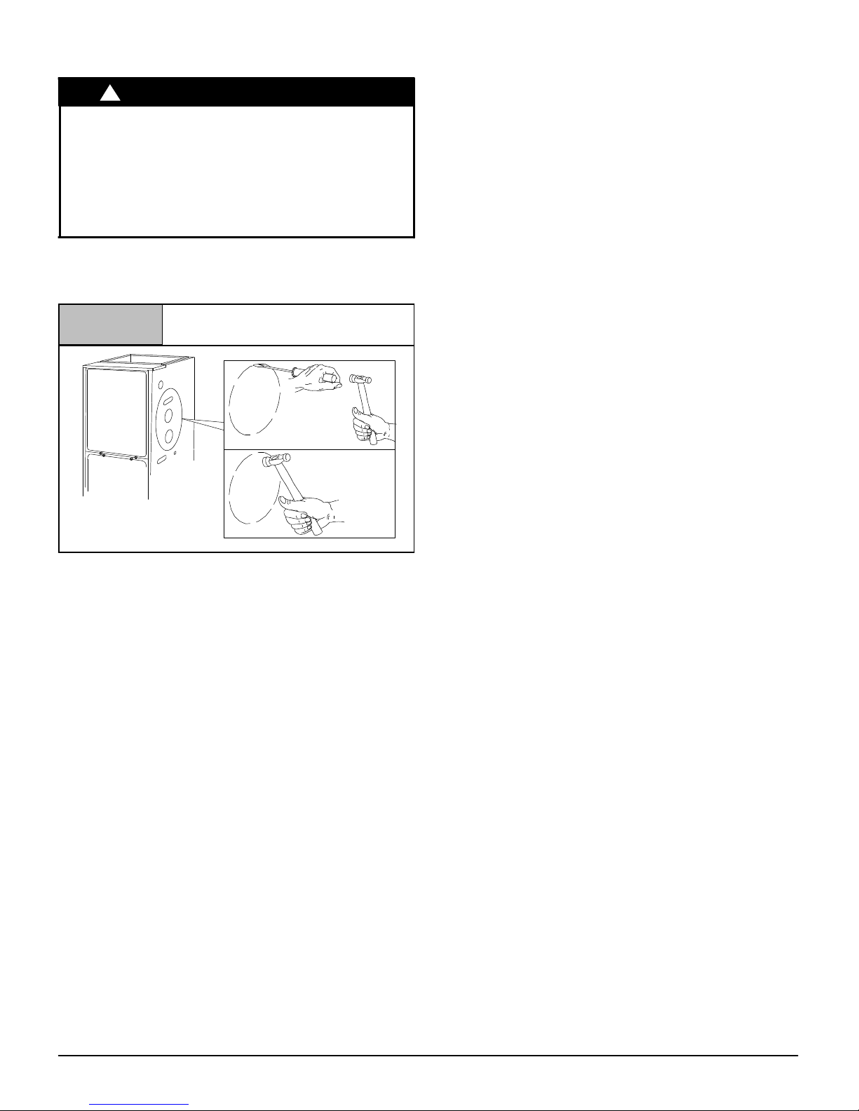
Knock Outs
for upflow and downflow installations or top to bottom for horizontal
installations.
!
CAUTION
CUT HAZARD
Failure to follow this caution may result in personal
injury.
Sheet metal parts may have sharp edges or burrs.
Use care and wear appropriate clothing, safety
glasses and gloves when handling parts and
servicing furnaces.
Use a hammer and screwdriver to strike a sharp blow (See
Figure 4) directly to the knockout tie points or use a hammer in the
upper left corner of the desired knockout. Remove any burrs and
sharp edges.
Hammer and Screwdriver used
Figure 4
25−40−06
NOTE: If a knockout does not come out after two sharp blows, pull
and snip as needed to remove the knockout.
for Knockout
Installation Positions
This furnace can be installed in an upflow, horizontal (either left or
right) or downflow airflow position. DO NOT install this furnace on
its back. For the upflow position, the return air ductwork can be
attached to either the left or right side panel and/or the bottom. For
horizontal and downflow positions, the return air ductwork must be
attached to the bottom. The return air ductwork must never be
attached to the back of the furnace.
Furnace Installation Considerations
The installation of the furnace for a given application will dictate the
position of the furnace, the airflow, ductwork connections, vent and
combustion air piping. Consideration must be given to the
following:
Condensate Trap and Drain Lines
The supplied condensate trap must be attached to the furnace
side panel on either the left or right side. For horizontal
installations, the drain trap is vertically attached to the side panel
below the furnace. A minimum clearance of 6″ (152.4mm) below
the furnace is required for the condensate trap. Downward slope of
the condensate drain line from the condensate trap to the drain
location must be provided. Adequate freeze protection of the drain
trap and the drain line must be provided. See “Condensate Drain
Trap” section for further details.
Leveling
Proper leveling of the furnace must be provided to insure proper
drainage of the condensate from the furnace. The furnace must be
level to within
440 01 1024 04
1
/4″ (6.4mm) from front to back and from side to side
Vent and Combustion Air Connections
For venting information literature, call 931.270.4100 with the
complete model and serial number of the furnace.
Special Venting Requirements for Installations in Canada
Installation in Canada must conform to the requirements of CSA
B149 code. Vent systems must be composed of pipe, fittings,
cements, and primers listed to ULC S636. The special vent fittings
and accessory concentric vent termination kits and accessory
external drain trap have been certified to ULC S636 for use with
those Royal Pipe and IPEX PVC vent components which have
been certified to this standard. In Canada, the primer and cement
must be of the same manufacturer as the vent system – GVS-65
Primer (Purple) for Royal Pipe or IPEX System 636, PVC/CPVC
Primer, Purple Violet for Flue Gas Venting and GVS-65 PVC
Solvent Cement for Royal Pipe or IPEX System 636
Cement for Flue Gas Venting, rated Class IIA, 65 deg C. must be
used with this venting system - do not mix primers and cements
from one manufacturer with a vent system from a different
manufacturer. Follow the manufacturer’s instructions in the use of
primer and cement and never use primer or cement beyond its
expiration date.
The safe operation, as defined by ULC S636, of the vent system is
based on following these installation instructions, the vent system
manufacturer’s installation instructions, and proper use of primer
and cement. All fire stop and roof flashing used with this system
must be UL listed material. Acceptability under Canadian
standard CSA B149 is dependent upon full compliance with all
installation instructions. Under this standard, it is recommended
that the vent system be checked once a year by qualified service
personnel.
The authority having jurisdiction (gas inspection authority,
municipal building department, fire department, etc) should be
consulted before installation to determine the need to obtain a
permit.
(1) System 636 is a trademark of IPEX Inc.
Consignes spéciales pour l’installation de ventillation au
Canada
L’installation faite au Canada doit se conformer aux exigences du
code CSA B149. Ce systême de ventillation doit se composer de
tuyaux, raccords, ciments et apprêts conformes au ULC S636. La
tuyauterie de ventillation des gaz, ses accessoires, le terminal
concentrique mural ainsi que l’ensemble du drain de condensat
extérieur ont été certifiés ULCS 636 pour l’application des
composantes Royal Pipe, IPEX PVC qui sont certifiées à ce
standard. Au Canada, l’apprêt et le ciment doivent être du même
fabricant que le système d’évacuation. L’apprêt GVS-65 (Purple)
et le ciment-solvant GVS-65 doivent être utilisé avec les Royal
Pipe. Système IPEX 636, apprêt PVC/CPVC, Purple pour
évacuation des gaz de combustion et système IPEX 636(1)t,
ciment PVC pour évacuation des gaz de combustion, coté classe
IIA, 65 deg C. doivent être utilisés avec le système d’évacuation
IPEX 636 – Ne pas combiner l’apprêt et le ciment d’un
manufacturier avec un système d’évacuation d’un manufacturier
différent.
Bien suivre les indications du manufacturier lors de l’utilisation de
l’apprêt et du ciment et ne pas utiliser ceux-ci si la date d’expiration
est atteinte.
L’opération sécuritaire, tel que définit par ULC S636, du système
de ventilation est basé sur les instructions d’installation suivantes,
ainsi que l’usage approprié de l’apprêt et ciment. Tout arrët feu et
solin de toit utilisés avec ce système doivent être des matériaux
listés UL. L’acceptation du standard Canadien CSA B419 est
directement relié à l’installation conforme aux instructions ci- haut
Specifications are subject to change without notice
t, PVC
(1)
9
mentionnées. Le standard Canadien recommande l’inspection
par un personel qualifié et ce, une fois par année.
Les autoritées ayant juridiction (inspecteurs de gas, inspecteurs
en bâtiments, département des incendies, etc) devraient être
consultées avant l’installation afin de déterminer si un permis est
requis.
On the N9MPD or *9MPD furnace, the vent and combustion air
pipes attach to the furnace through the top panel for the upflow and
horizontal installations. For the downflow installation, the vent and
combustion air pipes attach to the furnace through the alternate
locations on the furnace side panels.
Note: On the N9MP2 furnace, the vent pipe attaches to the furnace
through the side panels. The combustion air pipe attaches to the
top panel or to the alternate location on the side panel.
On the Single Pipe furnace, the vent pipe attaches to the furnace
through the furnace side panels.
Note: Repositioning of the combustion blower is required for the
vent pipe connection to the furnace through the “right side” panel.
See “Vent and Combustion Air Piping” section for further details.
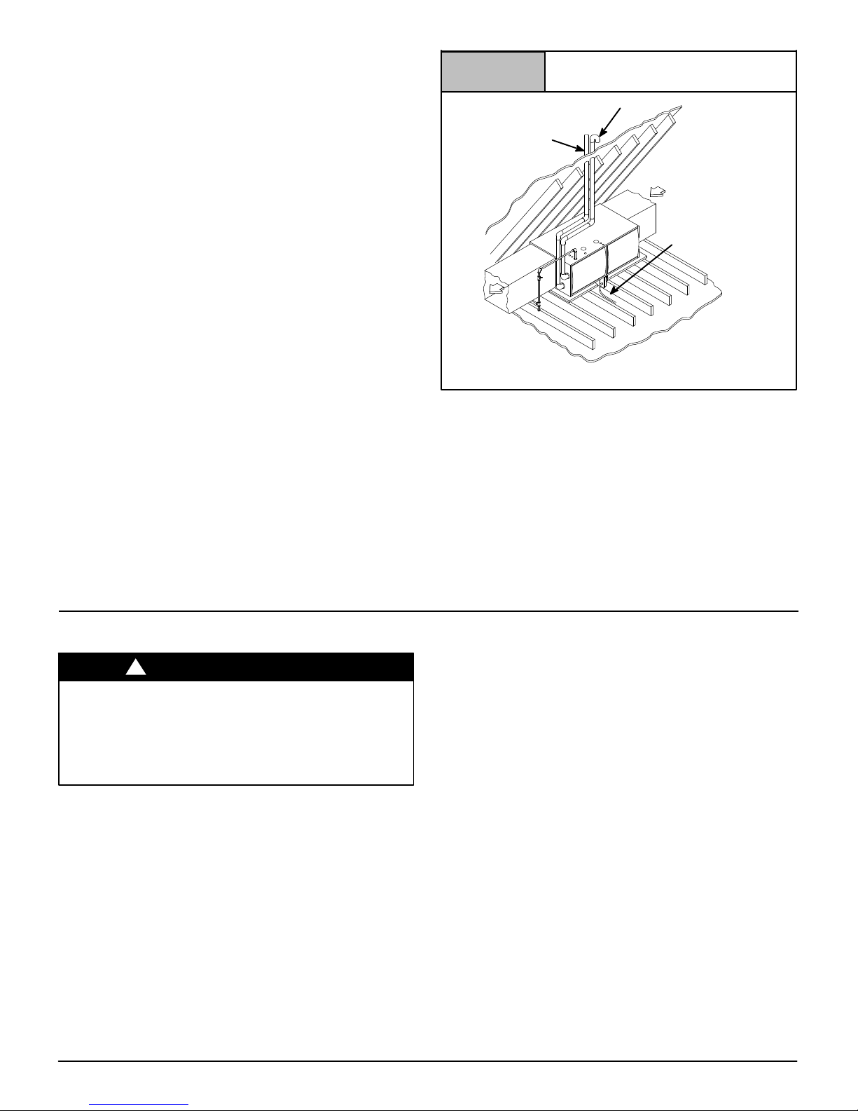
Horizontal Furnace Installation
This furnace can be installed horizontally in an attic, basement,
crawl space, alcove, or suspended from a ceiling in a basement or
utility room . See Figure 5. Do not install furnace on its back or in
the reverse airflow positions as safety control operation will be
adversely affected.
If the furnace is to be installed in a crawl space, consult local
codes. A suitable concrete pad or blocks are recommended for
crawl space installation on the ground.
NOTE: 6″ (152.4mm) bottom clearance required for condensate
trap.
24″(609.6mm) between the front of the furnace and adjacent
construction or other appliances MUST be maintained for service
clearance. 30″ (762mm) inches is required to remove furnace.
Figure 5
NOTE: 6 (152.4mm)bottom clearance required for condensate trap.
Auxiliary drain pan is required if over a finished living space.
Keep all insulating materials clear from louvered door. Insulating
materials may be combustible.
The horizontal furnaces may be installed directly on combustible
wood flooring or supports as long as all required furnace
clearances are met. See Figure 5.
This furnace MUST NOT be installed directly on carpeting or tile or
other combustible material other than wood flooring or supports.
For horizontal installation over a finished living space. A field
fabricated auxiliary drain pan with drain pipe is required to prevent
damage by overflow due to blocked condensate drain.
Typical Horizontal Installation
Attic
Inlet Pipe (not used on Single Pipe model)
Vent
Pipe
Condensate
Trap
25−23−34
Combustion & Ventilation Air
For Single Pipe Installation
!
WARNING
CARBON MONOXIDE POISONING HAZARD
Failure to follow this warning could result in
personal injury or death.
Provide adequate combustion and ventilation air.
Use methods described here to provide
combustion and ventilation air.
Furnaces require ventilation openings to provide sufficient air for
proper combustion and ventilation of flue gases. All duct or
openings for supplying combustion and ventilation air must
comply with the gas codes, or in the absence of local codes, the
applicable national codes.
Combustion and ventilation air must be supplied in accordance
with one of the following:
Note: The Combustion & Ventilation Air Section in this document,
uses tables and information from the ANSI Z223.1/NFPA
54. For use in Canada, use CSA B149.1 for this information.
1. Section 9.3, Air for Combustion and Ventilation, of the National
Fuel Gas Code, (NFGC), ANSI Z223.1/NFPA 54−2009 in the
U.S.,
2. Sections 8.2, 8.3, 8.5, 8.6, 8.7, and 8.8 of National Standard of
Canada, Natural Gas and Propane Installation Code
(NSCNGPIC), CSA B149.1−05 in Canada,
3. Applicable provisions of the local building code.
This furnace can NOT be common vented or connected to any
type B, BW or L vent or vent connector, nor to any portion of a
factory−built or masonry chimney. Multistory venting is NOT
permitted. If this furnace is replacing a previously common-vented
furnace, it may be necessary to resize the existing vent and
chimney to prevent oversizing problems for the other remaining
appliance(s). See “Venting and Combustion Air Check” in this
section. This furnace MUST be vented to the outside.
When the installation is complete, check that all appliances have
adequate combustion air and are venting properly. See Venting
And Combustion Air Check in “Gas Vent Installation” Section in
this manual.
Outdoor Combustion Air Method
A space having less than 50 cubic feet per 1,000 BTUH (4.8 cubic
meters per kW) input rating for all gas appliances installed in the
space requires outdoor air for combustion and ventilation.
Air Openings and Connecting Ducts
1. Total input rating for all gas appliances in the space MUST be
considered when determining free area of openings.
2. Connect ducts or openings directly to the outdoors.
3. When screens are used to cover openings, the openings
MUST be no smaller than
4. The minimum dimension of air ducts MUST NOT be less than
3″ (76.2mm).
1
/4″ (6.4mm) mesh.
10
440 01 1024 04
Specifications are subject to change without notice
5. When sizing a grille, louver, or screen use the free area of
opening. If free area is NOT stamped or marked on grill or
louver, assume a 20% free area for wood and 60% for metal.
Screens shall have a mesh size not smaller than
1
/4″ (6.4mm).
Requirements
1. Provide the space with sufficient air for proper combustion and
ventilation of flue gases using horizontal or vertical ducts or
openings.
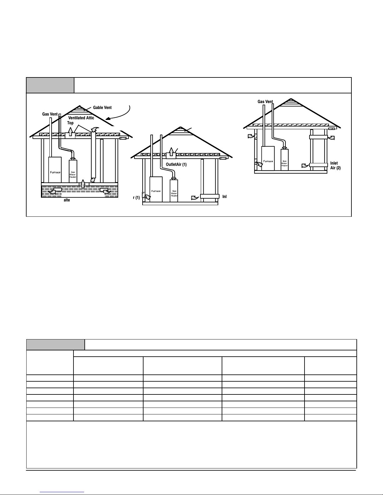
2. Figure 6 illustrates how to provide combustion and ventilation
air when two permanent openings, one inlet and one outlet,
are used.
a. One opening MUST commence within 12″ (304.8mm) of
the floor and the second opening MUST commence
within 12″ (304.8mm) of the ceiling.
b. Size openings and ducts per Table 1.
Figure 6
Outside Air (This is ONLY a guide. Subject to codes of country having jurisdiction.)
This installation NOT approved in Canada
Gable Vent
Gas Vent
c. Horizontal duct openings require 1 square inch of free
area per 2,000 BTUH (11 cm
Ventilated Attic
Top Above Insulation
Outlet Air (1)
Ventilated Crawl Space
alternate Inlet Air (1)
alternate Inlet Air (1)
Soffit Vent
2
/kW) of combined input for
all gas appliances in the space (see Table 1).
d. Vertical duct openings or openings directly
communicating with the outdoors require 1 square inch
of free area per 4,000 BTUH (5.5 cm
input of all gas appliances in the space (see Table 1).
3. When one permanent outdoor opening is used, the opening
requires:
a. 1 sq. in of free area per 3,000 BTUH (7 cm
combined input of all gas appliances in the space (see
Table 1) and
b. not less than the sum of the areas of all vent connectors
in the space.
The opening shall commence within 12″ (304.8mm) of the top of
the enclosure. Appliances shall have clearances of at least 1″
(25.4mm) from the sides and back and 6″ (152.4mm) from the
front. The opening shall directly communicate with the outdoors or
Table 1
BTUH (kW)
Input
Rating
40,000 (11.72) 20 sq. in. (129 cm2) 13.34 sq. in. (86 cm2) 10 sq. in. (65 cm2) 4″ (101.6mm)
50,000 (14.65) 25 sq. in. (161 cm2) 16.7 sq. in. (108 cm2) 12.5 sq. in. (81 cm2) 4″ (101.6mm)
60,000 (17.58) 30 sq. in. (194 cm2) 20 sq. in. (129 cm2) 15 sq. in. (97 cm2) 4″ (101.6mm)
75,000 (21.98) 37.5 sq. in. (242 cm2) 25 sq. in. (161 cm2) 18.75 sq. in. (121 cm2) 5″ (127mm)
80,000 (23.45) 40 sq. in. (258 cm2) 26.7 sq. in. (172 cm2) 20 sq. in. (129 cm2) 5″ (127mm)
100,000 (29.31) 50 sq. in. (322 cm2) 33.3 sq. in. (215 cm2) 25 sq. in. (161 cm2) 6″ (152.4mm)
125,000 (36.63) 62.50 sq. in. (403 cm2) 41.7 sq. in. (269 cm2) 31.25 sq. in. (202 cm2) 7″ (177.8mm)
EXAMPLE: Determining Free Area
Furnace
100,000
29.31
Furnace
100,000
29.31
440 01 1024 04
Free Area
Two Horizontal Ducts
BTUH (kW)
sq. in./2,000(1 cm2/.09)
Water Heater
+
+
30,000
8.8
Water Heater
30,000
8.8
Gable Vent
Soffit Vent
Inlet
Air (2)
Inlet
Air (1)
Gas Vent
Ventilated Attic
Top Above Insulation
OutletAir (1)
shall communicate through a vertical or horizontal duct to the
outdoors or spaces (crawl or attic) that freely communicate with
the outdoors.
4. Combination of Indoor and Outdoor Air shall have:
2
/kW) for combined
a. Indoor openings that comply with the Indoor
Combustion Air Method below and
b. Outdoor openings located as required in the Outdoor
Combustion Air Method above and
2
/kW) for
c. Outdoor openings sized as follows.
1) Calculate the Ratio of all Indoor Space volume
divided by required volume for Indoor Combustion Air
Method.
2) Outdoor opening size reduction Factor is 1 minus the
Ratio in 1) above.
3) Minimum size of Outdoor openings shall be the size
required in Outdoor Combustion Air Method above
multiplied by reduction Factor.
Minimum Free Area Required for Each Opening or Duct to Outdoors
Single Opening
BTUH (kW)
sq. in./3,000 (1 cm2/.135)
Total Input
=
=
Specifications are subject to change without notice
(130,000 ÷ 4,000)
(38.11 ÷ .18)
Total Input
(130,000 ÷ 2,000)
(38.11 ÷ .09)
= 32.5 Sq. In. Vertical
= 210 cm2 Vertical
= 65 Sq. In. Horizontal
= 423 cm2 Horizontal
Gas Vent
Outlet
Air (1)
Inlet
Air (1)
Minimum One Inlet and One Outlet Air Supply is Required
May be in any Combination Shown
Inlet Air Opening must be within 12″ (304.8mm) of floor
Outlet Air Opening must be within 12″ (304.8mm) of ceiling
(1) 1 Square Inch per 4000 BTUH
(2) 1 Square Inch per 2000 BTUH
Two Vertical Ducts or Openings
BTUH (kW)
sq. in./4,000(1 cm2/.18)
sq. in./4,000(6.5cm2/.18)
Outlet
Air (2)
Inlet
Air (2)
Round Duct
BTUH (kW)
11
Indoor Combustion Air
!
WARNING
CARBON MONOXIDE POISONING HAZARD
Failure to follow this warning could result in
personal injury or death.
Most homes will require additional air from
outdoors for combustion and ventilation. A space
with at least 50 cubic feet per 1,000 BTUH (4.8 cubic
meters per kW) input rating or homes with tight
construction may need outdoor air, supplied
through ducts, to supplement air infiltration for
proper combustion and ventilation of flue gases.
Standard and Known-Air-Infiltration Rate Methods
NFPA & AGA
Indoor air is permitted for combustion and ventilation, if the
Standard or Known−Air−Infiltration Rate Method is used.
The Standard Method may be used, if the space has no less
volume than 50 cubic feet per 1,000 BTUH (4.8 cubic meters per
kW) input rating for all gas appliances installed in the space. The
standard method permits indoor air to be used for combustion and
ventilation air.
The Known Air Infiltration Rate Method shall be used if the
infiltration rate is known to be less than 0.40 air changes per hour
(ACH) and equal to or greater than 0.10 ACH. Infiltration rates
greater than 0.60 ACH shall not be used. The minimum required
volume of the space varies with the number of ACH and shall be
determined per Table 2 or Equations 1 and 2. Determine the
minimum required volume for each appliance in the space, and
add the volumes together to get the total minimum required
volume for the space.
!
WARNING
CARBON MONOXIDE POISONING HAZARD
Failure to follow this warning could result in
personal injury or death.
An unconfined space or homes with tight
construction may not have adequate air infiltration
for proper combustion and ventilation of flue gases.
Most homes will require additional air.
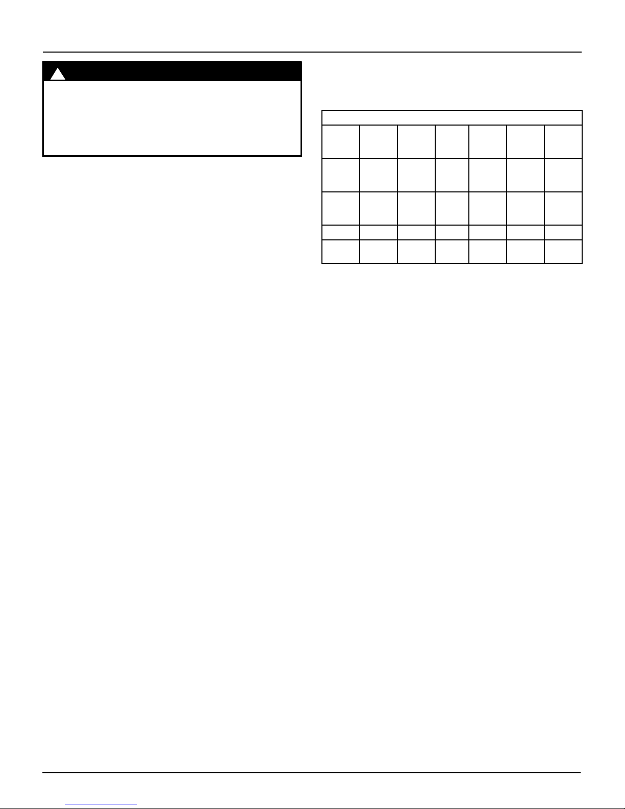
Table 2
30,000 BTU
ACH
0.60 1,050 (29.7) 1,400 (39.2) 1,750 (49) 1,250 (35) 1,875 (52.5) 2,500 (70) 3,125 (87.5)
0.50 1,260 (35.3) 1,680 (47.04) 2,100 (58.8) 1,500 (42) 2,250 (63) 3,000 (84) 3,750 (105)
0.40 1,575 (44.1) 2,100 (58.8) 2,625 (73.5) 1,875 (52.5) 2,813 (78.8) 3,750 (105) 4,688 (131.3)
0.30 2,100 (58.8) 2,800 (78.4) 3,500 (98) 2,500 (70) 3,750 (105) 5,000 (140) 6,250 (175)
0.20 3,150 (88.2) 4,200 (117.6) 5,250 (147) 3,750 (105) 5,625 (157.5) 7,500 (210) 9,375 (262.5)
0.10 6,300 (176.4) 8,400 (235.2) 10,500 (294) 7,500 (210) 11,250 (315) 15,000 (420) 18,750 (525)
0.00 NP NP NP NP NP NP NP
ACH = Air Changes per Hour
NP = Not Permitted
Table 2 Minimum Space Volumes were determined by using the
following equations from the National Fuel Gas Code ANSI
Z223.1/NFPA 54−2009, 9.3.2.2:
1. For appliances other than fan−assisted appliances (such
as a draft hood−equipped water heater), calculate using the
following equation:
Required Vol ume
Required Vol ume
2. For fan−assisted appliances (such as this furnace),
calculate using the following equation:
Required Vol ume
Required Vol ume
(8,790 kW)
MINIMUM SPACE VOLUME FOR 100% COMBUSTION AND VENTILATION AIR FROM INDOORS
Other Than Fan-Assisted Total Fan-assisted Total
other
other
21 ft
ACH
59 m
ACH
40,000 BTU
(11,720 kW)
3
(
3
(
1000 BTUH
I
other
I
other
.293 kW
50,000 BTU
(14,650 kW)
)
)
50,000 BTU
(14,650 kW)
3
3
ft
(m
)
where:
I
= all appliances other than fan−assisted input in BTUH
other
I
= fan−assisted appliance input in BTUH
fan
ACH = air change per hour (percent of volume of space
3. For purposes of this calculation, an infiltration rate greater
than 0.60 ACH shall not be used in the equations above.
The following requirements apply to the Standard Method and to
the Known Air Infiltration Rate Method.
75,000 BTU
(21,975 kW)
exchanged per hour, expressed as a decimal)
• Adjoining rooms can be considered part of a space, if there
are no closable doors between rooms.
• Combining spaces on the same story. Each opening shall
have a minimum free area of at least 1 in.
2
cm
/kW) of the total input rating of all appliances in the space
but not less than 100 in.
commence within 12 in. (304.8 mm) of the top, and one
opening shall commence within 12 in. (304.8 mm) of the
bottom, of the enclosure. The minimum dimension of air
openings shall not be less than 3 in (76.2 mm).
on different stories shall be considered as communicating
spaces where such spaces are connected by one or more
(
(
I
fan
1000 BTUH
I
fan
.293 kW
)
)
• Combining spaces in different stories. The volumes of spaces
15 ft
ACH
.42 m
ACH
3
fan
fan
3
2
(645 cm2). One opening shall
100,000 BTU
(29,300 kW)
2
/1,000 BTUH (22
125,000 BTU
(36,625 kW)
12
440 01 1024 04
Specifications are subject to change without notice
openings in doors or floors having a total minimum free area
2
of 2 in.
appliances.
/1,000 BTUH (44 cm2/kW) of total input rating of all
• An attic or crawl space may be considered a space that freely
communicates with the outdoors provided there are adequate
ventilation openings directly to outdoors. Openings MUST
remain open and NOT have any means of being closed off.
Ventilation openings to outdoors MUST be at least 1 square
inch of free area per 4,000 BTUH (5.5 cm
rating for all gas appliances in the space.
2
/kW) of total input
• In spaces that use the Indoor Combustion Air Method,
infiltration should be adequate to provide air for combustion,
ventilation and dilution of flue gases. However, in buildings
with unusually tight construction, additional air MUST be
provided using the methods described in section titled
Outdoor Combustion Air Method:
• Unusually tight construction is defined as Construction with:
1. Walls and ceilings exposed to the outdoors have a
continuous, sealed vapor barrier. Openings are
gasketed or sealed and
2. Doors and openable windows are weather stripped and
3. Other openings are caulked or sealed. These include
joints around window and door frames, between sole
plates and floors, between wall−ceiling joints, between
wall panels, at penetrations for plumbing, electrical and
gas lines, etc.
Ventilation Air
Some provincial codes and local municipalities require ventilation
or make−up air be brought into the conditioned space as
replacement air. Whichever method is used, the mixed return air
temperature across the heat exchanger MUST not fall below 60°
so that flue gases will not condense excessively in the heat
exchanger. Excessive condensation will shorten the life of the heat
exchanger and possibly void your warranty.
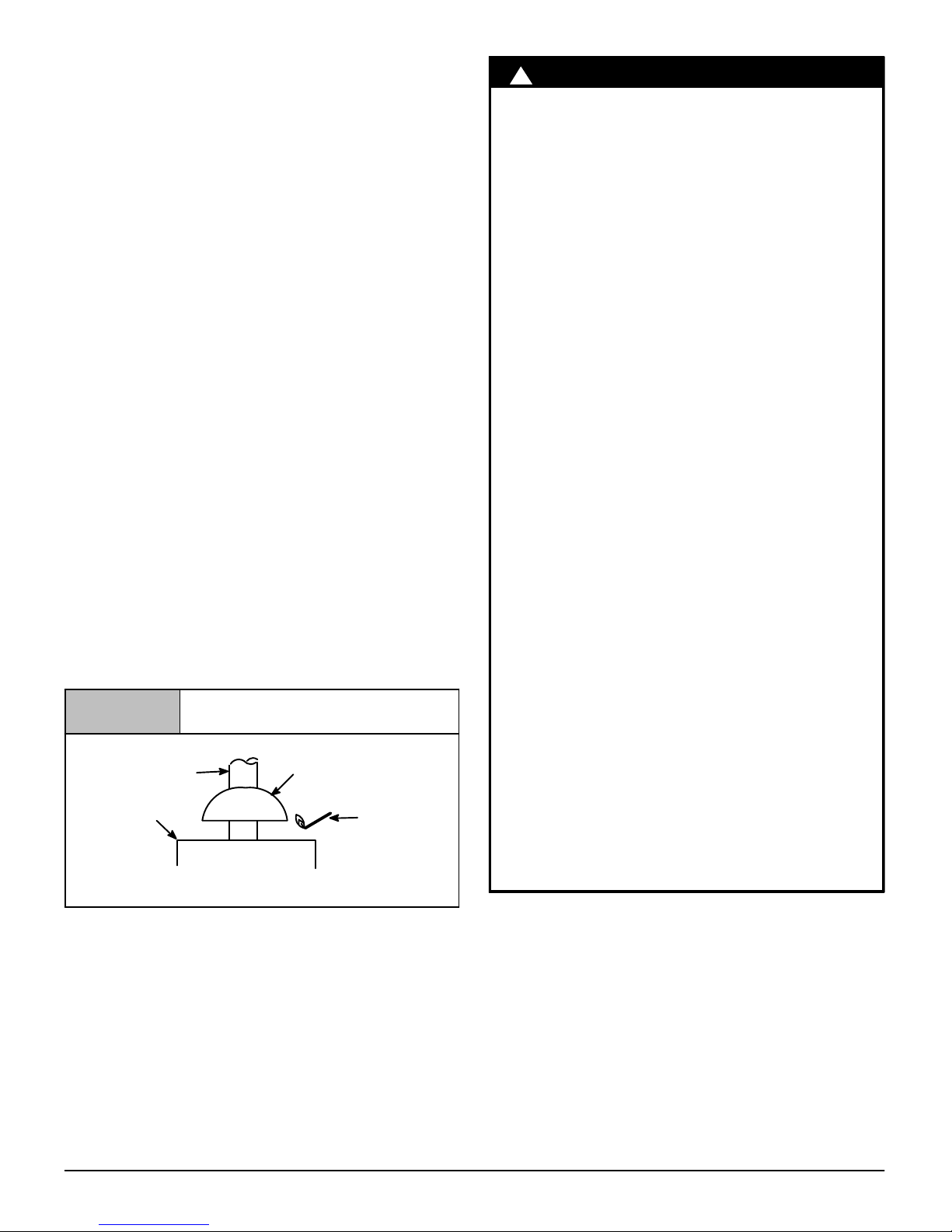
Venting and Combustion Air Check
Figure 7
Vent Pipe
Typical Gas
Water Heater
If flame pulls towards draft hood, this indicates sufficient
venting.
NOTE: When an existing Category I furnace is removed or
replaced, the original venting system may no longer be sized to
properly vent the attached appliances, and to make sure there is
adequate combustion air for all appliances, MAKE THE
FOLLOWING CHECK.
Vent Check
Draft Hood
Match
!
WARNING
CARBON MONOXIDE POISONING HAZARD
Failure to follow the steps outlined below for each
appliance connected to the venting system being
placed into operation, could result in carbon
monoxide poisoning or death:
The following steps shall be followed for each
appliance connected to the venting system being
placed into operation, while all other appliances
connected to the venting system are not in
operation:
1. Seal any unused openings in the venting system.
2. Inspect the venting system for proper size and horizontal
pitch, as required in the National Fuel Gas Code, ANSI
Z223.1/NFPA 54 or CSA B149.1, Natural Gas and
Propane Installation Code and these instructions. Deter-
mine that there is no blockage or restriction, leakage,
corrosion and other deficiencies which could cause an
unsafe condition.
3. As far as practical, close all building doors and windows
and all doors between the space in which the appliance(s)
connected to the venting system are located and other
spaces of the building.
4. Close fireplace dampers.
5. Turn on clothes dryers and any appliance not connected
to the venting system. Turn on any exhaust fans, such as
range hoods and bathroom exhausts, so they are
operating at maximum speed. Do not operate a summer
exhaust fan.
6. Follow the lighting instructions. Place the appliance being
inspected into operation. Adjust the thermostat so
appliance is operating continuously.
7. Test for spillage from draft hood equipped appliances at
the draft hood relief opening after 5 minutes of main burner operation. Use the flame of a match or candle.
(Figure 7)
8. If improper venting is observed, during any of the above
tests, the venting system must be corrected in
accordance with the National Fuel Gas Code, ANSI
Z223.1/NFPA 54 and/or CSA B149.1, Natural Gas and
Propane Installation Code.
9. After it has been determined that each appliance
connected to the venting system properly vents when
tested as outlined above, return doors, windows, exhaust
fans, fireplace dampers and any other gas−fired burning
appliance to their previous conditions of use.
For Two Pipe Installation
This furnace can NOT be common vented or connected to any
type B, BW or L vent or vent connector, nor to any portion of a
factory−built or masonry chimney. If this furnace is replacing a
previously common-vented furnace, it may be necessary to resize
the existing vent and chimney to prevent oversizing problems for
the other remaining appliance(s). See “Venting and Combustion
Air Check” in this section. This furnace MUST be vented to the
outside.
440 01 1024 04
13
Specifications are subject to change without notice
Vent and Combustion Air Piping
!
WARNING
CARBON MONOXIDE POISONING HAZARD
Failure to follow this warning could result in
personal injury or death.
Use methods described here to provide combustion
and ventilation air.
Single Pipe (N9MP1 Models)
This furnace is certified as a Category IV appliance. This furnace
requires ventilation openings to provide air for proper combustion
and ventilation of flue gases. All duct or openings for supplying
combustion and ventilation air must comply with the gas codes or
in absence of local codes, the applicable national codes.
When the installation is complete, see the “Venting and
Combustion Air Check” in this manual.
Dual Certified (N9MP2, N9MPD and *9MPD
Models)
This furnace is certified as a Category IV appliance. This furnace
can be installed as a direct vent furnace using outside air for
combustion or the furnace can use air from inside the structure for
combustion. The INLET air pipe is optional. If combustion air
comes from inside the structure, adequate make up air MUST be
provided to compensate for oxygen burned. See Confined Space
Installation in the Combustion and Ventilation Air chapter. If
combustion air is drawn from outside the structure, it MUST be
taken from the same atmospheric pressure zone as the vent pipe.
Contaminated Combustion Air
Installations in certain areas or types of structures will increase the
exposure to chemicals or halogens that may harm the furnace.
The following areas or types of structures may contain or have
exposure to the substances listed below. The installation must be
evaluated carefully as it may be necessary to provide outside air
for combustion.
• Commercial buildings.
• Buildings with indoor pools.
• Furnaces installed in laundry rooms.
• Furnaces installed in hobby or craft rooms.
• Furnaces installed near chemical storage areas.
• Permanent wave solutions for hair.
• Chlorinated waxes and cleaners.
• Chlorine based swimming pool chemicals.
• Water softening chemicals.
• De−icing salts or chemicals.
• Carbon tetrachloride.
• Halogen type refrigerants.
• Cleaning solvents (such as perchloroethylene).
• Printing inks, paint removers, varnishes, etc.
• Hydrochloric acid.
• Sulfuric Acid.
• Solvent cements and glues.
• Antistatic fabric softeners for clothes dryers.
• Masonry acid washing materials.
Vent and Combustion Air Piping Guidelines
This furnace is approved for venting with Schedule 40 PVC,
CPVC, ABS fittings, and Cellular Core and SDR−26 PVC pipe.
Applicable ASTM Standards for Vent Materials
Materials
ABS D1527 __ F628
PVC D1785 D2241 F891
CPVC F441 F442 −− F438 −− F493
ABS to
PVC
NOTE: 1) In Canada, all pipe, fittings & cements must conform to
applicable CSA standards or to local codes having jurisdiction.
the specific venting material.
solvent cement that meets the requirements of ASTM D3138.
cementing plastic pipe and fittings.
NOTE: In order to create a seal that allows future removal of pipe,
RTV sealant MUST be used on the inlet pipe where it joins to the
furnace.
NOTE: All vent piping MUST be installed in compliance with local
codes or ordinances, these instructions, good trade practices, and
codes of country having jurisdiction.
1. Determine the best routing and termination for the vent pipe
2. Determine the size required for the vent pipe and air inlet
3. Loosely assemble all venting parts without adhesive (pipe
4. Furnace shall be installed so as to prevent the accumulation
5. Use of vertical piping is preferred because there will be
6. The vertical vent pipe MUST be supported so that no weight
7. Exhaust vent piping or air inlet piping diameter MUST NOT
8. All exhaust vent piping from the furnace to termination
9. Use DWV type long radius elbows whenever possible, as
10. All horizontal pipe runs MUST be supported at least every
Sch. 40
Pipe
−− −− −− −− −− D3138
2) Only use solvent cements that are marked for use with
3) ABS to PVC transition joints REQUIRE a special
4) Refer to ASTM D2855 for general procedure to use for
and air inlet pipe by referring to all of the instructions and
guidelines in this Section.
pipe.
joint cement) for correct fit before final assembly.
of condensate.
some moisture in the flue gases that may condense as it
leaves the vent pipe (See Instruction For Horizontal Vents).
is allowed to rest on the combustion blower.
be reduced.
MUST slope upwards. A minimum of
(6.4mm per 304.8mm) of run is required to properly return
condensate to the furnace drain system.
they provide for the minimum slope on horizontal runs and
they provide less resistance in the vent system. If DWV
elbows cannot be used, use two, 45° elbows when possible.
On horizontal runs the elbows can be slightly misaligned to
provide the correct slope.
five feet with galvanized strap or other rust resistant
material. NO sags or dips are permitted.
SDR
Pipe
Cell
Core
Pipe
Fittings Primer
D2468
&
D2661
D2466
&
D2665
−− D2235
F656 D2564
1
/4″ per foot per
Solv.
Cement
14
440 01 1024 04
Specifications are subject to change without notice
11. All vertical pipe runs MUST be supported every six feet
(1.8m) where accessible.
12. The minimum vent length is 5′ (1.5m) of PVC.
13. The piping can be run in the same chase or adjacent to
supply or vent pipe for water supply or waste plumbing. It
can also be run in the same chase with a vent from another
90+ furnace.
NOTE: In NO case can the piping be run in a chase where
temperatures can exceed 140° F(60°C). or where radiated
heat from adjacent surfaces would exceed 140° F(60°C).
14. The vent outlet MUST be installed to terminate in the same
atmospheric pressure zone as the combustion air inlet.
15. The vent system can be installed in an existing unused
chimney provided that:
• Both the exhaust vent and air intake run the length of the
chimney.
• No other gas fired appliance or fireplace (solid fuel) is
vented into the chimney.
• The top of the chimney MUST be sealed flush or crowned
up to seal against rain or melting snow so ONLY the piping
protrudes.
• The termination clearances shown in Figure 8 & Figure 9
are maintained.
16. Furnace applications with vertical vents requiring vent
diameter increaser fittings must have increaser fittings
installed in vertical portion of the vent. Condensate will be
trapped in the vent if the vent diameter is increased prior to
having an elbow turned upward. This could cause nuisance
tripping of the pressure switch.
Combustion Air and Vent Piping Insulation
Guidelines
NOTE: Use closed cell, neoprene insulation or equivalent. If
Fiberglass or equivalent insulation is used it must have a vapor
barrier. Use R values of 7 up to 10′ (3.1m), R−11 if exposure
exceeds 10′(3.1m). If Fiberglass insulation is used, exterior to the
structure, the pipe MUST be boxed in and sealed against
moisture.
1. When the vent or combustion air pipe height above the roof
exceeds 30″ (762mm) or if an exterior vertical riser is used
on a horizontal vent to get above snow levels, the exterior
portion MUST be insulated.
2. When combustion air inlet piping is installed above a
suspended ceiling, the pipe MUST be insulated with
moisture resistant insulation such as Armaflex or other
equivalent type of insulation.
3. Insulate combustion air inlet piping when run in warm,
humid spaces.
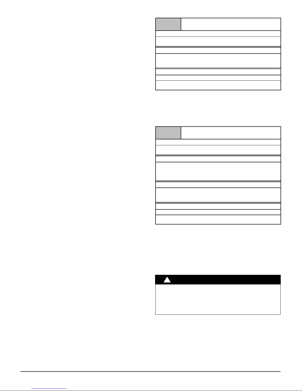
Sizing Combustion Air and Vent Pipe
Consult Table 3 or Table 4 to select the proper diameter exhaust
and combustion air piping. Exhaust and combustion air piping is
sized for each furnace Btuh size based on total linear vent length
(on inlet or outlet side), and number of 90° elbows required. Two
45° elbows can be substituted for one 90° elbow. The elbow or
elbows used for vent termination outside the structure ARE
counted, including elbows needed to bring termination above
expected snow levels. The elbow inside the furnace on the
N9MPD and *9MPD IS NOT included in the count.
Table 3
40,000, 50,000, 60,000, 75,000 & 80,000 Btuh Furnaces
40′ (12.2m) & (5) 90° elbows with 2″ (50.8mm) PVC pipe or
70′ & (5) 90° elbows with 3″ (76.2mm) PVC pipe
40′ (12.2m) & (5) 90° elbows with 3″ (76.2mm) PVC pipe or
70′ & (5) 90° elbows with 3″ (76.2mm) PVC pipe &
40′ & (5) 90° elbows with 3″ (76.2mm) PVC pipe
The minimum vent length is 5 (1.5m) of PVC. Elbows are DWV
Long Radius Type for 2″ (50.8mm) and 3″ (76.2mm) vents.
If more than five elbows are required, REDUCE the length of
both the inlet and exhaust pipes 5′ (1.5m) for each additional
elbow used. If less than five elbow are required, the length
can be INCREASED by 5′ (1.5m) for each additional elbow
NOT used.
NOTE: It is allowable to use larger diameter pipe and fitting than
shown in the tables but not smaller diameters than shown.
N9MP1, N9MPD & *9MPD Models
Long Vent Kit (See Tech. Manual)
Table 4
50,000 & 80,000 Btuh Furnaces
40′ (12.2m) & (5) 90° elbows with 2″ (50.8mm) PVC pipe or
70′ (21.3m) & (5) 90° elbows with 3″ (76.2mm) PVC pipe
25′ & (3) 90° elbows with 2″ (50.8mm) PVC pipe or
40′ (12.2m) & (5) 90° elbows with 2″ (50.8mm) PVC pipe &
70′ (21.3m) & (5) 90° elbows with 3″ (76.2mm) PVC pipe
40′ (12.2m) & (5) 90° elbows with 3″ (76.2mm) PVC pipe or
70′ (21.3m) & (5) 90° elbows with 3″ (76.2mm)PVC pipe &
40′ (12.2m) & (5) 90° elbows with 3″ (76.2mm) PVC pipe
The minimum vent length is 5 (1.5m) of PVC. Elbows are DWV
Long Radius Type for 2″ (50.8mm) and 3″ (76.2mm) vents.
If more than five elbows are required, REDUCE the length of
both the inlet and exhaust pipes 5′ (1.5m) for each additional
elbow used. If less than five elbows are required, the length
can be INCREASED by 5′ (1.5m) for each additional elbow
NOT used.
NOTE: It is allowable to use larger diameter pipe and fitting than
shown in the tables but not smaller diameters than shown.
For concentric vent pipe diameter see Concentric
Termination tables in this manual.
Long Vent Kit (See Tech. Manual) or
Long Vent Kit (See Tech. Manual)
Pipe Diameter Table
100,000 Btuh Furnace
125,000 Btuh Furnace
Pipe Diameter Table
N9MP2 Models
75,000 Btuh Furnaces
100,000 Btuh Furnace
125,000 Btuh Furnace
Vent Termination Clearances
!
CARBON MONOXIDE POISONING.
Failure to follow this warning could result in
personal injury or death.
Inlet and outlet pipes may NOT be vented directly
above each other.
1. Determine termination locations based on clearances
specified in following steps and as shown in Figure 8,
Figure 9, Figure 22, through Figure 24.
For concentric vent termination clearances, refer to
Concentric Termination Kit instructions.
2. For Single Pipe Installation, models N9MP1, N9MP2,
N9MPD or *9MPD, refer to Figure 9 for vent termination
clearances.
3. For Direct Vent Installation, models N9MP2, N9MPD or
*9MPD, refer to Figure 8 for vent termination clearances.
WARNING
440 01 1024 04
15
Specifications are subject to change without notice
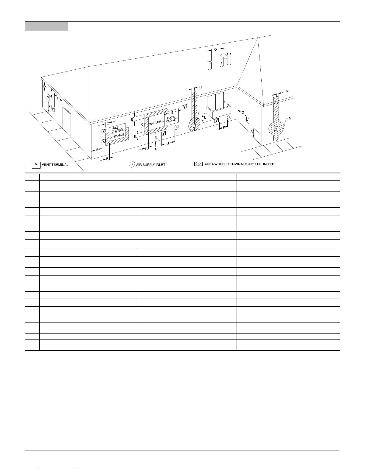
Figure 8 Direct Vent Termination Clearance
V
V
Item Clearance Description Canadian Installation (1)
A Clearance above grade, veranda, porch, deck, balcony, or
anticipated snow level
B Clearance to a window or door that may be opened 12″ (30 cm) for appliances u 10,000 Btuh (3 kW) and v
C Clearance to a permanently closed window
D Vertical clearance to a ventilated soffit located above the
terminal within a horizontal distance of 2′ (61cm) from the
centerline of the terminal
E Clearance to an unventilated soffit
F Clearance to an outside corner
G Clearance to an inside corner
H Clearance to each side of the centerline extended above
electrical meter or gas service regulator assembly
I Clearance to service regulator vent outlet 3′ (91 cm)
J Clearance to non-mechanical air supply inlet to building or
the combustion air inlet to any other appliance
K Clearance to a mechanical air supply inlet 6′ (1.83 m) 3′ (91 cm) above if within 10′ (3m) horizontally
L Clearance under a veranda, porch, deck, or balcony 12″ (30 cm) +
M Clearance to each side of the centerline extended above or
below vent terminal of the furnace to a dryer or water heater
vent, or other appliance's direct vent intake or exhaust.
N Clearance to the vent terminal of a dryer vent, water heater
vent, or other appliances direct vent intake or exhaust.
O Clearance from a plumbing vent stack 3′ (91 cm) 3′ (91 cm)
P Clearance above a paved sidewalk or paved driveway lo
cated on public property.
u greater than, w greater than or equal to, t less than, v less than or equal to
(1.) In accordance with the current CSA B149.1, Natural Gas and Propane Installation Code
(2.) In accordance with the current ANSI Z223.1/NFPA 54, National Fuel Gas Code
# 18″ (46 cm) above roof surface
+ Permitted only if veranda, porch, deck, or balcony is fully open on a minimum of two sides beneath the floor.
* For clearances not specified in ANSI Z223.1/NFPA 54 or CSA B149.1, clearances shall be in accordance with local installation codes and
the requirements of the gas supplier and the manufacture's installation instructions.
** A vent shall not terminate directly above a sidewalk or paved driveway that is located between two single family dwellings and serves both dwellings.
Notes:
1. The vent for this appliance shall not terminate
a. Over public walkways; or
b. Near soffit vents or crawl space vents or other areas where condensate or vapor could create a nuisance or hazard or property damage; or
c. Where condensate vapor could cause damage or could be detrimental to the operation of regulators, relief valves, or other equipment.
2. When locating vent terminations, consideration must be given to prevailing winds, location, and other conditions which may cause recirculation of the combustion products of adjacent vents.
Recirculation can cause poor combustion, inlet condensate problems, and accelerated corrosion of the heat exchangers.
3. Avoid venting under a deck or large overhang. Recirculation could occur and cause performance or system problems.
12″ (30cm) # 12″ (30 cm)
100,000 Btuh (30 kW), 36″ (91 cm) for appliances u 100,000
Btuh (30 kW)
9″ (23 cm) for appliances u 10,000 Btuh (3 kW) and v 50,000
Btuh (14.7 kW), 12″ (30 cm) for appliances u 50,000 Btuh (14.7
kW)
* *
* *
* *
* *
* *
3′ (91 cm) within 15′ (4.5 m) above the meter/regulator
assembly
*
*
12″ (30 cm) for appliances u 10,000 Btuh (3 kW) and v
100,000 Btuh (30 kW), 36″ (91 cm) for appliances u
100,000 Btuh (30 kW)
9″ (23 cm) for appliances u 10,000 Btuh (3 kW) and v
50,000 Btuh (15 kW), 12″ (30 cm) for appliances u 50,000
Btuh (14.7 kW)
*
12″ (30 cm) 12″ (30 cm)
3′ (91 cm) 3′ (91 cm)
7′ (2.13 m) **
*
U.S. Installation (2)
16
440 01 1024 04
Specifications are subject to change without notice
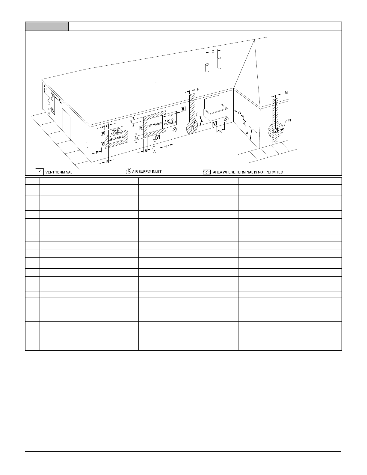
Figure 9 Other than Direct Vent Termination Clearance
V
V
Item Clearance Descriptions Canadian Installation (1)
A Clearance above grade, veranda, porch, deck, balcony, or
anticipated snow level
B Clearance to a window or door that may be opened 12″ (30 cm) for appliances u 10,000 Btuh (3 kW) and v
C Clearance to a permanently closed window
D Vertical clearance to a ventilated soffit located above the
terminal within a horizontal distance of 2′ (61cm) from the
centerline of the terminal
E Clearance to an unventilated soffit
F Clearance to an outside corner
G Clearance to an inside corner
H Clearance to each side of the centerline extended above
electrical meter or gas service regulator assembly
I Clearance to service regulator vent outlet 3′ (91 cm)
J Clearance to non-mechanical air supply inlet to building or
the combustion air inlet to any other appliance
K Clearance to a mechanical air supply inlet 6′ (1.83 m) 3′ (91 cm) above if within 10′ (3m) horizontally
L Clearance under a veranda, porch, deck, or balcony 12″ (30 cm)+
M Clearance to each side of the centerline extended above or
below vent terminal of the furnace to a dryer or water heater
vent, or other appliance's direct vent intake or exhaust.
N Clearance to the vent terminal of a dryer vent, water heater
vent, or other appliances direct vent intake or exhaust.
O Clearance from a plumbing vent stack
P Clearance above a paved sidewalk or paved driveway lo
cated on public property.
u greater than, w greater than or equal to, t less than, v less than or equal to
(1.) In accordance with the current CSA B149.1, Natural Gas and Propane Installation Code
(2.) In accordance with the current ANSI Z223.1/NFPA 54, National Fuel Gas Code
# 18″ (46 cm) above roof surface
+ Permitted only if veranda, porch, deck, or balcony is fully open on a minimum of two sides beneath the floor.
* For clearances not specified in ANSI Z223.1/NFPA 54 or CSA B149.1, clearances shall be in accordance with local installation codes and the requirements of the gas supplier and the manufacture's installation
instructions.
** A vent shall not terminate directly above a sidewalk or paved driveway that is located between two single family dwellings and serves both dwellings.
Notes:
1. The vent for this appliance shall not terminate
a. Over public walkways; or
b. Near soffit vents or crawl space vents or other areas where condensate or vapor could create a nuisance or hazard or property damage; or
c. Where condensate vapor could cause damage or could be detrimental to the operation of regulators, relief valves, or other equipment.
2. When locating vent terminations, consideration must be given to prevailing winds, location, and other conditions which may cause recirculation of the combustion products of adjacent vents.
Recirculation can cause poor combustion, inlet condensate problems, and accelerated corrosion of the heat exchangers.
3. Avoid venting under a deck or large overhang. Recirculation could occur and cause performance or system problems.
12″ (30cm) # 12″ (30 cm)
100,000 Btuh (30 kW), 36″ (91 cm) for appliances u 100,000
Btuh (30 kW)
4′ (1.2 m) below or to the side of the opening. 1′ (30 cm) above
the opening.
* *
* *
* *
* *
* *
3′ (91 cm) within 15′ (4.5 m) above the meter/regulator
assembly
3′ (91 cm) within 15′ (4.5 m) above the meter/regulator
assembly
*
12″ (30 cm) for appliances u 10,000 Btuh (3 kW) and v
100,000 Btuh (30 kW), 36″ (91 cm) for appliances u
100,000 Btuh (30 kW)
4′ (1.2 m) below or to the side of opening: 1′ (30 cm) above
opening.
*
* *
* *
* *
7′ (2.13 m) **
7′ (2.13 m)
U.S. Installation (2)
440 01 1024 04
17
Specifications are subject to change without notice
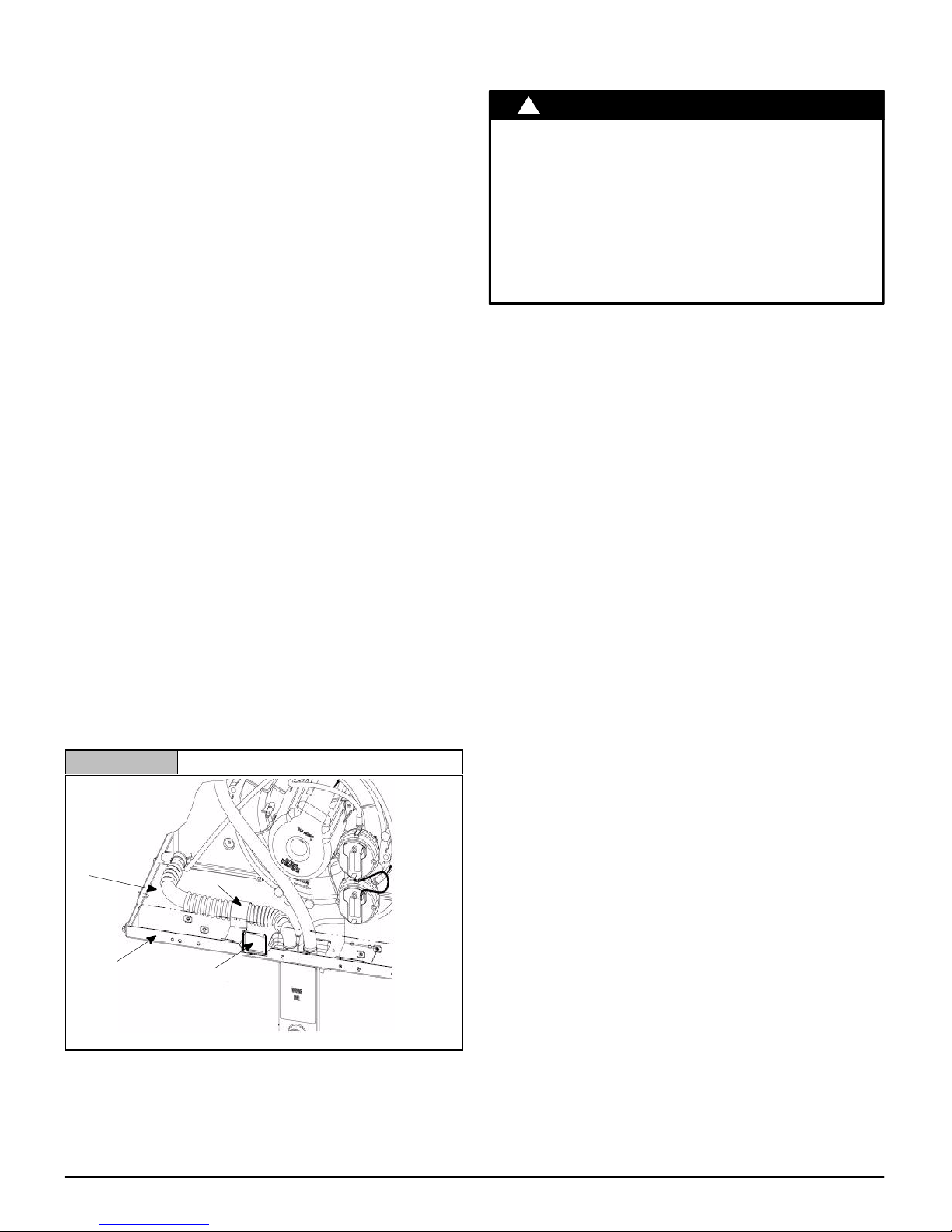
Condensate Drain Trap
This furnace removes both sensible and latent heat from the
products of combustion. Removal of the latent heat results in
condensation of the water vapor. The condensate is removed from
the furnace through the drains in the plastic transition and the vent
fitting. The drains connect to the externally mounted condensate
drain trap on the left or right side of the furnace.
The startup of a new furnace will involve a cycle or two of the
furnace to properly prime the condensate trap with water. Until the
trap is fully primed, some condensate will be pulled into the
combustion blower. The furnace may cycle on the pressure switch
connected to the plastic transition box due to condensate buildup.
After the trap is primed, the condensate will start draining from the
furnace. The combustion blower will clear out any remaining
condensate in the blower housing through the vent fitting
downstream of the blower. Note that the condensate trap can also
be primed by pouring water into the
Remove the1/2″ (12.7mm) ID drain hose from either the gutter or
the white PVC tee trap. Using a funnel pour eight (8) ounces (236
ml) of water into
through the drain hose and into the condensate drain trap. This will
prime both the vent and the transition sides of the trap. Reconnect
1
the
/2″ (12.7mm) ID drain hose to the original component, either
the gutter or the PVC tee trap.
The condensate drain trap supplied with the furnace MUST be
used. The drain connection on the condensate drain trap is sized
3
for
/4″ (19.1mm) PVC or CPVC pipe, however alternate 1/2″
(12.7mm) CPVC [nominal
a minimum inner diameter (I.D.) of 5/8″ (15.9mm) may also be
used, as allowed by local codes. Alternate drain pipes and hoses
may be used as allowed by local codes.
The drain line must maintain a
slope toward the drain.
Installation of an overflow line is recommended when the 1/4″
(6.4mm) per foot slope to the condensate drain cannot be
maintained. A drain tube retainer clip is included in the furnace to
prevent kinking/buckling of the drain tube. The retainer clip should
remain in the furnace (between the door switch plate and the
blower shelf, Figure 10) during operation. See Figure 20 for
proper routing and installation of the overflow.
1
/2″ (12.7mm) ID drain hose. Water will flow
5
/8″ (15.9mm) O.D.] or vinyl tubing with
1
/4″ (6.4mm) per foot is recommended.
Figure 10 Drain Tube Retainer Clip Location
1
/2″ (12.7mm) drain hose.
1
/4″ (6.4mm) per foot downward
DO NOT trap the drain line in any other location than at the
condensate drain trap supplied with the furnace.
!
CAUTION
FROZEN AND BURST WATER PIPE HAZARD
Failure to follow this caution may result in property
damage.
If a condensate pump is installed, a plugged
condensate drain or a failed pump may cause the
furnace to shut down. Do not leave the home
unattended during freezing weather without turning
off water supply and draining water pipes or
otherwise protecting against the risk of frozen pipes.
If possible, DO NOT route the drain line where it may freeze. The
drain line must terminate at an inside drain to prevent freezing of
the condensate and possible property damage.
1. A condensate sump pump MUST be used if required by
local codes, or if no indoor floor drain is available. The
condensate pump must be approved for use with acidic
condensate.
2. A plugged condensate drain line or a failed condensate
pump will allow condensate to spill. If the furnace is installed
where a condensate spill could cause damage, it is
recommended that an auxiliary safety switch be installed to
prevent operation of the equipment in the event of pump
failure or plugged drain line. If used, an auxiliary safety
switch should be installed in the R circuit (low voltage)
ONLY.
3. If the auxiliary switch in the condensate pump is used, the
furnace may shut down due to a blocked condensate line or
failed pump. To prevent frozen water pipes see the “Frozen
Water Pipe Hazard” section in this manual.
Condensate Drain Trap Freeze Protection
Special precautions MUST be made if installing furnace in an area
which may drop below freezing. This can cause improper
operation or damage to the equipment. If the the furnace
environment has the potential of freezing, the drain trap and drain
line must be protected. Use 3 to 6 watt per foot at 115 volt, 40° F
(4°C) self−regulating shielded and waterproof heat tape. Wrap the
drain trap and drain line with the heat tape and secure with the ties.
Follow the heat tape manufacturer’s recommendations.
Drain
Tube
Blowe
r Shelf
Representative drawing only, some models may vary in appearance.
18
Clip
Door
Switch
440 01 1024 04
Specifications are subject to change without notice
 Loading...