

International comfort products DLFBB09K, DLFBB12K, DLFBB24K, DLFBB18K Owner's Manual
OWNERS MANUAL
R---410A Ductless Split System
High-Wall Heat Pump
MODELS:
SIZES: 09, 12, 18, 24K
NOTE: Read the entire instruction manual before starting the
DLFBB-Indoor
installation.
SAFETY
SYSTEM REQUIREMENTS ..........................
PARTS NAME . . . . . . . . . . . . . ...... .................
MODEL NUMBER REFERENCE
HOW TO USE THE REMOTE CONTROL TO OPERATE
THE UNIT
EMERGENCY OPERATION
CLEAN AND MAINTENANCE
MALFUNCTION ANALYSIS . . . ..... ..... . .............
CLEARANCES. . . . . . . . . . . . . . . . . .. . . . . .... ............
TOOLS FOR INSTALLATION
SELECTION OF INSTALLATION LOCATION . . . . . . .
REQUIREMENTS FOR ELECTRIC CONNECTION.............
INSTALLATION OF INDOOR UNIT . . . . . ..... .... .......
CHECK AFTER INSTALLATION . . . . . ..... .... .......
CONFIGURATION OF CONNECTION PIPE . . . . . ... .......
PIPE EXPANDING METHOD . . . . . ............... .......
TABLE OF CONTENTS
CONSIDERATIONS
......
.. . .................. . .....................
......... ................
... . .....................
....... . .....................
........ ................
......... .................
......
PAG E
2
2
3
4
5
10
11
13
17
18
18
19
20
25
26
28
NOTE TO EQUIPMENT OWNER:
Please read this Owner’s Information Manual carefully before installing and using this appliance
and keep this manual for future reference.
For your convenience, please record the model and serial numbers of your new equipment in the
spaces provided. This information, along with the installation data and dealer contact information
will be helpful should your system require maintenance or service.
UNIT INFORMATION
Model #
Serial #
INSTALLA TION INFORMATION
Date Installed
Specifications are subject to change without notice. 421 02 9240 00
DEALERSHIP CONTACT INFORMATION
Company Name:
Address:
Phone Number:
Technician Nam e :
SAFETY CONSIDERATIONS
421 02 9240 00
Installing, starting up, and servicing air--conditioning equipment
can be hazardous due to system pressures, electrical components,
and equipment location (roofs, elevated structures, etc.).
Only trained, qualified installers and service mechanics should
install, start--up, and service this equipment.
Untrained personnel can perform basic maintenance functions such
as cleaning coils. All other operations should be performed by
trained service personnel.
When working on the equipment, observe precautions in the
literature and on tags, stickers, and labels attached to the
equipment.
Follow all safety codes. Wear safety glasses and work gloves. Keep
quenching cloth and fire extinguisher nearby when brazing. Use
care in handling, rigging, and setting bulky equipment.
Read these instructions thoroughly and follow all warnings or
cautions included in literature and attached to the unit. Consult
local building codes and National Electrical Code (NEC) for
special requirements. Recognize safety information. This is the
!
safety--alert symbol
in instructions or manuals, be alert to the potential for personal
injury.Understand these signal words: DANGER, WARNING, and
CAUTION. These words are used with the safety--alert symbol.
DANGER identifies the most serious hazards which will result in
severe personal injury or death. WARNING signifies hazards
which could result in personal injury or death. CAUTION is used
to identify unsafe practices which may result in minor personal
injury or product and property damage. NOTE is used to highlight
suggestions which will result in enhanced installation, reliability, or
operation.
!
ELECTRICAL SHOCK HAZARD
Failure to follow this warning could result in personal
injury or death.
Before installing, modifying, or servicing system, main
electrical disconnect switch must be in the OFF
position. There may be more than 1 disconnect switch.
Lock out and tag switch with a suitable warning label.
!
. When you see this symbol on the unit and
WARNING
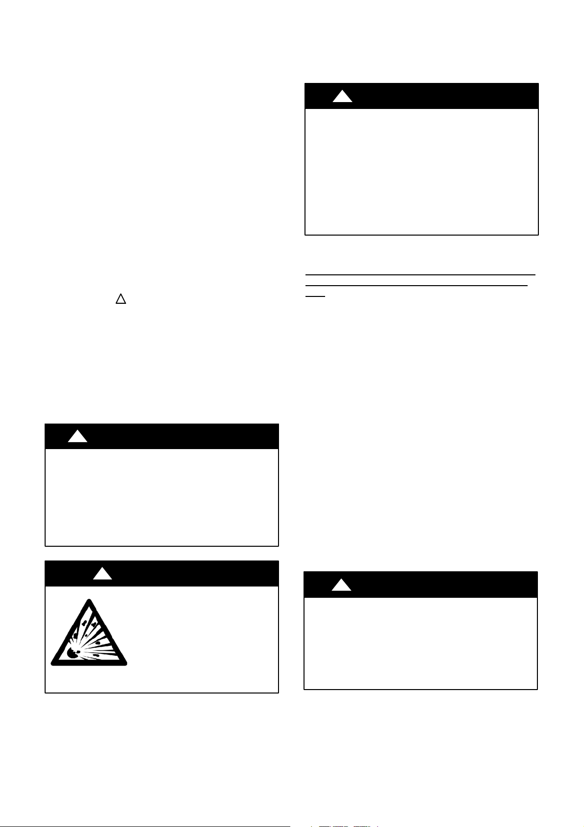
!
WARNING
EXPLOSION HAZARD
Failure to follow this warning could
result in death, serious personal injury,
and/or property damage.
Never use air or gases containing
oxygen for leak testing or operating
refrigerant compressors. Pressurized
mixtures of air or gases containing
oxygen can lead to an explosion.
!
EQUIPMENT DAMAGE HAZARD
Failure to follow this caution may result in equipment
damage or improper operation.
Do not bury more than 36 in. (914 mm) of refrigerant pipe
in the ground. If any section of pipe is buried, there must be
a 6 in. (152 mm) vertical rise to the valve connections on
the outdoor units. If more than the recommended length is
buried, refrigerant may migrate to the cooler buried section
during extended periods of system shutdown. This causes
refrigerant slugging and could possibly damage the
compressor at start--up.
CAUTION
SYSTEM REQUIREMENTS
Allow sufficient space for airflow and servicing unit.
Recommended Connection Method for Power and
cation Wiring (To minimize communication wiring
ence)
Power Wiring:
The main power is supplied to the outdoor unit. The field supplied
connecting cable from the outdoor unit to indoor unit consists of
three (3) wires and provides the power for the indoor unit. Two
wires are high voltage AC power and one is a ground wire.
Consult your local building codes and the NEC (National
Electrical Code) or CEC (Canadian Electrical Code) for special
requirements.
All wires must be sized per NEC or CEC and local codes. Use
Electrical Data table MCA (minimum circuit amps) and MOCP
(maximum over current protection) to correctly size the wires and
the disconnect fuse or breakers respectively.
Per caution note, only copper conductors with a minimum 300 volt
rating and 2/64--inch thick insulation must be used.
Communication Wiring:
A separate shielded copper conductor only, with a minimum 300
volt rating and 2/64--inch thick insulation, must be used as the
communication wire from the outdoor unit to the indoor unit.
To minimize voltage drop, the factory recommended wire size
is 14/3 stranded with a ground. In special cases where there is
high electrical interference, please use a separate shielded 16GA
stranded control wire.
When installing in an application where there is high electrical
frequency all wires should be shielded.
!
EQUIPMENT DAMAGE HAZARD
Failure to follow this caution may result in equipment
damage or improper operation.
S Wires should be sized based on NEC and local codes.
S Use copper conductors only with a minimum 300 volt
rating and 2/64 inch thick insulation.
CAUTION
Communi-
interfer-
2 Specifications are subject to change without notice.
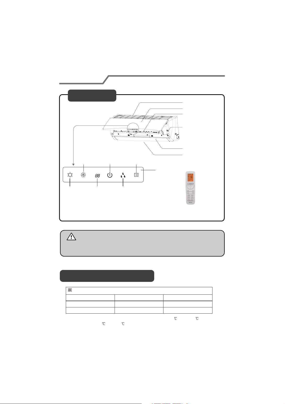
Parts Name
421 02 9240 00
Indoor Unit
cooling
indicator
power
indicator
receiver
window
air inlet
panel
filter
aux.button
horizontal louver
air outlet
display
F
heating
indicator
temp.
indicator
drying
indicator
remote controller
Notice:
Actual product may be different from above graphics, refer to actual
Working temperature range
Operating Temperature Range(Optional)
Indoor side DB/WB(
Maximum cooling
Maximum heating
The operating temperature range (outdoor temperature) cooling is -0.39 F
for heating is -4 F
o
(-20 )
~75 F
o
(24 ).
89.6/73.4(32/23)
80.6/-(27/-)
o
o
F/ C)
Outdoor side DB/WB(
o
(-18 )
118.4/-(48/-)
75.2/64.4(24/18)
o
(48 );
~118.4 F
products.
o
o
F/ C)
3Specifications are subject to change without notice.
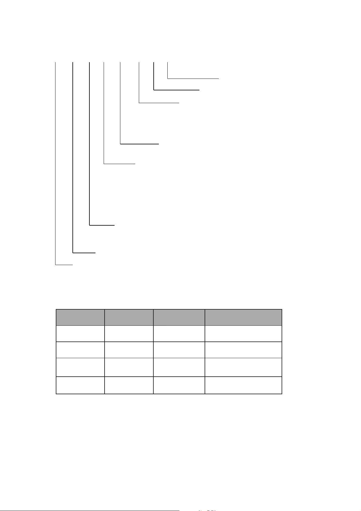
0RGHO 1XPEHU 5HIHUHQFH
DLF A H H 09 K 1 A
Position 7, 8 - System capacity in 1000 BTU/Hr
Example: 09 = 9000 BTU/Hr
Position 6 - Indoor Fan Coil Unit Type
B = High-Wall
C = Cassette
D=Ducted
F = Console
G = Underceiling
H = High Wall Color Variation
R=Outdoor
Position 11 - Not Defined
Position 10 – Not Defined
Position 9 - Electrical characteristics
J = 115/l/60
K = 208-230/l/60
H = 208-230/3/60
L = 460/3/60
Position 5 – Unit Type
A = Cooling Only
H = Heat Pump
Position 4 - Model letter
Positions 1 to 3 - Equipment type
DLF = Indoor unit;
DLC = Outdoor unit
System Tons Unit Btuh Volt-Ph@60Hz Indoor Model Number
0.75 9000 208/230-1 DLFBHB09K1A
1.00 12000 208/230-1 DLFBHB12K1A
1.50 18000 208/230-1 DLFBHB18K1A
2.00 24000 208/230-1 DLFBHB18K1A
4 Specifications are subject to change without notice. 421 02 9240 00
How to use the remote control to operate the unit
e
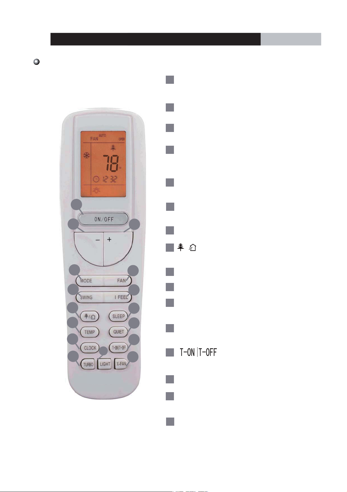
Remote Controller Description
1
ON/OFF
Press to start or stop operation.
2
: Press to decrease temperature
-
setting.
3
+
: Press to increase temperature
setting.
4
MODE
Press to select the operation mode
F
(AUTO/COOL/DRY/FAN/HEAT).
5
FAN
Press to set the fan speed.
OPERATION INSTRUCTIONS
2
4
6
8
10
12
14
1
6
SWING
Press to set the swing angle.
3
7
I FEEL
8
(This function is only applicable for certain models.)
/
Press to set the HEALTH or AIR function.
5
7
9
9
SLEEP
10
TEMP
11
QUIET
Press to set
the QUIET function.
11
12
CLOCK
13
15
Press to set the clock.
13
16
Press to set the auto-off /auto-on timer.
421 02 9240 00
14
TURBO
15
LIGHT
Press to turn on/off the light.
16
X-FAN
5Specifications are subject to change without notic
How to use the remote control to operate the unit
e
OPERATION INSTRUCTIONS
Remote Controller Description
1
ON/OFF :
Press this button to turn on the unit .Press this button again to turn off the unit.
2
Press this button to decrease the set temperature. Hold it down for more than 2 seconds
to rapidly decrease the set temperature. In the AUTO mode, the set temperature is not adjustable.
+ :
3
Press this button to increase the set temperature.Hold it down for more than 2 seconds
to rapidly increase the set temperature. In the AUTO mode, the set temperature is not adjustable.
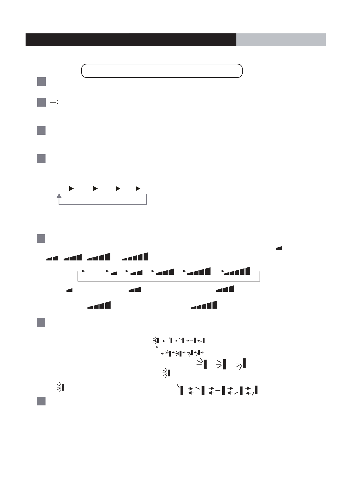
4
MODE :
Each time you press this button, a mode is selected in a sequence that goes from AUTO,
COOL,DRY, FAN,and HEAT
AUTO
COO L
DRY
*
FAN HEAT
*
*Note: Only for models with the heating function.
After powering on the unit defaults to the , AUTO mode. In the AUTO mode, the set temperature does not
be display on the LED of the indoor, and the unit automatically selects the suitable operation
mode in accordance with the room temperature to make indoor room comfortable.
5
:
FAN
This button is used for setting the fan speed in the sequence that goes from AUTO,
,,
Aut o
to
,
then back to Auto.
,
Medium speedLow-Medium speedLow speed
High speedMedium-High speed
6
SWING:
Press this button to set the up and down swing angle, which changes as shown in the image below
OFF
:
This remote controller is universal . If any command , or is transmitted ,
the unit carries out the command as
indicates the guide louver swings as:
I FEEL:
7
Press this button to turn on the I FEEL function. The unit automatically adjusts the temperature
according to the sensed temperature. Press this button again to cancel I FEEL function.
6 Specifications are subject to change without notic
421 02 9240 00
How to use the remote control to operate the unit
8
/
P
ress this button to activate the on and off healthy and scavenging functions in the operation status.
Press this button one time to start the scavenging function;
the LCD displays the“ ”icon. Press the button a
simultaneously; the LCD displays“ ” and the“ ” icons .
healthy and scavenging functions simultaneously. Press the button a fourth time to start the healthy
function; the LCD displays the“ ”
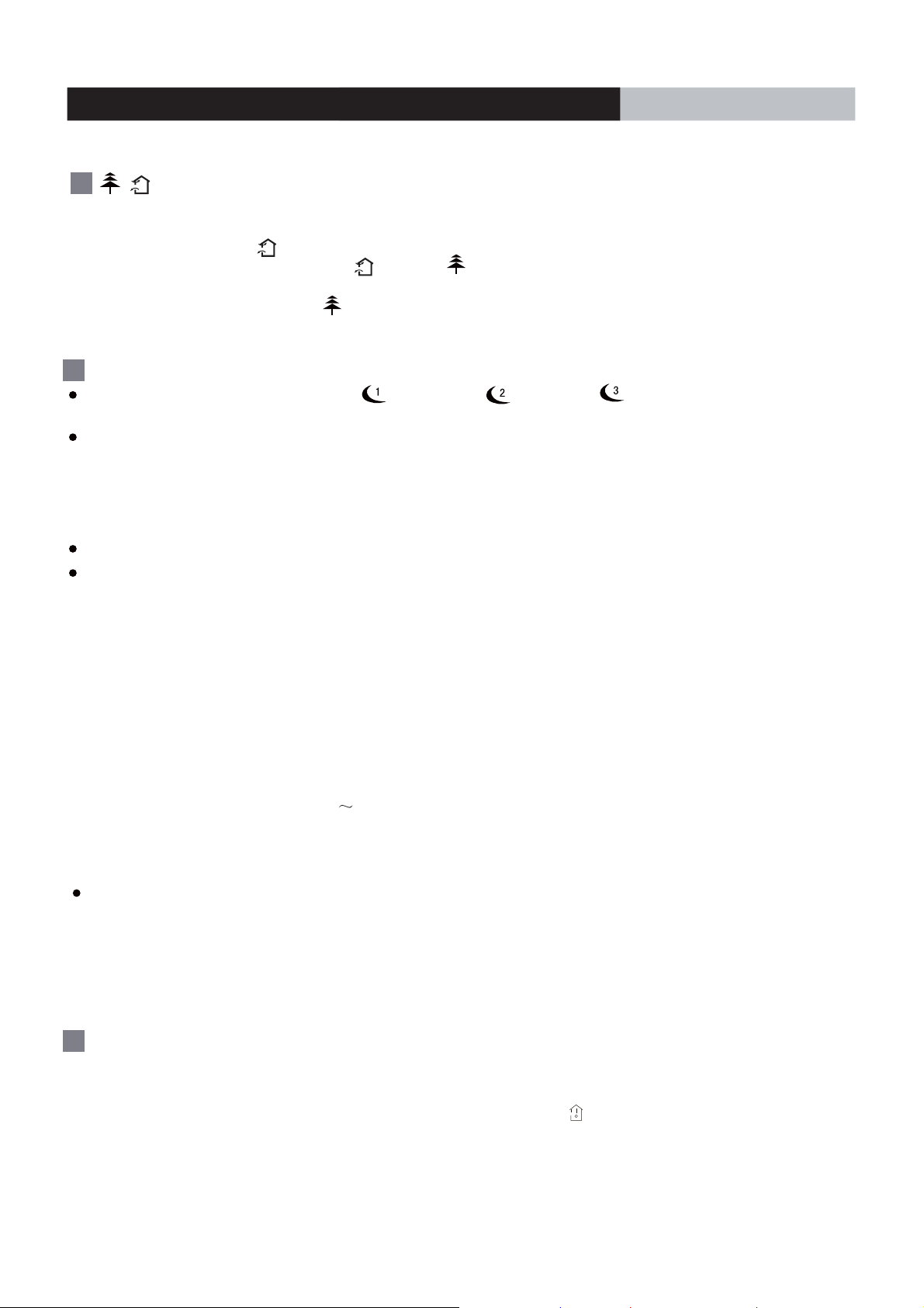
SLEEP:
9
Press this button to select Sleep 1 ( ), Sleep 2 ( ),Sleep 3 ( ) .to cancel Sleep,
circulate between the Sleep modes., Once the unit is powered on, Sleep Cancel mode Cancel is the default.
Sleep 1 - Sleep mode 1: in the Cool, and Dehumidify modes: sleep status after the unit runs for one hour, the main
unit setting temperature increases1.8 ℉ (1 ℃)
setting temperature. In Heat mode: sleep status after the unit runs for one hour, the setting temperature
decreases 1.8 ℉ (1 ℃)
temperature.
Sleep 2 - sleep mode 2:the air conditioner runs according to the group preset of the sleep temperature curve.
Sleep 3: the sleep curve setting under the Sleep mode by DIY:
(1) Under Sleep 3 mode, press the"Turbo" button for a long time, the remote control enters the user
individual sleep setting status. The time of remote control displays"1 hour ", the setting temperature "88"
displays the corresponding temperature of the last setting sleep curve and blinks (The first settde displays
according to the initial curve setting value of the factory).
(2) Adjust the"+" and "-" button, to change the corresponding setting temperature. After adjusting, press the
"Turbo"button for conf irmation.
(3) At this time, 1 hour is automatically increased at the timer postion on the remote control, (the increments are
"2 hours " or "3 hours " or "8 hours "), the location of the setting temperature "88" displays the
corresponding temperature of the last setting sleep curve and blinks.
(4) Repeat the previous steps (2)
curve setting the finished.The remote control resumes the original timer displays.
temperature display resumes the original setting temperature.
Sleep3: the sleep curve setting under the SLEEP mode by DIY could be located.
The user could use the sleep curve setting method to find the presetting sleep curve, enter into the the user
individual sleep setting status, however can not change the temperature. Press the"Turbo" button for confirmation.
Note: In the above presetting or inquiry procedure, if after 10 seconds, there is no button pressed, the sleep
curve setting status will stop automatically and resume the original displaying. In the presetting or inquiry
procedure, press the "ON/OFF"button, "Mode" button, "Timer"button or "Sleep" button, and the sleep curve
setting or inquiry status will stop.
. After 2 hours, the setting temperature decreases 3.6 ℉ (2℃)
icon. Press the button again to repeat the operation above.
,the setting temperature increaseds 3.6 ℉ (2℃) . The unit runs at this
(3) until the 8 hours temperature setting is finished and the sleep
second time to start the healthy and scavenging functions
Press the button a third time to deactivate the
OPERATION INSTRUCTIONS
, then the unit runs at this setting
10
TEMP:
Press this button, to display the indoor setting temperature or indoor ambient
temperature. When the indoor unit powers on , it displays the setting temperature.
If the temperature's display status changes from another status to" ",the
ambient temperature appears, and within 5s, if it receives another remote control signal it will
return the display to the setting temperature. If the users have not configured the temperature
displaying status,it will display the setting temperature.
7Specifications are subject to change without notice. 421 02 9240 00

How to use the remote control to operate the unit
e
QUIET:
11
Press this button, the Quiet status is under the Auto Quiet mode (display and "Auto"" " signal)
along with the Quiet (display " " signal and the Quiet OFF modes (the signal " " does not display),
and after powering on, the Quiet OFF is the default. Note: the Quiet function cannot be set in the Fan
and Dry mode. Under the Quiet mode (Display " " signal), the fan speed is not available.
12
CLOCK :
Press the CLOCK button . Within 5 seconds, press the +or - button to adjust the
current time. Holding down either button for more than 2 seconds to increase or decrease the
time by 1 minute every 0.5 second and then by 10 minutes every 0.5 second. While
blinking after the setting, press the CLOCK button again to confirm the setting,and the
icon will
13
T-ON T-OFF:
Press the T-ON button to initiate the auto-ON timer. To cancel the auto-timer program,
press the button again.
setting). Within 5 seconds, press the + or - button to adjust the time value. Every press of either
buttonchanges the time setting by 1 minute. Hold down either button rapidly to change the
time settingby 1 minuteand then 10minutes. Within 5 Seconds aftersetting, press the TIMER
ON button to confirm.
Press the T-OFF button to initiate the auto-off timer. To cancel the auto-timer program,
press the button again.The TIMER OFF setting is the same as TIMER ON.
constantly appear .
(0. sknilb" NO" dna sraeppasiicon d , thenottubehtpressingretfA
0:00 displays for the ON time
OPERATION INSTRUCTIONS
TURBO:
14
Press this button to activate or deactivate the Turbo function which enables the unit to
reach the preset temperature in the shortest time. Inthe COOL mode, the unit blows strong
cooling air at a super high fan speed. In HEAT mode, the unit blows strong heating air
at a super high fan speed.
15
LIGHT:
Press the LIGHT button to turn on the display's light and press this button again to turn off
the display's light. If the light is turned on , the icon displays. If the light is turned off the ,
icon disappears.
X-FAN:
16
Pressing the X-FAN button in the COOL or DRY mode,the icon displays and the indoor
fan continues to operate for 10 minutes to dry the indoor unit even though
the unit is turned off.
After powering on , the X-FAN OFF is the default. the X-FAN is not available in the AUTO,FAN or
HEAT mode.
Combination of the "+" and "-" buttons: About lock
17
Press the"+"and "-" buttons simultaneously
controller is locked, the icon
displays. In this case,
to lock or unlock the keypad. If the remote
press any button and the icon blinks
three times.
8 Specifications are subject to change without notic
421 02 9240 00
How to use the remote control to operate the unit
e
OPERATION INSTRUCTIONS
Combination of "the MODE " and "-" buttons:
18
In the OFF mode, press " the MODE"
Combination of " the TEMP " and "CLOCK" buttons : Engages the Energy-saving function
19
and - " " buttons simultaneously to switch between and .
Switches between Fahrenheit and centigrade
Press “the TEMP” and “CLOCK” simultaneously in the COOL mode to start THE Energy-saving
function.
Combination of " TEMP " and "CLOCK" buttons : About Heating function
20
Press “TEMP” and “CLOCK” simultaneously in the HEAT mode to start
Nixie tube on the remote controller displays “SE”. Repeat the operation to quit the function.
46 ℉ (8 ℃)
the 46
℉ (8 ℃)
Heating function.The Nixie tube on the remote controller displays the “ ” logo and a selected
46 temperature of “ ℉ (8 ℃) ”
21
About Back-lighting function
Repeat the operation to exit the function.
.
The unit lights for 4s whenpowering on the first time, and 3s for each subsequent press.
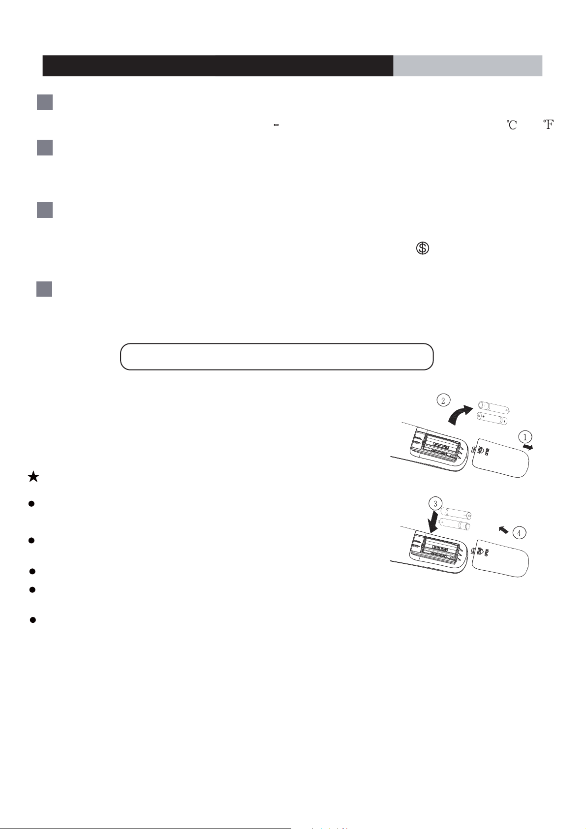
Replacement of Batteries
1.Remove the battery cover plate from the rear of the remote controller.
(As shown in the figure)
2.Remove the old batteries.
3.Insert two new AAA1.5V dry batteries, and pay attention to the polarity.
4. Reinstall the battery cover plate.
Notes:
When replacing the batteries, do not use old or different types of batteries,
otherwise, it may cause malfunction.
If the remote controller will not be used for a long time,
remove batteries to prevent batteries from leaking.
The operation should be performed in within the unit's receiving range.
The remote controller It should be kept 3.28ft (1 m) away from the TV set or
stereo sound sets.
If the remote controller does not operate normally, take the
batteries out and reinsert them after 30 seconds. If it still does not operate properly,
replace the batteries.
Sketch map for
replacing batteries
421 02 9240 00
9Specifications are subject to change without notic
 Loading...