

International comfort products DLC4A, DLC4H, DLF4A, DLF4H Owner's Manual

OWNER’S MANUAL
R−410A Ductless Split System
Air Conditioner and Heat Pump
Models: DLC4(A/H)−Outdoor Unit, DLF4(A/H)−Indoor Unit
Sizes: 9K, 12K, 18K, 24K, 30K and 36K
Please read the operating instructions and safety precautions carefully and thoroughly before installing and
operating your room air conditioner or heat pump.
TABLE OF CONTENTS
PAGE
SAFETY PRECAUTIONS 2...................................................................................
GENERAL 2................................................................................................
INDOOR / OUTDOOR UNIT PART NAMES 3...................................................................
REMOTE CONTROL AND FUNCTIONS 4−13...................................................................
CLEANING, MAINTENANCE AND TROUBLESHOOTING 14−15...................................................
NOTE TO EQUIPMENT OWNER:
Thank you for your purchase. Please read this Owner’s Information Manual carefully
before installing and using this appliance and keep this manual for future reference.
For your convenience, please record the model and serial numbers of your new
equipment in the spaces provided. This information, along with the installation data and
dealer contact information, will be helpful should your system require maintenance or
service.
UNIT INFORMATION
Model # _________________________________
Serial # _________________________________
INSTALLATION INFORMATION
Date Installed ____________________________
DEALERSHIP CONTACT INFORMATION
Company Name: ______________________________
Address:_____________________________________
____________________________________________
Phone Number:______________________________
Technician Name:_____________________________
421 02 9218 00 10/01/12
OWNER’S MANUAL Ductless Split System − DLC4(A/H), DLF4(A/H)
SAFETY PRECAUTIONS
NOTE is used to highlight suggestions which will result in
!
WARNING
PERSONAL INJURY, DEATH, OR PROPERTY
DAMAGE HAZARD
Failure to follow this warning could result in personal
injury, death, or property damage.
Read and follow all instructions and warnings, including
labels shipped with or attached to unit before operating
your new air conditioner.
Any time you see this symbol in manuals, instructions
and on the unit, be aware of the potential for personal injury.
There are three levels of precaution:
DANGER identifies the most serious hazards which will
result in severe personal injury or death.
WARNING signifies hazards that could result in personal
injury or death.
CAUTION is used to identify unsafe practices which would
result in minor personal injury or product and property
damage.
enhanced installation, reliability, or operation.
!
PERSONAL INJURY, DEATH AND / OR PROPERTY
DAMAGE HAZARD
Failure to follow this warning could result in personal
injury, death or property damage.
Improper installation, adjustment, alteration, service,
maintenance, or use can cause explosion, fire,
electrical shock, or other conditions which may cause
personal injury or property damage.
Consult a qualified installer, service agency, your
distributor or branch for information or assistance. The
qualified installer or service agency must use
factory−authorized kits or accessories when modifying
this product.
WARNING
GENERAL
The high wall fan coil unit provides quiet, maximum comfort.
In addition to cooling and/or heating, the high wall fan coil
unit matched with an outdoor condensing unit will filter and
dehumidify the air in the room to provide maximum comfort.
IMPORTANT: The high wall fan coil unit should be installed
by authorized personnel only; using approved tubing and
accessories. If technical assistance, service or repair is
needed, contact the installer or local dealer or call
1−877−591−8908.
The high wall fan coil unit can be set up and operated from
the remote control (provided). If the remote is misplaced,
the system can be operated from the “Auto” setting on
the unit.
Operating Modes:
The high wall fan coil unit has five operating modes.
S Auto
S Cooling
S Dehumidification (DRY)
S Fan Only
S Heating (heat pump models only)
Fan Only
In Fan Only mode, the system filters and circulates room air
without changing room air temperature.
Auto
In Auto mode, the system will automatically cool or heat the
room according to the factory setting in Auto Mode. The
setpoint temperature is not adjustable.
Heating
In Heating mode, the system heats and filters room air.
Cooling
In Cooling mode, the system cools, dries and filters room air.
Dehumidification (DRY)
In Dehumidification mode, the system dries, filters and
slightly cools room air temperature. This mode does not
take the place of a dehumidifier.
Remote Control
The remote control transmits commands to set up and
operate the system. The controller has a window display
panel that shows the current system status. The controller
can be secured to a surface when used with the provided
mounted remote control holder.
2 421 02 9218 00
OWNER’S MANUAL Ductless Split System − DLC4(A/H), DLF4(A/H)
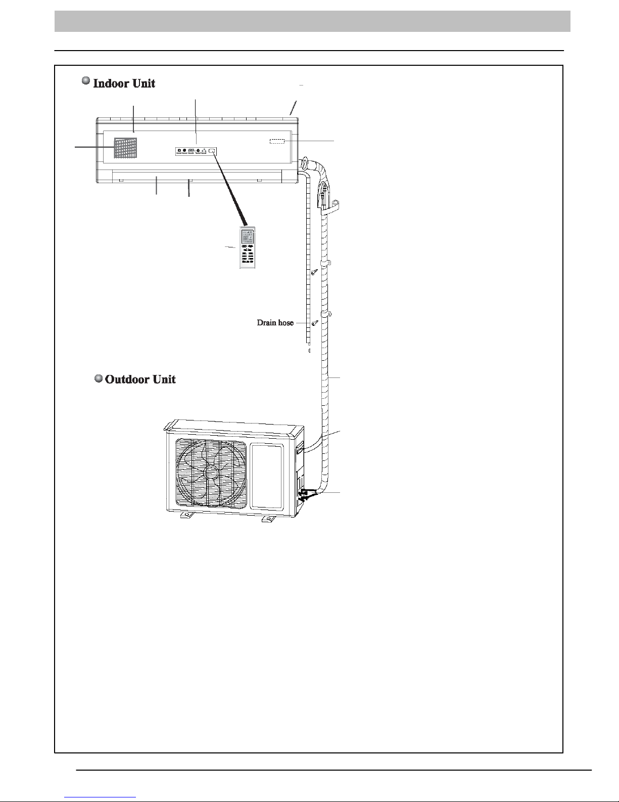
Indoor / Outdoor Units
3
4
5
2
6
7
1
8
1. Front Panel Frame
2. Display Panel
3. Front Panel
4. Air Filter
5. Horizontal Airflow Louver
6. Manual Adjustable Vertical Airflow Louver
7. Remote Control
8. Room Temperature Sensor
9. Inter-Connecting Tubing
10. Control and Power Wiring to Indoor Unit
11. Service Valves
9
10
11
Size 09-36, Indoor/Outdoor Unit
A08294a
421 02 9218 00 3
OWNER’S MANUAL Ductless Split System − DLC4(A/H), DLF4(A/H)
Remote Control and Functions
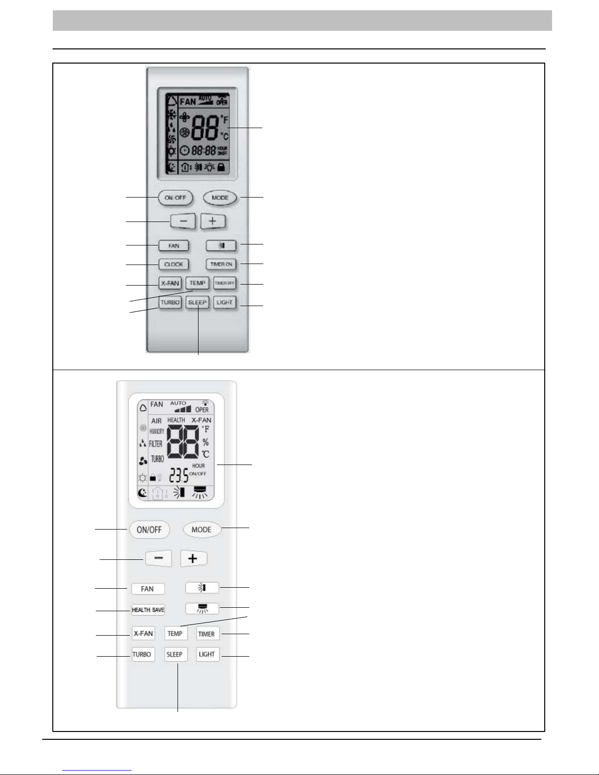
Remote Control, Size 09-24
1. Remote Control Display
2. ON/OFF Button
1
3. MODE Button
4. Setpoint Clock, Timer Up (+) and Down (-) Buttons
5. Fan Speed
6. Horizontal Louver Swing Button
7. Clock Button
23
4
5
7
9
10
12
8. Timer ON Button
9. Dry Coil Button
10. Temperature Button
11. Timer OFF Button
6
12. Turbo Mode Button
8
13. Sleep Mode button
14. Light Button to Turn ON or OFF Display on Front Panel
11
14
13
1. Remote Control Display
2. ON/OFF Button
3. MODE Button
1
4. Setpoint, Timer Up (+) and Down (-) Buttons
5. Fan Speed
6. Horizontal Louver Swing Button
7. Left/Right Louver Swing Button (Not available with these models)
8. HEALTH/SAVE Button (Not available with these models)
2
4
5
8
9
3
9. Dry Coil Button
10. Temperature Button (Not available with these models)
11. Timer Button
12. Turbo Mode Button (Not available with these models)
13. Sleep Mode button
6
14. Light Button to Turn ON or OFF Display on Front Panel
7
10
11
A12434
Remote Control, Size 30-36
12
13
4 421 02 9218 00
14
A12390
OWNER’S MANUAL Ductless Split System − DLC4(A/H), DLF4(A/H)
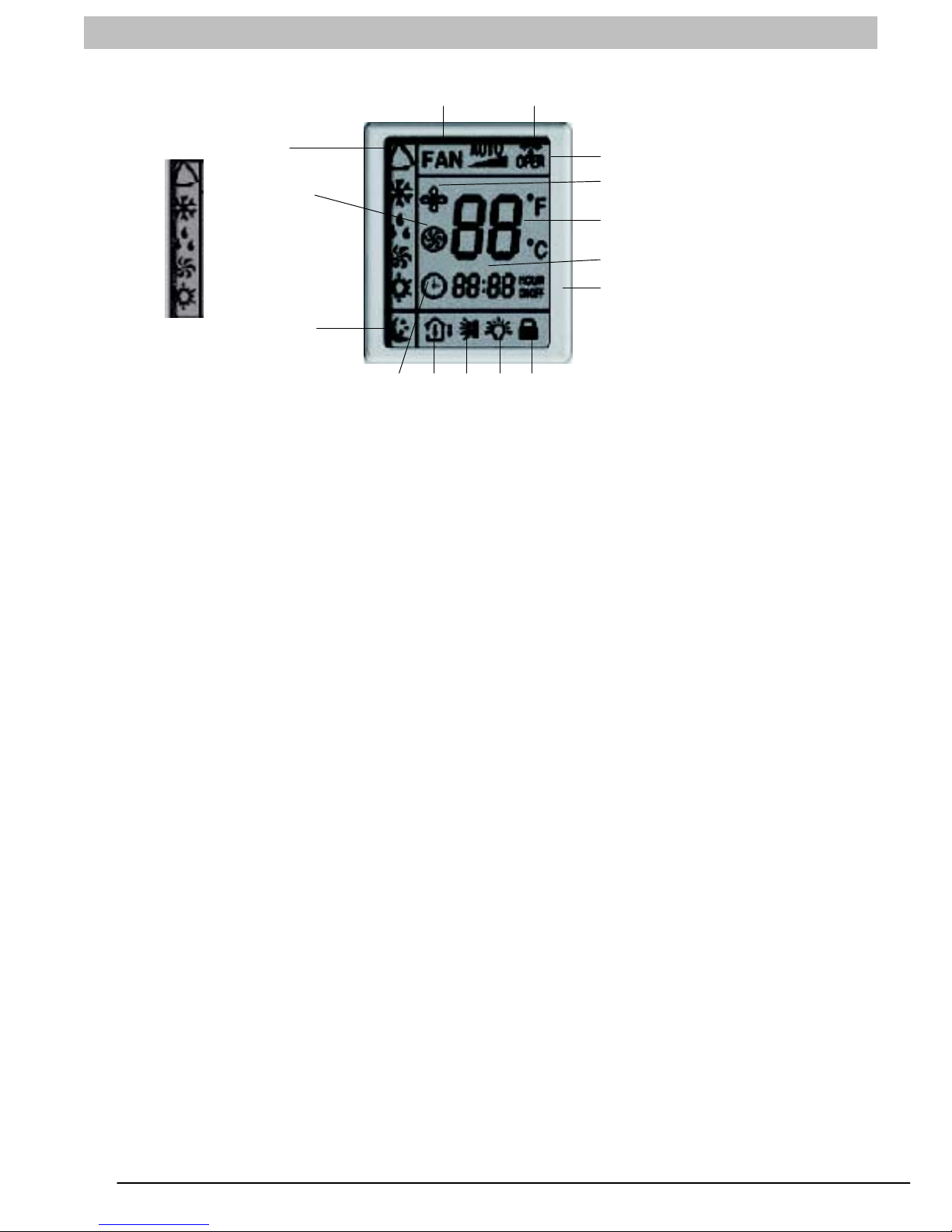
Remote Control Display, Size 09−24
3
MODE DISPLAY
AUTO
COOL
DRY
FAN
HEAT
NOTE: Symbols shown in this manual are for the purpose of demonstration. During actual operation, only the relevant
symbols are displayed.
1. TRANSMISSION INDICATOR: Illuminates when
remote control transmits signals to the indoor unit.
2. This symbol appears when the unit is turned on by
the remote control, and disappears when the unit is
turned off.
3. FAN SPEED DISPLAY: Indicates the set fan speed.
AUTO is displayed when unit is running in AUTO
mode.
4. MODE DISPLAY: Indicates the current operation
mode “AUTO”, “COOL”, “DRY”, “FAN ONLY”, or
“HEAT”
5. SLEEP DISPLAY: Indicates unit is running in SLEEP
mode.
6. TEMPERATURE DISPLAY: Temperature setting
from 61_F (16_C) to 86_F (30_C) will be displayed.
If FAN mode is selected, there will be no temperature
displayed.
7. CLOCK DISPLAY: Indicates the current time (0 to 24
hours).
8. CLOCK INDICATOR: Displayed with time and is not
displayed when setting ON/OFF timer.
4
10
5
1
2
11
6
7
9
A12391
151413128
9. TIMER ON / TIMER OFF DISPLAY: ON is displayed
if TIMER ON is set. OFF is displayed if TIMER OFF
is set. ON OFF displayed if both ON and OFF timers
are set.
10. TURBO DISPLAY: Indicates unit is running in Turbo
Mode.
11. DRY COIL DISPLAY: Indicates unit is running in DRY
COIL mode where the fan continues to run after the
unit is shut off to dry the coil.
12. TEMPERATURE DISPLAY: Indicates if room
temperature or set point temperature is being
displayed on the front panel.
13. SWING DISPLAY: Sets louver position or set louvers
to continuously move for better air distribution.
14. LIGHT DISPLAY: Indicates if LED display on the front
panel is illuminated.
15. LOCK DISPLAY: Indicates if remote control is locked.
421 02 9218 00 5
 Loading...