

International comfort products DLFCAB, DLFCHB, DLCCAR, DLCCHR, DLCDAR Installation Instructions Manual
...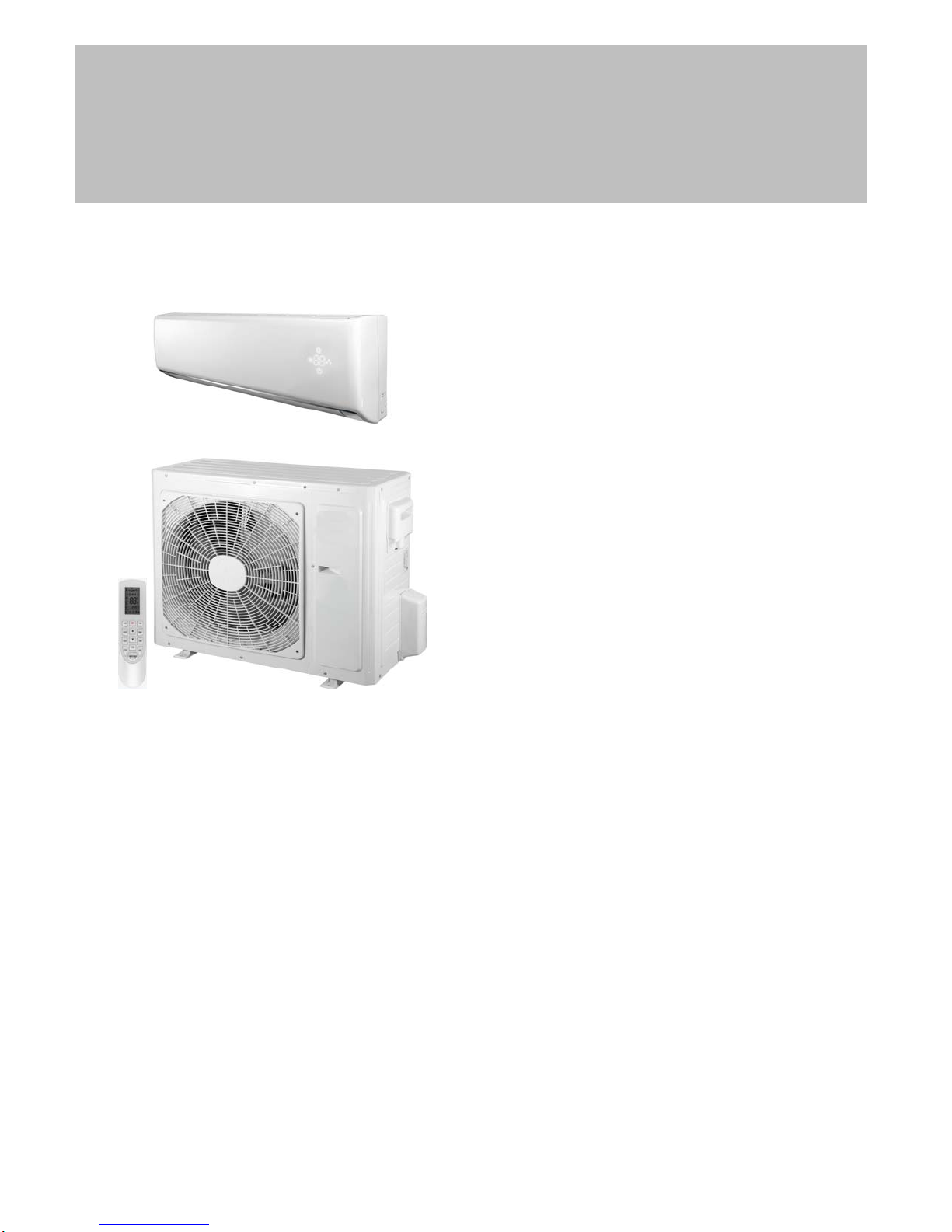
DLFCAB / DLCCAR / DLFCHB / DLCCHR
DLFDAB / DLCDAR / DLFDHB / DLCDHR
INSTALLATION INSTRUCTIONS
High Wall Ductless Split System − Sizes 09 to 36
NOTE: Read the entire instruction manual before starting the installation.
TABLE OF CONTENTS
PAGE
SAFETY CONSIDERATIONS 2.............................
GENERAL 2.............................................
SYSTEM REQUIREMENTS 2...............................
Piping 2.............................................
PIPING AND REFRIGERANT TABLES DLFCAB / DLCCAR /
DLFCHB / DLCCHR 3.....................................
PIPING AND REFRIGERANT TABLES DLFDAB / DLCDAR /
DLFDHB / DLCDHR 4....................................
DIMENSIONS−INDOOR 6.................................
DIMENSIONS−OUTDOOR 7...............................
CLEARANCES−INDOOR 8................................
CLEARANCES−OUTDOOR 8..............................
INSTALLATION GUIDE 9..................................
INDOOR UNIT INSTALLATION 9...........................
Install Mounting Plate 9.................................
Drill Hole in Wall for Interconnecting Piping, Drain
and Wiring 9.........................................
OUTDOOR UNIT INSTALLATION 9.........................
Piping Connections to Outdoor Unit 9.....................
INSTALL ALL POWER, INTERCONNECTING WIRING AND
PIPING TO INDOOR UNIT 11..............................
SYSTEM VACUUM AND CHARGE 11.......................
START−UP 13............................................
WIRING DIAGRAMS 14...................................
TROUBLESHOOTING 15..................................
The following parts are included in your indoor unit. Please contact
your dealer if any parts are damaged or missing.
Table 1—Parts List
Mounting Plate 1
Mounting Hardware 7
Remote Control 1
Remote Control Holder 1
Battery (1.5V) 2
Parts Qty
Specifications subject to change without notice.
SAFETY CONSIDERATIONS
Installing, starting up, and servicing air−conditioning equipment can be
hazardous due to system pressures, electrical components, and
equipment location (roofs, elevated structures, etc.).
Only trained, qualified installers and service mechanics should install,
start−up, and service this equipment.
Untrained personnel can perform basic maintenance functions such as
cleaning coils. All other operations should be performed by trained
service personnel.
When working on the equipment, observe precautions in the literature
and on tags, stickers, and labels attached to the equipment.
Follow all safety codes. Wear safety glasses and work gloves. Keep
quenching cloth and fire extinguisher nearby when brazing. Use care in
handling, rigging, and setting bulky equipment.
Read these instructions thoroughly and follow all warnings or cautions
included in literature and attached to the unit. Consult local building
codes and current editions of the National Electrical Code (NEC) NFPA
70. In Canada, refer to current editions of the Canadian electrical code
CSA 22.1.
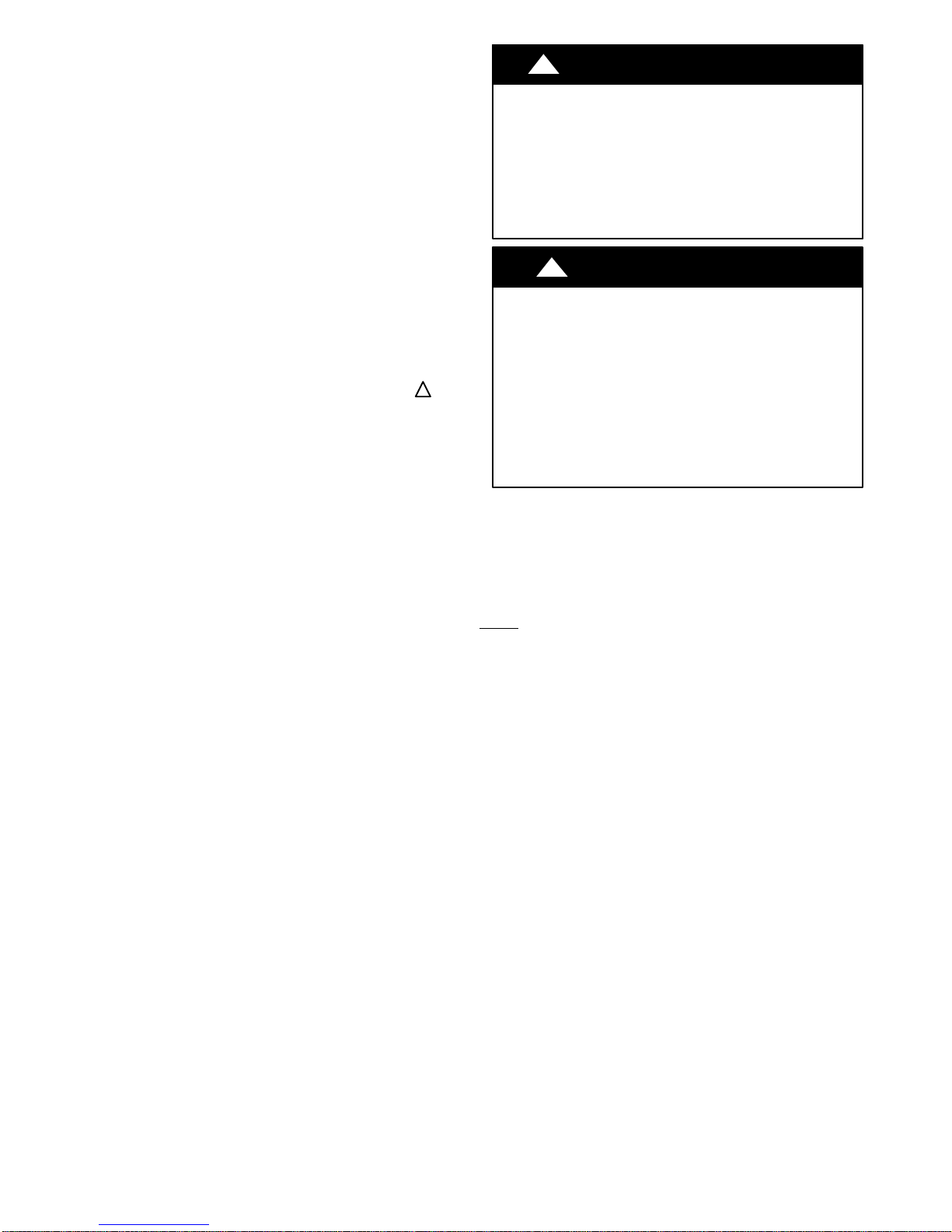
!
Recognize safety information. This is the safety−alert symbol
When you see this symbol on the unit and in instructions or manuals,
be alert to the potential for personal injury.Understand these signal
words: DANGER, WARNING, and CAUTION. These words are used
with the safety−alert symbol. DANGER identifies the most serious
hazards which will result in severe personal injury or death. WARNING
signifies hazards which could result in personal injury or death.
CAUTION is used to identify unsafe practices which may result in
minor personal injury or product and property damage. NOTE is used
to highlight suggestions which will result in enhanced installation,
reliability, or operation.
!
.
!
ELECTRICAL SHOCK HAZARD
Failure to follow this warning could result in personal
injury or death.
Before installing, modifying, or servicing system, main
electrical disconnect switch must be in the OFF
position. There may be more than 1 disconnect switch.
Lock out and tag switch with a suitable warning label.
!
EQUIPMENT DAMAGE HAZARD
Failure to follow this caution may result in equipment
damage or improper operation.
Do not bury more than 36 in. (914 mm) of refrigerant pipe
in the ground. If any section of pipe is buried, there must be
a 6 in. (152 mm) vertical rise to the valve connections on
the outdoor units. If more than the recommended length is
buried, refrigerant may migrate to the cooler buried section
during extended periods of system shutdown. This causes
refrigerant slugging and could possibly damage the
compressor at start−up.
WARNING
CAUTION
GENERAL
These instructions cover the installation, start−up and servicing of
outdoor and indoor units ductless systems.
SYSTEM REQUIREMENTS
Allow sufficient space for airflow and servicing unit. See Fig. 4 for
minimum required distances between unit and walls or ceilings.
Piping
IMPORTANT: Both refrigerant lines must be insulated separately.
S Minimum refrigerant line length between the indoor and outdoor
units is 10 ft. (3 m).
S The following maximum lengths are allowed.
2 421 019420 02
Specifications subject to change without notice.

PIPING AND REFRIGERANT TABLES DLFCAB / DLCCAR / DLFCHB / DLCCHR
T able 2—Piping Information DLFCAB / DLCCAR / DLFCHB / DLCCHR
System Size 9K 12K 9K 12K 18K 24K 30K 36K
Voltage 115/1/60 115/1/60 208/230-1-60 208/230-1-60 208/230-1-60 208/230-1-60 208/230-1-60 208/230-1-60
Min. Piping
Length
Standard
Piping Length
Max. Outdoor-
Indoor Height
Difference
Max. Piping
Length w/ No
Additional
Refrigerant
Charge
Max. Piping
Length
Gas Pipe (size
- connection
type)
Liquid Pipe
(size -
connection
type)
System Size 9K 12K 9K 12K 18K 24K 30K 36K
Cooling
Only
Heat
Pump
ft 10 10 10 10 10 10 10 10
m 3 3 3 3 3 3 3 3
ft 25 25 25 25 25 25 25 25
m 7.5 7.5 7.5 7.5 7.5 7.5 7.5 7.5
ft 32.8 32.8 32.8 32.8 32.8 32.8 32.8 32.8
m 10 10 10 10 10 10 10 10
ft 25 25 25 25 25 25 25 25
m 7.5 7.5 7.5 7.5 7.5 7.5 7.5 7.5
ft 49.2 65.6 49.2 65.6 82 82 98.4 98.4
m 15 20 15 20 25 25 30 30
in 3/8 1/2 3/8 1/2 5/8 5/8 5/8 5/8
in 1/4 1/4 1/4 1/4 1/4 1/4 1/4 1/4
T able 3— Refrigerant Information DLFCAB / DLCCAR / DLFCHB / DLCCHR
Voltage 115/1/60 115/1/60 208/230-1-60 208/230-1-60 208/230-1-60 208/230-1-60 208/230-1-60 208/230-1-60
Refrigerant
Type
Charge
Amount
Additional
Refrigerant
Charge
(between
Standard –
Max Piping
Length)
Refrigerant
Type
Charge
Amount
Additional
Refrigerant
Charge
(between
Standard –
Max Piping
Length)
-- R410A R410A R410A R410A R410A R410A R410A R410A
Oz 42.3 47.6 45.9 47.6 56.4 81.1 84.66 84.7
Kg 1.2 1.35 1.3 1.35 1.6 2.3 2.4 2.4
Oz/ft 0.161 0.161 0.161 0.161 0.161 0.161 0.161 0.16
g/m 15 15 15 15 15 15 15 15
-- R410A R410A R410A R410A R410A R410A R410A R410A
Oz 42.3 47.6 45.9 47.6 56.4 77.6 84.66 91.7
kg 1.2 1.35 1.3 1.35 1.6 2.2 2.4 2.6
Oz/ft 0.215 0.215 0.215 0.215 0.161 0.538 0.538 0.54
g/m 20 20 20 20 15 50 50 50
421 019420 02 3
Specifications subject to change without notice.

PIPING AND REFRIGERANT TABLES DLFDAB / DLCDAR / DLFDHB / DLCDHR
T able 4— Piping Information DLFDAB / DLCDAR / DLFDHB / DLCDHR
System Size 9K 12K 9K 12K 18K 24K 30K* 36K*
Voltage 115/1/60 115/1/60 208/230-1-60 208/230-1-60 208/230-1-60 208/230-1-60 208/230-1-60 208/230-1-60
Min. Piping
Length
Standard
Piping Length
Max.
Outdoor-
Indoor Height
Difference
Max. Piping
Length w/ No
Additional
Refrigerant
Charge
Max. Piping
Length
Gas Pipe
(size -
connection
type)
Liquid Pipe
(size -
connection
type)
Cooling
Only
Heat
Pump
ft 10 10 10 10 10 10 10 10
m 3 3 3 3 3 3 3 3
ft 25 25 25 25 25 25 25 25
m 7.5 7.5 7.5 7.5 7.5 7.5 7.5 7.5
ft 32.8 32.8 32.8 32.8 32.8 32.8 32.8 32.8
m 10 10 10 10 10 10 10 10
ft 25 25 25 25 25 25 25 25
m 7.5 7.5 7.5 7.5 7.5 7.5 7.5 7.5
ft 65.6 65.6 49.2 49.2 82 82 98.4 98.4
m 20 20 15 15 25 25 30 30
in 3/8 3/8 3/8 3/8 1/2 5/8 5/8 5/8
in 1/4 1/4 1/4 1/4 1/4 1/4 1/4 1/4
T able 5—Refrigerant Information DLFDAB / DLCDAR / DLFDHB / DLCDHR
System Size 9K 12K 9K 12K 18K 24K 30K 36K*
Voltage 115/1/60 115/1/60 208/230-1-60 208/230-1-60 208/230-1-60 208/230-1-60 208/230-1-60 208/230-1-60
Refrigerant
Type
Charge Amount
Additional
Refrigerant
Charge
(between
Standard – Max
Piping Length)
Refrigerant
Type
Charge Amount
Additional
Refrigerant
Charge
(between
Standard – Max
Piping Length)
-- R410A R410A R410A R410A R410A R410A
oz 26.5 31.8 24.7 30 35.3 56.45
kg 0.75 0.9 0.7 0.85 1 1.6
oz/ft 0.161 0.161 0.161 0.161 0.161 0.161
g/m 15 15 15 15 15 15
-- R410A R410A R410A R410A R410A R410A R410A R410A
oz 24.7 31.8 24.7 30 49.4 65.27 84.7 92
kg 0.7 0.9 0.7 0.85 1.4 1.85 2.4 3
oz/ft 0.215 0.215 0.215 0.215 0.215 0.538 0.54 1
g/m 20 20 20 20 20 50 50 50
NOTE: * Sizes 30 and 36 not available as Cooling Only.
4 421 019420 02
Specifications subject to change without notice.
WIRING
All wires must be sized per NEC (National Electrical Code) or CEC
(Canadian Electrical Code) and local codes. Use the Electrical Data
table MCA (minimum circuit amps) and MOCP (maximum over
current protection) to correctly size the wires and the disconnect the
fuse or breakers respectively.
Per the caution note, only Stranded copper conductors with a 600 volt
rating and double insulated copper wire must be used.
NOTE: The use of BX cable is not recommended.
Recommended Connection Method for Power and
Communication
Wiring − Power and Communication Wiring:
The main power is supplied to the outdoor unit. The field supplied 14/3
power/communication wiring from the outdoor unit to the indoor unit
consists of four (4) wires and provides the power for the indoor unit.
Two wires are high voltage AC power, one is the communication
wiring and the other is a ground wire.
Recommended Connection Method for Power and
Communication Wiring (To minimize communication
wiring interference)
PowerWiring:
The main power is supplied to the outdoor unit. The field supplied
power wiring from the outdoor unit to the indoor unit consists of three
(3) wires and provides the power for the indoor unit. Two wires are
high voltage AC power and one is a ground wire.
T o minimize a voltage drop, the factory recommended wire size is 14/2
stranded with a ground.
Communication Wiring:
A separate shielded stranded copper conductor only, with a minimum
600 volt rating and double insulated copper wire, must be used as the
communication wire from the outdoor unit to the indoor unit.
Please use a separate shielded 16GA stranded control wire.
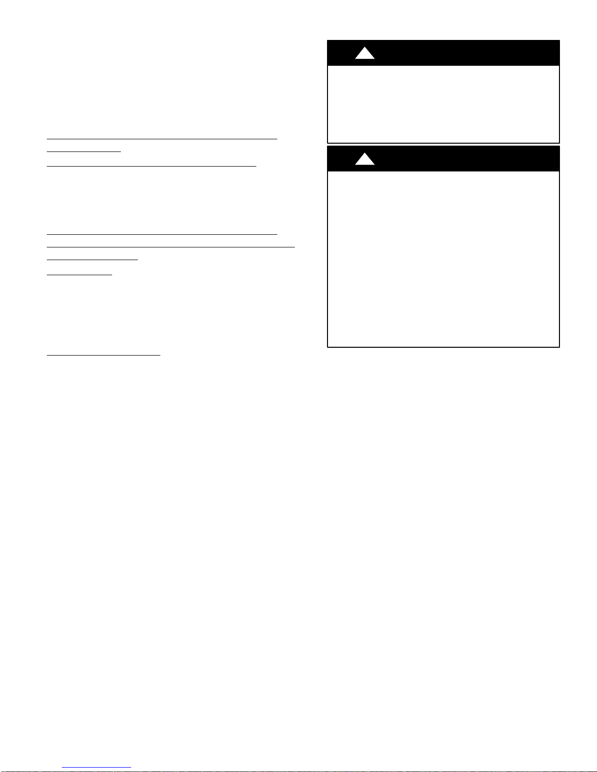
!
EQUIPMENT DAMAGE HAZARD
Failure to follow this caution may result in equipment
damage or improper operation.
S Wires should be sized based on NEC and local codes.
S Use copper conductors only with a 600 volt rating and
double insulated copper wire.
!
EQUIPMENT DAMAGE HAZARD
Failure to follow this caution may result in equipment
damage or improper operation.
S Comply with local codes while running wire from indoor
unit to outdoor unit.
S Every wire must be connected firmly. Loose wiring may
cause a terminal to overheat or result in unit
malfunction. A fire hazard may also exist. Ensure all
wiring is tightly connected.
S No wire should touch refrigerant tubing, the compressor
or any moving parts.
S Disconnecting means must be provided and must be
located within sight and readily accessible from the air
conditioner.
S Connecting the cable with conduit shall be routed
through a hole in the conduit panel.
CAUTION
CAUTION
Table 6—Electrical Data
DLFCAB - DLCCAR / DLFCHB - DLCCHR
System Size 9K 12K 9K 12K 18K 24K 30K 36K
Voltage 115/1/60 115/1/60 208/230-1-60 208/230-1-60 208/230-1-60 208/230-1-60 208/230-1-60 208/230-1-60
MCA A 12 17 9 9 16 20 20 24
MOCP A 20 25 15 15 25 30 30 40
Table 7—Electrical Data
DLFDAB - DLCDAR / DLFDHB - DLCDHR
System Size 9K 12K 9K 12K 18K 24K 30K 36K
Voltage 115/1/60 115/1/60 208/230-1-60 208/230-1-60 208/230-1-60 208/230-1-60 208/230-1-60 208/230-1-60
MCA A 17 20 9 9 16 15/16 20 24
MOCP A 25 30 15 15 25 25 30 40
421 019420 02 5
Specifications subject to change without notice.

DIMENSIONS − INDOOR
Fig. 1 - Indoor Unit Dimensions
T able 8—DLFCAB / DLCCAR / DLFCHB / DLCCHR
System Size 9K 12K 9K 12K 18K 24K 30K 36K
Voltage 115/1/60 115/1/60 208/230-1-60 208/230-1-60 208/230-1-60 208/230-1-60 208/230-1-60 208/230-1-60
Height (H) in 11.4 11.4 11.4 11.4 11.8 12.8 12.8 12.8
Width (W) in 33.3 33.3 33.3 33.3 38.2 42.4 53.1 53.1
Depth (D) in 8.2 8.2 8.2 8.2 8.8 9.7 10 10
Weight-Net lbs 23.2 23.2 22.1 22.1 27.6 34.2 41.9 41.9
T able 9—DLFDAB / DLCDAR / DLFDHB / DLCDHR
System Size 9K 12K 9K 12K 18K 24K 30K* 36K*
Voltage 115/1/60 115/1/60 208/230-1-60 208/230-1-60 208/230-1-60 208/230-1-60 208/230-1-60 208/230-1-60
Height (H) in 10.8 11.4 10.8 11.4 11.8 12.8 12.8 12.8
Width (W) in 31.1 33.3 31.1 33.3 38.2 42.4 53.1 53.1
Depth (D) in 7.9 8.2 7.9 8.2 8.8 9.7 10 10
Weight-Net lbs 19.8 22.1 19.8 23.2 29.8 37.5 41.9 41.9
A
B
C
D
E
F
D
E
H
Fig. 2 - Indoor Mounting Plate
T able 10—DLFCAB / DLCCAR / DLFCHB / DLCCHR
System Size 9K 12K 9K 12K 18K 24K 30K 36K
Voltage 115/1/60 115/1/60 208/230-1-60 208/230-1-60 208/230-1-60 208/230-1-60 208/230-1-60 208/230-1-60
A in 4.7 4.7 4.7 4.7 4.0 8.1 13.8 13.8
B in 21.3 21.3 21.3 21.3 27.0 27.0 29.4 29.4
C in 7.3 7.3 7.3 7.3 7.2 7.3 10.0 10.0
D in 2.2 2.2 2.2 2.2 2.2 2.8 2.8 2.8
E in 1.4 1.4 1.4 1.4 1.5 1.7 1.6 1.6
F in 5.0 5.0 5.0 5.0 7.5 6.0 11.6 11.6
H in 3.3 3.3 3.3 3.3 5.5 3.1 3.5 3.5
T able 11—DLFDAB / DLCDAR / DLFDHB / DLCDHR
System Size 9K 12K 9K 12K 18K 24K 30K* 36K*
Voltage 115/1/60 115/1/60 208/230-1-60 208/230-1-60 208/230-1-60 208/230-1-60 208/230-1-60 208/230-1-60
A in 6.6 4.7 6.6 4.7 4.0 8.1 13.8 13.8
B in 18.2 21.3 18.2 21.3 27.0 27.0 29.4 29.4
C in 6.3 7.3 6.3 7.3 7.2 7.3 10.0 10.0
D in 2.2 2.2 2.2 2.2 2.2 2.8 2.8 2.8
E in 2.1 1.4 2.1 1.4 1.5 1.7 1.6 1.6
F in 6.0 5.0 6.0 5.0 7.5 6.0 11.6 11.6
H in 3.5 3.3 3.5 3.3 5.5 3.1 3.5 3.5
NOTE: * Sizes 30 and 36 not available as Cooling Only.
6 421 019420 02
Specifications subject to change without notice.

DIMENSIONS − OUTDOOR
M
N
H
W
D
P
S
Fig. 3 - Outdoor Unit
T able 12—DLFCAB / DLCCAR / DLFCHB / DLCCHR
System Size 9K 12K 9K 12K 18K 24K 30K 36K
Voltage 115/1/60 115/1/60 208/230-1-60 208/230-1-60 208/230-1-60 208/230-1-60 208/230-1-60 208/230-1-60
Height (H) in 21.3 23.3 21.3 23.3 27.6 31.1 31.1 31.1
Width (W) in 33.4 33.4 33.4 33.4 37.6 38.6 38.6 38.6
Depth (D) in 12.6 12.6 12.6 12.6 15.6 16.8 16.8 16.8
M in 10.0 10.0 10.0 10.0 13.4 14.6 14.6 14.6
N in 30.0 30.0 30.0 30.0 35.0 36.2 36.2 36.2
P in 21.3 21.3 21.3 21.3 22.0 24.0 24.0 24.0
S in 11.3 11.3 11.3 11.3 14.3 15.6 15.6 15.6
NET Weight
Cooling
Only
NET Weight
Heat Pump
lbs 62.8 73.9 72.8 80.5 113.6 147.7 152.1 154.4
lbs 71.7 77.2 78.3 86 114.7 142.2 154.4 161
T able 13—DLFDAB / DLCDAR / DLFDHB / DLCDHR
System Size 9K 12K 9K 12K 18K 24K 30K* 36K*
Voltage 115/1/60 115/1/60 208/230-1-60 208/230-1-60 208/230-1-60 208/230-1-60 208/230-1-60 208/230-1-60
Height (H) in 21.3 21.3 21.3 21.3 27.6 27.6
Width (W) in 30.6 30.6 30.6 30.6 37.6 37.6
Depth (D) in 12.6 12.6 12.6 12.6 15.6 15.6
M in 10.1 10.1 10.1 10.1 13.4 13.4 14.6 14.6
N in 28.0 28.0 28.0 28.0 35.0 35.0 36.2 36.2
P in 20.0 20.0 20.0 20.0 22.0 22.0 24.0 24.0
S in 11.3 11.3 11.3 11.3 14.3 14.3 15.6 15.6
NET Weight
Cooling
Only
NET Weight
Heat Pump
lbs 59.5 63.9 66.2 70.6 90.4 103.6
lbs 62.8 67.3 65.0 69.5 95.9 110.3 154.4 161.0
NOTE: * Sizes 30 and 36 not available as Cooling Only.
421 019420 02 7
Specifications subject to change without notice.

CLEARANCES − INDOOR
(0.13m)
"
5
min.
CEILING
6" (0.15m) min.
(1.8m)
6'
FLOOR
Fig. 4 - Indoor Unit Clearances
5
"
(0.13m)
min.
CLEARANCES − OUTDOOR
D
UNIT
A 24 (609)
B 24 (609)
C 24 (609)
D 4 (101)
E 4 (101)
A
Air-inlet
E
B
C
Air-outlet
Fig. 5 - Outdoor Unit Clearances
T able 14—Outdoor Clearances
Minimum Value in. (mm)
8 421 019420 02
Specifications subject to change without notice.

INSTALLATION GUIDE
)
I
Ideal installation locations include:
Indoor Unit
S A location where there are no obstacles near inlet and outlet area.
S A location which can bear the weight of indoor unit.
S Do not install indoor units near a direct source of heat such as direct
sunlight or a heating appliance.
S A location which provides appropriate clearances as outlined in Fig.
4. Be sure to leave enough distance to allow access for routine
maintenance. The installation site should be 72” or more above the
floor.
S Select a place away from potential electronic interference.
S Select a place where the filter can be easily removed.
Outdoor Unit
S A location which is convenient to installation and not exposed to
strong wind.
S A location which can bear the weight of outdoor unit and where the
outdoor unit can be mounted in a level position.
S A location which provides appropriate clearances as outlined in Fig.
4.
S Do not install the indoor or outdoor units in a location with special
environmental conditions.
S Make sure the outdoor unit is installed in accordance with the
installation instructions and is convenient for maintenance and repair.
S See the refrigerant piping table for the maximum height difference
between indoor and outdoor units and the maximum length of the
connecting tubing.
INDOOR UNIT INSTALLATION
INSTALL MOUNTING PLATE
1. Carefully remove the mounting plate from the unit box.
2. The mounting plate should be located horizontally and level on
the wall. All minimum spacings shown in Fig. 2.
3. If the wall is block, brick, concrete or similar material, drill .2”
(5 mm) diameter holes and insert anchors for the appropriate
mounting screws.
4. Attach the mounting plate to the wall.
DRILL HOLD IN WALL FOR INTERCONNECTING
PIPING, DRAIN AND WIRING
Refrigerant Line Routing
The refrigerant lines may be routed in any of the four directions shown
in Fig. 6.
For maximum serviceability, it is recommended to have refrigerant line
flare connections and the drain connection on the outside of the wall
that the fan coil is mounted on.
rear left.
If piping is going through the back:
1. Determine pipe hole position using the mounting plate as a
template. Drill pipe hole diameter per chart below. The outside
pipe hole is 1/2−in. (13 mm) min. lower than inside pipe hole, so
it slants slightly downward.
If piping is going to exit from the left rear, it is recommended to
field−fabricate piping extensions to get the flare connections to
the outside of the wall.
1/2 in. (13 mm
Min.
NDOOR
Fig. 8 - Drill Holes
Table 15—Hole Diameter
Model Size Hole Diameter in. (mm)
9K, 12K, 18K, 24K 2.2 (56)
30K & 36K 2.75 (70)
If piping is going through the right or left side:
1. Use a small saw blade to carefully remove the corresponding
plastic covering on side panel and drill the appropriate size hole
where the pipe is going through the wall. See Fig. 14.
2. Remove knockout (see Fig. 7).
NOTE: If required, a condensate pump is available for the application.
OUTDOOR
A07371
OUTDOOR UNIT INSTALLATION
1. Use a rigid base to support unit in a level position.
2. Locate outdoor unit and connect piping and wiring.
!
EQUIPMENT DAMAGE HAZARD
Failure to follow this caution may result in equipment
damage or improper operation.
Excessive torque can break flare nut depending on
installation conditions.
Piping Connections to Outdoor Unit
IMPORTANT: Use refrigeration grade tubing ONLY. No other type
of tubing may be used. Use of other types of tubing will void
manufacturer’s warranty.
Ensure ther e is enough piping to cover the required length between
the outdoor and indoor unit.
Only use piping suitable for high side pressure for both high side
and low side connections.
CAUTION
left
rear right
right
Fig. 6 - Refrigerant Line Routing
left right
cut off
the hole
Fig. 7 - Refrigerant Line Routing
421 019420 02 9
rear left
A12585
Specifications subject to change without notice.

Piping Guide:
S Do not open service valves or remove protective caps from tubing
ends until all the connections are made.
S Bend tubing with bending tools to avoid kinks and flat spots.
S Keep the tubing free of dirt, sand, moisture, and other contaminants
to avoid damaging the refrigerant system.
S Avoid sags in the suction line to prevent the formation of oil
traps.
Insulate each tube with minimum 3/8−in. (10 mm) wall thermal pipe
insulation.
Inserting the tubing into the insulation before making the
connections saves time and improves installation quality.
1. Remove service valve cover if provided with unit.
2. Cut tubing with tubing cutter.
3. Install correct size flare nut onto tubing and make flare
connection.
4. Apply a small amount of refrigerant oil to the flare connection
on the tubing.
5. Properly align tubing in with service valve.
6. Tighten flare nut and finish installation using two wrenches as
shown in Fig. 9.
Outdoor Unit W iring Connections
1. Mount outdoor power disconnect.
2. Run power wiring from main box to disconnect per NEC and
local codes. Set outdoor unit in place.
3. Remove field wiring cover from unit by removing screws.
4. Connect conduit to the conduit panel (see Fig. 11).
5. Properly connect both power supply and control lines to
terminal block per the connection diagram.
6. Ground unit in accordance with NEC and local electrical codes.
7. Use lock nuts to secure conduit.
8. Reinstall field wiring cover.
Field Wiring Cover
Conduit Panel
lock nut
Fig. 9 - Tighten Flare Nut
Strong
wind
Fig. 10 - High Wind Installation
A07354
A07350
conduit
Finish
Fig. 11 - Field Wiring
!
CAUTION
EQUIPMENT DAMAGE HAZARD
Failure to follow this caution may result in equipment
damage or improper operation.
S Be sure to comply with local codes while running wire
from indoor unit to outdoor unit.
S Every wire must be connected firmly. Loose wiring may
cause terminal to overheat or result in unit malfunction.
A fire hazard may also exist. Therefore, be sure all wiring
is tightly connected.
S No wire should be allowed to touch refrigerant tubing,
compressor or any moving parts.
S Disconnecting means must be provided and shall be
located within sight and readily accessible from the air
conditioner.
S Connecting cable with conduit shall be routed through
hole in the conduit panel.
A12539
10 421 019420 02
Specifications subject to change without notice.

INSTALL ALL POWER, INTERCONNECTING
t
WIRING, AND PIPING TO INDOOR UNIT
1. Run interconnecting piping and wiring from outdoor unit to
indoor unit.
2. Pass interconnecting cable through hole in wall (outside to
inside).
3. Lift indoor unit into position and route piping and drain through
hole in wall (inside to outside). Fit interconnecting wiring into
back side of indoor unit.
4. Hang indoor unit on upper hooks of wall mounting plate (as
shown in Fig. 12 and Fig. 15).
A08283
Fig. 12 - Hanging Indoor Unit
5. Open front cover of indoor unit and remove field wiring terminal block cover (see Fig. 13).
Field iring
Coer
Interconnecting
Cable
A08279
Fig. 13 - Field Wiring Cover
6. Pull interconnecting wire up from back of indoor unit and position in close to the terminal block on indoor unit.
7. Push bottom of indoor unit onto mounting plate to complete
wall mount.
8. Connect wiring from outdoor unit per connection diagram (see
Fig. 21).
NOTE: Polarity of power wires must match original connection on
outdoor unit.
9. Replace field wiring cover and close front cover of indoor unit.
10. Connect refrigerant piping and drain line outside of indoor unit.
Refer to Fig. 9 for proper installation of flare connections.
Complete pipe insulation at flare connection then fasten piping
and wiring to the wall as required. Completely seal the hole in
the wall.
left right
Fixing hook
Mounting
plate
Mounting
plate
A12408
Fig. 15 - Hang Indoor Unit
!
CAUTION
UNIT DAMAGE HAZARD
Failure to follow this caution may result in equipment
damage or improper operation.
Never use the system compressor as a vacuum pump.
Refrigerant tubes and indoor coil should be evacuated using the
recommended deep vacuum method of 500 microns. The alternate
triple evacuation method may be used if the procedure outlined below
is followed. Always break a vacuum with dry nitrogen.
SYSTEM VACUUM AND CHARGE
Using Vacuum Pump
1. Completely tighten flare nuts A, B, C, D, connect manifold gage
charge hose to a charge port of the low side service valve (see
Fig. 16.)
2. Connect charge hose to vacuum pump.
3. Fully open the low side of manifold gage (see Fig. 17).
4. Start vacuum pump
5. Evacuate using either deep vacuum or triple evacuation method.
6. After evacuation is complete, fully close the low side of manifold gage and stop operation of vacuum pump.
7. The factory charge contained in the outdoor unit is good for up
to 25 ft. (8 m) of line length. For refrigerant lines longer than 25
ft (8 m), add 0.2 oz. per foot of extra piping up to the maximum
allowable length.
8. Disconnect charge hose from charge connection of the low side
service valve.
9. Fully open service valves B and A.
10. Securely tighten caps of service valves.
Outdoor Unit
Service Valve
Refrigerant
Low Side
A
High Side
B
Fig. 16 - Service Valve
Indoor Uni
C
D
A07360
cut off
the hole
Fig. 14 - Remove Knockouts
421 019420 02 11
Specifications subject to change without notice.

Manifold Gage
500 microns
Low side valve
Charge hose
Low side valve
High side valve
Charge hose
Vacuum pump
A07361
Fig. 17 - Manifold
Deep Vacuum Method
The deep vacuum method requires a vacuum pump capable of pulling a
vacuum of 500 microns and a vacuum gage capable of accurately
measuring this vacuum depth. The deep vacuum method is the most
positive way of assuring a system is free of air and liquid water. (See
Fig. 18)
5000
4500
4000
3500
3000
LEAK IN
SYSTEM
2500
2000
MICRONS
1500
1000
500
V ACUUM TIGHT
TOO WET
TIGHT
DRY SYSTEM
01234567
MINUTES
A95424
Fig. 18 - Deep Vacuum Graph
Triple Evacuation Method
The triple evacuation method should only be used when vacuum pump
is only capable of pumping down to 28 in. of mercury vacuum and
system does not contain any liquid water.
Refer to Fig. 19 and proceed as follows:
1. Pump system down to 28 in. of mercury and allow pump to continue operating for an additional 15 minutes.
2. Close service valves and shut off vacuum pump.
3. Connect a nitrogen cylinder and regulator to system and open
until system pressure is 2 psig.
4. Close service valve and allow system to stand for 1 hr. During
this time, dry nitrogen will be able to diffuse throughout the
system absorbing moisture.
5. Repeat this procedure as indicated in Fig. 19. The system is then
free of any contaminants and water vapor.
EVACUATE
BREAK VACUUM WITH DRY NITROGEN
WAIT
EVACUATE
BREAK VACUUM WITH DRY NITROGEN
WAIT
EVACUATE
CHECK FOR TIGHT, DRY SYSTEM
(IF IT HOLDS DEEP VACUUM)
RELEASE CHARGE INTO SYSTEM
A95425
Fig. 19 - Triple Evacuation Method
Final Tubing Check
IMPORTANT: Check to be certain factory tubing on both indoor and
outdoor unit has not shifted during shipment. Ensure tubes are not
rubbing against each other or any sheet metal. Pay close attention to
feeder tubes, making sure wire ties on feeder tubes are secure and tight.
12 421 019420 02
Specifications subject to change without notice.

STAR T−UP
T est Operation
Perform test operation after completing gas leak and electrical safety
check.
1. Push the “ON/OFF” button on Remote Control to begin testing.
NOTE: A protection feature prevents the air conditioner from being
activated for approximately 3 minutes.
2. Push MODE button, select COOLING, HEATING, FAN mode
to check if all functions work correctly.
SYSTEM CHECKS
1. Conceal the tubing where possible.
2. Make sure that the drain tube slopes downward along its entire
length.
3. Ensure all tubing and connections are properly insulated.
4. Fasten tubes to the outside wall, when possible.
5. Seal the hole through which the cables and tubing pass.
INDOOR UNIT
1. Do all Remote Control buttons function properly?
2. Do the display panel lights work properly?
3. Does the air deflection louver function properly?
4. Does the drain work?
OUTDOOR UNIT
1. Are there unusual noises or vibrations during operation?
Explain Following Items To Customer With The Aid Of The
Owner’s Manual:
1. How to turn air conditioner on and off; selecting COOLING,
HEATING and other operating modes; setting a desired
temperature; setting the timer to automatically start and stop air
conditioner operation; and all other features of the Remote
Control and display panel.
2. How to remove and clean the air filter.
3. How to set air deflection louver.
4. Explain care and maintenance.
5. Present the Owner’s Manual and installation instructions to
customer.
INSTALLATION AND MAINTENANCE OF FILTER
1. Grasp the front panel by its two ends and lift the panel and then
remove the air filter.
2. Install a clean air filter along the arrow direction and close the
panel.
Air filter
Auxiliary filter
A12541
Fig. 20 - Install Air Filter
421 019420 02 13
Specifications subject to change without notice.

WIRING DIAGRAMS
Power to
Indoor Unit
Outdoor
Unit
Terminal
Block
Control to
Indoor Unit
Power to
Indoor Unit
Power to
Indoor Unit
Control to
Indoor Unit
Main Power
Supply
Power to
Indoor Unit
DLF/DLC*09&12J 115-1-60 Connection Diagram
CONNECTING CABLE
OUTDOOR TO INDOOR
CAUTION
CAUTION
Atte nti on
Atte nti on
Use Cop per Co nduc tor s O nly
Use Cop per Co nduc tor s O nly
With Minimum300 Volt, 2/64"
With Minimum300 Volt, 2/64"
Thick Insula tion.
Main Power
Supply
Ground
Thick Insula tion.
Utilisez seulementdes
Utilisez seulementdes
conduct eurs en cuivre d'un
conduct eurs en cuivre d'un
minimum de 30 0 volt d'une
minimum de 30 0 volt d'une
isolation d' èpaisseur de 2/64".
isolation d' èpaisseur de 2/64".
Fig. 21 - 09K & 12K 115V Unit Wiring Diagrams
DLF/DLC*09&12K 208/230-1-60 Connection Diagram
CONNECTING CABLE
OUTDOOR TO INDOOR
CAUTION
Att ent ion
Use Copper Conduct ors Only
Ground
With Minimum 300 Volt, 2/64"
Thick Ins ulati on.
Utilisez se ulement des
conducteurs en cuivre d'un
minimum de 300 volt d'une
isolation d' èpaisseur de 2 /64".
Power from
Outdoor
Unit
Power from
Outdoor
Control
from
Outdoor
Unit
Unit
Control
from
Outdoor
Unit
Power from
Outdoor
Unit
06-1-032/802CDVwoL06-1-032/802CDVwoL
Power from
Outdoor
DNG'1LS'2LDNG'1LS'2L
Ground
Unit
DNG'LS'NDNGNL'LS'N
Ground
06-1-511CDVwoL06-1-51106-1-51106-1-51106-1-511CDVwoL06-1-511
kcolBlanimreTtinUroodnIJ21&90*FLDkcolBlanimreTtinUroodtuOJ21&90*CLD
Indoor
Unit
Terminal
Block
L2 L1 GND
Main Power
Supply
208/230-1-60 208/230-1-60
Main Power
Supply
Ground
Fig. 22 - 09K & 12K 208/230V Unit Wiring Diagrams
DLF/DLC*18-36 208/230-1-60 Connection Diagram
CONNECTING CABLE
OUTDOOR TO INDOOR
Use Copper Conductor s Only
Use Copper Conductor s Only
With Minimum 300 Volt,2/64"
With Minimum 300 Volt,2/64"
Thick Insula tion.
Power to
Indoor Unit
Control to
Indoor Unit
Power to
Indoor Unit
Main Power
Supply
Main Power
Supply
Ground
Thick Insula tion.
Utili sez s eul em ent de s
Utili sez s eul em ent de s
conducteurs en cuivred'un
conducteurs en cuivred'un
minimum de 300 volt d'une
minimum de 300 volt d'une
isolat ion d' è paiss eur de 2/64 ".
isolat ion d' è paiss eur de 2/64 ".
Fig. 23 - 18K & 36K 208/230V Unit Wiring Diagrams
NOTE: Polarity of power wires must match original connection on outdoor unit.
CAUTION
CAUTION
Attention
Attention
Power from
Outdoor
Unit
Control
from
Outdoor
Unit
Power from
Outdoor
Unit
DNG'1LS'2LDNG2L1L'1LS'2L
Ground
06-1-032/802CDVwoL06-1-032/80206-1-032/80206-1-032/80206-1-032/802CDVwoL06-1-032/802
kcolBlanimreTtinUroodnI63-81*FLDkcolBlanimreTtinUroodtuO63-81*CLD
14 421 019420 02
Specifications subject to change without notice.

TROUBLESHOOTING
This unit has on−board diagnostics. Error codes appear on the LED display on the front panel of the indoor unit in place of the temperature display.
Error codes are also displayed on the outdoor unit microprocessor board with colored LED lights. The table below explains the error codes for both
units.
T able 16—Diagnostic Codes
Display of lamp (the times of blinking)
Malfunction Display of Indoor Unit
Anti-freezing protection E2 2 3
Block or Low pressure of refrigerant system E3 3 9
Compressor exhaust high temperature protection E4 4 7
AC over-current protection E5 5 5
Communication failure between indoor unit and outdoor unit E6 6 O/U
Anti-high temperature protection
No feedback of indoor fan motor H6 11
Jumper cap malfunction protection C5 15
Indoor unit and outdoor unit doesn't match LP 19 16
Outdoor DC fan motor malfunction L3 23 14
Power protection L9 20 9
Gathering refrigerant Fo 1 1
Indoor ambient sensor open or short circuit F1 1
Indoor tube sensor open or short circuit F2 2
Outdoor ambient sensor open or short circuit F3 3 6
Outdoor tube sensor open or short circuit F4 4 5
Exhaust sensor open or short circuit F5 5 7
Overload limit / drop frequency F6 6 3
Over current limit / drop frequency F8 8 1
High exhaust temperature limit / drop frequency F9 9 2
Refrigerant leakage protection F0 10 9
Anti-freezing limit / drop frequency FH 2 2 4
Defrosting H1 1 2
Compressor overload protection H3 3 8
IPM protection H5 5 4
Module temperature is too high H5 5 10
PFC protection HC 6 14
Loading EEPROM malfunction EE 15 11
High PN voltage protection PH 11 13
Low PN voltage protection PL 21 12
4-way valve reversal abnormal U7 20
DRED1 / DRED2 / DRED3 d1/d2/d3
Compressor Min frequence in test state P0
Compressor rated frequence in test state P1
Compressor maximum frequence in test state P2
Compressor intermediate frequence in test state P3
Compressor is running(normal) 1
The temperature for turning on the unit is reached (normal) 8
Frequency limiting (module temperature) EU 6 6 11
Frequency limiting (power) LU 24 13
R (Indoor)--Running
C--Cooling
Y--Yellow
R (Outdoor)--Red
G--Green
O/U--OFF or Unblink. The display difference between Fo and F0 is 'o' is the bottom part of Fig. 8
E8 8 6
H4 4 6
Indoor Outdoor
R C H Y R G
421 019420 02 15
Specifications subject to change without notice.

Copyright 2016 International Comfort Products
Lewisburg, TN 37091
16 421 019420 02
Specifications subject to change without notice.
 Loading...