


SERVICE MANUAL
R−410A Ductless Split System
Air Conditioner and Heat Pump
MODELS: DLC4(A/H)6−Outdoor, DLF4(A/H)6−Indoor
SIZES: 9K, 12K, 18K, and 24K
INTRODUCTION
This Service Manual provides the necessary information to
service, repair, and maintain the DLF4(A,H), DLC4(A/H)
TABLE OF CONTENTS PAGE
SAFETY CONSIDERATIONS 1........................
MODEL / SERIAL NUMBER NOMENCLATURE 2........
STANDARD FEATURES AND ACCESSORIES 3.........
PHYSICAL DATA 4−7.................................
AHRI CAPACITY RATINGS 8..........................
AIRTHROW DATA 8..................................
SOUND RATINGS 9..................................
DIMENSIONS − INDOOR 10...........................
DIMENSIONS − OUTDOOR 11........................
CLEARANCES 13....................................
SYSTEM OPERATING ENVELOPE 14.................
ELECTRICAL DATA 17...............................
CONNECTION DIAGRAMS 18.........................
WIRING DIAGRAMS 19...............................
REFRIGERATION SYSTEM DIAGRAM 23...............
SYSTEM EVACUATION AND CHARGING 25............
REMOTE CONTROL AND FUNCTIONS 26−27...........
FUNCTION AND CONTROLS 28−31....................
TROUBLESHOOTING 32−59..........................
APPENDIX TABLES 60−62...........................
UNIT REMOVAL PROCEDURES 63....................
Indoor 9k − 12k 115v 64.................................
Outdoor 9k − 12k 115v 75...............................
Indoor 12k − 18k 230v 79................................
Outdoor 12k 230v 85...................................
Outdoor 18k 230v 90...................................
Indoor 24k 230v 96.....................................
Outdoor 24k 230v 102..................................
service agency, or your distributor or branch for information
or assistance. The qualified installer or agency must use
factory−authorized kits or accessories when modifying this
product. Refer to the individual instructions packaged with
the kits or accessories when installing.
Follow all safety codes. Wear safety glasses, protective
clothing, and work gloves. Use quenching cloth for brazing
operations. Have fire extinguisher available. Read these
instructions thoroughly and follow all warnings or cautions
included in literature and attached to the unit. Consult local
building codes and National Electrical Code (NEC) for
special requirements.
Recognize safety information. This is the safety−alert
!
!
symbol
instructions or manuals, be alert to the potential for personal
injury.
Understand these signal words: DANGER, WARNING, and
CAUTION. These words are used with the safety−alert
symbol. DANGER identifies the most serious hazards which
will result in severe personal injury or death. WARNING
signifies hazards which could result in personal injury or
death. CAUTION is used to identify unsafe practices which
may result in minor personal injury or product and property
damage. NOTE is used to highlight suggestions which will
result in enhanced installation, reliability, or operation.
ELECTRICAL SHOCK HAZARD
Failure to follow this warning could result in personal
injury or death.
Before installing, modifying, or servicing system, main
electrical disconnect switch must be in the OFF
position. There may be more than 1 disconnect switch.
Lock out and tag switch with a suitable warning label.
When you see this symbol on the unit and in
!
WARNING
!
WARNING
EXPLOSION HAZARD
Failure to follow this warning could
result in death, serious personal
injury, and/or property damage.
Never use air or gases containing
oxygen for leak testing or
operating refrigerant compressors.
Pressurized mixtures of air or
gases containing oxygen can lead
to an explosion.
SAFETY CONSIDERATIONS
Improper installation, adjustment, alteration, service,
maintenance, or use can cause explosion, fire, electrical
shock, or other conditions which may cause death, personal
injury, or property damage. Consult a qualified installer,
!
EQUIPMENT DAMAGE HAZARD
Failure to follow this caution may result in equipment
damage or improper operation.
Do not bury more than 36 in. (914 mm) of refrigerant
pipe in the ground. If any section of pipe is buried, there
must be a 6 in. (152 mm) vertical rise to the valve
connections on the outdoor units. If more than the
recommended length is buried, refrigerant may migrate
to the cooler buried section during extended periods of
system shutdown. This causes refrigerant slugging and
could possibly damage the compressor at start−up.
CAUTION
421 08 9205 00 2/21/14
MODEL NOMENCLATURE
MODEL SERIES
Position Number 1 2 3 4 5 6 7 8 9 10 11
DLC = Outdoor
DLF = Indoor Outdoor/Indoor
4A6 = AC
4H6 = HP
09 = 9k BTU
12 = 12k BTU
18 = 18k BTU
24 = 24k BTU
J = 115−1−60
K = 208/230−1−60
1A Factory Designation
D L C 4 A 6 0 9 J 1 A
Type
Size
Voltage
2 421 01 9204 01
STANDARD FEATURES AND ACCESSORIES
Ease Of Installation
Mounting Brackets S
Low Voltage Controls S
Comfort Features
Microprocessor Controls S
Wireless Remote Control S
Rapid Cooling/Heating S
Automatic Air Sweep S
Cold Blow Prevention S
Continuous Fan * S
Auto Restart Feature S
Memory Function S
Auto Changeover on Heat Pumps S
Dry Function S
Energy Saving Features
Inverter Driven Compressor S
Sleep Mode S
24 Hour Stop/Start Timer S
Safety And Reliability
Indoor Unit Freeze Protection S
3 Minute Compressor Time Delay S
High Compressor Discharge Temperature S
Low Voltage Protection S
Compressor Overload Protection S
Compressor Over current Protection S
IPM Module Protection S
Ease Of Service And Maintenance
Cleanable Filters S
Diagnostic LED’s On Outdoor Board S
Error Messages Displayed Front Panel S
Application Flexibility
Condensate Pump A
Standard Warranty
7 Year Compressor Limited Warranty** S
5 Year Parts Limited Warranty** S
Legend
S Standard
A Accessory
O Optional
F Field Fabricated
* Cooling Only
** For owner occupied residential applications.
For Commercial applications, warranty is 1 year parts and 5 years
compressor.
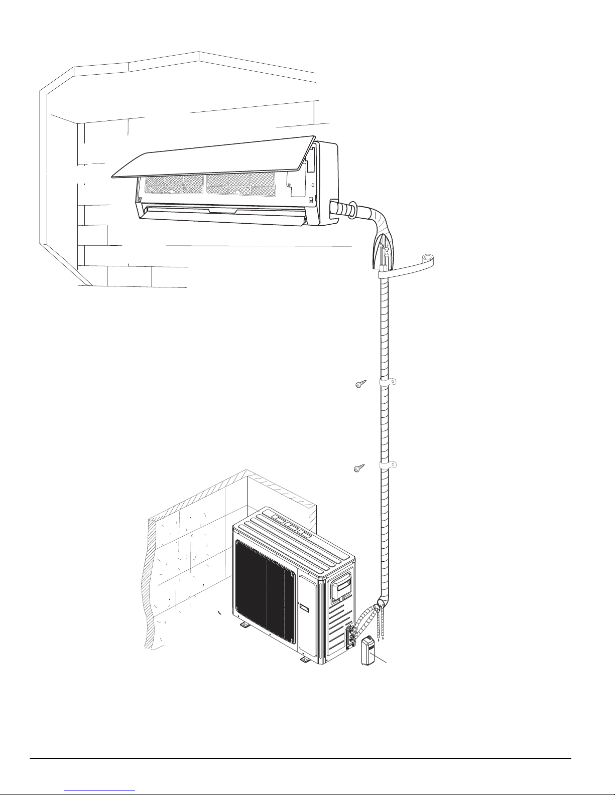
INDOOR UNITS
On high wall fan coils, the condensate pump accessory is
recommended when adequate drain line pitch cannot be
provided, or when the condensate must move up to exit.
The pump has a lift capability of 12 ft (3.6 m) on the discharge
side if the pump is mounted in the fan coil or 6 ft (1.8 m) on the
suction side if the pump is remote mounted.
16 ft Transparent Suction/Discharge Tubing 1
Condensate Pump Assembly 1
Low voltage Power Cord 1
Transparent Detection Unit Vent Tubing 1
Power Cable 1
Wire Ties 6
Wall Mount Bracket 1
Adhesive 1
Detection Unit Mounting Bracket 1
⅝-in Rubber Elbow 1
Detection Unit 1
ELECTRICAL SHOCK HAZARD
Failure to follow this warning could result in personal injury
or death.
Before installing, modifying, or servicing system, main
electrical disconnect switch must be in the OFF position.
There may be more than one disconnect switch. Lock out
and tag switch with a suitable warning label.
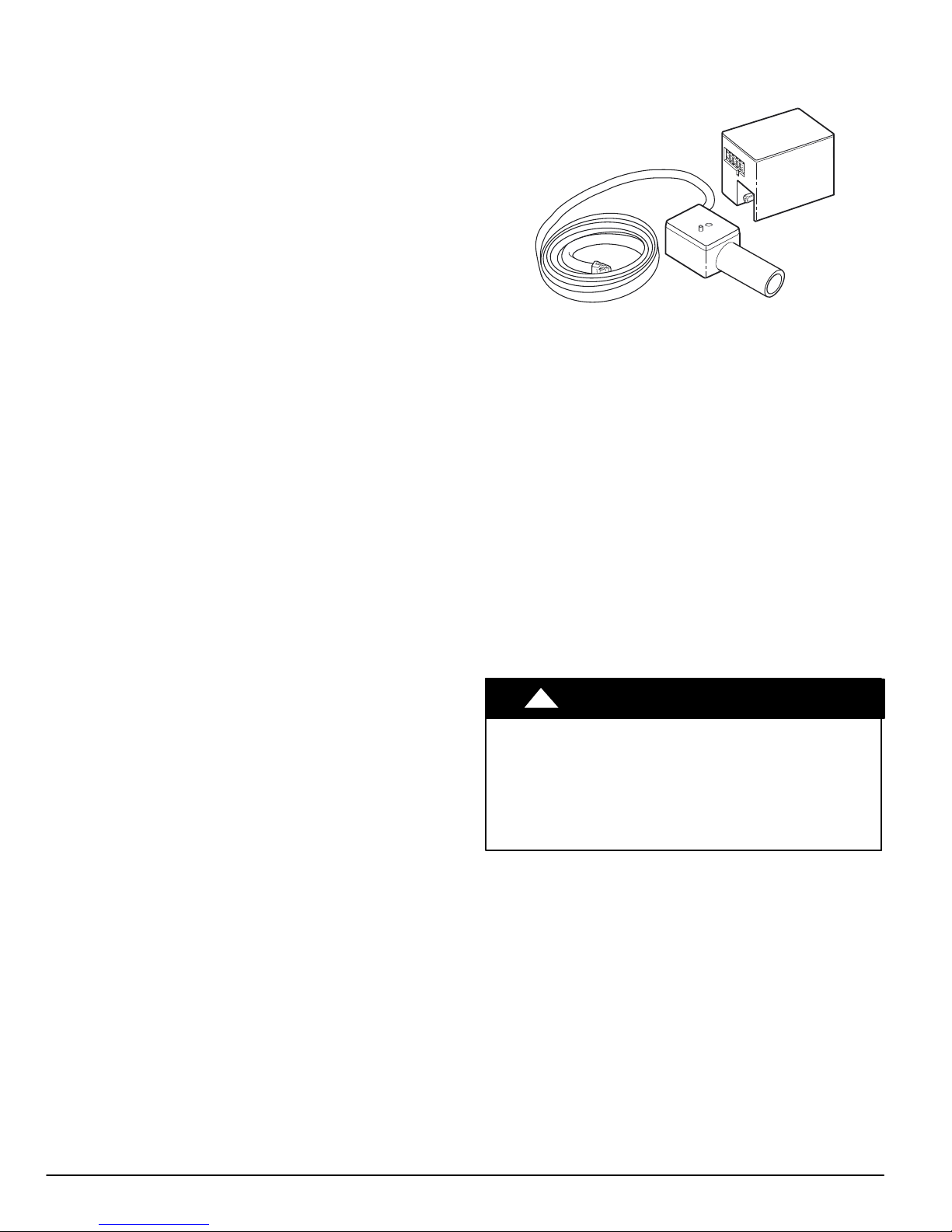
Figure 1 - Condensate Pump Accessory
Table 1—Accessory Condensate Pump Kit Contents
Item Qty.
!
WARNING
A07892
3 421 08 9205 00

PHYSICAL DATA − DLC4A6
Outdoor Unit DLC4A6 09 12 12 18 24
System Voltage 115-1-60 208/230-1-60
Control Voltage Low Voltage Pulse DC
Rated Cooling Capacity (Btuh) 9,000 11,800 12,000 18,000 22,000
Cooling. Capacity Range
Min - Max (Btuh)
Operating Weight lb. (kg) 75 (34) 63.8 (30) 112.2 (51)
Refrigerant Type R-410A
Metering Device @ Outdoor Unit Cap. Tube EXV
Charge lb. (kg) 2.3 (1.05) 2.8 (1.27) 2.2 (1.0) 2.8 (1.27) 3.4 (1.55)
Compressor
Type Twin Rotary Inverter Driven
Model KNB092FHBMC QXA-B096ZC190 SNB130FGYMC C-6RZ146H1A
Outdoor Fan
CFM 1060 942 1880 1880
RPM 850 880 690 690
Diameter (in) 15.7 14.6 20.5 20.5
Watts 30 21 60
Outdoor Coil
Face Area (sq.) 4.4 3.7 5.9 6.1
No. Rows 2
Fins per inch 16 18
Refrigerant Lines
Connection Type Flare
Liquid (Mix Phase) in OD 1/4"
Vapor Line in OD 3/8" 1/2"
Maximum Length ft. 50 65 50 82
Max Lift (Fan Coil Above) ft. 33
Max Drop (Fan Coil Below) ft. 33
External Finish White
3,500-11,000 3,300-12,500 3,300-12,500 4,500-21,000 6,400-24,000
421 08 9205 00 4

PHYSICAL DATA CONTINUED − DLF4A6
Indoor Unit DLF4A6 09 12 12 18 24
System Voltage 115 V 208/230-1-60
Control Voltage Low Voltage Pulse DC
Electrical Connections Indoor Unit Powered From Outdoor Unit
Rated Cooling Capacity (Btuh) 9,000 11,800 12,000 18,000 22,000
Operating Weight lb. (kg) 18.7 (8.5) 19.8 (9.0) 26.5 (12.0) 33.1 (15.0)
Refrigerant Type R-410A
Metering Device @ Outdoor Unit Cap. Tube EXV
Moisture Removal Rate (pints/hr.) 1.7 2.9 2.9 3.8 4.5
Indoor Fan
RPM/CFM (Turbo) - Cooling 1300/330 1350/341 1350/341 1400/471 1350/588
RPM/CFM (High) - Cooling 1100/277 1150/288 1150/288 1150/400 1150/471
RPM/CFM (Medium) - Cooling 900/224 950/235 950/235 1000/330 1000/412
RPM/CFM (Low) - Cooling 700/188 750/200 750/200 850/271 850/353
Motor Watts 15 20 35
Blower Quantity … Size (DxL) in 1 … 3.62 x 23.4 1 … 3.9 x 25.6 1 … 3.9 x 30.1
Indoor Coil
Face Area (sq.) 1.93 2.2 2.8
No. Of Rows 2
Fins Per Inch 18 17
Filters
Quantity 2 2 2 2
Controls Integrated Microprocessor
Wireless Remote Standard
Modes Cool/Heat/Dry/Auto
Fan Mode High/Medium/Low/Auto
Emergency Mode Yes
Defrost Method Demand Defrost
Diagnostics Yes
Air Sweep Yes
Soft Start Yes
Rapid Cooling/Heating Ye s
Cold Blow Prevention Yes
Sleep Mode Yes
24 Hour Timer Yes
Auto Restart Yes
Freeze Protection On Indoor Unit Yes
Refrigerant Lines
Connection Type Flare
Liquid (Mix Phase) in OD 1/4"
Vapor Line in OD 3/8" 1/2"
Maximum Length ft. 50 65 50 82
Max Lift (Fan Coil Above) ft. 33
Max Drop (Fan Coil Below) ft. 33
Condensate Drain
Size in ID = 1/2" OD = 5/8"
External Finish White
5 421 08 9205 00

PHYSICAL DATA CONTINUED − DLC4H6
Outdoor Unit DLC4H6 09 12 12 18 24
System Voltage 115-1-60 208/230-1-60
Control Voltage Low Voltage Pulse DC
Rated Cooling Capacity (Btuh) 9,000 11,800 12,000 18,000 22,000
Cooling. Capacity Range
Min - Max (Btuh)
Rated Heating Capacity (Btuh) 9,800 13,000 12,000 19,200 24,200
Heating. Capacity Range
Min - Max (Btuh)
Operating Weight lb (kg) 75 (34) 63.8 (30) 112.2 (51)
Refrigerant Type R-410A
Metering Device @ OD Unit Cap. Tube EXV
Charge lb (kg) 2.2 (1.0) 2.9 (1.3) 3.4 (1.55)
Compressor
Type Twin Rotary Inverter Driven
Model KNB092FHBMC QXA-B096ZC190 SNB130FGYMC C-6RZ146H1A
Outdoor Fan
CFM 1060 942 1880 1880
RPM 850 880 690 690
Diameter (in) 15.7 14.6 20.5 20.5
Watts watts 30 21 60
Outdoor Coil
Face Area (sq. ft) 4.4 3.7 5.9 6.1
No. Rows 2
Fins per inch 16 18
Refrigerant Lines
Connection Type Flare
Liquid (Mix Phase) in OD 1/4"
Vapor Line in OD 3/8" 1/2"
Maximum Length ft 65 50 82
Max Lift (Fan Coil Above) ft 33
Max Drop (Fan Coil Below) ft 33
External Finish White
3,500 - 11,000 3,300 - 12,500 3,300 - 12,500 4,500 - 21,000 6,400 - 24,000
2,500 - 11,000 3,400 - 13,500 3,400 - 13,500 4,000 - 23,000 4,100 - 24,200
421 08 9205 00 6

PHYSICAL DATA CONTINUED − DLF4H6
Indoor Unit DLF4H6 09 12 12 18 24
System Voltage 115 V 208/230-1-60
Control Voltage Low Voltage Pulse DC
Electrical Connections Indoor Unit Powered From Outdoor Unit
Rated Cooling Capacity (Btuh) 9,000 11,800 12,000 18,000 22,000
Rated Heating Capacity (Btuh) 9,800 13,000 12,000 19,200 24,200
Operating Weight lb (kg) 18.7 (8.5) 19.8 (9.0) 26.5 (12.0) 33.1 (15.0)
Refrigerant Type R-410A
Metering Device @ Outdoor Unit Cap. Tube EXV @ Outdoor Unit
Moisture Removal Rate(pints/hr) 1.7 2.9 3.8 4.2
Indoor Fan
RPM/CFM (Turbo) - Cooling 1300/330 1350/341 1350/341 1400/471 1350/588
RPM/CFM (High) - Cooling 1100/277 1150/288 1150/288 1150/400 1150/471
RPM/CFM (Medium) - Cooling 900/224 950/235 950/235 1000/330 1000/412
RPM/CFM (Low) - Cooling 700/188 750/200 750/200 850/271 850/353
RPM/CFM (Turbo) - Heating 1300/330 1350/341 1350/341 1450/471 1350/588
RPM/CFM (High) - Heating 1150/277 1200/288 1200/288 1250/400 1150/471
RPM/CFM (Medium) - Heating 980/224 1000/235 1000/235 1100/330 1000/412
RPM/CFM (Low) - Heating 820/188 850/200 850/200 950/271 900/353
Motor Watts 15 20 35
Blower Quantity … Size (DxL) in 1 … 3.62 x 23.4 1 … 3.9 x 25.6 1 … 3.9 x 30.1
Indoor Coil
Face Area (sq.ft) 1.93 2.2 4.2
No. Of Rows 2
Fins Per Inch 18 17
Filters
Quantity 2 2 2 2
Controls Integrated Microprocessor
Wireless Remote Standard
Modes Cool/Heat/Dry/Auto
Fan Mode High/Medium/Low/Auto
Emergency Mode Yes
Defrost Method Demand Defrost
Diagnostics Yes
Air Sweep Yes
Soft Start Yes
Rapid Cooling/Heating Yes
Cold Blow Prevention Yes
Sleep Mode Yes
24 Hour Timer Yes
Auto Restart Yes
Freeze Protection On Indoor Unit Yes
Refrigerant Lines
Connection Type Flare
Liquid (Mix Phase) in OD 1/4"
Vapor Line in OD 3/8" 1/2"
Maximum Length ft 65 50 82
Max Lift (Fan Coil Above) ft 33
Max Drop (Fan Coil Below) ft 33
Condensate Drain
Size in ID = 1/2" OD = 5/8"
External Finish White
7 421 08 9205 00

AHRI* CAPACITY RATINGS
Model Numbers Cooling High Heating 47°F Low Heating 17°F
Outdoor Unit Indoor Unit
Capacity
(Btuh)
EER SEER
Capacity
(Btuh)
HSPF Capacity (Btuh)
DLC4A609J1A DLF4A609J1A 9,000 12.0 16.0 - - DLC4A612J1A DLF4A612J1A 11,800 9.4 16.0 - - DLC4A612K1A DLF4A612K1A 12,000 9.8 16.0 - - DLC4A618K1A DLF4A618K1A 18,000 11.1 16.0 - - DLC4A624K1A DLF4A624K1A 22,000 10.0 16.0 - - DLC4H609J1A DLF4H609J1A 9,000 12.0 16.0 9,800 8.6 5,400
DLC4H612J1A DLF4H612J1A 11,800 9.4 16.0 13,000 8.6 8,500
DLC4H612K1A DLF4H612K1A 12,000 9.8 16.0 12,000 8.5 6,800
DLC4H618K1A DLF4H618K1A 18,000 11.1 16.0 19,200 8.0 12,000
DLC4H624K1A DLF4H624K1A 22,000 10.0 16.0 24,200 8.5 18,600
*Air Conditioning, Heating & Refrigeration Institute
- = N/A
Legend
HSPF - Heating Seasonal Performance Factor
SEER - Seasonal Energy Efficiency Ratio
NOTES:
1. Ratings are net values reflecting the effects of circulating fan heat. Ratings are based on: Cooling Standard: 80F (26.67C) db, 67F (19.44C) wb air entering indoor
unit and 95F (35C) db air entering outdoor unit. High Temperature Heating Standard: 70F (21.11C) db air entering indoor unit and 47F (8.33C) db, 43F (6.11C)
wb air entering outdoor unit.
2. Ratings are based on 25 ft. (7.62 m) of interconnecting refrigerant lines.
3. All system ratings are based on fan coil units operating at high fan speed. Consult Physical Data tables for air flows at all available fan speeds.
AIR THROW DATA
Approximate Air Throw ft. (m)
Unit Size
9 K 18 (5.5) 21 (6.4) 23 (7.0) 28 (8.5)
12 K 20 (6.1) 23 (7.0) 25 (7.6) 30 (9.1)
18 K 22 (6.7) 27 (8.2) 33 (10.1) 39 (11.9)
24 K 25 (7.6) 29 (8.8) 34 (10.4) 42 (12.8)
Low Medium High Turbo
421 08 9205 00 8

SOUND RATINGS
Outdoor Units
Model Number Sound Power dBA Sound Pressure dBA
DLC4A609J1A 63 53
DLC4A612J1A 65 55
DLC4A612K1A 62 52
DLC4A618K1A 66 56
DLC4A624K1A 63 53
DLC4H609J1A 63 53
DLC4H612J1A 65 55
DLC4H612K1A 62 52
DLC4H618K1A 66 56
DLC4H624K1A 66 56
Indoor Units
Low Medium High Turbo
Model Number
DLF4A609J1A 42 32 45 35 47 37 50 40
DLF4A612J1A 42 32 45 35 47 37 50 40
DLF4A612K1A 38 28 43 33 49 39 54 44
DLF4A618K1A 44 34 48 38 53 43 58 48
DLF4A624K1A 44 34 49 39 53 43 59 49
DLF4H609J1A (cool/heat) 42/42 32/32 45/45 35/35 47/47 37/37 50/50 40/40
DLF4H612J1A (cool/heat) 42/42 32/32 45/45 35/35 47/47 37/37 50/50 40/40
DLF4H612K1A (cool/heat) 38/38 28/28 43/43 33/33 49/49 39/39 54/54 44/44
DLF4H618K1A (cool/heat) 44/44 34/34 48/48 38/38 53/53 43/43 58/58 48/48
DLF4H624K1A (cool/heat) 44/44 34/34 49/49 39/39 53/53 43/43 59/59 49/49
NOTES:
1. Sound power ratings are per AHRI 270 and AHRI 350
2. Sound pressure ratings are estimated sound pressure, 3 feet (.91 m) from the unit, based on sound power data.
Sound
Power
dBA
Sound
Pressure
dBA
Sound
Power
dBA
Sound
Pressure
dBA
Sound
Power
dBA
Sound
Pressure
dBA
Sound
Power
dBA
Sound
Pressure
dBA
9 421 08 9205 00
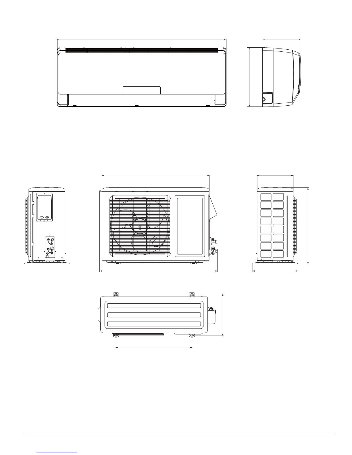
DIMENSIONS − INDOOR
Unit Size
9 K 30.3 (770) 11.1 (283) 7.9 (201) 18.7 (8.5)
12 K 30.3 (770) 11.1 (283) 7.9 (201) 19.8 (9.0)
18 K 34.0 (865) 12.0 (305) 8.5 (215) 26.4 (12)
24 K 39.7 (1008) 12.6 (319) 8.7 (221) 33.1 (15.0)
DIMENSIONS − OUTDOOR
W
In. (mm)
WD
H
A12377
H
In. (mm)
D
In. (mm)
Net Operating Weight
Lbs. (Kg)
Figure 2 - Indoor Unit Dimensions
30.0 (762)
10.1 (257)
Unit: IN. (mm)
33.4 (848)
11.7 (267)
21.3 (540)
Figure 3 - 9K and 12K 115V (Net Operating Weight: 75 lbs. / 34 kg)
21.3 (540)
12.6 (320)
A12531
421 08 9205 00 10

DIMENSIONS − OUTDOOR
10.8 (274)
25.9 (658)
21.7 (551)
Unit: IN. (mm)
28.0 (711)
18.5 (470)
11.8 (300)
Figure 4 - 12K 230V (Net Operating Weight: 63.8 lbs. / 30 kg)
12.5 (318)
Unit: IN. (mm)
A12532
11 421 08 9205 00
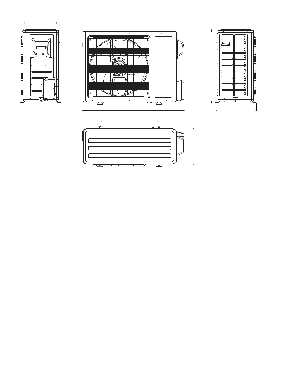
13.4 (340)
35.0 (890)
27.6 (700)
Unit: IN. (mm)
37.9 (963)
22.0 (560)
14.3 (364)
Figure 5 - 18K and 24K (Net Operating Weight: 112.2 lbs. / 51 kg)
15.6 (396)
A12533
421 08 9205 00 12
CLEARANCES
Indoor Unit
Distance to Ceiling
6 in (152 mm)
Distance to Wall
6 in (152 mm)
Distance in Front of Unit
118 in (2997 mm)
●
The clearance dimensions are necessary for a correct installation
Distance to Floor
66 in (1676 mm)
and are the minimum permissible distances to adjacent structures.
Outdoor Unit
Distance to Wall
6 in (152 mm)
NOTE: Refrigerant lines
may be routed in any of the
(4) directions, right,
right rear, left, or left rear.
See instructions for details
Distance to
Back Wall
12 in (305 mm)
Air Discharge Side
79 in (2007 mm)
Figure 6 - Indoor and Outdoor Unit Clearances
13 421 08 9205 00
Above Unit
20 in (508 mm)
Air Inlet Side
12 in (305 mm)
Distance to Wall
20 in (508 mm)
valve cover
A12385
SYSTEM OPERATING ENVELOPE
64.4ºF
75ºF
5ºF
113ºF
Heating
5ºF
75ºF
5ºF
86ºF
109ºF
Supply Voltage 115-1-60 AC 208/230-1-60 AC
Model 9k 12k 12k 18k 24k
Indoor Operating Range (A/C and
HP) °F (°C)
Cooling Ambient Operating Range
(A/C) °F (°C)
Cooling Ambient Operating Range
(HP) °F (°C)
Heating Ambient Operating Range
(HP) °F (°C)
64 - 113
(18 - 45)
64 - 113
(18 - 45)
5 - 75
(-15 - 24)
64 - 113
(18 - 45)
64 - 113
(18 - 45)
5 - 75
(-15 - 24)
See Figure 7 8 9 10 & 11
120
110
100
90
86ºF
80
Heating
Continuous
Indoor Temperature (°F)
70
Operation
61 - 86 (16 - 30)
5 - 109
(-15 - 43)
5 - 109
(-15 - 43)
5 - 75
(-15 - 24)
Cooling
Continuous
Operation
5 - 118
(-15 - 48)
5 - 118
(-15 - 48)
19 - 75
(-7 - 24)
86ºF
5 - 118
(-15 - 48)
5 - 115
(-15 - 46)
19 - 75
(-7 - 24)
61ºF
60
50
40
-10 0 10 20 30 40 50 60 70 80 90 100 110 120 130 140
Outdoor Temperature (°F)
61ºF
Figure 7 - 9k / 12k 115V System Operating Envelope
120
110
100
90
86ºF
Indoor Temperature (°F)
80
Continuous
70
61ºF
60
Operation
Cooling
Continuous
Operation
61ºF
50
40
-10 0 10 20 30 40 50 60 70 80 90 100 110 120 130 140
421 08 9205 00 14
Outdoor Temperature (°F)
Figure 8 - 12k 230V System Operating Envelope
SYSTEM OPERATING ENVELOPE CONTINUED
Heating
5ºF
75ºF
19ºF
86ºF
118ºF
Cooling
5ºF
118ºF
120
110
100
90
80
Continuous
Indoor Temperature (°F)
70
Operation
86ºF
Cooling
Continuous
Operation
61ºF
60
50
40
-10 0 10 20 30 40 50 60 70 80 90 100 110 120 130 140
Outdoor Temperature (°F)
61ºF
Figure 9 - 18k 230V System Operating Envelope
120
110
100
F)
°
90
86ºF
80
Continuous
70
Indoor Temperature (
60
Operation
61ºF
50
40
-10 0 10 20 30 40 50 60 70 80 90 100 110 120 130 140
Figure 10 - 24k AC 230V System Operating Envelope
15 421 08 9205 00
Outdoor Temperature (°F)
SYSTEM OPERATING ENVELOPE CONTINUED
Heating
50ºF
75ºF
5ºF
86ºF
118ºF
120
110
100
F)
°
90
80
70
Indoor Temperature (
Continuous
Operation
86ºF
Cooling
Continuous
Operation
61ºF
60
50
40
-10 0 10 20 30 40 50 60 70 80 90 100 110 120 130 140
Outdoor Temperature (°F)
61ºF
Figure 11 - 24k HP 230V System Operating Envelope
421 08 9205 00 16
ELECTRICAL DATA
Cooling Only
Operating
System Voltage
Unit
Size
9 K 115 -1 - 60 127/103 9.76 25.00 0.17 30
12 K 115 -1 - 60 127/103 11.20 25.00 0.17 30 15 25
12 K 208/230-1-60 253/187 7.30 16.50 0.25 21 208/230 0.19 15 10 15
18 K 208/230-1-60 253/187 10.86 27.00 0.62 60 208/230 0.32 20 15 25
24 K 208/230-1-60 253/187 11.71 41.00 0.62 60 208/230 0.45 35 16 25
Heat Pump
9 K 115-1-60 127/103 9.76 20.00 0.17 30
12 K 115-1-60 127/103 11.20 20.00 0.17 30 15 25
12 K 208/230-1-60 253/187 7.30 16.50 0.25 21 208/230 0.19 15 10 15
18 K 208/230-1-60 253/187 10.86 27.00 0.62 60 208/230 0.32 20 15 25
24 K 208/230-1-60 253/187 12.50 41.00 0.62 60 208/230 0.45 35 17 25
* Permissible limits of the voltage range at which the unit will operate satisfactorily
Indoor fan powered from outdoor unit.
LEGEND
FLA - Full Load Amps
LRA - Locked Rotor Amps
MCA - Minimum Circuit Amps
RLA - Rated Load Amps
MOCP- Maximum Over Current Protection
Voltage*
MAX /
MIN
Compressor Outdoor Fan Indoor Fan{
RLA LRA FLA W VOLTS FLA W
115 0.38 15
115 0.38 15
MCA
13 20
13 20
WIRING
Power Wiring:
The main power is supplied to the outdoor unit. The field supplied connecting cable from the outdoor unit to indoor unit consists of three
(3) wires and provides the power for the indoor unit. Two wires are high voltage AC power and one is a ground wire.
Consult your local building codes and the NEC (National Electrical Code) or CEC (Canadian Electrical Code) for special requirements.
All wires must be sized per NEC or CEC and local codes. Use Electrical Data table MCA (minimum circuit amps) and MOCP (maximum
over current protection) to correctly size the wires and the disconnect fuse or breakers respectively.
Per caution note, only copper conductors with a minimum 300 volt rating and 2/64−inch thick insulation must be used.
MAX
FUSE/
CB Amp
(MOCP)VOLT-PH-HZ
Control Wiring:
A separate shielded copper conductor only, with a minimum 300 volt rating and 2/64−inch thick insulation, must be used as the
communication wire from from the outdoor unit to the indoor unit.
To minimize voltage drop of the control wire, use the following wire size and maximum lengths shown in the chart below.
Wire Size
18 AWG 50 ft. (15 m)
16 AWG 50 ft (15) to 100 ft. (30 m)
!
CAUTION
EQUIPMENT DAMAGE HAZARD
Failure to follow this caution may result in equipment
damage or improper operation.
Wires should be sized based on NEC and local codes.
Use copper conductors only with a minimum 300 volt
rating and 2/64 inch thick insulation.
!
EQUIPMENT DAMAGE HAZARD
Failure to follow this caution may result in equipment
damage or improper operation.
Be sure to comply with local codes while running wire
from indoor unit to outdoor unit.
Every wire must be connected firmly. Loose wiring may
cause terminal to overheat or result in unit malfunction. A
Length
ft (m)
CAUTION
fire hazard may also exist. Therefore, be sure all wiring is
tightly connected.
No wire should be allowed to touch refrigerant tubing,
compressor or any moving parts.
Disconnecting means must be provided and shall be
located within sight and readily accessible from the air
conditioner.
Connecting cable with conduit shall be routed through
hole in the conduit panel.
17 421 08 9205 00
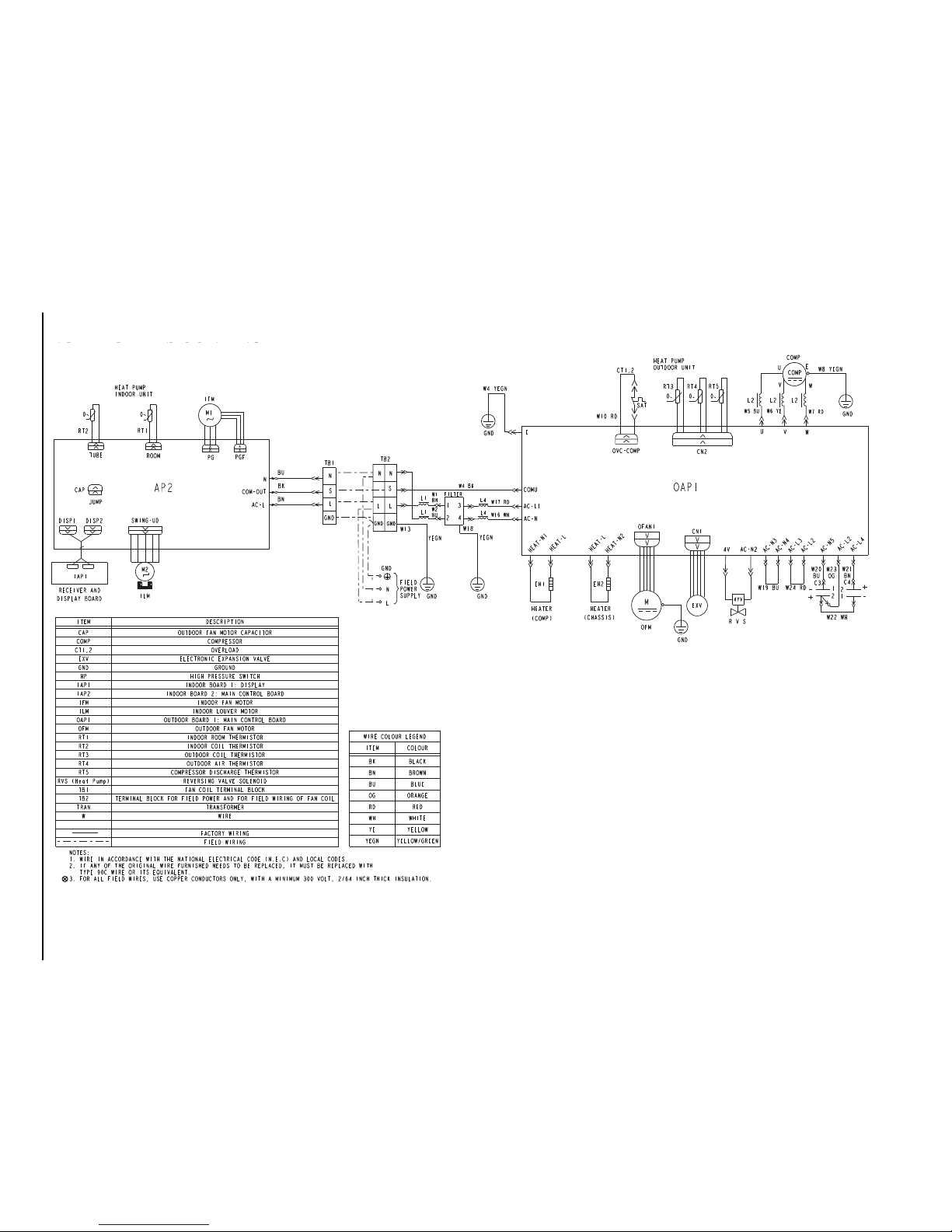
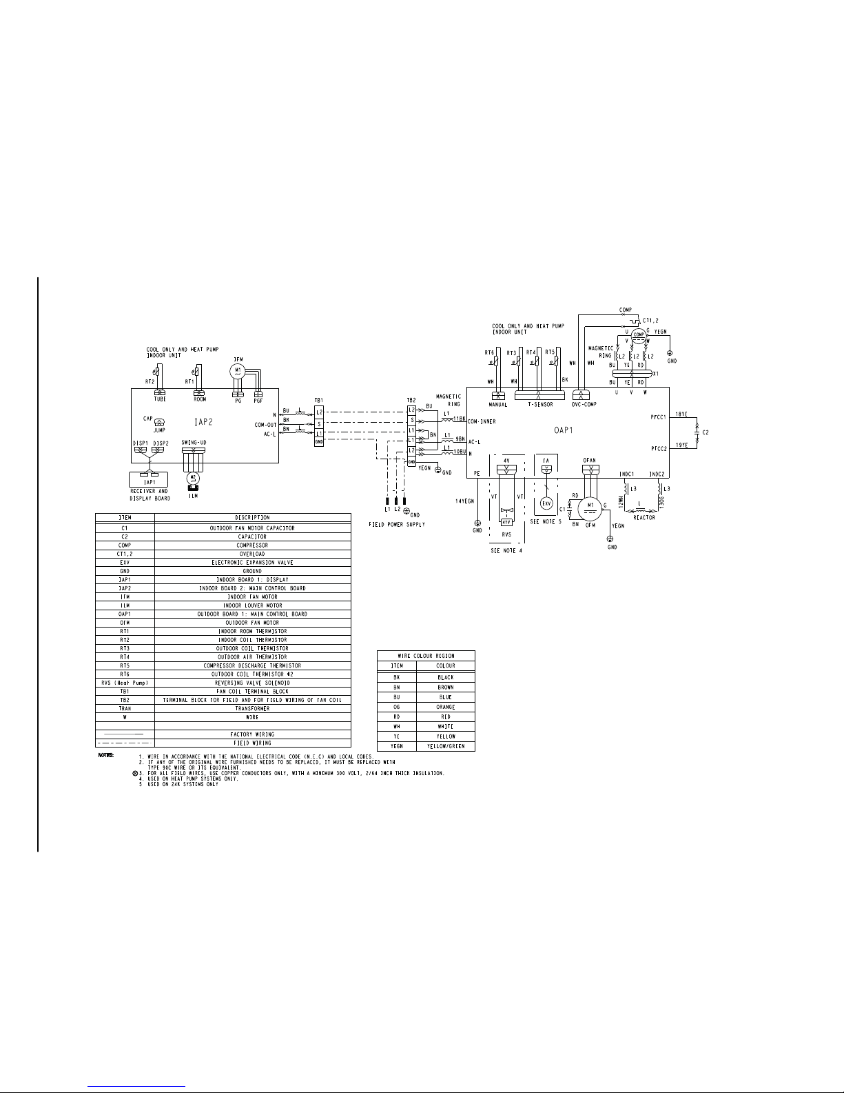
CONNECTION DIAGRAMS
DLC4 18K~24K Outdoor Unit Terminal Block
Control
from
Outdoor
Unit
DLF4 18K~24K Indoor Unit Terminal Block
DLC4/DLF4 18K~24K 208/230-1-60 Connection Diagram
CONNECTING CABLE
OUTDOOR TO INDOOR
Power from
Outdoor Unit
Power to
Indoor Unit
Main Power
Supply
Main Power
Supply
Power from
Outdoor Unit
Power to
Indoor Unit
Control to
Indoor Unit
CAUTION
Attention
Use Copper Conductors Only
With Minimum 300 Volt, 2/64"
Thick Insulation.
Utilisez seulement des
conducteurs en cuivre d'un
minimum de 300 volt d'une
isol at ion d' èpaisseur de 2/64".
Power from
Outdoor Unit
DLC4/DLF4 12K 208/230-1-60 Connection Diagram
Control to
Indoor Unit
Control from
Outdoor Unit
Power from
Outdoor Unit
CONNECTING CABLE
OUTDOOR TO INDOOR
Power to
Indoor Unit
Power to
Indoor Unit
Main Power
Supply
Main Power
Supply
DLC4 12K Outdoor Unit Terminal Block
DLF4 12K Indoor Unit Terminal Block
CAUTION
Attention
Use Copper Conductors Only
With Minimum 300 Volt, 2/64"
Thick Insulation.
Utilisez seulement des
conducteurs en cuivre d'un
minimum de 300 volt d'une
isolation d' èpaisseur de 2/64".
N S L GND N S L GND
NLGND
DLC4H6 9K-12K Heat Pump Outdoor Unit
Terminal Block
DLF4H6 9K-12K Heat Pump Indoor Unit
Terminal Block
Main Power
Supply
Main Power
Supply
DLC4H6/DLF4H6 9K-12K 115-1-60 Heat Pump Connection Diagram
CONNECTING CABLE
OUTDOOR TO INDOOR
Power to
Indoor Unit
Control to
Indoor Unit
Power to
Indoor Unit
Power from
Outdoor Unit
Control from
Outdoor Unit
Power from
Outdoor Unit
CAUTION
Attention
Use Copper Conductors Only
With Minimum 300 Volt, 2/64"
Thick Insulation.
Utilisez seulement des
conducteurs en cuivre d'un
minimum de 300 volt d'une
isol at ion d' èpaisseur de 2/64".
DLC4A6/DLF4A6 9K~12K 115-1-60 Cooling Only Connection Diagram
DLC4A6 9K~12K Outdoor Unit Terminal Block
CONNECTING CABLE
OUTDOOR TO INDOOR
Power to
Indoor Unit
Power to
Indoor Unit
Power from
Outdoor
Unit
Power from
Outdoor
Unit
Control to
Indoor Unit
Control
from
Outdoor
Unit
Main
Power
Supply
Main
Power
Supply
DLF4A6 9K~12K Indoor Unit Terminal Block
CAUTION
Attention
Use Copper Conductors Only
With Minimum 300 Volt, 2/64"
Thick Insulation.
Utilisez seulement des
conducteurs en cuivre d'un
minimum de 300 volt d'une
isol at ion d' èp aisseur de 2/64".
N S L L N GND N S L GND
Ground Ground
115-1-60 Low V DC 115-1-60 115-1-60 115-1-60 115-1-60 Low V DC 115-1-60
Ground Ground
115-1-60 Low V DC 115-1-60 115-1-60 Low V DC 115-1-60
Ground
115-1-60 115-1-60
L2 S L1 GND L2 S L1 GND
Ground Ground
208/230-1-60 Low V DC 208/230-1-60 208/230-1-60 Low V DC 208/230-1-60
L2 L1 GND
Ground
208/230-1-60 208/230-1-60
L2SL1L1L2GND L2SL1GND
Ground Ground
208/230-1-60 Low V DC 208/230-1-60 208/230-1-60 208/230-1-60 208/230-1-60 Low V DC 208/230-1-60
NOTE: Polarity of power wires muct match original connection on outdoor unit.
Figure 12 - Connection Diagrams
421 08 9205 00 18
A13080
19 421 08 9205 00
CONNECTION DIAGRAMS
WIRING DIAGRAMS
A13081
DLF4A609/12
DLC4A609/12
Figure 13 - 9K / 12K Cooling Only 115−1−60
20 421 08 9205 00
CONNECTION DIAGRAMS
A13082
DLF4H609/12J1
A
DLC4H609/12J1
A
Figure 14 - 9K / 12K Heat Pump Only 115−1−60
421 08 9205 00 21
CONNECTION DIAGRAMS
DIAGRAMS CONTINUED
A13083
DLF4H612K1
A
DLC4H612K1
A
Figure 15 - 12k Heat Pump Only 230−1−60
22 421 08 9205 00
CONNECTION DIAGRAMS
A13084
DLF4A618/24K1
A
DLC4A618/24K1
A
Figure 16 - 18K / 24K 230−1−60
REFRIGERATION SYSTEM DIAGRAMS
GAS SIDE
TINU ROODTUOTINU ROODNI
HEAT
EXCHANGE
(EVAPORATOR)
3-WAY VALVE
LIQUID SIDE
2-WAY VALVE
Muffler
Discharge
Suction
COMPRESSOR
Accumlator
HEAT
EXCHANGE
(CONDENSER)
Capillary
Figure 17 - Refrigeration System Diagram DLC/DLF4A6 Cooling Only
9k / 12k − 115v; 12k / 18k − 230v
TINU ROODTUOTINU ROODNI
reniartSreniartS
COOLING
A13086
GAS SIDE
3-WAY VALVE
HEAT
EXCHANGE
(EVAPORATOR)
LIQUID SIDE
2-WAY VALVE
Figure 18 - Refrigeration System Diagram DLC/DLF4H6
Refrigerant Pipe Diameter:
9k / 12k − Liquid: 1/4” (6.4 mm) Gas: 3/8” (9.5 mm)
18k − Liquid: 1/4” (6.4 mm) Gas: 1/2” (12.7 mm)
Discharge
Suction
COMPRESSOR
12k / 18k − 230v
4-Way valve
Muffler
Accumlator
HEAT
EXCHANGE
(CONDENSER)
Capillary reniartSreniartS
COOLING
HEATING
A13087
23 421 08 9205 00
REFRIGERATION SYSTEM DIAGRAMS CONTINUED
INDOOR OUTDOOR
GAS SIDE
HEAT
EXCHANGE
(EVAPORATOR)
3-WAY VALVE
LIQUID SIDE
2-WAY VALVE
Muffler
Discharge
Suction
COMPRESSOR
Accumlator
Electronic Expansion Valve
HEAT
EXCHANGE
(CONDENSER)
Strainer
Figure 19 - Refrigeration System Diagram DLC/DLF4A6 Cooling Only
24k − 230v
TINU ROODTUOTINU ROODNI
COOLING
A13088
GAS SIDE
HEAT
EXCHANGE
(EVAPORATOR)
3-WAY VALVE
LIQUID SIDE
2-WAY VALVE
Muffler
Discharge
Suction
COMPRESSOR
Accumlator
4-Way valve
Expansion valve
HEAT
EXCHANGE
(CONDENSER)
reniartSreniartS
COOLING
HEATING
Figure 20 - Refrigeration System Diagram DLC/DLF4H6
9k / 12k − 115v; 24k − 230v
Refrigerant Pipe Diameter:
9k / 12k − Liquid: 1/4” (6.4 mm) Gas: 3/8” (9.5 mm)
24k − Liquid: 1/4” (6.4 mm) Gas: 1/2” (12.7 mm)
24 421 08 9205 00
A13089
SYSTEM EVACUATION AND CHARGING
t
Deep Vacuum Method
!
UNIT DAMAGE HAZARD
Failure to follow this caution may result in equipment
damage or improper operation.
Never use the system compressor as a vacuum pump.
Refrigerant tubes and indoor coil should be evacuated using
the recommended deep vacuum method of 500 microns. The
alternate triple evacuation method may be used if the
procedure outlined below is followed. Always break a vacuum
with dry nitrogen.
SYSTEM VACUUM AND CHARGE
Using Vacuum Pump
(1.) Completely tighten flare nuts A, B, C, D, connect
manifold gage charge hose to a charge port of the
low side service valve. (See Fig. 21.)
(2.) Connect charge hose to vacuum pump.
(3.) Fully open the low side of manifold gage. (See Fig.
22)
(4.) Start vacuum pump
(5.) Evacuate using either deep vacuum or triple
evacuation method.
(6.) After evacuation is complete, fully close the low side
of manifold gage and stop operation of vacuum
pump.
(7.) The factory charge contained in the outdoor unit is
good for up to 25 ft. (8 m) of line length. For
refrigerant lines longer than 25 ft (8 m), add 0.1 oz.
per foot of extra piping up to allowable maximum
length listed in physical data.
(8.) Disconnect charge hose from charge connection of
the low side service valve.
(9.) Fully open service valves B and A.
(10.) Securely tighten caps of service valves.
Outdoor Unit
Service Valve
CAUTION
Refrigerant
Low Side
A
High Side
B
Figure 21 - Service Valve
The deep vacuum method requires a vacuum pump capable
of pulling a vacuum of 500 microns and a vacuum gage
capable of accurately measuring this vacuum depth. The
deep vacuum method is the most positive way of assuring a
system is free of air and liquid water. (See Fig. 23)
Triple Evacuation Method
The triple evacuation method should only be used when
vacuum pump is only capable of pumping down to 28 in. of
mercury vacuum and system does not contain any liquid
water.
Refer to Fig. 24 and proceed as follows:
Indoor Uni
C
D
A07360
5000
4500
4000
3500
3000
2500
2000
MICRONS
1500
1000
500
01234567
MINUTES
LEAK IN
SYSTEM
VACUUM TIGHT
TOO WET
TIGHT
DRY SYSTEM
A95424
Figure 23 - Deep Vacuum Graph
(1.) Pump system down to 28 in. of mercury and allow
pump to continue operating for an additional 15
minutes.
(2.) Close service valves and shut off vacuum pump.
(3.) Connect a nitrogen cylinder and regulator to system
and open until system pressure is 2 psig.
(4.) Close service valve and allow system to stand for 1
hr. During this time, dry nitrogen will be able to diffuse
throughout the system absorbing moisture.
(5.) Repeat this procedure as indicated in Fig. 24. System
will then be free of any contaminants and water
vapor.
EVACUATE
BREAK VACUUM WITH DRY NITROGEN
WAIT
EVACUATE
BREAK VACUUM WITH DRY NITROGEN
Manifold Gage
500 microns
Low side valve
Charge hose
Low side valve
High side valve
Charge hose
Figure 22 - Manifold
421 08 9205 00 25
Vacuum pump
A07361
WAIT
EVACUATE
CHECK FOR TIGHT, DRY SYSTEM
(IF IT HOLDS DEEP VACUUM)
RELEASE CHARGE INTO SYSTEM
A95425
Figure 24 - Triple Evacuation Method
Final Tubing Check
IMPORTANT: Check to be certain factory tubing on both
indoor and outdoor unit has not shifted during shipment.
Ensure tubes are not rubbing against each other or any
sheet metal. Pay close attention to feeder tubes, making
sure wire ties on feeder tubes are secure and tight.
REMOTE CONTROL AND FUNCTIONS
ON/OFF
(1)
Press to start or stop operation
AUTO
FAN
AIR
HEALTH
OPER
X-FAN
HUMIDITY
FILTER
TURBO
(1) (2)
(3)
(5)
ON/OFF
FAN
HOUR
ON/OFF
MODE
(4)
(6)
(2) MODE
Press to select operation mode
(AUTO/COOL/DRY/FAN/HEAT)
(3) - : Press to decrease temperature setting
(4) +: Press to increase temperature setting
(5) FAN
Press to set fan speed
(6) Horizontal Swing
Press to activate horizontal swing or set louver positions
(7) HEALTH|SAVE (Not Available)
(8) Vertical Swing (Not Available)
(9) X-FAN
Press to activate or deactivate DRY function
(10) TEMP
Press to alternate between set point and room temperature display
(11) TIMER
Press to set TIMER ON/ TIMER OFF
(12) TURBO
Press to activate or deactivate TURBO mode
(13) SLEEP
Press to activate or deactivate SLEEP mode
(14) LIGHT
Press to activate or deactivate display panel light
(7)
(9)
(12)
X-FAN
TURBO
(10)
(13)
TEMP
SLEEP
TIMER
LIGHT
(8)
(11)
(14)
A12390
Remote Control
26 421 08 9205 00
Remote Control Display
3
1
MODE DISPLAY
AUTO
COOL
DRY
FAN
HEAT
8
4
10
15
2
11
6
9
5
SLEEP
14 1312
7
A12391
NOTE: Symbols shown in this manual are for the purpose of demonstration. During actual operation, only the
relevant symbols are displayed.
1. TRANSMISSION INDICATOR: Illuminates when re-
mote control transmits signals to the indoor unit.
2. This symbol appears when the unit is turned on by
the remote control, and disappears when the unit is
turned off.
3. FAN SPEED DISPLAY: Indicates the set fan speed.
AUTO is displayed when unit is running in AUTO
mode.
4. MODE DISPLAY: Indicates the current operation
mode “AUTO”, “COOL”, “DRY”, “FAN ONLY”, or
“HEAT”
5. SLEEP DISPLAY: Indicates unit is running in SLEEP
mode.
6. TEMPERATURE DISPLAY: Temperature setting
from 61F (16C) to 86F (30C) will be displayed.
If FAN mode is selected, there will be no temperature
displayed. During DEFROST operation, H1 will be
displayed. During SAVE mode, SE will be displayed.
7. Left/Right Louver Swing: Not available on these
models.
8. HEALTH/SAVE: HEALTH is not available. SAVE is
available on sizes 18k and 24k. SAVE mode can be
applied to cooling mode and when set point is less
than 80F (27C).
9. SETTING ON / OFF TIMES: 0.5 to 24 hours.
10. TURBO DISPLAY: Displayed when unit is running in
TURBO mode.
11. DRY COIL DISPLAY: Indicates unit is running in DRY
COIL mode where the fan continues to run after the
unit is shut off to dry the coil.
12. TEMPERATURE DISPLAY: Displays set point or
room temperature.
13. SWING DISPLAY: Sets louver position or set louvers
to continuously move for better air distribution.
14. LIGHT DISPLAY: Indicates if LED display on the front
panel is illuminated or not.
15. LOCK DISPLAY: Indicates if remote control is locked.
Battery Installation
Two AAA 1.5 v alkaline batteries (included) are required for
operation of the remote control.
To install or replace batteries :
1. Slide the back cover off the control to open the battery
compartment.
2. Remove old batteries if you are replacing the batteries.
3. Insert batteries. Follow the polarity markings inside
the battery compartment.
4. Replace battery compartment cover.
A08299
NOTE:
1. When replacing batteries, do not use old batteries or a
different type battery. This may cause the remote control to
malfunction. 2.If the remote is not going to be used for
several weeks, remove the batteries. Otherwise battery
leakage may damage the remote control.
3. The average battery life under normal use is about 6
months.
4. Replace the batteries when there is no audible beep from
the indoor unit or if the Transmission Indicator fails to light.
421 08 9205 00 27
FUNCTION AND CONTROLS
Description of Each Control Operation
Temperature Parameters
Indoor preset temperature (T
Indoor ambient temperature (T
Basic Functions
Once energized, in no case should the compressor be
restarted within less than 3 minutes. In the situation that
memory function is available, for the first energization, if the
compressor is at stop before de−energization, the compressor
will be started without a 3−minute lag; if the compressor is in
operation before de−energization, the compressor will be
started with a 3−minute lag; and once started, the compressor
will not be stopped within 6 minutes regardless of changes in
room temperature;
Cooling Mode
Working Conditions and Cooling Process.
When T
amb . Tpreset, the unit will enter cooling operation, in
which case the indoor fan, the outdoor fan and the
compressor will work and the indoor fan will run at preset
speed.
When Tamb v Tpreset −3.6F , the compressor will stop, the
outdoor fan will stop with a time lag of 30 seconds (60
seconds for 30k and 36k units), and the indoor fan will run at
preset speed.
When T
preset −3.6F < Tamb. < Tpreset +1.8F, the unit will
remain at its previous state.
Under this mode, the four−way valve will be de−energized
and temperature can be set within a range from 61F to 86F.
If the compressor is shut down for some reason, the indoor
fan and the swing device will operate at original state.
Figure 25 - Cooling Mode
PROTECTION
Antifreeze Protection
Under cooling and dehumidifying mode, 6 minutes after the
compressor is started:
If Tevap v35.6°F, the compressor will operate at reduced
frequency.
If Tevap v30.2°F is detected for duration of 3 minutes, the
compressor will stop, and after 60 seconds, the outdoor fan
will stop; and under cooling mode, the indoor fan and the
swing motor will remain at the original state.
evap. 42.8°F and the compressor has remained at OFF for
If T
at least 3 minutes, the compressor will resume its original
operation state.
preset)
amb.)
Total current up and frequency down protection
If Itotal vA, frequency rise will be allowed; if Itotal ≥ B,
frequency rise will not be allowed; if I
will run at reduced frequency; and if I
total ≥ C, the compressor
total ≥ D, the compressor
will stop and the outdoor fan will stop with a time lag of 30s.
Lag will be 60s for size 30 and 36 units.
Total Current Table
Unit Size - V
9k115V 10A 12A 14A 16A
12K115V 14A 16A 18A 20A
12K230V 6A 7A 8A 9A
18k230V 8A 9A 10A 11A
24K230V 10A 11A 12A 13A
A B C D
Variables
Heating Mode
Working Conditions and Heating Process
amb. v Tpreset +3.6°F , the unit enters heating mode, in
If T
which case the four−way valve, the compressor and the
outdoor fan will operate simultaneously, and the indoor fan will
run at preset speed in the condition of preset cold air
prevention.
amb. ≥ Tpreset +9°F , the compressor will stop, the outdoor
If T
fan will stop with a time lag of 60s, and the indoor fan will stop
after 60−second blow at low speed
preset +3.6°F < Tamb. < Tpreset +9°F , the unit will maintain
If T
its original operating status.
Under this mode, the four−way valve is energized and
temperature can be set within a range of 61°F − 86°F. The
operating symbol, the heating symbol and preset temperature
are revealed on the display.
Defrost Mode
Condition and Defrost Process
When Toutdoor amb
hour, if Toutdoor tube
. ≥41°F and the compressor has run for 3
< 0°F is continuously detected for 1
minute, the unit will enter defrost. [Note: the accumulated time
is cleared if one of the below condition is met. Toutdoor ambient >
41°F, the compressor starts up after switching to cooling or
dry mode, when defrosting is finished; for other situations
besides above conditions, the accumulated time will not be
cleared (including the unit stops when reaching the
temperature point, the unit stops for protection, switching to
fan mode, et. )]
When duration of successive heating operations is more than
45 minutes, or accumulated heating time IS more than 90
minutes,
and one of the following conditions is reached, the unit will
enter the defrost mode after 3 minutes.
Toutdoor amb. >41°F, Toutdoor tube v28.4°F
a.
b. 28.4°F vToutdoor amb. <41°F, Toutdoor tube v21.2°F
c. 23°F
vToutdoor amb. <28.4°F, Toutdoor tube v17.6°F
d. 14°FvTouter amb. <23°F, Touter tube − Tcompensatorys
v(Toutdoor amb. −5.4°F)
Toutdoor amb.>14°F Touter tube − Tcompensatorys v(Toutdoor amb.
e.
−
5.4°F)
After energization, for the first defrost, T
is not the first defrost, Tcompensation will be determined by
outdoor pipe when defrost ends.
T
outdoor pipe >35.6°F; Tcompensation = 0°F
a. T
b. Toutdoor pipe v35.6°F; Tcompensation = 5.4°F
compensation = 0°F. If it
28 421 08 9205 00

During defrost, if operation time for compressor doesn’t reach
3 minutes, the condenser will not defrost in the next 2 hours.
At the time of defrost the compressor stops operation, and 30
seconds later, the outdoor fan stops operation. In an
additional 30 seconds, the 4−way valve will stop operation. 30
seconds later, compressor will increase it’s frequency to 85
Hz for defrosting. Defrost will last for 450 seconds, or until the
outdoor pipe ≥ 50°F. When defrost is complete the
compressor will decrease its frequency. 30 seconds later the
compressor will stop operation. In 30 seconds the 4−way
valve will be started up. 60 seconds later the compressor and
outdoor fan will operate.
PROTECTION
Cold air prevention
The unit is started under heating mode (the compressor is
ON):
In the case of T
indoor amb. <75.2°F : if Ttube v107.6°F and
the indoor fan is stopped, the indoor fan will begin to run at
low speed with a time lag of 2 minutes. Within 2 minutes, if
T
tube >104°F, the indoor fan also will run at low speed; and
after 1−minute operation at low speed, the indoor fan will be
ramped to operation at a preset speed. Within 1−minute of low
speed operation or 2−minutes of non−operation, if
tube>108°F, the fan will run at preset speed.
T
In the case of Ti
ndoor amb. ≥ 75°F: if Ttube v108°F, the
indoor fan will run at low speed, and after one minute, the
indoor fan will be ramped to preset speed. Within one−minute
low speed operation, if T tube>107.6°F, the indoor fan will be
ramped to preset speed.
Note: T
indoor amb. indicated in and refers to, the
indoor ambient temperature before the command to start the
compressor is performed, or after the unit is withdrawn from
defrost and the defrost symbol is cleared.
Total current up and frequency down protection
If the total current I
I
total ≥X frequency rise will not be allowed; if Itotal ≥Y, the
compressor will run at reduced frequency; and if I
total ≤W, frequency rise will be allowed; if
total ≥Z, the
compressor will stop and the outdoor fan will stop with a time
lag of 30s.
Fan Mode
Under the mode, the indoor fan will run at preset speed and
the compressor, the outdoor fan, the four−way valve and the
electric heater will stop.
Under the mode, temperature can be set within a range of
61°F − 86°F.
AUTO Mode
Working conditions and Auto mode process:
Under AUTO mode, standard cooling temperature T
77°F and standard heating temperature T
Once energized, if T
heating mode; if 68°F < T
amb ≤68°F, the unit will be started under
amb.< 77°F, the unit will run under fan
preset is 64.4°F.
mode and the run indicator will be bright; and if T
preset is
amb ≥77°F,
the unit will be started under cooling mode.
Under AUTO mode, if T
amb.wTpreset is detected, the unit will
select to run under cooling mode, in which case the preset
temperature is 77°F; if T
amb.vTpreset −3.6°F, the compressor
will stop, the outdoor fan will stop with a time lag of 1 minute,
and the indoor fan will run at preset speed. If T
preset
–(−3.6°F)< Tamb.< Tpreset , the unit will remain in its original
state.
Under AUTO mode, if Tamb. vTpreset +3.6°F is detected, the
unit will select to run under heating mode, in which case the
preset temperature is 64.4°F; if T
amb.wTpreset +9°F, the
compressor will stop, the outdoor fan will stop with a time lag
of 1 minute, and the indoor fan will blow residual heat; and if
T
preset +3.6°F < Tamb. < Tpreset +9°F, the unit will remain in its
original state. The cooling−only unit will run under fan mode.
Under AUTO mode, if 68°F
< Tamb. < 77°F, the unit will
remain in its original state.
Protection
In cooling operation, protection is the same as that under the
cooling mode.
In heating operation, protection is the same as that under the
heating mode.
When ambient temperature changes, operation mode will be
converted preferentially. Once started, the compressor will
remain unchanged for at least 6 minutes.
Common Protection Functions and Fault Display under
COOL, HEAT, DRY and AUTO Modes
Overload protection
T tube : measured temperature of outdoor heat exchanger
under cooling mode; and measured temperature of indoor
heat
exchanger under heating mode.
1) Cooling overload
tube v 125.6°F, the unit will return to its original
a. If T
operation state.
b. If T tube w 131°F, frequency rise is not allowed.
c. If T tube w136.4°F, the compressor will run at reduced
frequency.
d. If T
tubew143.6°F, the compressor will stop and the indoor
fan will run at preset speed.
2) Heating overload
a. If T
tubev125.6°F, the unit will return to its original operation
state.
b. If T
tube w131°F, frequency rise is not allowed.
c. If T tube w136.4°F, the compressor will run at reduced
frequency.
d. If
T tubew143.6°F, the compressor will stop and the indoor
fan will blow residual heat and then stop.
Exhaust temperature protection of compressor
If exhaust temperature
w208.4°F, frequency is not allowed to
rise.
If exhaust temperature
w217.4°F, the compressor will run at
reduced frequency.
If exhaust temperature
If exhaust temperature
w230°F, the compressor will stop.
w194°F and the compressor has
stayed at stop for at least 3 minutes, the compressor will
resume its operation.
Communication fault
If the unit fails to receive correct signals for 3 minutes, a
communication fault will be registered and the whole system
will stop.
Module protection
Under module protection mode, the compressor will stop.
When the compressor remains at a stop for at least 3 minutes,
the compressor will resume its operation. If module protection
occurs six times in succession, the compressor will not be
started again.
421 08 9205 00 29
Overload protection
If temperature sensed by the overload sensor is over 239°F,
the compressor will stop and the outdoor fan will stop with a
time lag of 30 seconds. If the temperature drops below 203°F,
the overload protection will be reset.
If voltage on the DC bus is below 150V or over 420V, the
compressor will stop and the outdoor fan will stop with a time
lag of 30 seconds. When voltage on the DC bus returns to its
normal value and the compressor has stayed at a stop for at
least 3 minutes, the compressor will resume its operation.
Faults of temperature sensors
Description of Sensors Faults
Indoor Ambient
Temperature
Indoor Tube Temperature
Outdoor Ambient
Temperature
Outdoor Tube
Temperature
Exhaust
Overload
The sensor is open or short-circuited for 30
consecutive seconds
The sensor is open or short-circuited for 30
consecutive seconds
The sensor is open or short-circuited for 30
consecutive seconds
The sensor is open or short-circuited for 30
consecutive seconds, and no detection is
performed within 10 minutes after defrost begins
After the compressor has run for 3 minutes, the
sensor is open or short-circuited for 30
consecutive seconds
After the compressor has run for 3 minutes, the
sensor is open or short-circuited for 30
consecutive seconds
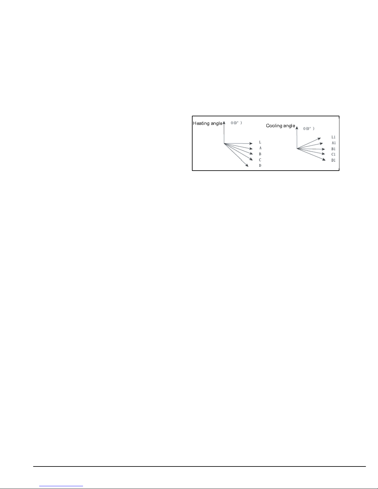
(9) Up−and−Down Swinging Control
When the power is turned on, the up−and−down motor will
first move the air deflector to 0 counter−clockwise. The air
outlet will be closed.
After starting the machine, if you don’t set the swinging
function, heating mode and auto−heating mode, the
up−and−down air deflector will move to D clockwise; under
other modes, the up−and−down air deflector will move to L1. If
you set the swing function when you start the machine, then
the deflector will swing between L and D. The air deflector has
7 swing states: Location L, Location A, Location B, Location
C, Location D, Location L to Location D, stop at any location
between L−D (the included angle between L~D is the same).
The air deflector will be closed at 0 location, and the swing is
function only works if the indoor fan is running.
Figure 26 - Swing Angles for Heating and Cooling
NOTE: Refer to Appendix Tables on pages 60-62 for sensor information.
Other Controls
(1) ON/OFF
Press the remote button ON/OFF: the on−off state will be
changed once each time you press the button.
(2) Mode Selection:
Press the remote button MODE, then select: AUTO, COOL,
DRY, FAN, HEAT, or AUTO.
(3) Temperature Setting Option Button
Each time you press the remote button TEMP+ or TEMP−, the
setting temperature will be up or down by 1°F. Regulating
Range: 61−86°F , the button is useless under the AUTO
mode.
(4) Time Switch
You can start and stop the machine according to the setting
time with the remote controller.
(5) SLEEP State Control
a. When the indoor unit is in the COOL or DRY mode, and the
SLEEP mode has been set, after about 1 hour, the
pre−setting T will raise 1.8°F. It will raise another 1.8°F again
after 2 hours. It will raise 3.6°F in 2 hours, then it will run on at
the setting temperature and fan speed.
b. When the indoor unit is in the HEAT mode, and the Timer
has been set, after about 1 hour, the pre−setting T will reduce
1.8°F, and it will reduce another 1.8°F again after 2 hours. It
will reduce 3.6°F in 2 hours, then it will run on at the setting
temperature and blower speed.
c. The set point stays the same under the FAN mode and
AUTO mode.
(6) Indoor Fan Control
The Indoor Fan can be set to HIGH, MED, LOW by remote
control, and the Indoor Fan will be respectively run at high,
medium, low speed. It can also be set as AUTO.
In moisture removal mode, the Indoor Fan will be set to low
speed.
(7) Buzzer Control
The buzzer will send a “Beep” sound when the indoor unit is
powered up or receives the information sent by the remote
control or there is a button pushed.
(8) Auto button
If the controller is on, it will stop when the button is pressed. If
the controller is off, it will start when the button is pressed. The
swing light will be on, and the main unit will run based on the
remote controls current settings.
(10) Display
a. Operation pattern and mode pattern display
All the display patterns will display for a time when the unit is
powered on, the operation indication icon will display in red
under standby status. When the machine is started by remote
controller, the indication icon will light and display the current
operation mode (the mode light includes: Cooling, Heating
and Dry). If you press the light button, all the display icons will
go dark.
b. Double−8 display
According to the settings of the remote control, the display
may show the current temperature (the temperature scope is
from 61°F to 86°F) on the indoor ambient temperature. The
heating and air supply temperature will display 77°F under
auto−mode, the temperature will display 64°F under the
heating mode, and the temperature will display H1 under the
defrosting mode.(If you set the Celsius temperature display,
the display will show according to Celsius temperature)
(11) Protection function and failure display
E2: Freeze−proofing E4: Exhaust protection E5: Over−current
protection
E6: Communication failure E8: Overload protection
F1: Indoor ambient sensor start and short circuit (continuously
measured failure for 30S)
F2: Indoor evaporator sensor start and short circuit
(continuously measured failure for 30S)
F3: Outdoor ambient sensor start and short circuit
(continuously measured failure for 30S)
F2: Outdoor condenser sensor start and short circuit
(continuously measured failure for 30S, and not measured
within 10 minutes after defrosted)
F5: Outdoor exhaust sensor start and short circuit
(continuously measured failure for 30S after the compressor
has operated 3 minutes)
H3: Overload protection of compressor H5: Module protection
PH: High−voltage protection PL: Low−voltage protection
P1: Nominal cooling and heating P2: Maximum cooling and
heating
P3: Medium cooling and heating P0: Minimum cooling and
heating
(12) Drying Function
You may start or stop the dry function under the cooling and
dry modes. Automatic heating and air modes do not support
the dry function).
30 421 08 9205 00

(13) Memory function when interrupting the power supply
Memory content: mode, swing function, light, set temperature
and blower speed.
After power is interrupted, the machine will start according to
the content of the memory automatically. If the last remote
control command has not set a timed function, the system will
remember the last remote control command and operate
accordingly. If the last remote control command has set a
timed function and the power supply is interrupted before the
time expires, the system will remember the timed function of
the last remote control command, the timed time will be
recounted from power on. If the last remote control command
has set a timed function, the time is up and the system is
started or stopped according to the set time when the power
supply is interrupted, the system will remember the operation
status before the power supply was interrupted, and not carry
out the timed action; The time clock will not be remembered.
Detection of Temperature Sensor Malfunction
Indoor Temperature Sensor
Malfunctions of the temperature sensor can be detected at
any time.
Indoor Pipe Temperature Sensor
During defrost, a temperature sensor malfunction will not be
detected. Five minutes after finishing defrost, the system will
again begin to detect temperature sensor malfunctions. At all
other times, a temperature sensor malfunction will be detected
when:
1. A short−circuit occurs to the temperature sensor for 30
seconds: The temperature sensor overheats. In this case to
protect the system, the entire unit will stop. At the same time,
the temperature protection and temperature sensor
malfunction will be shown.
2. An open circuit of the temperature sensor occurs for 30s:
The unit will stop and the temperature sensor malfunction will
be displayed
Frequency Control
When starting the compressor, or when conditions have
varied due to the changes in the room, the frequency must be
initialized according to the DD value of the indoor unit and the
Q value of the indoor unit. Q value: Indoor unit output
determined from indoor unit volume, air flow rate and other
factors.
Compressor Protection Function
When turning the compressor from OFF to ON, the system
will ramp the frequency up from a lower starting limit to protect
the compressor.
Figure 27 - Compressor Frequency (When the
compressor is turned off, it cannot be turned back on for
3 minutes, except after defrost.
Discharge Pipe Control
The discharge pipe temperature is used as the compressor’s
internal temperature. If the discharge pipe temperature rises
above a certain level, the operating frequency upper limit is
set to keep this temperature from going up further.
Input Current Control
Detects an input current with the current transformer as the
compressor is running, and sets the upper frequency limit
from the input current.
In the case of a heat pump, this control is the upper limit
control function of the frequency, which takes priority over the
lower limit of four way valves activation compensation.
Freeze−up Protection Control
During cooling operation, the signals being sent from the
indoor unit allow operating frequency limitation and then
prevent freezing of the indoor heat exchanger.
Heating Peak−cut Control: Heat−Pump Only
During heating operation, the signals being sent from the
indoor unit allow operating frequency limitation and prevent
abnormally high pressure.
Defrost Control: Heat Pump Only
Defrosting is carried out by the cooling cycle (reverse cycle).
The defrost time must be complete or the outdoor heat
exchanger temperature must be more than its preset value
when finishing.
Conditions for Starting Defrost
The starting conditions must be determined by the outdoor air
temperature and heat exchanger temperature. When the
system is in heating operation, 6 minutes after the
compressor is started, and more than 44 minutes of
accumulated time has passed since the start of the operation
or end of defrost.
Conditions for Canceling Defrost
The heat exchanger temperature must be between
(39°F−72°F)
Fan Control
Fan control is carried out according to the following
priority.
1. Fan ON control for electric component cooling fan
2. Fan control when defrosting
3. Fan OFF delay when stopped
4. ON/OFF control in cooling operation
5. Speed control when frequency adjustment function is
working
6. Fan control in forced operation
7. Fan control in indoor/outdoor unit silent operation
8. Fan control in powerful mode
9. Fan control in normal operation
Fan OFF Control when Stopped
Fan OFF delay for 60 seconds must be made when the
compressor is stopped.
Speed Control in indoor/outdoor unit silent operation
1. When in Cooling Operation
When the outdoor air temperature is lower than 99°F, the
speed tap must be set to Low.
2. When in Heating Operation
When the outdoor air temperature is higher than 39°F, the
speed tap must be set to Low (only for heat pump model).
421 08 9205 00 31

TROUBLESHOOTING
Precautions for Performing Inspections and Repairs
Be cautious during installation and maintenance. Follow all
rules and regulations to avoid electric shock and to prevent
injury or damage.
!
ELECTRICAL SHOCK HAZARD
Failure to follow this warning could result in personal
injury or death.
Before installing, modifying, or servicing system, main
electrical disconnect switch must be in the OFF position.
There may be more than one disconnect switch. Lock out
and tag switch with a suitable warning label.
Static Maintenance
Static Maintenance is maintenance during de−energization of
the indoor unit.
For static maintenance, make sure that the unit is
de−energized and the plug is disconnected.
Dynamic Maintenance
Dynamic maintenance is the maintenance during energization
of the unit.
Before dynamic maintenance, check the electricity and
ensure that there is a good ground. Check if there is electricity
on the case and copper pipe of the indoor unit with a voltage
tester.
WARNING
!
ELECTRICAL SHOCK HAZARD
Failure to follow this warning could result in personal
injury or death.
A large−capacity electrolytic capacitor is used in the
outdoor unit controller (inverter). When the power supply
is turned off, charge (charging voltage DC280V to 380V)
remains and takes a long time to discharge.
Do Not open the outdoor unit for 20 minutes after power
has been turned OFF.
Take sufficient care to avoid directly touching any of the circuit
parts without first turning off the power.
At times, such as when the circuit board is to be replaced,
place the circuit board assembly in a vertical position.
Diagnose troubles according to the trouble diagnosis
procedure as described below.
Also refer to the check points in servicing written on the wiring
diagrams attached to the indoor/outdoor units.
No. Trouble Shooting Procedure
1 Confirmation
2 Code displays interpretation of error codes.
3 Basic System Check
WARNING
Confirmation:
1. Confirmation of Power Supply: Confirm that the
power breaker operates normally and provides power
2. Confirmation Voltage: Confirm that voltage is AC
220−240 ±10%. If voltage is not in this range, the unit
may not operate normally.
32 421 08 9205 00

TROUBLESHOOTING (CONTINUED)
Display and Interpretation of Error Codes:
This unit has on−board diagnostics. Error codes will appear on the LED display on the front panel of the indoor unit in place of
the temperature display. Error codes are also displayed on the outdoor unit microprocessor board with colored LED lights. The
table below explains the error codes for both units.
Diagnostic Codes
DLC/DLF4(A,H)6 9k / 12k, 115v
Malfunction
Indoor PCB Malfunction EE Replace indoor main board
Anti-freeze Protection E2 Outdoor ambient temperature is too low
System overload protection H4 Check for dirty or blocked heat exchangers
Indoor motor malfunction H6 Check motor mounting and wiring
Indoor pipe temperature sensor malfunction F2 Measure the resistance value in the sensor
Return air temperature sensor malfunction F1 Measure the resistance value in the sensor
Indoor board malfunction UF Replace indoor main board
Compressor overload protection H3 Check overload wiring
Compressor start-up failure Lc
Outdoor fan motor failure UH Check outdoor motor
Low voltage protection E5 Check incoming power
4-way valve malfunction U7 Replace 4-way valve
Compressor phase detection error U1 Replace outdoor main board
Compressor speed reduction H7
Current detection malfunction U5 Replace outdoor main board
Outdoor ambient temperature sensor
malfunction
Discharge temperature sensor malfunction
(out of range)
Discharge temperature sensor malfunction
(open or shorted)
Condenser temperature sensor malfunction
(open or shorted)
Heat sink over-temperature P8
DC over-current UU --
Heat sink temperature sensor malfunction P7 Replace outdoor main board
Low charge F0 Check for leaks
DC input voltage is too high PH Check incoming power supply
DC input voltage is too low PL Check incoming power supply
Communication malfunction E6 Check wiring connection
Indoor and outdoor unit mismatched UA Check system combination
Remarks:
Error Code
on indoor unit
Check if the resistance of the compressor and the resistance to
ground is normal. If the resistance is normal, the outdoor main
board may be defective.
Check if the resistance of the compressor and the resistance to
ground is normal. If the resistance is normal, the outdoor main
board may be defective.
F3 Measure the resistance value in the sensor
E4 Measure the resistance value in the sensor
F5 Measure the resistance value in the sensor
F4 Measure the resistance value in the sensor
Is outdoor ambient temperature out of system operating range?
Is heat sink blocked or damaged?
4 minutes after the compressor has stopped due to a protection error, an error code will
be displayed. To display other errors, press the LIGHT button six (6) times within four (4)
seconds.
NOTE: Refer to Appendix Tables on pages 60-62 for sensor information.
Repair Method/Cause
421 08 9205 00 33

TROUBLESHOOTING (CONTINUED)
Diagnostic Codes
DLC/DLF4(A,H)6 12K, 230v
Malfunction
Indoor PCB Malfunction EE Replace indoor main board
Anti-freeze Protection E2 Outdoor ambient temperature is too low
System overload protection H4 Check for dirty or blocked heat exchangers
Indoor motor malfunction H6 Check motor mounting and wiring
Indoor pipe temperature sensor malfunction F2 Measure the resistance value in the sensor
Return air temperature sensor malfunction F1 Measure the resistance value in the sensor
Indoor board malfunction UF Replace indoor main board
Compressor overload protection H3 Check overload wiring
Compressor start-up failure Lc
Outdoor fan motor failure UH Check outdoor motor
Low voltage protection E5 Check incoming power
4-way valve malfunction U7 Replace 4-way valve
Compressor phase detection error U1 Replace outdoor main board
Compressor speed reduction H7
Current detection malfunction U5 Replace outdoor main board
Outdoor ambient temperature sensor mal
function
Discharge temperature sensor malfunction
(out of range)
Discharge temperature sensor malfunction
(open or shorted)
Condenser temperature sensor malfunction
(open or shorted)
Heat sink over temperature P8
DC over-current H5 --
Heat sink temperature sensor malfunction P7 Replace outdoor main board
Low charge F0 Check for leaks
DC input voltage is too high PH Check incoming power supply
DC input voltage is too low PL Check incoming power supply
Communication malfunction E6 Check wiring connection
Indoor and outdoor unit mismatched UA Check system combination
Error Code on in
door unit
Check if the resistance of the compressor and the resistance to
ground is normal. If the resistance is normal, the outdoor main
board may be defective.
Check if the resistance of the compressor and the resistance to
ground is normal. If the resistance is normal, the outdoor main
board may be defective.
F3 Measure the resistance value in the sensor
E4 Measure the resistance value in the sensor
F5 Measure the resistance value in the sensor
F4 Measure the resistance value in the sensor
Is outdoor ambient temperature out of system operating range?
Is heat sink blocked or damaged?
Repair Method/Cause
NOTE: Refer to Appendix Tables on pages 60-62 for sensor information.
34 421 08 9205 00

TROUBLESHOOTING (CONTINUED)
Diagnostic Codes
DLC/DLF4(A,H)6 18k−24k, 230v
Malfunction
System high pressure protection E1
Anti-freeze Protection E2 Outdoor ambient temperature is too low
Discharge temperature sensor malfunction
(out of range)
Low voltage protection E5 Check incoming power
Communication malfunction E6 Check wiring connection
System overload protection E8 Refer to Service Manual
Indoor board malfunction U8 Replace indoor main board
Indoor motor malfunction H6 Check motor mounting and wiring
Missing jumper from indoor board C5
Return air temperature sensor malfunction F1 Measure the resistance value in the sensor
Indoor pipe temperature sensor malfunction F2 Measure the resistance value in the sensor
Outdoor ambient temperature sensor malfunc
tion
Condenser temperature sensor malfunction
(open or shorted)
Discharge temperature sensor malfunction
(open or shorted)
Overload limit, compressor speed reduction F6 Refer to Service Manual
Over current compressor speed reduction F8 System voltage is too low or system voltage is high
Compressor discharge temperature high,
compressor speed reduction
Over voltage protection PH Check incoming power supply
Current detection malfunction U5 Replace outdoor main board
Compressor current protection P5 Refer to Service Manual. Check inverter board.
Defrosting H1 H1 signal normal operation
Compressor overload protection H3 Check overload wiring
System overload protection H4 Checked for dirty or blocked heat exchangers
IPM protection H5 IPM module over temperature, low voltage, silica grease problem
PFC (power factor correction) board protec
tion
Compressor speed reduction H7
Ambient temperature cut off range H0 Refer to Service Manual (overload, high temperature, cutout)
Compressor start-up failure LC
Compressor phase detection error U1 Replace outdoor main board
Error Code
on indoor unit
Poor heat exchange. Are the coils clogged or blocked? Is the ambi
ent temperature out of system range?
E4 Measure the resistance value in the sensor
No jumper on controller or installed improperly or damaged. Corres
ponding circuit on main board has malfunction.
F3 Measure the resistance value in the sensor
F4 Measure the resistance value in the sensor
F5 Measure the resistance value in the sensor
Load is too great
F9
HC Refer to Service Manual
Ambient temperature too high
Refrigerant is low
Electric expansion valve malfunction
Check if the resistance of the compressor and the resistance to
ground is normal. If the resistance is normal, the outdoor main
board may be defective.
Check if the resistance of the compressor and the resistance to
ground is normal. If the resistance is normal, the outdoor main
board may be defective.
Repair Method/Cause
NOTE: Refer to Appendix Tables on pages 60-62 for sensor information.
421 08 9205 00 35

TROUBLESHOOTING (CONTINUED)
Malfunction Analysis
Note: When replacing the controller, make sure to insert the
jumper into the new controller, otherwise the unit will display C5
Tripped breaker
or blown fuse
The air conditioner does not
react after it is
powered (after
the power is
applied, the
buzzer does
not sound and
the remote
start−up has
no response)
Air conditioner can not start up
The remote con−
troller does not
receive signals
(after it is
powered, the
buzzer will
sound, unless it
has malfunction)
The breaker trips immediately
when it is set to ON.
The breaker trips after a
few minutes when it is set
to ON
No power
Fuse of controller burnt out
The transformer connection is loose
or has a bad contact or the transformer has malfunctioned
Controller is broken
Remote controller is short of power
Remote controller malfunction
Receiver loose or poor connection
Receiver is broken
Measure insulation resistance
to ground to see if there is any
leakage.
The circuit or a part of the air conditioner
has malfunctioned. Measure the insulation resistance or eliminate the malfunction. If the breaker itself has a malfunction,
then replace the breaker.
Check power supply circuit.
Change controller fuse
Fasten the wiring; measure the
output voltage of the transformer,
if it is incorrect, change the transformer
Change remote controller
Change batteries
First, press the manual switch button AUTO, if there is no response,check based on the
above methods. If it runs normally
after pressing the button,check
again whether the installation position and the connection wire of
the reception head is correct. If it is
correct,then replace the receiver
or the remote controller.
Power voltage is too low
36 421 08 9205 00
Check the voltage. If it is lower than 10%
of the rated voltage, check the cause, and
repair.

TROUBLESHOOTING (CONTINUED)
Improperly set temperature
If cooling or heating load is
matched to unit
Malfunction of
refrigerant flow
Heat insulation for the connection
pipes of the indoor unit and the out−
Poor COOL (HEAT) operation
door unit is bad.
Adjust set temperature
Check the forecasted load of cooling (heating)
The refrigerant has leakage
or is insufficient
Leakage between the high pres−
sure and the low pressure in−
side the compressor
Malfunction of four−way valve
Blocked capillary or failure of
metering device
Make sure that heat insulation for the thick and thin pipes
is good. Heat insulation must also be provided for the
joint and the exposed part of the copper pipe .
Fix the leak and recharge the system.
Replace the compressor
Replace the four−way valve
Replace the capillary or metering
device
Block of outdoor heat ex−
changer
Air filter were blocked
Fan speed was set too slow
Air circulation
is insufficient
Fan rotation speed becomes
low
The installation position of
the outdoor unit is not
appropriate.
The outdoor temperature is too high.
Too much air migration. People
come in and out too frequently. There
are heating devices indoors.
Clean the dust accumulated on the
surface of the heat exchanger.
Clean the filter
Set the fan speed to high or
middle speed
Capacitor
damage
Motor
damage
Good ventilation must be provided for
the installation of the outdoor unit.
Properly install the rainproof plate or the sun−proof
plate. If the maximum cool air still can not meet the
requirement, it is suggested to replace the air
Replace the
capacitor
Replace the motor
conditioner.
Minimize air migration, try not to use
electrical appliance with large quantity of heat
421 08 9205 00 37

TROUBLESHOOTING (CONTINUED)
The windings of the indoor fan
motor are open or the over heat
protection has kicked in.
Replace the fan motor or the defective part.
The fan does not
run when it is set
to supply air.
In the cooling and
heating mode, the
compressor runs,
but the outdoor fan
does not run.
In the cooling and
heating mode,
outdoor fan runs,
but compressor
doesn’t run
The built−in heat protection of the motor
kicks in frequently because the motor is
abnormal.
Wrong connection
The fan capacitor has open circuit or is
damaged.
The outdoor fan motor is damaged.
Wrong connection
The outdoor fan capacitor is damaged.
Run capacitor of compressor
malfunction
The voltage is too low or too high.
Replace the fan motor
Make the correct connection based on the
circuit drawing.
Replace the fan capacitor with the same type
and same specification.
Replace the fan motor
Make the correct connection based on the
circuit drawing.
Replace the fan capacitor
rosserpmocehtecalpeRrosserpmocfonoitcnuflaM
Replace the capacitor
Voltage should be + or − 10% or less if it is more,
check cause and repair. Manostat is
recommended
The compressor is
too hot and leads
to the activation
of the protector.
Wrong wire connection
The protector itself has malfunction.
The refrigerant is not enough or is too
much.
The capillary is blocked or the metering
device has malfunctioned and the
temperature rises.
The compressor does not run smoothly
or is stuck. The air discharge valve is
damaged
The protector itself has malfunction.
Connect according to the circuit diagram.
Use the multimeter to check whether the
contact of the compressor is on when it is
not overheated. If it is not on, then replace
the protector
Adjust the volume of the refrigerant
Replace the capillary or metering device
Replace the compressor
Replace the protector
38 421 08 9205 00

TROUBLESHOOTING (CONTINUED)
The torque of the swing motor is not
enough
The swing fan
does not run.
In cool, heat
mode, the out-
door unit and
compressor will
not run.
Water leakage
Wrong connection
First, check whether the connection is
wrong. If no, replace the parts
The controller is damaged(IC2003 is
damaged, the swing relay can not
close, etc)
Controller malfunction (IC2003
broken, creepage of parallel capaci−
tor of relay loop, relay is broken etc.)
Wire loose or wrong connection
Improper setting of temperature
Change controller
Correctly wire according to the drawing
Adjust setting temp.
Drainage pipe blocked or broken Change drainage pipe
Re−wrap and make it tight.Air gap in refrigerant pipe insulation
Fan of indoor unit contacts other parts
Adjust fan location
Abnormal sound
and shake
Foreign object in indoor unit
Compressor shakes too much
Refrigerant pipes are touching
Inner mounting plates are touching
Louver of outdoor unit touches
outer case.
Abnormal sound inside compressor
Take out the foreign object
Adjust support washer of compressor,
and tighten loosen screws
Separate the touching pipeline.
1. Tighten screws.
2. Stick absorbing clay between plates.
Adjust location of louver.
Change compressor
421 08 9205 00 39

TROUBLESHOOTING (CONTINUED)
Analysis or processing of some of the malfunction display:
5 Compressor over load protection
1 Compressor discharge protection
Possible causes: shortage of refrigerant; blockage of air filter;
poor ventilation or air flow short circuit of condenser; the system
has non−condensing gas (such as air, water etc.); blockage of
capillary assembly (including filter); malfunction of metering
device; leakage inside four−way valve causes incorrect operation; malfunction of compressor; malfunction of protection relay;
malfunction of discharge sensor; outdoor temperature too high.
Processing method: refer to the malfunction analysis in the
above section.
2 Low voltage over−current protection
Possible cause: Sudden drop of supply voltage.
3 Communication malfunction
Processing method: Check if communicating signal cable is
connected reliably.
4 Sensor open or short circuit
Processing method: check whether sensor is normal, connected with the corresponding position on the controller and if damage of lead wire is found.
Possible causes: insufficient or too much refrigerant; blockage
of capillary or metering device and increase of suction temp.; improper running of compressor, stuck bearing, damage of discharge valve; malfunction of protector.
Processing method: adjust refrigerant amount; replace the capillary or metering device; replace the compressor; use universal meter to check if the contactor of compressor is fine when it
is not overheated, if not replace the protector.
6 System malfunction
i.e. overload protection. When tube temperature (check the temperature of outdoor heat exchanger when cooling and check the
temperature of indoor heat exchanger when heating) is too high,
protection will be activated.
Possible causes: Outdoor temperature is too high when cooling;
insufficient outdoor air circulation; refrigerant flow malfunction.
Please refer to the malfunction analysis in the previous section
for handling method.
7 IPM Module protection
Precessing method: Once the module malfunction happens, if
it persists for a long time and cannot be self cancelled, cut off the
power and turn off the unit, and then re−energize the unit again
after about 10 min. After repeating the procedure for several
times, if the malfunction still exists, replace the module.
40 421 08 9205 00

TROUBLESHOOTING (CONTINUED)
Basic System Check
Applicable for 09 & 12K model
(1) Capacitor charge fault (Fault with outdoor unit)(AP1 below refers to the outdoor control panel)
Main Check Points:
Use AC voltmeter to check if the voltage between
terminal L and N on the wiring board is within 210 AC
~240 VAC.
Is the reactor (L) correctly connected? Is the connec-
tion loose or disconnected? Is the reactor (L) dam-
Fault diagnosis process:
aged?
Turn on the unit
and wait 1 minute
Use DC voltmeter
to measure the
voltage on the two
ends of electrolytic
capacitor
Voltage higher than 200V?
N
Measure the AC voltage between
terminal L and N on wiring
XT (power supply)
Voltage
within
210VAC−2
50VAC
Y
Shut down the power and wait 20 minutes; or
use DC voltmeter to measure the voltage on
on the two ends of capacitor , until the
voltage is lower than 20V
Check the
connection of the reactor
(L in the Electrical
Wiring Diagram)
Y
N
Fault with the voltage
testing circuit on
control panel AP1
Shut down the power
and repair the power
supply to restore the
range
210VAC~250VAC
Replace the control
panel AP1
power on and
restart the unit
N
If the fault is
eliminated?
Y
If the wiring of reactor
L is normal?
Y
Replace the control
panel AP1
End
421 08 9205 00 41
Connect the reactor
according to Elec−
N
trical Wiring Diagram
correctly
Re−energize and
turn on the unit
N
If the fault is
eliminated?
Y

TROUBLESHOOTING (CONTINUED)
IPM Protection, Out−of−step Fault, Compressor Phase Over current (AP1 below refers to the outdoor control panel)
Main check points:
Is the connection between control panel AP1 and
compressor COMP secure? Loose? Is the connection in correct order?
Is the voltage input of the machine within normal
range? (Use AC voltmeter to measure the voltage
between terminal L and N on the wiring board XT)
Is the compressor coil resistance normal? Is the in-
sulation of compressor coil against the copper tube
in good condition?
Is the working load of the machine too high?
Is the charge volume of refrigerant correct?
Fault diagnosis process:
42 421 08 9205 00

Energize and
switch on
IPM protection
occurs after the
machine has run for
a period of time?
p
Please confirm:
1. If the indoor and
outdoor heat
exchangers are
dirty? If they are
obstructed by other
objects which affect
the heat exchange
of indoor and
outdoor unit.
2. If the indoor and
outdoor fans are
working normally?
3. If the environment
temperature is too
high, resulting in
that the system
pressure is too high
and exceeds the
permissible range?
4. If the charge
volume of
refrigerant is too
much, resulting in
that the system
pressure is too
high?
5. Other conditions
resulting in that the
system pressure
becomes too high.
Refer to the
Electrical Wiring
Diagram and check
if the connection
between AP1 and
COMP is loose and if
the connection order
is correct.
Use AC voltmeter
to measure the
voltage between
Y N
terminal L and N
on the wiring
board XT)
Voltage between
Y
the two ends of electrolytic
capacitor is
higher than
250V
N
Stop the unit and
disconnect the power
supply. Then, check
the connection of
capacitor C2
according to Electrical
Wiring Diagram.
Remove the wires
on the two ends of
capacitor C2. Then,
use capacitance
meter to measure
the capacitor C2.
Verify as per the
Parameters Sheet.
If capacitor
C2 is failed?
N
If there is any
abnormality
described above?
N
between the two ends of
capacitor C2, until the
voltage is lower than 20V
Y
control panel AP1
If the voltage
between terminal L
and N on wiring
board XT is within
210VAC~250VAC?
Y
Restartthe unit. Before
protection occurs,
use DC voltmeter to
measure the voltage
between the two
ends of electrolytic
capacitor on control
panel AP1
The connection
of capacitor C2
is loose.
N
Stop the unit and
disconnect the power
supply. Wait 20 minutes,
or use DC voltmeter to
measure the voltage
Replace the capacitor
C2. Then, energize
and start the unit.
Replace the
Take corrective actions
according to Technical
Y
Service Manual, and
then energize and start
the unit.
Replace the
control panel AP1
Check the supply
voltage and
restore it to
210VAC~250VAC
N
Y
N
If the unit can
work
normally?
Reconnect the
capacitor C2 according
to Electrical Wiring
Diagram. Then,
Restart the
unit.
If the unit can
work normallv?
If the unit can
work normally?
N
If the unit can
work normally?
N
Y
Y
Y
Y
If the connection
between AP1 and
COMP is unsecure
or the connection
order is wrong?
Use ohmmeter to
measure the resistance
between the three
terminals on compressor
COMP, and compare the
measurements with the
compressor resistance on
Service Manual.
Use ohmmeter to
measure the resistance
between the two
terminals of compressor
COMP and copper tube.
Y
421 08 9205 00 43
Connect the control panel
A
P1 and compressor
COMP correctly according
to the Electrical Wiring
Diagram. Then, energize
and start the unit.
If the
resistance is
normal?
Resistance higher
than 500M ?
Replace the
control panel
N
Y
AP1
END
Replace the
compressor
COMP
N
If the unit can
work
normally?
Y

TROUBLESHOOTING (CONTINUED)
High temperature and overload protection diagnosis (AP1 hereinafter refers to the control board of the outdoor unit)
Detection:
Is outdoor ambient temperature in normal range°?
Are the outdoor and indoor fans operating normally?
Is the heat dissipation environment inside and out-
side the unit good?
Fault diagnosis process:
Overheat and high
temperature protection
Normal protection, please operate
Is outdoor ambient temperature higher than 127°F
N
20 minutes after the complete
unit is powered off.
Y
it after the outdoor ambient temp−
erature is normalized.
Is heat dissipation of the indoor unit
and outdoor unit abnormal?
N
Does the outdoor fan work normally?
Y
Replace the
control panel AP1
End
Y
N
Improve the heat
dissipation environ−
ment of the unit
1. Check if the fan terminal OFAN
is connected correctly
2. Resistance between any two
terminals is measure by an ohm
meter and should be less than 1K
Ohm.
Replace the fan
capacitor C1
Replace the
outdoor fan
44 421 08 9205 00

TROUBLESHOOTING (CONTINUED)
Start−up failure (following AP1 for outdoor unit control board)
Detection
Whether the compressor wiring is connected correctly?
Is the compressor broken?
Has the compressor stopped long enough before re−start
Fault diagnosis process:
Power on the unit
Is stop time of the compressor
longer than 3 minutes?
Y
Does startup fail?
Y
Are the wires for the compressor connected
correctly? Is connection sequence right?
Y
Replace the control panel AP1
N
If the fault is eliminated?
N
Restart it up after
3 minutes
Connect the wires as
N
per the connection
diagram
421 08 9205 00 45
N
Replace the
compressor
Y
End

TROUBLESHOOTING (CONTINUED)
Out of step diagnosis for the compressor (AP1 hereinafter refers to the control board of the outdoor unit)
Detection:
Is the system pressure too high?
Is the input voltage too low?
Fault diagnosis process:
Out of step occurs once the
unit is powered on.
Is stop time of the
compressor longer than
3 minutes?
Are the wires for the compressor connected
correctly? Is connection sequence right?
Is the connection made in clockwise
Connect the
wires correctly
direction?
Replace the control
panel AP1
If the fault is eliminated?
Replace the
compressor
Out of step occurs in
operation
Is the outdoor fan working
normally?
Is the outdoor unit blocked
by foreign objects?
Replace the
control panel AP1
If the fault is eliminated?
Replace the
compressor
Check if the fan terminal
OFAN is connected correctly
Remove foreign objects
Replace the fan
capacitor C1
Replace the
outdoor fan
End
End
46 421 08 9205 00

TROUBLESHOOTING (CONTINUED)
Overload and air exhaust malfunction diagnosis (following AP1 for outdoor unit control board)
Detection:
Is the PMV connected well or not? Is the PMV damaged?
Has refrigerant leaked?
Fault diagnosis process:
20 minutes after the
complete unit is
powered off
Is the terminal FA for the
electronic expansion valve
connected correctly?
Resistances between the first four pins
close to the terminal hole and the fifth
pin are almost the same, less than 100
ohm.
Replace the electronic
expansion valve
If the fault is eliminated?
Replace the
control panel
AP1
Connect the
wires correctly
421 08 9205 00 47
If the fault is eliminated?
Refrigerant leakage. Refill
the refrigerant
End

TROUBLESHOOTING (CONTINUED)
Power factor correct or (PFC) fault (a fault of outdoor unit) (AP1 hereinafter refers to the control board of the outdoor unit)
Detection:
Check if the reactor (L) of the outdoor unit and the
PFC capacitor are broken
Fault diagnosis process:
Start
Check wiring of the
reactor (L) of the
outdoor unit and the
PFC capacitor
Whether there is any
damage or
short−circuit?
N
Remove the PFC capacitor
and measure resistance
between the two terminals.
Is the resistance around zero?
N
Disconnect the terminals for the
reactor and measure the resistance
between the two terminals of the
reactor by an ohm meter
Whether there is any damage
or short−circuit?
Y
The capacitor is
short circuited and
Y
the capacitor
should be replaced
Replace the reactor
Y
Replace it as per the
wiring diagram and
reconnect the wires
Restart the unit If the fault is eliminated?
Restart the unit
If the fault is eliminated?
N
Y
N
If the fault is eliminated?
Y
N
Replace the control
panel AP1
End
48 421 08 9205 00
N
Y

TROUBLESHOOTING (CONTINUED)
Communication malfunction: (following AP1 for outdoor unit control board)
Detection:
Is there any damage to the indoor unit main board
communication circuit? Is communication circuit
damaged?
Are the indoor and outdoor units connection wire,
and indoor and outdoor units inside wiring correct or
not, is there any damage?
Fault diagnosis process:
Start
The AP1 voltage
detection circuit
is at fault
If the fault is eliminated?
Check wiring inside of
the indoor and outdoor
Y
N
Check the communication
circuit of the outdoor unit
Y
units
Are wires broken?
N
The communication
circuit is abnormal
Did the equipment operate
normally before the failure
occured?
Y
Y
Replace the main board
AP1 of the outdoor unit
N
Check the wiring of the indoor and
outdoor units with reference to the
wiring diagram
N
Is the connection right?
N
Correctly connect the
corresponding wires for
the indoor and outdoor
units with reference to
the wiring diagram
If the fault is eliminated?
Replace the main board
of the indoor unit
Y
421 08 9205 00 49
N
If the fault is eliminated?
N
End
Y
Y

TROUBLESHOOTING (CONTINUED)
Application for 18 & 24K model
Confirm the malfunction type according to the malfunction indicator of indoor/outdoor unit and malfunction sheet (usually the sheet
will be stuck on the electric box cover or top cover of the unit).
As long as there is a malfunction, the indicator of the outdoor controller board will display the corresponding malfunction directly;
Some malfunctions will be displayed on the indoor unit directly and some malfunctions will be seen on the remote controller by
pressing light button for 4 times in 3 seconds.
In the below malfunction diagnosis process, “Y” means “Yes”, “N” means “No”;
In the below malfunction diagnosis process, controller board AP1 is for outdoor controller board;
Before proceeding to the malfunction check, discharge the electrolytic capacitor according to the method mentioned before and make sure the voltage is below 20V. Otherwise, it may cause electric shock or brake the controller board!
50 421 08 9205 00

TROUBLESHOOTING (CONTINUED)
Capacitor charging malfunction (outdoor unit malfunction)
D5
j J j J
Detection:
Detect if the voltage of L and N terminal of wiring
board is between 210AC ~ 240AC by AC volt meter;
Is reactor (L) well connected? Is connection wire
loose or disconnected? Is reactor (L) damaged?
Malfunction diagnosis process:
D6 D16 D30
Turn on the unit
and wait 1 minute
Use DC voltmeter
to measure the
voltage on the two
ends of electrolytic
capacitor
Voltage higher than 200V?
N
Measure the AC voltage between
terminal L and N on wiring board
XT(power supply)
Voltage within
210VAC~250VAC?
Y
Shut down the power and wait 20 minutes; or
use DC voltmeter to measure the voltage
on the two ends of capacitor (test3), until
the voltage is lower than 20V
Check the
connection of reactor
(L in the Electrical
Wiring Diagram)
Y
N
Fault with the voltage
testing circuit on
control panel AP1
Shut down the power
and repair the power
supply to restore the
range
210VAC~250VAC
Replace the control
panel AP1
power on and
restart the unit
N
If the fault is
eliminated?
Y
If the wiring of
reactor L is normal?
Y
Replace the control
panel AP1
End
N
421 08 9205 00 51
Connect the reactor
according to
Electrical Wiring
Diagram correctly
Re−energize and
turn on the unit
N
If the fault is
eliminated?
Y

TROUBLESHOOTING (CONTINUED)
IPM protection, de−synchronizing malfunction, phase current of compressor is over−current (outdoor unit malfunction)
Outdoor unit malfunction indicator status
Malfunction D5 D6 D16 D30
IPM protection j k j J
De−synchronizing
malfunction
Compressor
over−current
j k J k
j k j j
Detection:
If control board AP1 and compressor COMP are well
connected? If they are loose? If the connection sequence is correct?
Is voltage input in the normal range (Test the voltage
between L, N of wiring board XT by DC voltage
meter)?
If coil resistance of compressor is normal?
If the work load of unit is heavy? If the refrigerant
charging is appropriate?
Malfunction diagnosis process:
52 421 08 9205 00

Energize and
switch on
IPM protection
occurs after the machine has run for
a period of time?
Please confirm:
1. If the indoor and
outdoor heat exchangers
are dirty? If they are
obstructed by other
objects which affect the
heat exchange of indoor
and outdoor unit.
2. If the indoor and
outdoor fans are
working normally?
3. If the environment
temperature is too
high, resulting in
that the system
pressure is too high
and exceeds the
permissible range?
4. If the charge
volume of refrigerant is
too much, resulting in
that the system
pressure is too high?
5. Other conditions
resulting in that the
system pressure
becomes too high.
Use AC voltmeter
to measure the
Y
voltage between
terminal L and N
on the wiring
board XT)
If the voltage
between terminal L and N on wiring
board XT is within
210VAC~250VAC?
N
Check the supply
voltage and
restore it to
210VAC~250VAC
Y
Restart the unit. Before
Voltage between
Y
the two ends of electrolytic
capacitor (test3) is higher than
250V
N
Stop the unit and disconnect
the power supply. Then, check
the connection of capacitor
C2 according to Electrical
Wiring Diagram.
protection occurs,use DC
voltmeter to measure the
voltage between the two
ends of electrolytic
capacitor on control
panel AP1 (test3)
The connection
of capacitor C2 is loose.
N
Reconnect the capacitor C2
Y
according to Electrical
Wiring Diagram. Then,
Restart the unit.
If the unit can
work normally?
Y
N
Remove the wires on the two
ends of capacitor C2. Then,
use capacitance meter to
measure the capacitor C2.
Verify as per the
Parameters Sheet.
If capacitor
C2 is failed?
N N
Stop the unit and disconnect the
power supply. Wait 20 minutes,
or use DC voltmeter to measure
the voltage between the two
ends of capacitor C2, until the
voltage is lower than 20V
Replace the capacitor
Y
C2. Then, energize
and start the unit.
Replace the
control panel AP1
N
If the unit can
work normally?
If the unit can
work normally?
Y
Y
Refer to the Electrical Wiring
Diagram and check if the
connection between AP1 and
COMP is loose and if the
connection order is correct.
If the connection
between AP1 and COMP is unsecure
or the connectionorder is wrong?
Use ohmmeter to measure the
resistance between the three
terminals on compressor COMP,
and compare the measurements
with the compressor resistance on
Service Manual.
Use ohmmeter to measure the
resistance between the two
terminals of compressor
COMP and copper tube.
If there is any
abnormality
described above?
Connect the control panel AP1 and
compressor COMP correctly according
Y
to the Electrical Wiring Diagram.
Then, energize and start the unit.
If the
resistance is
normal?
Resistance higher
than 500M
N
Replace the
control panel AP1
END
Take corrective actions
N
according to Technical
Service Manual, and
Y
then energize and start
the unit.
Replace the
control panel AP1
Replace the
compressor COMP
If the unit can
work normally?
If the unit can
work normally?
NN
Y
Y
N
?
421 08 9205 00 53

TROUBLESHOOTING (CONTINUED)
Diagnosis for high temperature, overload protection (check outdoor unit in cooling mode and check indoor unit in heating
mode)
Outdoor unit malfunction indicator status
D5
D6 D16 D30
J j J J
Detection:
If the outdoor ambient temperature is in normal
range;
If the indoor and outdoor fan are running normally;
If the heat transfer environment inside and outside
the unit is good (including if the fan speed is too
low)?
If the tube temperature sensor of indoor and outdoor
unit is normal?
Malfunction diagnosis process:
High temperature,
overload protection
ambient temperature is higher than 127 ºF in
cooling mode?/if the ambient temperature of indoor
and outdoor unit is too high?
If the outdoor
N
Normal protection, please use it
after improving ambient temperature
Y
of indoor and outdoor unit
Y
De−energize the unit
and wait for 20min
Replace the control board(replace the outdoor
control board in cooling mode, replace the
indoor control board in heating mode)
If the heat transfer of outdoor
and indoor unit is good?
N
If the indoor and outdoor
fan work well?
Y
check if the tube temp sensor is normal
according to the resistance sheet(check
outdoor tube temp in cooling mode, check
indoor tube temp sensor in heating mode)
Is the tube temp sensor normal?
N
Replace the tube
temperature
sensor
Y
Improve the heat transfer
environment of the unit
1. Check if fan terminal
OFAN is connected well
2. Test if the motors of
N
indoor and outdoor unit are
broken
Replace fan
capacitor C1
Replace
outdoor fan
54 421 08 9205 00
End

TROUBLESHOOTING (CONTINUED)
Diagnosis for failure start up malfunction (outdoor unit malfunction)
Outdoor unit malfunction indicator status
D5
D6 D16 D30
j k j k
Detection:
If the compressor wiring is correct?
If the compressor has been off long enough?
If the compressor is damaged?
If the refrigerant charging is too much?
Malfunction diagnosis process:
Energize the unit
and start it
If the stop time of compressor
is more than 3min?
Y
If the compressor wire COMP(UVW) is
well connected and connection sequence
If the refrigerant charging is
is correct
Y
too much?
If the stop time is not enough and the
N
high and low pressure of system is not
balance , please start it after 3min
Improve the connection situation
of control board AP1 and
N
compressor COMP, connect it
with wiring diagram
Does the unit start
up normally?
N
Y
Charge the
refrigerant according
to service manual
Does the unit start
up normally?
N
Replace control board AP1
If malfunction is
removed?
N
Replace the
compressor
End
Y
421 08 9205 00 55

TROUBLESHOOTING (CONTINUED)
Diagnosis for compressor synchronization (outdoor unit malfunction)
Outdoor unit malfunction indicator status
D5 D6 D16 D30
j k J k
Detection:
If the system pressure is too high?
If the working voltage is too low?
Malfunction diagnosis process:
Synchronization after
energizing the unit
and starting it
N
If the stop time of
compressor is more than
3min
Y
wire COMP(UVW) is well connected, the
N
Connect
wire well
If the compressor
connection sequence forwards to
clockwise direction?
Y
Replace
control board
AP1
Y
Remove
malfunction?
N
Replace
compressor
Synchronization
during operation
If the outdoor fan works
normally?
Y
If the radiating of unit is
well?
N
If the input voltage of unit
is normal?
Y
If the refrigerant is too
much?
N
Replace
control board
AP1
Check if the fan
N
terminal OFAN is
connected well
Improve the radiating
of unit (clean heat
Y
exchanger and
increase ventilation)
Start to run until the
N
power resume normal
voltage
Charge the
Y
refrigerant with
service manual
Replace fan
capacitor C1
Replace
outdoor fan
Remove
malfunction?
End
N
Replace
compressor
Y
56 421 08 9205 00
End

TROUBLESHOOTING (CONTINUED)
Diagnosis for overload and discharge malfunction (outdoor unit malfunction)
Outdoor unit malfunction indicator status
Malfunction
D5 D6 D16 D30
Overload j k k j
Discharge J j J k
Detection:
If the electronic expansion valve is connected cor-
rectly? Is the expansion valve damage?
If the refrigerant leaked?
If the overload protector is damage?
If the discharge temp sensor is damage?
Malfunction diagnosis process:
If the overload protector SAT
is well connected?
Under ambient temperature, test the
resistance of overload protector with ohmic
meter, the resistance value<10000
After the unit
de−energized
for 20min
Y
Y
N
N
Replace overload
protector SAT
If the wiring terminal FA of electronic
expansion is well connected?
Y
Check if the coil of electronic
expansion is installed on the
valve normally
Check if the expansion valve
is blocked
Remove
malfunction?
N
Check refrigerant, if there is leakage,
please refer to specification
Remove
malfunction?
N
check if the discharge temp
sensor is normal according to the
resistance sheet
N
Replace discharge
N
temp sensor
Connect the wire
well according to
wiring diagram
Y
Y
421 08 9205 00 57
Y
Replace control
board
End

TROUBLESHOOTING (CONTINUED)
Communication malfunction
Outdoor unit malfunction indicator status
D5 D6 D16 D30
j j j k
Detection:
Check if the connection wire and the built−in wiring of
indoor and outdoor unit is connected and not
damaged;
If the communication circuit of indoor mainboard is
damaged? If the communication circuit of outdoor
mainboard (AP1) is damaged?
Malfunction diagnosis process:
Start
N
Connect wire of indoor
and outdoor unit
according to
circuit diagram
N
If the malfunction
is removed ?
Y
Check if the controller connection
wire inside indoor and outdoor
electric box is loose
If the connection wire
is normal?
Y
Check communication
circuit of outdoor unit
Problem of
communication
circuit
N
Replace indoor
mainboard
If the unit is operating
normally before malfunction
Y
Replace outdoor
mainboard (AP1)
If the
malfunction is
removed?
Y
N
Check connection wire
of indoor and outdoor
unit with circuit diagram
Y
N
Connection
correct?
N
Connect wire of indoor
and outdoor unit
according to
circuit diagram
If the malfunction
is removed?
Y
58 421 08 9205 00
End
Y
TROUBLESHOOTING (CONTINUED)
Diagnosis process for outdoor communication circuit (refer to the key detection points of outdoor unit)
Start
Test voltage
valueof Test10
position in
diagram with
voltage meter
Number jumping
N
Y
Test voltage value
of Test 13 position
in diagram with
voltage meter
Y
Number jumping
Y
Test voltage
value of Test
10 position in
diagram with
voltage meter
Number jumping
Y
Test voltage value
of Test 12 position
in diagram
with voltage
meter
Number jumping
N
Outdoor unit
malfunction
End
N
N
Y
Communication
circuit of
outdoor
unit is normal
421 08 9205 00 59

APPENDIX 1
60 421 08 9205 00

APPENDIX 2
421 08 9205 00 61

APPENDIX 3
62 421 08 9205 00

UNIT REMOVAL PROCEDURES
!
ELECTRICAL SHOCK HAZARD
Failure to follow this warning could result in personal
injury or death.
Before installing, modifying, or servicing system, main
electrical disconnect switch must be in the OFF position.
There may be more than one disconnect switch. Lock out
and tag switch with a suitable warning label.
WARNING
!
WARNING
EXPLOSION HAZARD
Failure to follow this warning could
result in death, serious personal
injury, and/or property damage.
Never use air or gases containing
oxygen for leak testing or operating
refrigerant compressors. Pressurized
mixtures of air or gases containing
oxygen can lead to an explosion.
!
ELECTRICAL SHOCK HAZARD
Failure to follow this warning could result in personal
injury or death.
A large−capacity electrolytic capacitor is used in the
outdoor unit controller (inverter). When the power supply
is turned off, charge (charging voltage DC280V to 380V)
remains and takes a long time to discharge.
Do Not open the outdoor unit for 20 minutes after power
has been turned OFF.
WARNING
421 08 9205 00 63

REMOVAL PROCEDURE OF INDOOR UNIT − 9K − 12K 115V
Steps
1. External feature s
2. Removing air filter s
Pull protrusions on lef t
1
and right sides of pane l
wi t h f inge rs and ope n
f ron t panel all the way.
Li ft c en t er s e ct ion o f ai r
2
filter and disengag e
hooks .
If the ON/OFF button is pressed
for 5 seconds, a forced cooling op -
eration will be carried out fo r
approx. 15 minutes .
Air filter
Le ft and righ t f il t er s ar e
interchangeable .
Remove air filter b y
3
pulling forward .
T o re-install, insert air filte r
along the guide .
Hooks
64 421 08 9205 00

Steps
3. Remove front panel
Pull down horizontal louver
1
by pulling it forward s .
Remove horizontal louver by
2
pulling it forward s .
Hook a finger onto the
3
projection part provided
on both sides of the
unit’s panel and open
the panel past the stop.
Support the front panel with one
hand, while removing the rotation
axis at the upper center with the
other hand.
And pull the front panel
forward to remove.
Horizontal louver
Left and right filters are
interchangeable.
To re-install, insert air filter
along the guide.
Remove the front panel
4
from the unit.
Left
Rotary shaft
Right
Rotary shaft
421 08 9205 00 65

Steps
4. Remove electric box cover
Remove the electric box
1
cover mounting screw.
Open electric box cover
upward s .
5. Remov e front case assembly
Remove the 3 screws,
1
in the right and the left sides,
which fix the main body
with the front case.
screws
screws
Screw stoppers inside the
flap which were equipped in
the existing models are not
provided.
Disengage the 3 hooks
2
on the upper part.
In case that the hooks
are not pressed from
above, remove the front
panel and then remove
the grille while pushing
the hook through a
clearance between the
front case and the heat
exchanger.
The front case can be
3
removed by pulling
the upper part forward
and lifting up the
lower part.
Left
Hooks
Center
Right
At the upper part there are 2
hooks in the left and the
right.
Disengage the hooks by
pressing knobs with a
screwdriver.
66 421 08 9205 00

Steps
6. Remove the
Unfasten the hooks at
1
the upper 2 positions.
Unfasten the 3 hooks at
2
the shaft mounting part
by pressing them with a
flat screwdriver.
Vertical blade
Hook
A set of vertical blade has 6
fins on the assembly.
(It is impossible to replace
only one fin.)
The set of vertical blades is
not marked for difference
between right and left.
Repeat the same procedure
to remove the vertical blade
on the other side.
Remove the vertical
3
louver .
Hook
Vertical louver
421 08 9205 00 67

Steps
7. Remove electric box
Disconnect the c able
1
clamp
Disconnect the
2
connection wires.
Terminal board
Connecting
wires
Pay attention to the direction
of the retainer of the
thermistor so that the
retainer will not touch the
harness (same as the
existing models.)
Remove the temperature
3
sensor
Remove a screw on the
4
terminal board.
Screw
Earth wire
Heat exchanger thermistor
(R11244)
Take care not to lo o se the clip
for the thermistor.
Clip
Heat exchanger
thermistor
(R11268)
The electrical box can be
removed instead of
disengaging the terminal
board.
68 421 08 9205 00

Steps
5
6
Remove fan motor s ignal
w ire
Remove a screw on the
electrical box.
fan motor s ignal w ire
Pull up the electrical
7
box forward to remove.
Bottom frame
Hook
421 08 9205 00 69

Steps
8. Remove the refrigerant piping.
1
Lift the indoor unit by a
wooden base.
2
Place a plastic sheet
under the drain pan as
remaining moisture may
leak.
Wooden base
Extension drain hose
Connecting wires
CAUTION
If gas leaks, collect all refrigerant
from the unit, then repair the leak.
After conducting vacuum drying,
recharge the proper amount of
refrigerant.
CAUTION
Do not contaminate the refrigerant.
(Contaminating with air or other
gas causes abnormal high
pressure in the refrigerating
cycle, and this could result in pipe
rupture or personal injury.)
Drain hose
3
Disconnect the flare nut
for gas piping with 2
wrenches.
4
Disconnect the flare nut
for liquid piping with 2
wrenches.
In case a drain hose is
buried inside a wall, disconnect
it after the drain hose has been
removed from the wall.
Use two wrenches to
disconnect pipes.
When disconnecting pipes,
cover with caps to prevent
contamination.
70 421 08 9205 00

Steps
9.Remove the
1
Remove the indoor unit
from the mounting
plate.
2
Release the hook of the
piping fixture on the
back of the unit.
heat exchanger
.
When disconnecting pipes,
cover with caps to prevent
contamination.
Liquid piping
Gas piping
Auxiliary piping
(R8019)
Piping fixture
421 08 9205 00 71

Steps
3
4
Loosen the 2 screws
at the right and the left,
which fix the Evaporator
Assy.
Auxiliary piping
Widen the auxiliary
piping to the extent of
10°~20°.
Pull the heat exchanger
5
to the front side to undo
the hooks completely,
and then lift it.
Heat exchanger
72 421 08 9205 00

Steps
10. Remove c ross f low blade and f a n
m oto r
Remove c ross f low blad e
and f an m oto r
1 1 . Remove retention ring of bearing.
Bear ing
12 . Re m o v e c r o ss f low blad e an d
m otor s ub - a ssy
421 08 9205 00 73

Steps
13. Remove m otor s ub - a ss y
Remove m otor s ub - a ss y
14 . Re m o v e f an m o t o r
74 421 08 9205 00

REMOVAL PROCEDURE OF OUTDOOR UNIT − 9K − 12K 115V
Steps
1. Features
1
Loosen the screw of the
Cable Cross Plate sub-
assy and remove it.
Pull down the stop valve
cover and remove it.
Procedure
Points
Cable Cross
Plate sub-assy
2. Remove top panel
1
Loosen the 3 screws
(right, left) and lift
the top panel.
Top panel
421 08 9205 00 75

Steps
Points Procedure
Remove the screws
2
connecting the grille and the
panel with a screwdriver and
then remove the grille.
Remove the screws
3
connecting the panel and the
motor support, chassis and
grille with a screwdriver and
then remove the outer case.
Remove the screws
4
connecting right side plate
and end plate of condenser,
grille, valve support and
electric box, and then
remove the right side plate.
grille
Lift the front panel and
remove it while pushing the
right side panel inwards.
cabinet
right side plate
3.Remove the fan motor
Remove the nut on blade with
1
a wrench and then remove the
axial flow blade.
76 421 08 9205 00
axial flow blade
The screw has a reverse
thread.
Remove the propeller
fan.

Steps
2
Remove the 4 tapping screws
fixing the motor, pull out the
pin of leading wire of motor
and then remove the motor.
Remove the 2 tapping screws
on motor support and 1
screws on electric box, pull it
upward and then remove the
motor support.
4.Remove the electric box.
Remove the 2 screws fixing
the electric box cover
with a screwdriver, pull it
upward and then remove
the electric box cover.
Remove the screws fixing the
electric box with a screwdriver,
loosen the terminal block, pull
out the wiring terminal, pull it
upward and then remove the
electric box.
Fan motor
Procedure
Electrical box
Points
Fan motor fixing frane
5.Remove the partition plate.
The partition plate is fixed to
1 Loosen the 2 screws.
2 The partition plate has a
hook on the lower side. Lift
and pull the partition plate
to remove.
the bottom frame with a hook.
Partition plate
421 08 9205 00 77

Steps
6. Remove compressor
1
Unsolder the pipeline
connected to the compressor.
(Reclaim all refrigerant before
disassembling the pipeline)
Remove the 3 foot nuts on
2
compressor and then remove
the compressor.
Procedure
4-Way valve assy
Points
Compressor
Remove the 2 bolts fixing the
3
gas valve, unsolder the
joint between the gas
valve and suction return pipe
then remove the gas valve.
(note: When unsoldering the
joint, wrap the gas valve
with a wet cloth completely
to avoid damage to the valve.)
Remove the 2 bolts fixing the
liquid valve, unsolder the
joint between liquid valve
and Y-type tube and then
remove the liquid valve.
Gas valve
and liquid
valve
78 421 08 9205 00

REMOVAL PROCEDURE OF INDOOR UNIT − 12K − 18K 230V
pressed
421 08 9205 00 79

with
removing
with
A
panst the stop.
panel
80 421 08 9205 00

Lift the
the
S
sides
by pulling
the
lifting
421 08 9205 00 81

Remove the temperature
sensor; disconnect the
connection wires.
Remove the ground screw
xing the evaporator;
disconnect all the wires from
the terminal.
Take care not to lose the clip
for the thermistor.
82 421 08 9205 00

Remove the pipe clamp
sides
which x the evaporator assy.
Remove the evaporator assy.
421 08 9205 00 83

Remove the screws from the
motor pressure plate and then
remove the motor pressure
plate.
Remove the motor, blade,
and shaft cushion rubber
base.
the
P
S
84 421 08 9205 00

REMOVAL PROCEDURE OF OUTDOOR UNIT − 12K 230V
Electric heater band is not shown.
Grille in the picture is for reference only.
1. Remove the valve cover
The valve cover has 6
hooks.
stnioPerudecorPspetS
Loosen the screw of the
1
Handle.
Pull down the handle
and remove
it.
2. Remove the top panel
Loosen the 3 screws
1
(front, right, left) and lift
the top panel.
Handle
Top panel
421 08 9205 00 85

3.Remove grille and front panel
Loosen one screw
1
and remove the
discharge grille.
2
Loosen the 5 screws of
the front panel.
stnioPerudecorPspetS
rille
Lift the front panel and
remove it while pushing
the right side panel inwards.
4.Remove right side plate
1
Remove the 5 screws from
the edge between right-side
board and condenser and
from the valve. Lift to remove
the right side plate.
5.Remove the fan motor and Axial fan
1
Remove the screws of the fan
with a wrench and then remove
the axial flow fan and fan
motor.
Fan motor
Axial flow fan
Front panel.
ight side plate
The screw has reverse
threads.
Remove the propeller
.
fan.
86 421 08 9205 00

stnioPerudecorPspetS
Remove the 4 tapping
2
screws fixing the motor.
Pull out the lead-out wire
and remove the motor.
Remove the 2 tapping
screws fixing the motor
support. Lift to remove
the motor support.
6.Remove the electric box
1
Re move the 2 screws fixing
the cover of electric box. Lift
to remove the cover.
Remove the screws fixing
the electric box subassembly.
Loosen the wire and
disconnect the termina
Lift to remove the electric
box subassembly.
Fan motor
Electric box
Fan motor fixing frane
M4×16
DC fan motor
7.Remove the partition plate
Loosen the 2 screws.
1
The partition plate has
2
a hook on the lower
side. Lift and pull the
partition plate to remove.
Partition plate
The partition plate is fixed to
the bottom frame with a hook.
421 08 9205 00 87

8.Remove the sound blanket
stnioPerudecorPspetS
Lift and remove the
1
sound blanket (top).
Untie the strings and
2
open the sound blanket.
Lift and remove the
3
sound blanket (body) as
it is opened.
4 Pull the sound blanket
(inner) out.
Since the piping ports on
the sound blanket are
torn easily, remove the
blanket carefully.
9.Remove four way valve coil
Loosen the screw of the
1
four way valve coil.
Sound blanket
Provide a protective sheet or
a steel plate so that the
brazing flame cannot
influence peripheries.
Be careful so as not to break
the pipes by pressing it
excessively with pliers when
withdrawing it.
Caution
Piping may be hot.
Take precautions to avoid burns.
Magnet coil
88 421 08 9205 00

10.Remove compressor
1
Unbraze the capillary, valve,
and outlet pipe of condenser
Remove the 2 screws fixing the
2
gas valve. Unbraze the gas
valve and suction pipe and
remove the gas valve.
(Note: it is necessary to wrap
the gas valve when unbrazing.
Remove the 2 screws fixing
liquid valve. unbraze the
connecting liquid valve and
remove the liquid valve.
3
Unbraze the pipe connected
to the compressor.
stnioPerudecorPspetS
4-way valve assy
Remove the 3 footing
4
screws of the compressor
and remove the compressor.
Capillary Sub-Assy
Compressor
421 08 9205 00 89

REMOVAL PROCEDURE OF OUTDOOR UNIT − 18K 230V
Electric heater band is not shown.
Remove the screws used
cover upward
Remove the screws used
Handle
Valve cover
90 421 08 9205 00

Remove the screws xing
s p
421 08 9205 00 91
L

f f
F
threads
remove all wires from the
terminals and then pull the
electric box upwards to
remove it.
F
b
92 421 08 9205 00

blanket.
Remove
S
I
blanket.
421 08 9205 00 93

Reclaim
unbraze
Piping may be hot.
Take precautions to avoid burns.
Remove
C
S
94 421 08 9205 00

C
C
421 08 9205 00 95

REMOVAL PROCEDURE OF INDOOR UNIT − 24K 230V
Outside view drawing
e
clasp
the
the
pressed
louver
Clasp
it
96 421 08 9205 00

Remove
Draw out the axial bush.
Bend the guide louver slightly
and then remove it.
with one
removing
with the
the panel past the stop.
l
axial bush
louver
421 08 9205 00 97

Remove
the service
Lift the service cover
e
Remove the 5 screws
in the right and left sides,
where fixed to the main body
with the front grille.
clasps
clasps
clasps
removed by pulling the
upper part forward and
lifting up the lower part.
Clasp
,
clasps at right
side
clasps
98 421 08 9205 00

c
Remove the temperature
sensor.
Disconnect the connection
wires.
Remove the ground screw
xing the evaporator.
Disconnect all the wires from
the terminal.
Take care not to lose the clip
for the thermistor.
Remove the
on
421 08 9205 00 99

the p c
at sides
ing e
assy, and then remove
evaporator.
100 421 08 9205 00
 Loading...