

International comfort products DFS2A318J2A, DFS2A/H 2X09, DFS2H318J2A, DFS2A/H 2X12, DFS2A324J2A Installation, Start-up And Service Instructions Manual
...
Cooling Model Heat Pump
DFS2A318J2A DFS2H318J2A
DFS2A324J2A DFS2H324J2A
Installation, Start-Up, and Service Instructions
CONTENTS
Page
SAFETY CONSIDERATIONS 1. . . . . . . . . . . . . . . . . . . . . .
GENERAL 1−7. . . . . . . . . . . . . . . . . . . . . . . . . . . . . . . . . . . . .
INSTALLATION 7−14. . . . . . . . . . . . . . . . . . . . . . . . . . . . . .
Indoor Unit Installation 7. . . . . . . . . . . . . . . . . . . . . . . .
Outdoor Unit Installation 9. . . . . . . . . . . . . . . . . . . . . . . .
Power Supply 10. . . . . . . . . . . . . . . . . . . . . . . . . . . . . . . .
Leak Test 10. . . . . . . . . . . . . . . . . . . . . . . . . . . . . . . . . . . . .
Wiring Diagrams 12−13. . . . . . . . . . . . . . . . . . . . . . . . . . .
START−UP 14. . . . . . . . . . . . . . . . . . . . . . . . . . . . . . . . . . . .
System Checks 14. . . . . . . . . . . . . . . . . . . . . . . . . . . . . . . .
CARE AND MAINTENANCE 14. . . . . . . . . . . . . . . . . . . . . . .
Outdoor Units 14. . . . . . . . . . . . . . . . . . . . . . . . . . . . . . . . .
Indoor Units 14. . . . . . . . . . . . . . . . . . . . . . . . . . . . . . . . . . .
To Clean the Indoor Unit Front Panel 14. . . . . . . . . . . .
To Clean Indoor Coil 14. . . . . . . . . . . . . . . . . . . . . . . . . . .
Air Filters for Indoor Units 14. . . . . . . . . . . . . . . . . . . . . .
SERVICE 15. . . . . . . . . . . . . . . . . . . . . . . . . . . . . . . . . . . . . . .
TROUBLESHOOTING 16−19. . . . . . . . . . . . . . . . . . . . . . . .
421 01 9219 00
R−22
Installing, starting up, and servicing air−conditioning equipment
can be hazardous due to system pressures, electrical components,
and equipment location (roofs, elevated structures, etc.).
Only trained, qualified installers and service mechanics should
install, start−up, and service this equipment.
Untrained personnel can perform basic maintenance functions
such as cleaning coils. All other operations should be performed
by trained service personnel.
When working on the equipment, observe precautions in the
literature and on tags, stickers, and labels attached to the equipment.
Follow all safety codes. Wear safety glasses and work gloves.
Keep quenching cloth and fire extinguisher nearby when brazing.
Use care in handling, rigging, and setting bulky equipment.
51302618919−B NOV 06
DFS2A/H 2X09, 2X12
Duct Free Systems
SAFETY CONSIDERATIONS
Safety Labeling and Signal Words
DANGER, WARNING, CAUTION, and
NOTE
The signal words DANGER, WARNING, CAUTION, and
NOTE are used to identify levels of hazard serious-
ness. The signal word DANGER is only used on
product labels to signify an immediate hazard. The
signal words WARNING, CAUTION, and NOTE will
be used on product labels and throughout this manual and other manuals that may apply to the product.
DANGER − Immediate hazards which will result in se-
vere personal injury or death.
WARNING − Hazards or unsafe practices which could
result in severe personal injury or death.
CAUTION − Hazards or unsafe practices which may re-
sult in minor personal injury or product or property
damage.
NOTE − Used to highlight suggestions which will result in
enhanced installation, reliability, or operation.
!
ELECTRICAL SHOCK HAZARD
Failure to follow this warning could result in personal
injury or death.
Before installing or servicing system, always turn off main
power to system and install lockout tag on disconnect.
There may be more than one disconnect switch.
WARNING
Signal Words in Manuals
The signal word WARNING is used throughout this
manual in the following manner:
WARNING
!
The signal word CAUTION is used throughout this
manual in the following manner:
!
Signal Words on Product Labeling
Signal words are used in combination with colors and/or
pictures on product labels.
WARNING
CAUTION
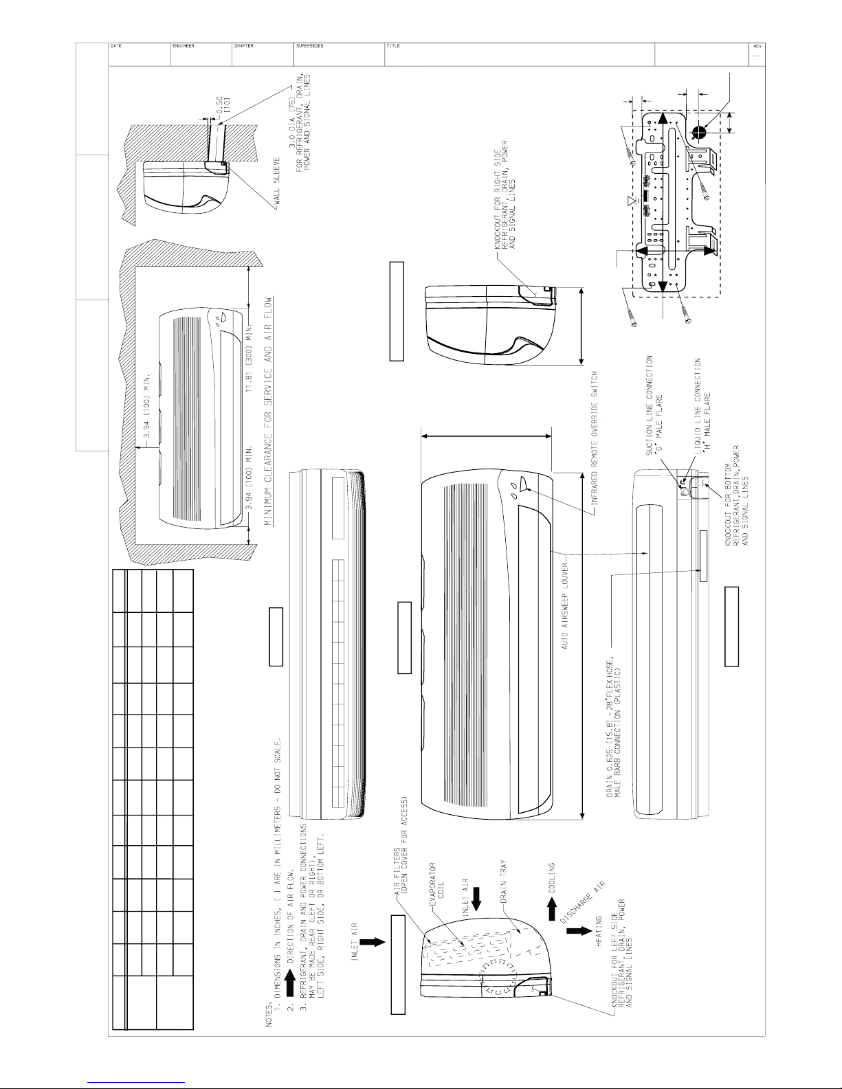
GENERAL
These instructions cover the installation, start−up and servicing of
DFC2A/DFC2H outdoor and DFF2A/DFF2H indoor units
cooling only and heat pump duct free systems. See Table 1 for
parts included. See Tables 2 and 3 for Physical Data.
SYSTEM REQUIREMENTS
IMPORTANT: The Indoor units & the inter units cable voltage
is 30 VDC.
IMPORTANT: Each refrigerant line must be insulated
Separately. See line sizing requirements in able 2.
S Consult local building codes and National Electrical Code
(NEC, U.S.A.) for special installation requirements.
Max. cable length
1V. Therefore max. length:
For #18 AWG 24.3 Feet (7.4 m)
For #16 AWG 37.7 Feet (11.5 m)
For #14 AWG 50.0 Feet (18 m)
. Total voltage drop should not exceed
!
CAUTION
UNIT COMPONENT DAMAGE
Failure to follow this caution may result in damage to unit
components.
Do not bury more than 36 in. of refrigerant pipe in the ground.
If any section of pipe is buried, there must be a 6 in. vertical
rise to the valve connections on the outdoor units. If more than
the recommended length is buried, refrigerant may migrate to
the cooler buried section during extended periods of system
shutdown.
S Use only type ”G” or ”C” fuses. Use single length power
cable without extension. Allow sufficient space for airflow
clearance on condensing units for wiring, refrigerant piping,
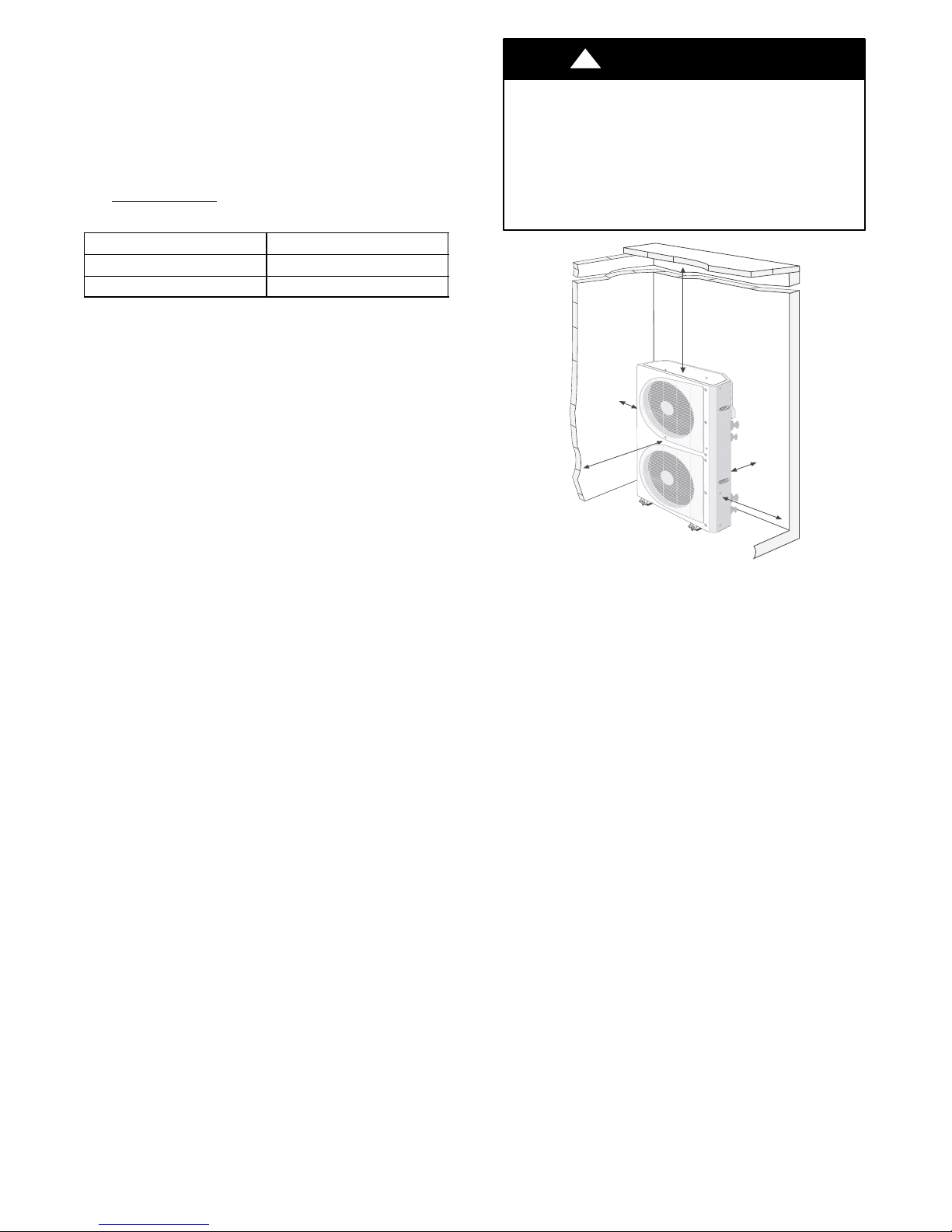
and servicing unit. See Fig. 1 and 2 for minimum required
distances between unit and walls or ceilings.
S Indoor and outdoor units should be installed at a Mini-
mum length of 10 ft. apart. Maximum line length of 50 ft.
and vertical separation of 30 ft.
S Do not install indoor units near a direct source of heat such
as direct sunlight, steam or flame.
TOP (min.)
2" (0.6m)
LEFT (min.)
6" (0.15m)
FRONT (min.)
2" (0.6m)
REAR (min.)
6" (0.15m)
RIGHT (min.)
2" (0.6m)
Fig. 1 — DFC2A/H318, 324 Outdoor Unit Clearances
2
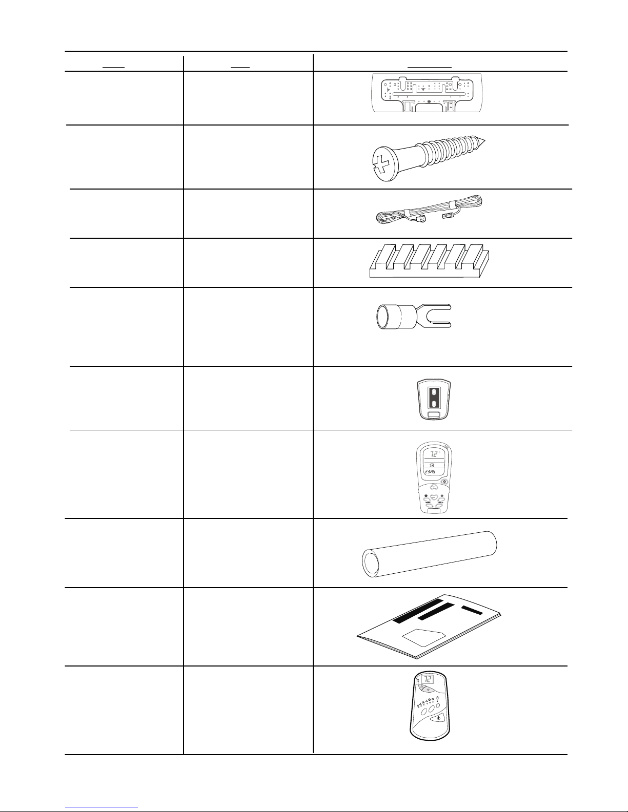
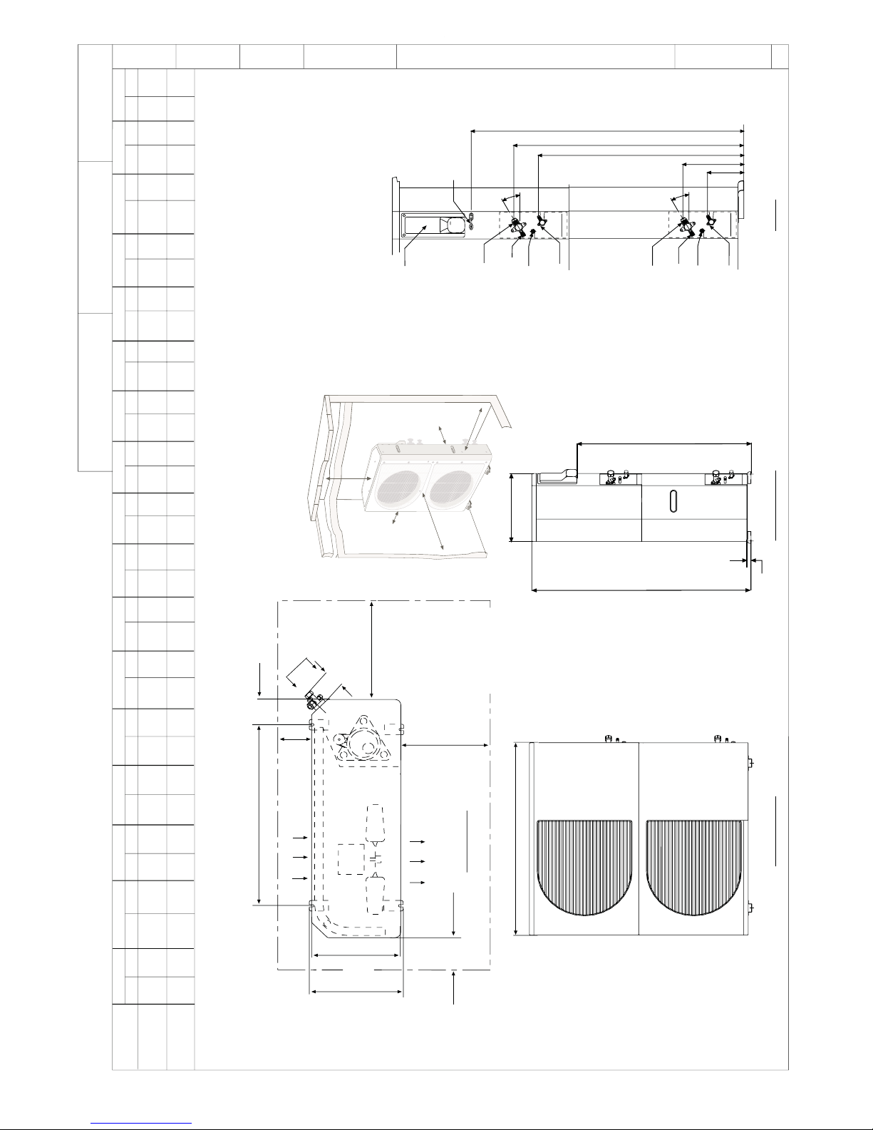
Table 1—Parts List — High Wall Units
ITEM
Mounting Bracket
Long Screws
Outdoor Sensor
Connecting
Cable
Absorption Cushions
Electric Terminals
QTY DIAGRAM
2 X 1
DFF2A/DFF2H 09, 12
2 X 8
2 X 1
(Available for HEAT PUMP ONLY)
4
2 X 8
Remote Controller
Mounting Bracket
Remote Controller
and Batteries
Insulation for
Indoor Fittings
Owner’s Manual
2 X
1 Mounting
Bracket with 2 screws
2 X 1
2 X 1
2 X 1
Wall−mounted
Receiver RTX
1
(OPTIONAL)
(Not Included)
NADA001TW
3
Table 2—Physical Data − Cooling Only
INDOOR UNIT
COOLING CAPACITY (Btuh) SEER 2 X 9,000
2 X DFF2AH09J1A 2 X DFF2AH12J1A
2 X 11,400
13.0
13.0
SYSTEM CHARGE (Ib)* 2 X 2.4 2 X 3.1
MOISTURE REMOVAL (pt/hr)
AIRFLOW (3 Speeds)
2 X 350 / 2 X 280 / 2 X 220 2 X 350 / 2 X 280 / 2 X 220
2 X 2.6 2 X 4.5
High / Med. / Low Cfm
DIMENSIONS LxHxW (in.) 32 3/32x10 15/64x7 9/32 32 3/32x10 15/64x7 9/32
REFRIGERANT TYPE R−22 R−22
NET WEIGHT (Ib) 2 X 19.0 2 X 19.0
OUTDOOR UNIT DFC2A318J2A DFC2A324J2A
TUBE CONNECTIONS
30/30/50 30/30/50
Vert Lift/Vert Drop/Max Length (ft)
NOMINAL LINE SIZING
1/4...1/2 1/4...1/2
Mixed Phase...Suction (in.)
COMPRESSOR TYPE Panasonic−2R13S126A6F Panasonic−2P17SR126B1A
DIMENSIONS LxHxW(in.) 35.5 X 49.5 X 12.6 35.5 X 49.5 X 12.6
NET WEIGHT (Ib) 226 228
METERING TYPE Piston (Accurator) Piston (Accurator)
LEGEND Accurator is non−serviceable
SEER — Seasonal Energy Efficiency Ratio
*Units are shipped with a factory charge based on 25 ft of refrigerant lines.
Table 3—Physical Data − Heat Pump
INDOOR UNIT
COOLING CAPACITY (Btuh)
SEER
HEATING CAPACITY (Btuh)
HSPF
2 X DFF2AH09J1A 2 X DFF2AH12J1A
2 X 9,000
13.0
17,200
7.7
2 X 11,400
13.0
23,600
7.7
SYSTEM CHARGE (Ib)* 2 X 2.4 2 X 3.1
MOISTURE REMOVAL (pt/hr)
AIRFLOW (3 Speeds)
2 X 350 / 2 X 280 / 2 X 220 2 X 350 / 2 X 280 / 2 X 220
2 X 2.6 2 X 4.5
High / Med. / Low Cfm
DIMENSIONS LxHxW (in.) 32 3/32x10 15/64x7 9/32 32 3/32x10 15/64x7 9/32
REFRIGERANT TYPE R−22 R−22
NET WEIGHT (Ib) 2 X 19.0 2 X 19.0
OUTDOOR UNIT DFC2A318J2A DFC2A324J2A
TUBE CONNECTIONS
30/30/50 30/30/50
Vert Lift/Vert Drop/Max Length (ft)
NOMINAL LINE SIZING
1/4...1/2 1/4...1/2
Mixed Phase...Suction (in.)
COMPRESSOR TYPE Panasonic−2R13S126A6F Panasonic−2P17SR126B1A
DIMENSIONS LxHxW(in.) 35.5 X 49.5 X 12.6 35.5 X 49.5 X 12.6
SHIPPING WEIGHT (Ib) 226 228
METERING TYPE Piston (Accurator) Piston (Accurator)
LEGEND Accurator is non−serviceable
HPSF — Heating Seasonal Performance Factor
SEER — Seasonal Energy Efficiency Ratio
*Units are shipped with a factory charge based on 25 ft of refrigerant lines.
NOTE: Standard Ambient Operating Limitations − 55 F to 125 F (12.7 C to 51.6 C).
4
ł46 mm
)"5.2(
F
K
L
E
D
TINU CBA
D
E
F
G
LH
thgieW
]hcnI[
]mm[
K
gK )5.8(
bl 7.81
gK )5.8(
]hcnI[
]mm[
WEIV TNORF
WEIV EDIS THGIR
WEIV MOTTOB
WEIV EDIS TFEL
WEIV POT
”A“
”C“
”B“
20/06/2006 GAD L EITANC
NEW
)581()062()518()032()536( )53.6()7.21()04()05()72(
80.23 69.160.14/12/175.160.95282.732.01
)062()518()032()5
36()581()7.21()04()05()72()53.6(
4/12/152
bl 7.81
69.160.175.160.9
82.732.0180.23
A1J90HA2FFD
A1J90HH2FFD
A1J21HA2FFD
A1J21HH2FFD
PCI
5
.TGW GNITAREPO
] gk [
.SBL
)ERALF DIUQIL( R
] mm [
.SEHCNI
)ERALF NOITCUS( P
] mm [
.SEHCNI
] mm [
.SEHCNI
N
] mm [
.SEHCNI
M
] mm [
.SEHCNI
] mm [
.SEHCNI
] mm [
.SEHCNI
J2
] mm [
.SEHCNI
] mm [
.SEHCNI
] mm [
.SEHCNI
G
] m
m
[
.SE
HCNI
F
] mm [
.SE
HCNI
E
] mm [
.SEHCNI
D
] mm [
.SEHCNI
C
] mm [
.SEHCNI
B
] m
m [
.SEHCNI
A
EZIS TINU
:SETON
MUMINIM 6 WOLLA - LLAW GNICAF LIOC HTIW ,SECNARAELC DERIUQER .1
,DNE & EDIS LIOC NO ECNARAELC MU
MINIM 6 WOLLA - LLAW GNICAF LIOC HTIW 1.1
.EDIS NAF DNE ROSSERPMOC NO ECNARAELC MUMINIM TEEF 2 DNA
,DNE LIOC NO 6 DNA EDIS NAF NO ECNARAELC MUMINIM 2 WOLLA - LLAW GNICAF NAF HTIW 2.1
.EDIS
LIOC DNE ROSSERPMOC NO ECNARAELC MUMINIM TEEF 2 DNA
.TINU FO POT EHT REVO ECNARAELC MUMINIM T
EEF 2 WOLLA 3.1
FO TELNI RETNE TON SEOD ENO FO EGRAHCSID 0S STINU EGNARRA ,NOITACILPPA TINU-ITLUM
HTIW 4.1
.REHTO
.CIRTEM NI ERA SISEHTNERAP NI SNOISNEMID .2
.YLPPUS REWOP DLEIF ROF ELOH .AID 521.1 HTIW TEKCARB .3
DATE
30/06/06
ENGINEER
EITANC
DRAFTER
EITANC
SUPERSEDES
NEW
REV
-
WEIV POT
EGRAHCSID RIA
NI RIA
VIEW
SECNARAELC MUMINIM
1 ETON EES
GNITUOM
TOLS
& NOITCENNOC REWOP DLEIF
NOITCENNOC LORTNOC
REVOC SIHT REDNU
3 ETON EES
PYT º03
ENIL ROPAV .AID ”P“
NOITCEN
NOC ERALF
TROP ECIVRES
NOITCENNOC ERALF ”52.
TROP ECIVRES
)ENIL DIUQIL MORF(
NOITCENNOC ERALF ”52.
ENIL DIU
QIL .AID ”R“
NOITCENNOC ERALF
7.0
]MM81[
WEIV TNORF
.niM
]M6.0[ ’2
.niM
]M51.0[ ”6
.niM
]M51.0[ ”6
.niM
]M6.0[ ’2
.niM
]M6.0[ ’2
.niM
]M6.0[ ’2
.niM
]M51.0[ ”6
.niM
]M5
1.0[ ”6
”G“”E“
”F“
”D“
“A”
“L”
”C“
”A“
”N“
”B“
”M“
”2K“
”2J“
”1K“
”1J“
PYT º03
ENIL ROPAV .AID ”P“
NOITCENNOC ERALF
TROP ECIVRES
NOITCENNOC ERALF ”52.
TROP ECIVRES
)ENIL DIUQIL M
ORF(
NOITCENNOC ERALF ”52.
ENIL DIUQIL .AID ”R“
NOITCENNOC ERALF
.niM
]M51.0[ ”6
L2K1K1J
5.20162253.64/17.212/180017.9357.77913.490163153.58267.420.415530094.537521
4.30182253.64/17.212/18001791
9013.463153.57.425530.414.530097521
5.94
8265.94
6276.82
6.8257.7627
3180.23
0.23318
4521.2
4521.2
7.73759
7.937597.73
0236.21
6.21 023
8739.41
9.41873
WEIV EDIS THGIR
”A“ WEIV
A2J813A2CFD
A2J813H2CFD
A2J423A2CFD
A2J423H2CFD
PCI
6
 Loading...