

International comfort products DFS2A318J2A, DFS2A/H 2X09, DFS2H318J2A, DFS2A/H 2X12, DFS2A324J2A Installation, Start-up And Service Instructions Manual
...Page 1
Cooling Model Heat Pump
DFS2A318J2A DFS2H318J2A
DFS2A324J2A DFS2H324J2A
Installation, Start-Up, and Service Instructions
CONTENTS
Page
SAFETY CONSIDERATIONS 1. . . . . . . . . . . . . . . . . . . . . .
GENERAL 1−7. . . . . . . . . . . . . . . . . . . . . . . . . . . . . . . . . . . . .
INSTALLATION 7−14. . . . . . . . . . . . . . . . . . . . . . . . . . . . . .
Indoor Unit Installation 7. . . . . . . . . . . . . . . . . . . . . . . .
Outdoor Unit Installation 9. . . . . . . . . . . . . . . . . . . . . . . .
Power Supply 10. . . . . . . . . . . . . . . . . . . . . . . . . . . . . . . .
Leak Test 10. . . . . . . . . . . . . . . . . . . . . . . . . . . . . . . . . . . . .
Wiring Diagrams 12−13. . . . . . . . . . . . . . . . . . . . . . . . . . .
START−UP 14. . . . . . . . . . . . . . . . . . . . . . . . . . . . . . . . . . . .
System Checks 14. . . . . . . . . . . . . . . . . . . . . . . . . . . . . . . .
CARE AND MAINTENANCE 14. . . . . . . . . . . . . . . . . . . . . . .
Outdoor Units 14. . . . . . . . . . . . . . . . . . . . . . . . . . . . . . . . .
Indoor Units 14. . . . . . . . . . . . . . . . . . . . . . . . . . . . . . . . . . .
To Clean the Indoor Unit Front Panel 14. . . . . . . . . . . .
To Clean Indoor Coil 14. . . . . . . . . . . . . . . . . . . . . . . . . . .
Air Filters for Indoor Units 14. . . . . . . . . . . . . . . . . . . . . .
SERVICE 15. . . . . . . . . . . . . . . . . . . . . . . . . . . . . . . . . . . . . . .
TROUBLESHOOTING 16−19. . . . . . . . . . . . . . . . . . . . . . . .
421 01 9219 00
R−22
Installing, starting up, and servicing air−conditioning equipment
can be hazardous due to system pressures, electrical components,
and equipment location (roofs, elevated structures, etc.).
Only trained, qualified installers and service mechanics should
install, start−up, and service this equipment.
Untrained personnel can perform basic maintenance functions
such as cleaning coils. All other operations should be performed
by trained service personnel.
When working on the equipment, observe precautions in the
literature and on tags, stickers, and labels attached to the equipment.
Follow all safety codes. Wear safety glasses and work gloves.
Keep quenching cloth and fire extinguisher nearby when brazing.
Use care in handling, rigging, and setting bulky equipment.
51302618919−B NOV 06
DFS2A/H 2X09, 2X12
Duct Free Systems
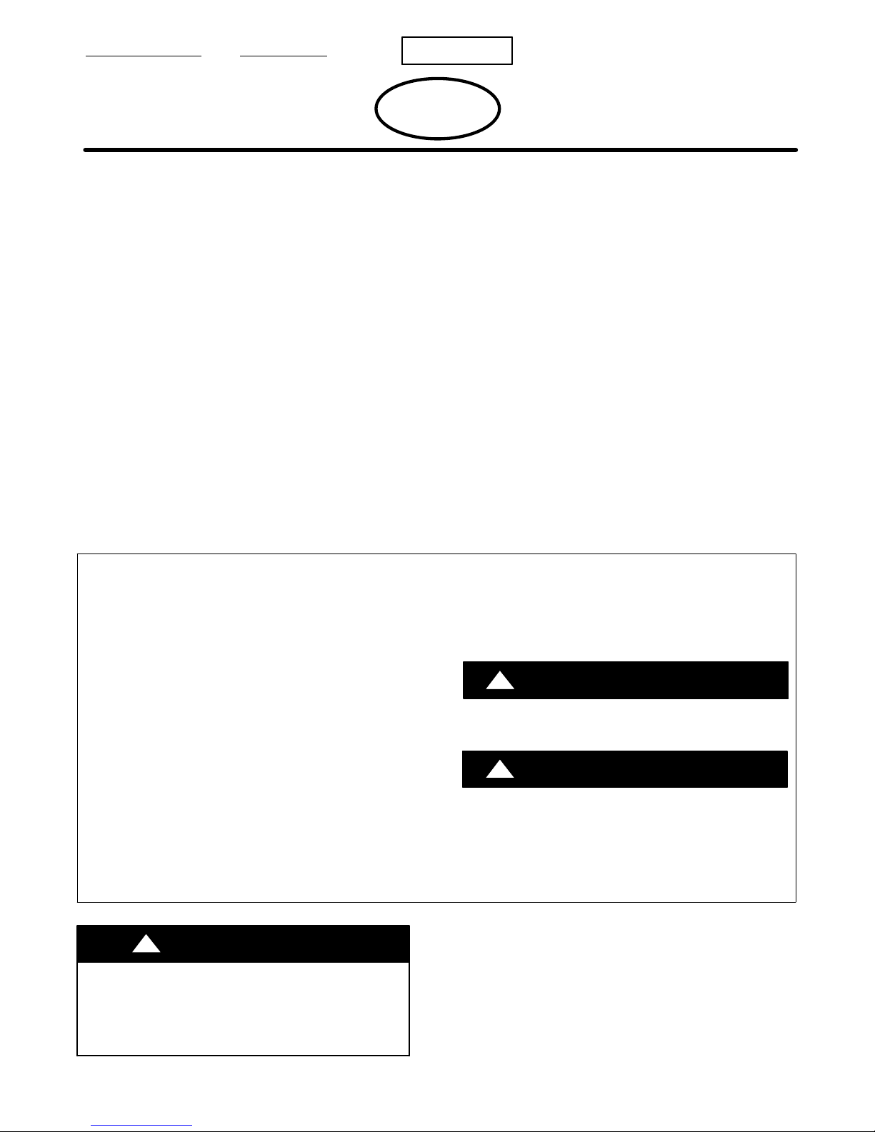
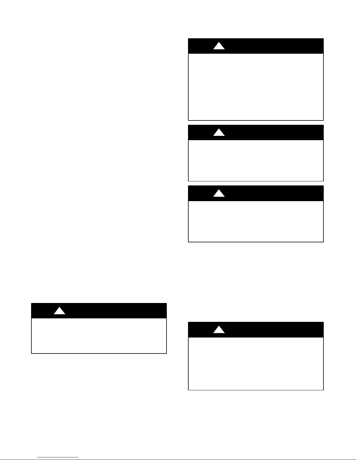
SAFETY CONSIDERATIONS
Safety Labeling and Signal Words
DANGER, WARNING, CAUTION, and
NOTE
The signal words DANGER, WARNING, CAUTION, and
NOTE are used to identify levels of hazard serious-
ness. The signal word DANGER is only used on
product labels to signify an immediate hazard. The
signal words WARNING, CAUTION, and NOTE will
be used on product labels and throughout this manual and other manuals that may apply to the product.
DANGER − Immediate hazards which will result in se-
vere personal injury or death.
WARNING − Hazards or unsafe practices which could
result in severe personal injury or death.
CAUTION − Hazards or unsafe practices which may re-
sult in minor personal injury or product or property
damage.
NOTE − Used to highlight suggestions which will result in
enhanced installation, reliability, or operation.
!
ELECTRICAL SHOCK HAZARD
Failure to follow this warning could result in personal
injury or death.
Before installing or servicing system, always turn off main
power to system and install lockout tag on disconnect.
There may be more than one disconnect switch.
WARNING
Signal Words in Manuals
The signal word WARNING is used throughout this
manual in the following manner:
WARNING
!
The signal word CAUTION is used throughout this
manual in the following manner:
!
Signal Words on Product Labeling
Signal words are used in combination with colors and/or
pictures on product labels.
WARNING
CAUTION
GENERAL
These instructions cover the installation, start−up and servicing of
DFC2A/DFC2H outdoor and DFF2A/DFF2H indoor units
cooling only and heat pump duct free systems. See Table 1 for
parts included. See Tables 2 and 3 for Physical Data.
Page 2
SYSTEM REQUIREMENTS
IMPORTANT: The Indoor units & the inter units cable voltage
is 30 VDC.
IMPORTANT: Each refrigerant line must be insulated
Separately. See line sizing requirements in able 2.
S Consult local building codes and National Electrical Code
(NEC, U.S.A.) for special installation requirements.
Max. cable length
1V. Therefore max. length:
For #18 AWG 24.3 Feet (7.4 m)
For #16 AWG 37.7 Feet (11.5 m)
For #14 AWG 50.0 Feet (18 m)
. Total voltage drop should not exceed
!
CAUTION
UNIT COMPONENT DAMAGE
Failure to follow this caution may result in damage to unit
components.
Do not bury more than 36 in. of refrigerant pipe in the ground.
If any section of pipe is buried, there must be a 6 in. vertical
rise to the valve connections on the outdoor units. If more than
the recommended length is buried, refrigerant may migrate to
the cooler buried section during extended periods of system
shutdown.
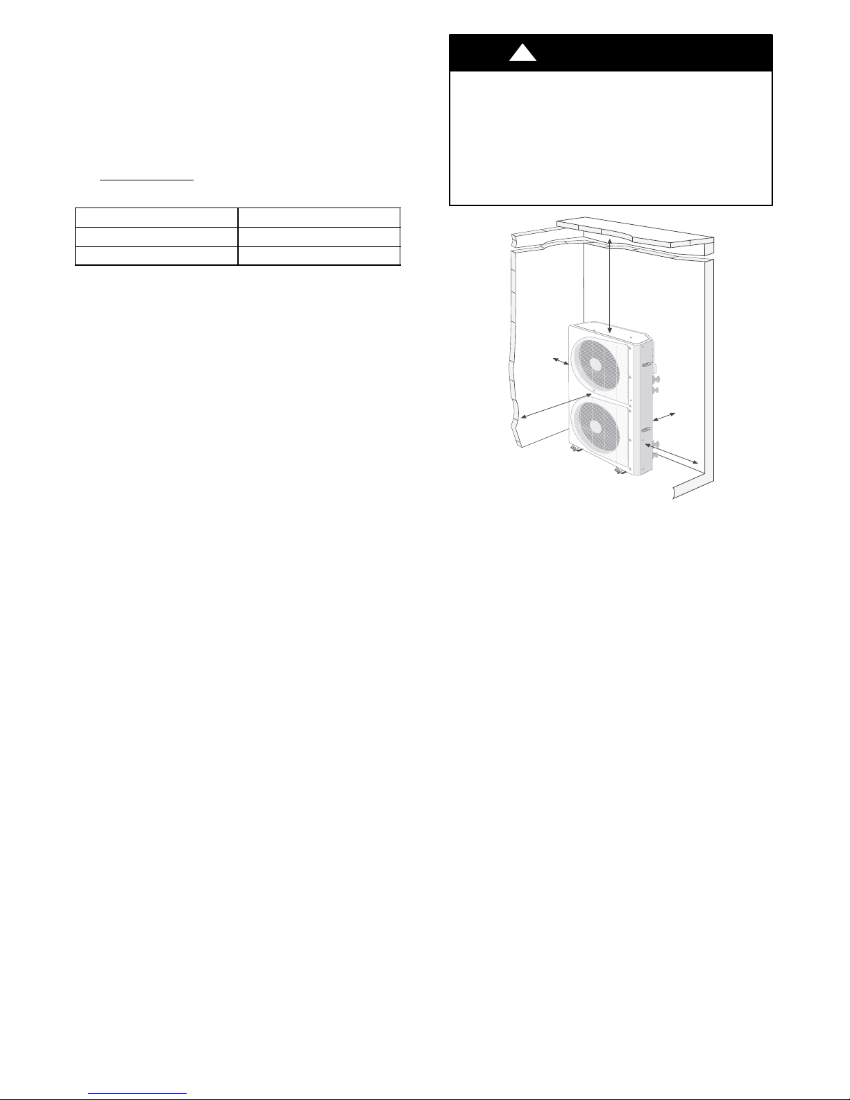
S Use only type ”G” or ”C” fuses. Use single length power
cable without extension. Allow sufficient space for airflow
clearance on condensing units for wiring, refrigerant piping,
and servicing unit. See Fig. 1 and 2 for minimum required
distances between unit and walls or ceilings.
S Indoor and outdoor units should be installed at a Mini-
mum length of 10 ft. apart. Maximum line length of 50 ft.
and vertical separation of 30 ft.
S Do not install indoor units near a direct source of heat such
as direct sunlight, steam or flame.
TOP (min.)
2" (0.6m)
LEFT (min.)
6" (0.15m)
FRONT (min.)
2" (0.6m)
REAR (min.)
6" (0.15m)
RIGHT (min.)
2" (0.6m)
Fig. 1 — DFC2A/H318, 324 Outdoor Unit Clearances
2
Page 3
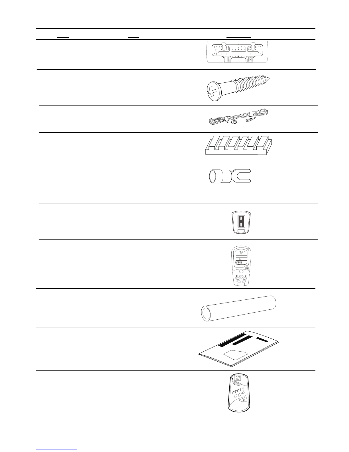
Table 1—Parts List — High Wall Units
ITEM
Mounting Bracket
Long Screws
Outdoor Sensor
Connecting
Cable
Absorption Cushions
Electric Terminals
QTY DIAGRAM
2 X 1
DFF2A/DFF2H 09, 12
2 X 8
2 X 1
(Available for HEAT PUMP ONLY)
4
2 X 8
Remote Controller
Mounting Bracket
Remote Controller
and Batteries
Insulation for
Indoor Fittings
Owner’s Manual
2 X
1 Mounting
Bracket with 2 screws
2 X 1
2 X 1
2 X 1
Wall−mounted
Receiver RTX
1
(OPTIONAL)
(Not Included)
NADA001TW
3
Page 4
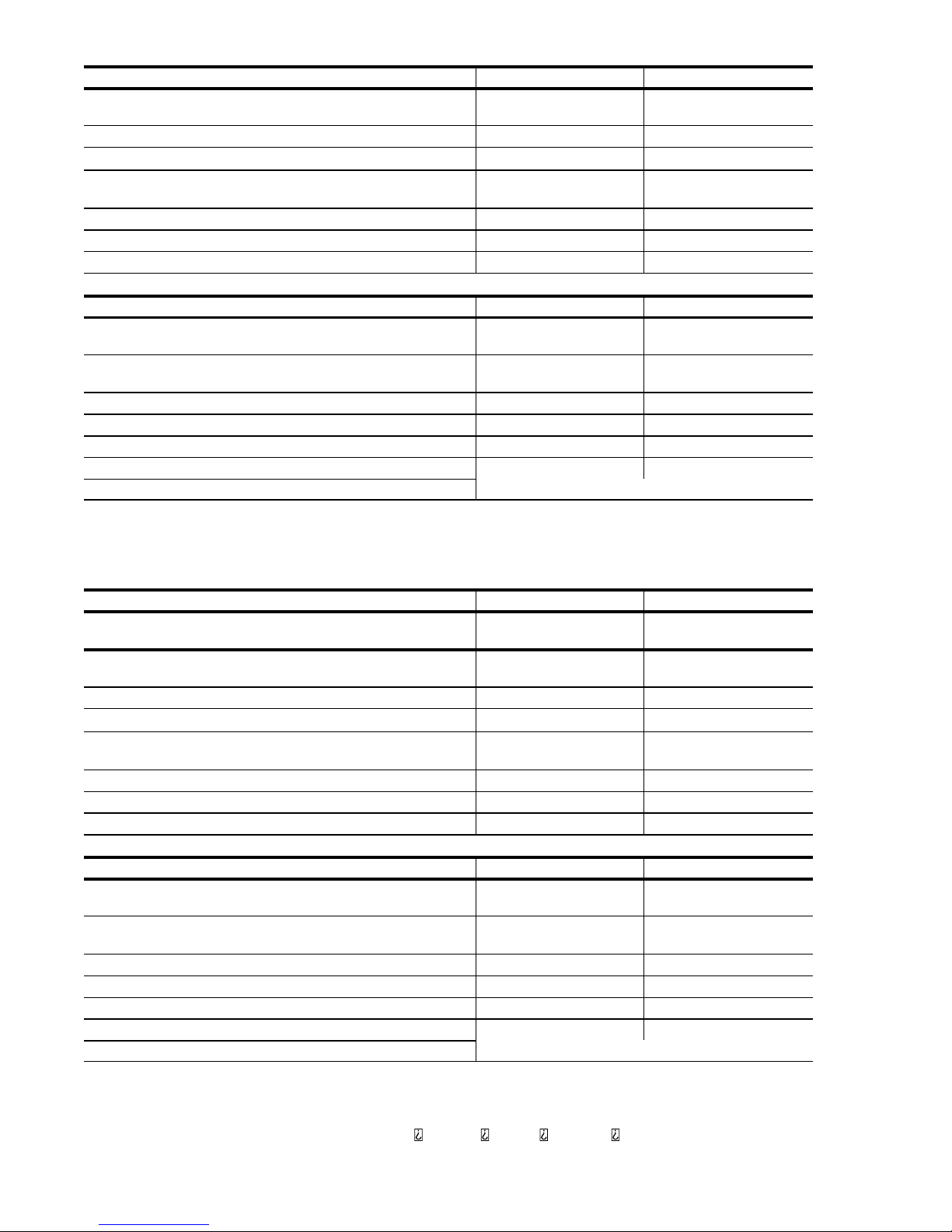
Table 2—Physical Data − Cooling Only
INDOOR UNIT
COOLING CAPACITY (Btuh) SEER 2 X 9,000
2 X DFF2AH09J1A 2 X DFF2AH12J1A
2 X 11,400
13.0
13.0
SYSTEM CHARGE (Ib)* 2 X 2.4 2 X 3.1
MOISTURE REMOVAL (pt/hr)
AIRFLOW (3 Speeds)
2 X 350 / 2 X 280 / 2 X 220 2 X 350 / 2 X 280 / 2 X 220
2 X 2.6 2 X 4.5
High / Med. / Low Cfm
DIMENSIONS LxHxW (in.) 32 3/32x10 15/64x7 9/32 32 3/32x10 15/64x7 9/32
REFRIGERANT TYPE R−22 R−22
NET WEIGHT (Ib) 2 X 19.0 2 X 19.0
OUTDOOR UNIT DFC2A318J2A DFC2A324J2A
TUBE CONNECTIONS
30/30/50 30/30/50
Vert Lift/Vert Drop/Max Length (ft)
NOMINAL LINE SIZING
1/4...1/2 1/4...1/2
Mixed Phase...Suction (in.)
COMPRESSOR TYPE Panasonic−2R13S126A6F Panasonic−2P17SR126B1A
DIMENSIONS LxHxW(in.) 35.5 X 49.5 X 12.6 35.5 X 49.5 X 12.6
NET WEIGHT (Ib) 226 228
METERING TYPE Piston (Accurator) Piston (Accurator)
LEGEND Accurator is non−serviceable
SEER — Seasonal Energy Efficiency Ratio
*Units are shipped with a factory charge based on 25 ft of refrigerant lines.
Table 3—Physical Data − Heat Pump
INDOOR UNIT
COOLING CAPACITY (Btuh)
SEER
HEATING CAPACITY (Btuh)
HSPF
2 X DFF2AH09J1A 2 X DFF2AH12J1A
2 X 9,000
13.0
17,200
7.7
2 X 11,400
13.0
23,600
7.7
SYSTEM CHARGE (Ib)* 2 X 2.4 2 X 3.1
MOISTURE REMOVAL (pt/hr)
AIRFLOW (3 Speeds)
2 X 350 / 2 X 280 / 2 X 220 2 X 350 / 2 X 280 / 2 X 220
2 X 2.6 2 X 4.5
High / Med. / Low Cfm
DIMENSIONS LxHxW (in.) 32 3/32x10 15/64x7 9/32 32 3/32x10 15/64x7 9/32
REFRIGERANT TYPE R−22 R−22
NET WEIGHT (Ib) 2 X 19.0 2 X 19.0
OUTDOOR UNIT DFC2A318J2A DFC2A324J2A
TUBE CONNECTIONS
30/30/50 30/30/50
Vert Lift/Vert Drop/Max Length (ft)
NOMINAL LINE SIZING
1/4...1/2 1/4...1/2
Mixed Phase...Suction (in.)
COMPRESSOR TYPE Panasonic−2R13S126A6F Panasonic−2P17SR126B1A
DIMENSIONS LxHxW(in.) 35.5 X 49.5 X 12.6 35.5 X 49.5 X 12.6
SHIPPING WEIGHT (Ib) 226 228
METERING TYPE Piston (Accurator) Piston (Accurator)
LEGEND Accurator is non−serviceable
HPSF — Heating Seasonal Performance Factor
SEER — Seasonal Energy Efficiency Ratio
*Units are shipped with a factory charge based on 25 ft of refrigerant lines.
NOTE: Standard Ambient Operating Limitations − 55 F to 125 F (12.7 C to 51.6 C).
4
Page 5
ł46 mm
)"5.2(
F
K
L
E
D
TINU CBA
D
E
F
G
LH
thgieW
]hcnI[
]mm[
K
gK )5.8(
bl 7.81
gK )5.8(
]hcnI[
]mm[
WEIV TNORF
WEIV EDIS THGIR
WEIV MOTTOB
WEIV EDIS TFEL
WEIV POT
”A“
”C“
”B“
20/06/2006 GAD L EITANC
NEW
)581()062()518()032()536( )53.6()7.21()04()05()72(
80.23 69.160.14/12/175.160.95282.732.01
)062()518()032()5
36()581()7.21()04()05()72()53.6(
4/12/152
bl 7.81
69.160.175.160.9
82.732.0180.23
A1J90HA2FFD
A1J90HH2FFD
A1J21HA2FFD
A1J21HH2FFD
PCI
5
Page 6
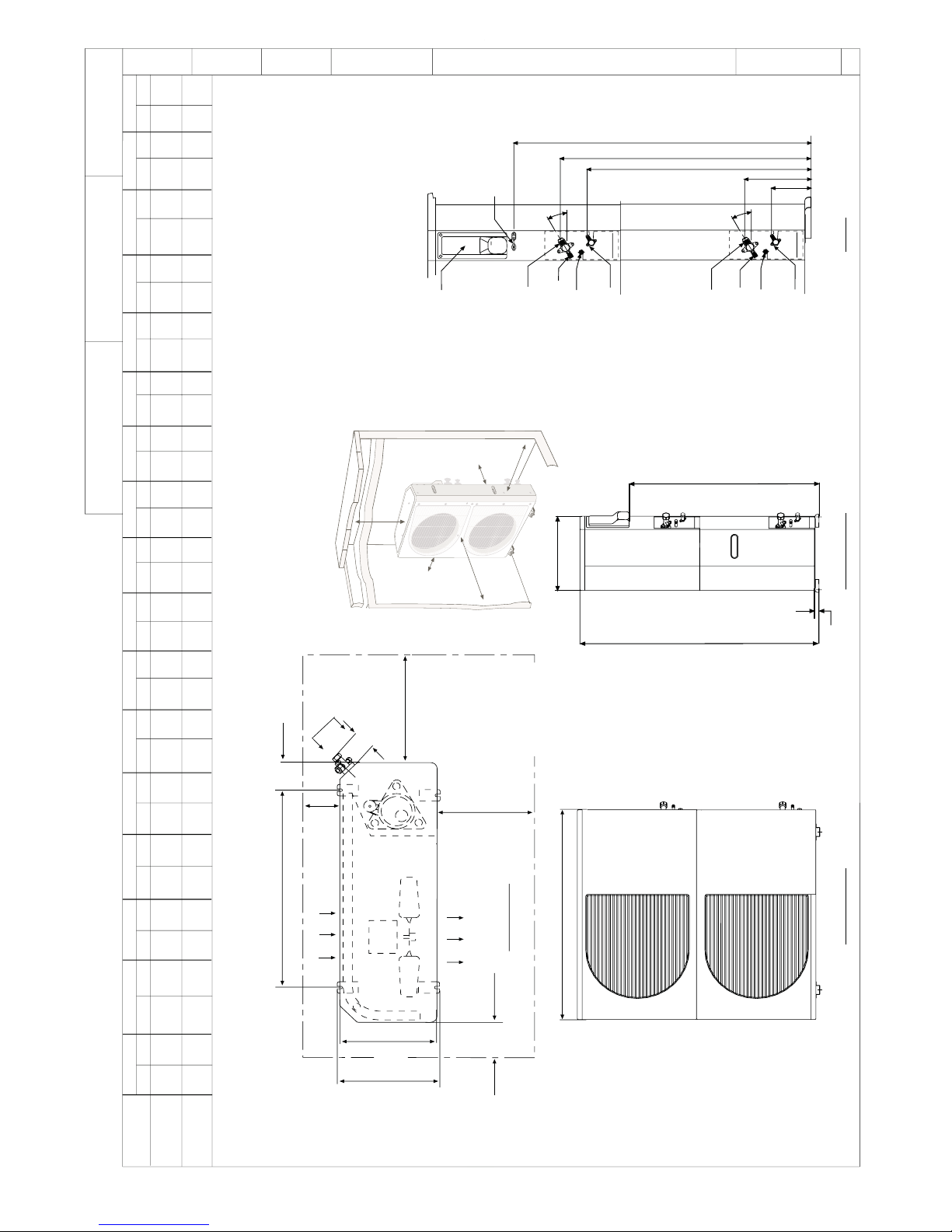
.TGW GNITAREPO
] gk [
.SBL
)ERALF DIUQIL( R
] mm [
.SEHCNI
)ERALF NOITCUS( P
] mm [
.SEHCNI
] mm [
.SEHCNI
N
] mm [
.SEHCNI
M
] mm [
.SEHCNI
] mm [
.SEHCNI
] mm [
.SEHCNI
J2
] mm [
.SEHCNI
] mm [
.SEHCNI
] mm [
.SEHCNI
G
] m
m
[
.SE
HCNI
F
] mm [
.SE
HCNI
E
] mm [
.SEHCNI
D
] mm [
.SEHCNI
C
] mm [
.SEHCNI
B
] m
m [
.SEHCNI
A
EZIS TINU
:SETON
MUMINIM 6 WOLLA - LLAW GNICAF LIOC HTIW ,SECNARAELC DERIUQER .1
,DNE & EDIS LIOC NO ECNARAELC MU
MINIM 6 WOLLA - LLAW GNICAF LIOC HTIW 1.1
.EDIS NAF DNE ROSSERPMOC NO ECNARAELC MUMINIM TEEF 2 DNA
,DNE LIOC NO 6 DNA EDIS NAF NO ECNARAELC MUMINIM 2 WOLLA - LLAW GNICAF NAF HTIW 2.1
.EDIS
LIOC DNE ROSSERPMOC NO ECNARAELC MUMINIM TEEF 2 DNA
.TINU FO POT EHT REVO ECNARAELC MUMINIM T
EEF 2 WOLLA 3.1
FO TELNI RETNE TON SEOD ENO FO EGRAHCSID 0S STINU EGNARRA ,NOITACILPPA TINU-ITLUM
HTIW 4.1
.REHTO
.CIRTEM NI ERA SISEHTNERAP NI SNOISNEMID .2
.YLPPUS REWOP DLEIF ROF ELOH .AID 521.1 HTIW TEKCARB .3
DATE
30/06/06
ENGINEER
EITANC
DRAFTER
EITANC
SUPERSEDES
NEW
REV
-
WEIV POT
EGRAHCSID RIA
NI RIA
VIEW
SECNARAELC MUMINIM
1 ETON EES
GNITUOM
TOLS
& NOITCENNOC REWOP DLEIF
NOITCENNOC LORTNOC
REVOC SIHT REDNU
3 ETON EES
PYT º03
ENIL ROPAV .AID ”P“
NOITCEN
NOC ERALF
TROP ECIVRES
NOITCENNOC ERALF ”52.
TROP ECIVRES
)ENIL DIUQIL MORF(
NOITCENNOC ERALF ”52.
ENIL DIU
QIL .AID ”R“
NOITCENNOC ERALF
7.0
]MM81[
WEIV TNORF
.niM
]M6.0[ ’2
.niM
]M51.0[ ”6
.niM
]M51.0[ ”6
.niM
]M6.0[ ’2
.niM
]M6.0[ ’2
.niM
]M6.0[ ’2
.niM
]M51.0[ ”6
.niM
]M5
1.0[ ”6
”G“”E“
”F“
”D“
“A”
“L”
”C“
”A“
”N“
”B“
”M“
”2K“
”2J“
”1K“
”1J“
PYT º03
ENIL ROPAV .AID ”P“
NOITCENNOC ERALF
TROP ECIVRES
NOITCENNOC ERALF ”52.
TROP ECIVRES
)ENIL DIUQIL M
ORF(
NOITCENNOC ERALF ”52.
ENIL DIUQIL .AID ”R“
NOITCENNOC ERALF
.niM
]M51.0[ ”6
L2K1K1J
5.20162253.64/17.212/180017.9357.77913.490163153.58267.420.415530094.537521
4.30182253.64/17.212/18001791
9013.463153.57.425530.414.530097521
5.94
8265.94
6276.82
6.8257.7627
3180.23
0.23318
4521.2
4521.2
7.73759
7.937597.73
0236.21
6.21 023
8739.41
9.41873
WEIV EDIS THGIR
”A“ WEIV
A2J813A2CFD
A2J813H2CFD
A2J423A2CFD
A2J423H2CFD
PCI
6
Page 7

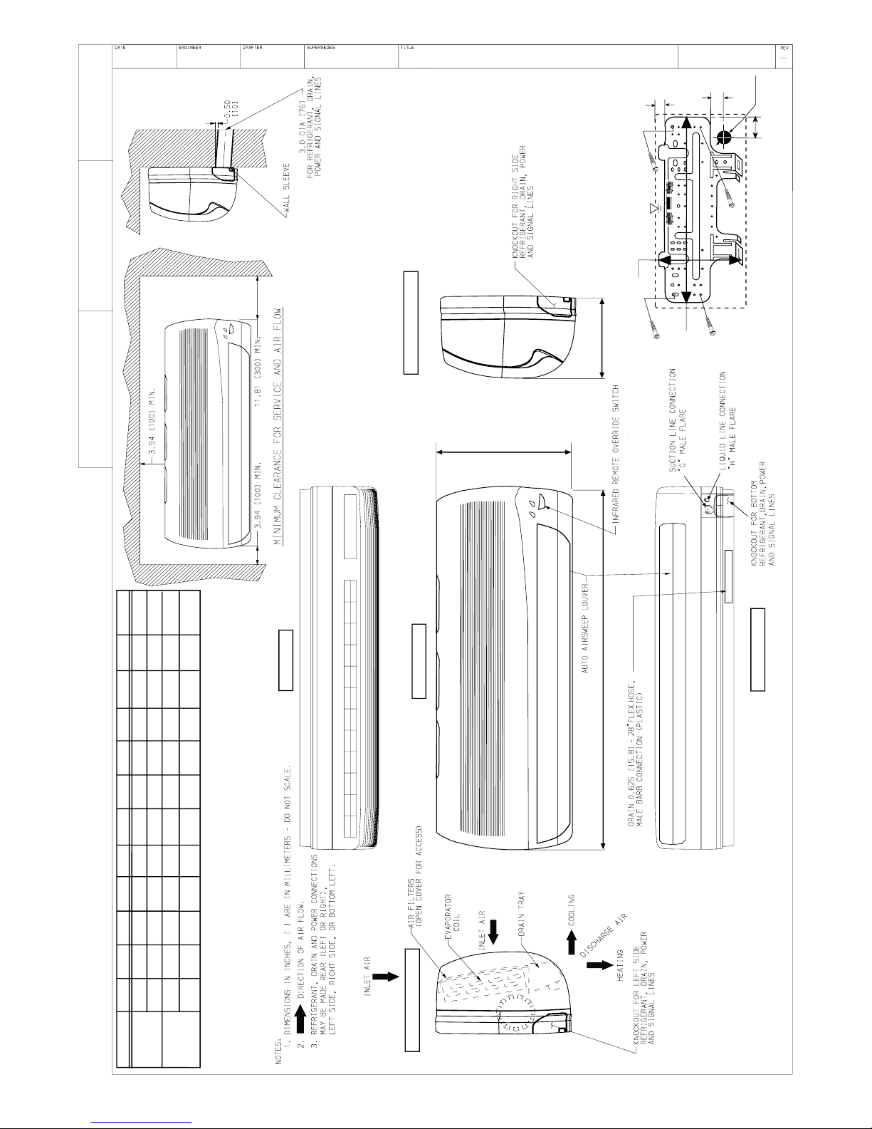
Fig. 2 — Indoor Unit Clearances
INSTALLATION
Plan the installation carefully to avoid component failures and
make installation easier.
Indoor Unit Installation
REFRIGERANT LINE ROUTING — The refrigerant lines may
be routed in any of the four directions shown in Fig. 3.
INSTALL THE MOUNTING BRACKET
1. Carefully remove the mounting bracket, which is connected to the back of the indoor unit’s base with screws.
2. Position the mounting bracket on the wall and level it using a spirit level (see Fig. 2 for minimum required clearance distances).
3. Mark the four drilling holes on the wall, as they appear in
Fig. 4.
4. Drill the holes, insert the wall plugs and use four long
screws to attach the mounting bracket to the wall.
5. Check that the bracket is leveled and securely fastened to
the wall.
DRILL A HOLE IN THE WALL FOR DRAINAGE AND
INTER−UNIT CONNECTIONS
To make the connections between the indoor and outdoor units,
drill a 2.5−in. hole through the wall for the refrigerant lines,
drainage hose and control cable passage as shown in Fig. 5.
1. Mark the center of the hole to be drilled according to the refrigerant line routing used and dimensions shown in Fig. 4.
2. Make sure to drill outwards and downwards, so that the
opening in the outside wall is at least 1/2” lower than the
opening on the inside.
3. Make sure the drainage hose is at the bottom side of the
hole.
4. If refrigerant line route no. 1,2 or 4 are used, use a small
saw blade to carefully remove the corresponding plastic
covering on the side panel.
5. Run the outdoor sensor cable, electrical cable, refrigerant
lines, and drainage tube through the hole.
6. Fill the remaining wall hole gap with an appropriate sealant material.
Fig. 3 — Refrigerant Lines
09, 12
G-2
09, 12
G-2
2.6
2.1
ALL DIMENSIONS ARE IN inches
66
54
ALL DIMENSIONS ARE IN mm
25
17.72
9.84
635
450
250
3.15
10.63 4.92
80
270 125
3.5
1.77
0.35
1.77
A
90
45
9
45
A
Fig. 4 — Mounting Bracket DFF2A/DFF2H 09, 12
2.5-IN.
Fig. 5 — Drill Holes
10.24
2.5
260
64
7
Page 8

WIRE THE INDOOR UNIT
FILTER
IR
RECEIVER
POWER/AIRCOND
TIMER
FUSE
AUTO/OFF
FILTER RESET
SERVICE LED
POWER/AIRCOND
TIMER
FUSE
AUTO/OFF
FILTER RESET
SERVICE LED
AUTO/OFF
FILTER RESET
SERVICE LED
1. Strip the cables back 1/4 inch.
2. Remove the unit’s front panel by lifting the lower part and
pulling it gently outward and upward. See Fig. 6.
3. Remove the two screws from the control box cover and
take off the cover. See Fig. 7. Save the screws to reassemble.
NOTE: In general wiring the indoor unit does not require the
removal of the grille frame but in case of need do as follow:
4. Remove the two screws from the air discharge opening.
Save the screws to reassemble. See Fig. 7A.
S Pull downwards and outwards on the bottom of the grille
and gently raise the frame of the top of the unit.
S Once all covers are off, mount the unit onto the wall mount-
ing bracket. See Fig. 8.
NOTE: Leave covers off until after the Making Drainage
Connections section.
S Route the interconnecting unit’s electric cable and the out-
door sensor cable towards the lower right hand corner of the
indoor unit.
S Make sure that the wires are connected in accordance with
the wiring diagram on the inside of the unit front cover or
within this instruction manual.
S Secure the control cables to the strain relief.
S For heat pump systems only, connect the outdoor sensor
TH3 to its mating black terminal. See Fig. 9.
!
WARNING
Fig. 6 — Remove Grille Insert
Fig. 7 — Remove Control Cover
Fig. 7a — Remove the screws from the air discharge
opening.
Mount the indoor unit on the mounting bracket
FIRE HAZARD
Failure to follow this warning could result in personal
injury, death and or property damage.
Make sure that all wires and screws are firmly fastened.
REASSEMBLE
1. Connect the display connector to the display panel printed
circuit board.
2. Put the control box cover and grille frame back on using
the appropriate screws (Steps 3 and 4 of Wire the Indoor
Unit section). Put the grille insert back on.
Model−2 X 12 DIP Switches location
Model−2 X 09 DIP Switches location
Model−2 X 12 DIP Switches location
Model−2 X 09 DIP Switches location
HEAT PUMP
(on the control box side)
HEAT PUMP
(on the control box side)
COOLING ONLY
(on the control box side)
COOLING ONLY
(on the control box side)
Standard Dip Switches
status from the factory
Gently push with the arrow direction
Fig. 8 — Indoor Unit Mounting
Inter unit
terminal block
30VDC
Display
Connection
TH1
TH2
TH3
(Heat Pump Only)
Inter unit cable clamp
Fig. 9 — Outdoor Sensor Connection
8
Page 9

ATTACH THE REMOTE CONTROLLER MOUNTING
N L1
115 VAC
1
2
3
4
5
24 VAC
FAN (H)
FAN (L)
R.V.S
COMP.
COMMON
1
2
3
4
5
24 VAC
FAN (H)
FAN (L)
R.V.S
COMP.
COMMON
1
2
1
2
3
4
5
24 VAC
FAN (H)
FAN (L)
R.V.S
COMP.
COMMON
N L1
115 VAC
1
2
3
4
5
24 VAC
FAN (H)
FAN (L)
R.V.S
COMP.
COMMON
1
2
3
4
5
24 VAC
FAN (H)
FAN (L)
R.V.S
COMP.
COMMON
1
2
BRACKET
1. Use the two screws supplied with the controller to attach
the mounting bracket to the wall in the location selected
by the customer (see Fig. 10).
2. Install batteries in the remote control.
3. Place remote control into remote control mounting bracket.
4. For remote control operation, refer to the unit Owner’s
Manual.
REMOTE CONTROL
REMOTE CONTROL
MOUNTING BRACKET
Fig. 10 — Attach Mounting Bracket to the Wall
(OPTIONAL)
NADA001TW
Use only ”L” type sealed, dehydrated copper refrigerant tubing.
No other type of tubing may be used. Use of other types of tubing
will void the manufacturer’s warranty.
Do not open service valves or remove protective caps from
tubing ends until all the connections are made.
Bend tubing with special bending tools to avoid the formation of
sharp bends. Take care to avoid kinks or flattening of the tubing.
Keep the tubing free of dirt, sand, moisture, and other
contaminants to avoid damaging the refrigerant system.
Avoid sags in the suction line to prevent the formation of oil
traps.
Insulate each tube with 3/8−in. walled thermal pipe
insulation. Inserting the tubing into the insulation before
making the connections will save time and improve
installation The suction and mixed−phase lines should never
come in direct contact.
INTER UNIT
TERMINAL BLOCK
POWER SUPPLY
TERMINAL BLOCK
HIGH/LOW
VOLTAGE METAL
BARRIER
Fig. 11 — Wall Mounted Unit – RTX
Outdoor Unit Installation
NOTE: The outdoor unit must be installed on a solid surface
(mounting base).
1. Place the rubber absorption cushions (supplied with the
outdoor unit) under the unit’s feet to prevent vibrations.
2. Fasten the outdoor unit legs to the mounting base, as
shown in Fig. 12. The cushion goes between the legs and
the mounting base.
3. Be sure that the unit is leveled.
MAKE REFRIGERANT PIPING CONNECTIONS (OUTDOOR UNIT) — To connect the refrigerant lines:
Make sure to properly identify and separate between the piping
and control cables coming from indoor unit No. 1 and the piping
and cables coming from indoor unit No. 2
TH3 SENSOR
(HEAT PUMP ONLY)
METAL CONDUIT
CONNECTION PLATE
POWER SUPPLY
CABLE
INTER UNIT CABLE
4 ABSORPTION CUSHION TO
BE PUT UNDER EACH LEG
Fig. 12 — Legs Mounting Base and Wiring Outdoor
Units
Models: DFC2A/H318J2A, DFC2A/H324J2A
9
Page 10
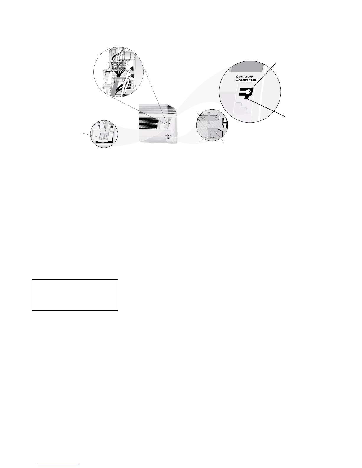
INDOOR UNIT
2 X 09, 2 X 12
Operation push button for
automatic operation (23°C/73°F),
turning the a/c OFF, canceling
the malfunction indication,
and resetting the filter LED.
PLASTIC CONTROL
COVER
Fig. 12A — Indoor unit LED’s and Wiring
FLARING AND CONNECTING REFRIGERANT LINES
1. Remove the protective cap from the flare fitting.
2. Remove the protective cap from the tubing and cut to the
required length. Be sure that the cut is perpendicular and
clean, without burrs.
3. Slip the flare nut on the tubing and flare the tube end using
standard flaring tools.
4. Tighten the nut until resistance is met. Mark the nut and
the fitting. Using a suitable wrench tighten an additional ¼
turn. Use the following specified torque, according to connection size:
Mixed−Phase line: Suction line:
1/4 in.−(12.3 ft−lb.) 1/2 in.−(36 ft−lb.)
Both refrigerant lines need to be insulated separately
NOTE: The service valves on the outdoor unit must remain
closed until all 4 connections have been made.
EVACUATE TUBING AND CHARGE THE SYSTEM —
When all the fittings are connected, air must be expelled, then
refrigerant charge must be checked and adjusted. Follow the steps
below.
1. Open the service port cap on the suction line valve (large
valve of unit No. 1).
2. Connect the vacuum pump to the service port of unit No.
1 via the pressure gage and evacuate to 500 microns to
eliminate contamination and moisture.
OFF ON
IR RECEIVER
TIMER
SERVICE LED
FILTER
3. Disconnect the vacuum pump. Unit should maintain 500
microns for 5 minutes.
4. Remove the service port caps from the mixed−phase valve
and suction line valve
5. Open the mixed−phase valve (small valve) with an Allen
wrench.
6. Open the suction line valve (large valve) with an Allen
wrench.
7. To evacuate and charge unit No. 2 repeat steps 1 thru 6.
8. The outdoor unit is supplied with sufficient R−22 re-
frigerant for up to 25 ft. lineset length. Add 0.9 oz. of
refrigerant for each additional 3 ft. of tubing length.
9. Make sure that the valves are properly opened. Be careful
not to open them more than required as this may damage
the thread.
10. Replace the service port cap. Using refrigerant oil, lubricate the cap beam and hand tighten until resistance is met.
Use a suitable wrench to tighten the cap by an additional
1/2 turn.
Power Supply — See Tables 4 and 5 for electrical data and Fig.
13−14 for system wiring diagrams.
Lea k Te s t — Leak test all fittings with appropriate test
equipment.
10
Page 11

Table 4—Electrical Data, Indoor Units — 30VDC
UNIT
VOLTAGE MCA* MOCP* FULL
LOAD
AMPS
FAN MO-
TOR
AMPS
COM-
PRESSOR
AMPS
COMPRESSOR
LOCKED ROTOR
DFF2AH 09J1A 30VDC N/A N/A 1.8 1.1 N/A N/A
DFF2HH 12J1A 30VDC N/A N/A 1.8 1.5 N/A N/A
LEGEND
MCA - Minimum Circuit Amps
MOCP - Maximum Overcurrent Protection
* If indoor unit is powered from outdoor terminal block, the MOCP for the
outdoor unit is for both sections
NOTE: Specifications and performance data are subject to change with-
out notice.
3095897
Table 5—Electrical Data, Outdoor Units — 115, 1−60
UNIT
VOLTAGE MCA* MOCP* FULL
LOAD
AMPS
DFC2A 318J2A 115VAC 19.8 25 18 1.00 7.2 42
DFC2H 324J2A 115VAC 24.6 30 22.2 1.00 9.3 58
LEGEND
MCA - Minimum Circuit Amps
MOCP - Maximum Overcurrent Protection
* If indoor unit is powered from outdoor terminal block, the MOCP for the
outdoor unit is for both sections.
NOTE: Specifications and performance data are subject to change with-
out notice.
FAN MO-
TOR
AMPS
COM-
PRESSOR
AMPS
COMPRESSOR
LOCKED ROTOR
AMPS
AMPS
3095897
11
Page 12

A-18932520315
pmup taeH margaiD gniriW 21 X 2 / 90 X 2 sledoM
1 BT
G
R
/
Y
E
L
B
L
K
W
H
T
VTLH
KLB
EULB *
RB *
LEY/RG*
NAF
1J
4K
3K
2K
1K
NTR CD
NAF
ESUF
A6
W
H
T
SVR
KLB
SVR
B
R
N
CF
1 PMOC
BT
*
B
L
U
E
PH-AC
COMP 1
CDV03
ylppuS rewoP
RO*
RB 1L
LEY/RG ***
NEERG
NEERG
NEERG***
1
6
5432
376 CAT
draoB yaleR
CA
NI
)+( tuO CD
KLB
***RED
)-( NTR CD
CD
tuO
BT
KLB
KLB
DNG
V.T.L.H
1
2
3
4
5
6
+30 VDC
HLTV
COMP 1
RVS
DC RTN
FAN
2
2
LEY/RG
1L
N
RB *
EULB *
1 BT
G
R
/
Y
E
L
B
L
K
W
H
T
VTLH
KLB
FAN
1J
4K
3K
2K
1K
NTR CD
NAF
ESUF
A6
W
H
T
RVS
KLB
SVR
B
R
N
1 PMOC
*
B
L
U
E
PH-AC
COMP 1
CDV03
ylppuS rewoP
RO*
N
B
L
U
E
RB 1L
LEY/RG ***
NEERG
NEERG
NEERG***
376 CAT
draoB yaleR
CA
NI
)+( tuO CD
KLB
***RED
)-( NTR CD
CD
tuO
BT
KLB
KLB
H.L.T.V
1
2
3
4
5
6
+30 VDC
HLTV
COMP 1
RVS
DC RTN
FAN
1
DNG
DNG
GR/YEL
GR/YEL
NN1L1L
CD
NTR
CD
NTR
T I N U R O O D N I
2HT
HW**
LEY**
NEERG**
DER**
21J
7J6J 8J
NAF
SVR
.PMOC
KLB
81J
DER
6K
5K
1K
2K
REPPETS
ROTOM
EULB
V03+
H
W
8K
9K
7K
11J
1
NAF
3 NAF
2 NAF
41J
KLB
DER
1
3
V21+
V21-
KLB
HW
DER
NEERG
CDLB
ROTOM
1J
5J
1
3
3J
4J
1HT
lortnoc 076 CAT
niaM 176 CAT
draoB
B 276CAT
lortnoC rotoM
M
23
1
LE
Y
LEY/RG
2
3
4
6
5
BT
V.T.L.H
1
R
O
RO**
DNG
3HT
KLB**
T I N U R O O D N I
2HT
HW**
LEY**
NEERG**
DER**
21J
6J7J8J
NAF
SVR
.PMOC
81J
6K
5K
1K
2K
STEPPER
ROTOM
8K
9K
7K
11J
41J
KLB
DER
1
3
V21+
V21-
KLB
HW
DER
NEERG
CDLB
ROTOM
1J
5J
1
3
3J
4J
1HT
lortnoc 076 CAT
niaM 176 CAT
draoB
B 276CAT
lortnoC rotoM
M
123
LEY
LEY/RG
2
3
4
6
5
BT
V.T.L.H
1
RO
RO**
DNG
3HT
KLB**
123456
BLK
W
H
T
B
R
N
R
E
D
B
L
K
Y
E
L
/
G
R
W
H
T
B
R
N
R
E
D
N
A
F
R
O
T
O
M
S
V
R
V
T
L
H
S
V
R
V
T
L
H
G
W
A
6
1
-
*
*
*
G
W
A
4
1
-
*
*
G
W
A
2
1
-
*
G
W
A
8
1
S
E
R
I
W
R
E
H
T
O
L
L
A
e
c
i
l
p
S
-
)
d
e
k
r
a
m
n
U
(
l
a
n
i
m
r
e
T
-
g
n
i
r
i
W
y
r
o
t
c
a
F
g
n
i
r
i
W
l
o
r
t
n
o
C
d
l
e
i
F
g
n
i
r
i
W
r
e
w
o
P
d
l
e
i
F
r
o
t
i
c
a
p
a
C
r
o
s
s
e
r
p
m
o
C
C
C
r
o
s
s
e
r
p
m
o
C
P
M
O
C
r
o
t
i
c
a
p
a
C
n
a
F
C
F
d
n
u
o
r
G
D
N
G
l
o
S
e
v
l
a
V
g
n
i
s
r
e
v
e
R
S
V
d
R
i
o
n
e
e
v
l
a
V
.
p
m
e
T
w
o
L
g
n
i
t
a
e
H
V
T
L
H
k
c
o
l
B
l
a
n
i
m
r
e
T
B
T
C
D
s
s
e
l
h
s
u
r
b
C
D
L
B
r
o
s
n
e
s
r
i
a
n
r
u
t
e
R
1
H
T
r
o
s
n
e
s
l
i
o
c
r
o
o
d
n
I
2
H
T
r
o
s
n
e
s
l
i
o
c
r
o
o
d
t
u
O
3
H
T
D
N
E
G
E
L
N
y
l
p
p
u
S
C
A
n
i
a
M
1
L
C
A
V
5
1
1
K
L
B
3
H
T
K
L
B
3
H
T
2
2
1
1
2
1
C
C
*
B
R
*
B
L
K
*
B
R
*
B
L
U
E
1
.
P
M
O
C
C
S
R
C
C
*
B
L
K
*
B
R
*
B
L
U
E
2
.
P
M
O
C
C
S
R
*
B
R
G
R
/
Y
E
L
R
E
D
+
3
0
V
D
C
B
L
K
D
C
R
T
N
Y
E
L
V
S
P
W
H
T
+
1
2
V
D
C
K
L
B
D
E
R
E
U
L
B
V
0
3
+
H
W
1
N
A
F
3
N
A
F
2N
A
F
T
I
N
U
R
O
O
D
T
U
O
2
2
L
E
Y
/
R
G
1
1
1
t
i
u
c
r
i
c
1
t
i
n
u
r
o
o
d
n
I
-
2
t
i
u
c
r
i
c
2
t
i
n
u
r
o
o
d
n
I
-
1
1
1
2
2
2
1
N
A
F
R
O
T
O
M
C
F
2
5
4
3
2
5
4
3
1
5
4
6
1
2
3
4
5
6
CDV03+DER
KLB
NTR CD
LEY
PSV
CDV21+THW
1
2
3
4
5
1
2
3
4
5
EULB N
1
2
3
4
5
1
2
3
4
5
6
1
2
3
4
5
1
5
4
6
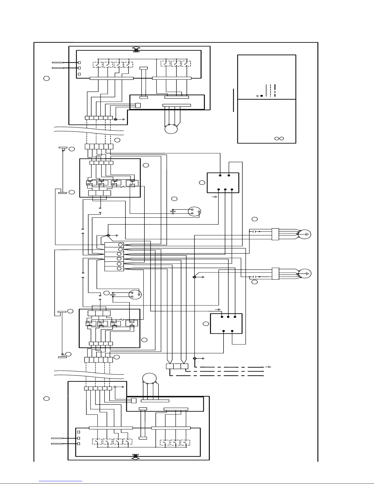
Fig. 13 — System Wiring Schematic DFF2HH09J1A, DFF2HH12J1A FAN COIL WITH DFC2H318J2A, DFC2H324J2A Condensing Unit
12
Page 13
A-28932520315
ylnO gnilooC margaiD gniriW 21 X 2 / 90 X 2 sledoM
1 BT
G
R
/
Y
E
L
B
L
K
W
H
T
VTLH
KLB
EULB *
RB *
LEY/RG*
NAF
1J
4K
3K
2K
1K
NTR CD
NAF
ESUF
A6
W
H
T
SVR
KLB
SVR
B
R
N
CF
1 PMOC
BT
*
B
L
U
E
PH-AC
COMP 1
CDV03
ylppuS rewoP
RO*
RB 1L
LEY/RG ***
NEERG
NEERG
NEERG***
1
6
5432
376 CAT
draoB yaleR
CA
NI
)+( tuO CD
KLB
***RED
)-( NTR CD
CD
tuO
BT
KLB
KLB
DNG
V.T.L.H
1
2
3
4
5
6
+30 VDC
HLTV
COMP 1
RVS
DC RTN
FAN
2
2
LEY/RG
1L
N
RB *
EULB *
1 BT
G
R
/
Y
E
L
B
L
K
W
H
T
VTLH
KLB
FAN
1J
4K
3K
2K
1K
NTR CD
NAF
ESUF
A6
W
H
T
RVS
KLB
SVR
B
R
N
1 PMOC
*
B
L
U
E
PH-AC
COMP 1
CDV03
ylppuS rewoP
RO*
N
B
L
U
E
RB 1L
LEY/RG ***
NEERG
NEERG
NEERG***
376 CAT
draoB yaleR
CA
NI
)+( tuO CD
KLB
***RED
)-( NTR CD
CD
tuO
BT
KLB
KLB
H.L.T.V
1
2
3
4
5
6
+30 VDC
HLTV
COMP 1
RVS
DC RTN
FAN
1
DNG
DNG
GR/YEL
GR/YEL
NN1L1L
CD
NTR
CD
NTR
T I N U R O O D N I
2HT
HW**
NEERG**
DER**
21J
7J6J8J
NAF
SVR
.PMOC
KLB
81J
DER
6K
5K
1K
2K
REPPETS
ROTOM
EULB
V03+
HW
8K
9K
7K
11J
1 NAF
3 NAF
2 NAF
41J
KLB
DER
1
3
V21+
V21-
KLB
HW
DER
NEERG
CDLB
ROTOM
1J
5J
1
3
3J
4J
1HT
lortnoc 076 CAT
niaM 176 CAT
draoB
B 276CAT
lortnoC rotoM
M
2
3
1
LE
Y
LEY/RG
2
3
4
6
5
BT
V.T.L.H
1
RO
DNG
KLB**
T I N U R O O D N I
2HT
HW**
NEERG**
DER**
21J
6J7J8J
NAF
SVR
.PMOC
81J
6K
5K
1K
2K
STEPPER
ROTOM
8K
9K
7K
11J
41J
KLB
DER
1
3
V21+
V21-
KLB
HW
DER
NEERG
CDLB
ROTOM
1J
5J
1
3
3J
4J
1HT
lortnoc 076 CAT
niaM 176 CAT
draoB
B 276CAT
lortnoC rotoM
M
123
LEY
LEY/RG
2
3
4
6
5
BT
V.T.L.H
1
RO
DNG
KLB**
123456
B
L
K
W
H
T
B
R
N
R
E
D
B
L
K
Y
E
L
/
G
R
W
H
T
B
R
N
R
E
D
N
A
F
R
O
T
O
M
G
W
A
6
1
-
*
*
*
G
W
A
4
1
-
*
*
G
W
A
2
1
-
*
G
W
A
8
1
S
E
R
I
W
R
E
H
T
O
L
L
A
e
c
i
l
p
S
-
)
d
e
k
r
a
m
n
U
(
l
a
n
i
m
r
e
T
-
g
n
i
r
i
W
y
r
o
t
c
a
F
g
n
i
r
i
W
l
o
r
t
n
o
C
d
l
e
i
F
g
n
i
r
i
W
r
e
w
o
P
d
l
e
i
F
r
o
t
i
c
a
p
a
C
r
o
s
s
e
r
p
m
o
C
C
C
r
o
s
s
e
r
p
m
o
C
P
M
O
C
r
o
t
i
c
a
p
a
C
n
a
F
C
F
d
n
u
o
r
G
D
N
G
k
c
o
l
B
l
a
n
i
m
r
e
T
B
T
C
D
s
s
e
l
h
s
u
r
b
C
D
L
B
r
o
s
n
e
s
r
i
a
n
r
u
t
e
R
1
H
T
r
o
s
n
e
s
l
i
o
c
r
o
o
d
n
I
2
H
T
D
N
E
G
E
L
N
y
l
p
p
u
S
C
A
n
i
a
M
1
L
C
A
V
5
1
1
K
L
B
K
L
B
2
2
1
1
2
1
C
C
*
B
R
*
B
L
K
*
B
R
*
B
L
U
E
1
.
P
M
O
C
C
S
R
C
C
*
B
L
K
*
B
R
*
B
L
U
E
2
.
P
M
O
C
C
S
R
*
B
R
G
R
/
Y
E
L
R
E
D
+
3
0
V
D
C
B
L
K
D
C
R
T
N
Y
E
L
V
S
P
W
H
T
+
1
2
V
D
C
K
L
B
D
E
R
E
U
L
B
V
0
3
+
H
W
1N
A
F
3
N
A
F
2
N
A
F
T
I
N
U
R
O
O
D
T
U
O
2
2
L
E
Y
/
R
G
1
1
1
t
i
u
c
r
i
c
1
t
i
n
u
r
o
o
d
n
I
-
2
t
i
u
c
r
i
c
2
t
i
n
u
r
o
o
d
n
I
-
1
1
1
2
2
2
1
N
A
F
R
O
T
O
M
C
F
2
5
4
3
2
5
4
3
1
5
4
6
1
2
3
4
5
6
CDV03+DER
KLB
NTR CD
LEY
PSV
CDV21+THW
1
2
3
4
5
1
2
3
4
5
EULB N
1
2
3
4
5
1
2
3
4
5
6
1
2
3
4
5
1
5
4
6
Fig. 14 — System Wiring Schematic DFF2AH09J1A, DFF2AH12J1A FAN COIL WITH DFC2H318J2A, DFC2A324J2A Condensing Unit
13
Page 14
START−UP
System Checks
1. Conceal the tubing where possible.
2. Make sure that the drainage tube slopes downward along
its entire length.
3. Ensure all tubing and connections are properly insulated.
4. Fasten tubes to the outside wall.
5. Seal the hole through which the cables and tubing pass.
6. Connect the air conditioner to the power source and turn it
on.
7. Check all air conditioner operating modes. Refer to Owner’s Manual for operating details.
INDOOR UNIT
1. Do all the remote controller buttons function properly?
2. Do the display panel lights work properly?
3. Does the air deflection louver function properly?
4. Does the drainage work?
OUTDOOR UNIT
1. Are there unusual noises or vibrations during operation?
2. Is noise, drain water or airflow from the unit likely to disturb the neighbors?
3. Are there any gas leaks?
EXPLAIN THE FOLLOWING ITEMS TO THE CUSTOMER,
WITH THE AID OF THE OWNER’S MANUAL:
1. How to turn the air conditioner on and off; selecting cooling, heating and other operating modes; setting a desired
temperature; setting the timer to automatically start and
stop air conditioner operation; and the other features of the
remote controller and display panel.
2. How to remove and clean the air filter.
3. How to set the air deflection louver.
4. Explain care and maintenance.
5. Present the Owner’s Manual and installation instructions
to the customer.
CARE AND MAINTENANCE
The following may be performed by the equipment owner.
Outdoor Units
!
WARNING
dirt and debris from drain holes in base of unit. Fan motors are waterproof.
Indoor Units
!
WARNING
ELECTRICAL SHOCK HAZARD
Failure to follow this warning could result in personal
injury or death.
To avoid the possibility of electric shock, before performing
any cleaning and maintenance operations, always turn off
power to the system by pressing the ON/OFF button on the
remote control and turn off the separate disconnect switch
located near the unit.
If the indoor unit is on a separate switch, be sure to turn this
disconnect off as well.
!
CAUTION
COMPONENT DAMAGE HAZARD
Failure to follow this may result in unit component damage.
Do not wash filter in water over 120_F (to avoid
shrinkage). Do not expose filter to fire (to avoid fire
damage). Do not expose filter to direct sunlight. Clean filter
more frequently when air is extremely dirty.
!
WARNING
ELECTRICAL SHOCK, FIRE COMPONENT DAMAGE
HAZARD
Failure to follow this warning could result in personal
injury, death and or property damage.
Do not attempt to clean or service components in control
box.
To Clean the Indoor Unit Front Panel — if the front panel of
the unit becomes dirty or smudged, wipe the out−side of the panel
with a soft dry cloth. Use a mild liquid deter−gent and wipe off
carefully with a dry cloth.
To Clean Indoor Coil — To clean the coil, remove indoor unit
front panel and vacuum the coil fins, using care not to bend or
damage fins.
LUBRICATION — The indoor−fan, automatic air sweep, and the
outdoor−fan motors are factory lubricated and require no oiling.
Air Filters for Indoor Units
ELECTRICAL SHOCK HAZARD
Failure to follow this warning could result in personal
injury or death.
Before performing recommended maintenance, be sure unit
main power switch is turned off.
CLEANING COILS — Coil should be washed out with
water or blown out with compressed air. Clean coil annually or as required by location and outdoor air conditions. Inspect coil monthly and clean as required. Fins
are not continuous through coil sections. Dirt and debris
may pass through first section, become trapped between
the row of fins and restrict outdoor unit airflow. Use a
flashlight to determine if dirt or debris has collected between coil sections. Clean coil as follows:
1. Turn off unit power and install lockout tag.
2. Using a garden hose or other suitable equipment, flush
coil from the outside to remove dirt. Be sure to flush all
!
CAUTION
COMPONENT DAMAGE HAZARD
Failure to follow this caution may result in unit component
damage.
Operating your system with dirty air filters may damage the
indoor unit and, in addition, can cause reduced
performance, intermittent system operation, frost build up
on the indoor coil, and blown fuses. Inspect and clean or
replace the air filters monthly.
TO REMOVE AIR FILTERS — Open the unit’s front panel by
lifting the lower part and pulling it gently outward and upward.
Pull out the filters.
TO CLEAN OR REPLACE FILTERS — Filters can be
vacuumed or washed in warm water. Shake filter to remove any
excess water, and replace it back. If the filter has begun to break
14
Page 15

down or is torn, replace it. Replacement filters are available
through a local dealer.
SERVICE
The following should be performed by a qualified service
technician.
Clean Condensate Drains — Clean all drains and drain pans at
the start of each cooling season. Check the flow by pouring water
into the drain.
Clean or Replace Drain Pan — The drain pan should only be
cleaned or replaced by a qualified service technician.
1. Place a plastic sheet on the floor to catch any water that
may spill from the drain pan.
2. Remove the intake grille and distribution assembly.
3. Remove the condensate water in the drain pan by letting
water drain into a 3−gallon bucket.
15
Page 16

TROUBLESHOOTING (Tables 6−8, and Fig. 15)
ELECTRICAL SHOCK HAZARD
Failure to follow this warning could result in personal
injury or death.
Be sure to check for broken wires or loose cable lugs before
troubleshooting system.
LAMP STATUS
INDICATION CORRECTION ACTION
1 Flash Faulty TH1 Sensor
2 Flashes Faulty TH2 Sensor
3 Flashes Low Pressure
4 Flashes High Pressure
5 Flashes Low Voltage
6 Flashes High Voltage
!
WARNING
Table 6—Service Indicators
Check the TH1 thermistor for correct resistance.
Check for proper connection.
Replace thermistor if necessary.
Check the TH2 thermistor for correct resistance.
Check for proper connection.
Replace thermistor if necessary.
Check system pressures.
Check refrigerant charges.
Check thermistors (TH1 and TH2) for correct resistance.
Check system pressures.
Check refrigerant charges.
Check thermistors (TH1 and TH2) for correct resistance.
Check operating voltage.
Check electrical connections.
Check operating voltage.
Check electrical connections.
POWER LED.
OFF WHEN SYSTEM IS
OPERATING AND FLASHES
WHEN SYSTEM IS IN ERROR.
(DOES NOT INDICATE ERROR CODE)
CLEAN FILTER INDICATOR
FLASHED AFTER 250 HOURS
OF OPERATION
Fig. 15 — Indicator Lights
16
OPERATION LED.
INDICATES ERROR
Page 17

Table 7—DFS2A/DFS2H Thermistor TH−1, TH−2, and TH−3 Temperature to Resistance Conversion
TEMPERATURE
( F)
−4.0 −20
−2.2 −19
−0.4 −18
1.4 −17
3.2 −16
5.0 −15
6.8 −14
8.6 −13
10.4 −12
12.2 −11
14.0 −10
15.8 −9
17.6 −8
19.4 −7
21.2 −6
23.0 −5
24.8 −4
26.6 −3
28.4 −2
30.2 −1
32.0 0
33.8 1
35.6 2
37.4 3
39.2 4
41.0 5
42.8 6
44.6 7
46.4 8
48.2 9
50.0 10
51.8 11
53.6 12
55.4 13
57.2 14
59.0 15
60.8 16
62.6 17
64.4 18
66.2 19
68.0 20
69.8 21
71.6 22
73.4 23
75.2 24
77.0 25
78.8 26
80.6 27
82.4 28
84.2 29
86.0 30
87.8 31
89.6 32
91.4 33
93.2 34
NOTE: Resistance tolerance ± 3%.
TEMPERATURE
( C)
TEMPERATURE
TOLERANCE
( F)
TEMPERATURE
TOLERANCE
( C)
MINIMUM
RESISTANCE
(KW)
MEAN
RESISTANCE
(KW)
±2.0 ±1.1 30.89 32.44 34.05
±2.0 ±1.1 29.46 30.93 32.45
±2.0 ±1.1 28.12 29.51 30.94
±2.0 ±1.1 26.84 28.16 29.51
±2.0 ±1.1 25.64 26.88 28.15
±2.0 ±1.1 24.49 25.66 26.87
±2.0 ±1.1 23.40 24.52 25.66
±2.0 ±1.1 22.38 23.43 24.50
±2.0 ±1.1 21.40 22.39 23.41
±2.0 ±1.1 20.47 21.41 22.38
±1.8 ±1.0 19.59 20.48 21.40
±1.8 ±1.0 18.74 19.59 20.45
±1.8 ±1.0 17.94 18.74 19.56
±1.8 ±1.0 17.17 17.93 18.71
±1.8 ±1.0 16.44 17.16 17.90
±1.8 ±1.0 15.75 16.43 17.13
±1.8 ±1.0 15.10 15.74 16.40
±1.8 ±1.0 14.47 15.08 15.71
±1.8 ±1.0 13.87 14.46 15.05
±1.8 ±1.0 13.31 13.86 14.42
±1.8 ±1.0 12.77 13.29 13.83
±1.8 ±1.0 12.25 12.74 13.25
±1.8 ±1.0 11.75 12.22 12.70
±1.8 ±1.0 11.28 11.73 12.18
±1.8 ±1.0 10.83 11.25 11.68
±1.8 ±1.0 10.40 10.80 11.21
±1.8 ±1.0 9.986 10.370 10.76
±1.8 ±1.0 9.595 9.960 10.33
±1.8 ±1.0 9.222 9.569 9.921
±1.8 ±1.0 8.866 9.196 9.530
±1.8 ±1.0 8.526 8.840 9.157
±1.8 ±1.0 8.197 8.496 8.797
±1.8 ±1.0 7.883 8.167 8.453
±1.6 ±0.9 7.583 7.853 8.125
±1.6 ±0.9 7.296 7.553 7.812
±1.6 ±0.9 7.022 7.267 7.513
±1.6 ±0.9 6.761 6.993 7.227
±1.6 ±0.9 6.510 6.731 6.954
±1.6 ±0.9 6.271 6.481 6.693
±1.6 ±0.9 6.042 6.242 6.444
±1.6 ±0.9 5.822 6.013 6.205
±1.6 ±0.9 5.611 5.793 5.975
±1.6 ±0.9 5.408 5.581 5.755
±1.6 ±0.9 5.214 5.379 5.544
±1.6 ±0.9 5.028 5.185 5.343
±1.6 ±0.9 4.850 5.000 5.150
±1.6 ±0.9 4.675 4.821 4.968
±1.6 ±0.9 4.508 4.650 4.793
±1.6 ±0.9 4.347 4.486 4.626
±1.8 ±1.0 4.193 4.329 4.466
±1.8 ±1.0 4.046 4.179 4.312
±1.8 ±1.0 3.904 4.033 4.163
±1.8 ±1.0 3.767 3.894 4.020
±1.8 ±1.0 3.637 3.760 3.884
±1.8 ±1.0 3.511 3.631 3.752
MAXIMUM
RESISTANCE
(KW)
17
Page 18

Table 7 —DFS2A/DFS2H Thermistor TH−1, TH−2, and TH−3 Temperature to Resistance Conversion (Cont.)
TEMPERATURE
( F)
95.0 35
96.8 36
98.6 37
100.4 38
102.2 39
104.0 40
105.8 41
107.6 42
109.4 43
111.2 44
113.0 45
114.8 46
116.6 47
118.4 48
120.2 49
122.0 50
123.8 51
125.6 52
127.4 53
129.2 54
131.0 55
132.8 56
134.6 57
136.4 58
138.2 59
140.0 60
141.8 61
143.6 62
145.4 63
147.2 64
149.0 65
150.8 66
152.6 67
154.4 68
156.2 69
158.0 70
TEMPERATURE
( C)
NOTE: Resistance tolerance ± 3%.
TEMPERATURE
TOLERANCE
( F)
TEMPERATURE
TOLERANCE
( C)
MINIMUM
RESISTANCE
(KW)
MEAN
RESISTANCE
(KW)
±1.8 ±1.0 3.391 3.508 3.626
±2.0 ±1.1 3.275 3.390 3.505
±2.0 ±1.1 3.164 3.276 3.389
±2.0 ±1.1 3.058 3.167 3.277
±2.0 ±1.1 2.956 3.062 3.169
±2.0 ±1.1 2.857 2.961 3.066
±2.0 ±1.1 2.762 2.864 2.966
±2.0 ±1.1 2.671 2.770 2.870
±2.2 ±1.2 2.583 2.679 2.777
±2.2 ±1.2 2.498 2.593 2.688
±2.2 ±1.2 2.417 2.509 2.602
±2.2 ±1.2 2.339 2.429 2.520
±2.2 ±1.2 2.264 2.352 2.441
±2.3 ±1.3 2.192 2.227 2.364
±2.3 ±1.3 2.122 2.206 2.291
±2.3 ±1.3 2.055 2.137 2.220
±2.3 ±1.3 1.990 2.070 2.151
±2.3 ±1.3 1.928 2.006 2.085
±2.3 ±1.3 1.867 1.943 2.021
±2.3 ±1.3 1.809 1.883 1.959
±2.5 ±1.4 1.753 1.826 1.900
±2.5 ±1.4 1.699 1.770 1.842
±2.5 ±1.4 1.647 1.717 1.787
±2.5 ±1.4 1.597 1.665 1.734
±2.5 ±1.4 1.549 1.615 1.683
±2.5 ±1.4 1.503 1.567 1.633
±2.7 ±1.5 1.458 1.521 1.585
±2.7 ±1.5 1.414 1.476 1.539
±2.7 ±1.5 1.372 1.432 1.494
±2.7 ±1.5 1.332 1.391 1.451
±2.7 ±1.5 1.293 1.350 1.409
±2.9 ±1.6 1.255 1.311 1.369
±2.9 ±1.6 1.219 1.274 1.330
±2.9 ±1.6 1.184 1.237 1.292
±2.9 ±1.6 1.150 1.202 1.256
±2.9 ±1.6 1.117 1.168 1.221
MAXIMUM
RESISTANCE
(KW)
18
Page 19

Table 8—General System Troubleshooting Guide
SYMPTOM
Unit Fails to Start. Power supply from outdoor unit to indoor unit is
Only Indoor Fan Works
when Cooling or Heating is Desired. NOTE:
Indoor fan runs continuously in cooling mode.
Only Indoor Fan Motor
and Outdoor Fan Motor
are Working. No Cooling and/or Heating
Takes Place.
No Air Supply at Indoor
Unit (Compressor Operates).
Low Capacity. Lack of refrigerant. Ice formation on the evapora-
In Heat Mode, Only
Compressor Runs. Outdoor and Indoor Fan
Motors are Stopped.
Water Accumulates
and Overflows from
Evaporator Drain Pan.
Unit Does Not Operate
in Desired Mode.
not connected.
Power supply to unit not connected (POWER
LED Off).
Fuse blown (POWER LED Off). Reset circuit breaker or replace line fuse.
ON/SEND button has not been pressed. Press ON/SEND button on remote control.
Indoor unit does not receive transmitted commands.
The selected mode is Fan Only, or Cool when
heating is desired.
Temperature is set to a value which is too high (in
Cool mode).
Overload safety device on compressor is cut out
due to high temperature.
Compressor run capacitor is burnt. Replace compressor run capacitor.
Compressor winding shorted. Replace compressor.
Indoor fan motor is blocked or turns slowly. 1. Check voltage. Repair wiring if necessary.
Indoor fan motor capacitor is burnt. Replace indoor fan motor capacitor.
Indoor fan motor winding is burnt. Replace indoor fan motor.
In Heat mode: Delayed start for indoor fan motor. Normal software delay (maximum of 20 sec).
Clogged air filters. Clean filters.
tor coil.
Clogged air filters. Clean filters.
A/C operating in defrost cycle. Wait 10 minutes (maximum) until the unit resumes normal opera-
Drain pan pipe or hose is clogged or the spout of
drain pan is clogged.
The unit is in the Auto, (emergency) mode. Push button once to cancel Auto, (emergency) mode.
Faulty remote control settings. 1. If remote control symbols respond to the commands correctly,
PROBABLE CAUSE CORRECTIVE ACTION
Check for proper connection of power at disconnect.
Make sure that nothing is blocking the remote control transmission to the unit.
Check if the remote control is in the desired mode. If not, select
the correct mode (refer to User manual). Also note that every 15
minutes (maximum) the compressor will be switched minimally
on for 3 minutes.
Observe the temperature setting on the remote control. Also note
that each 15 minutes (maximum), the compressor will be
switched on minimally for 3 minutes.
Switch off power and try again after one hour.
2. Check indoor fan wheel if tight on motor shaft. Tighten if necessary.
Unit must be charged (according to the nameplate) after localizing the gas leak.
tion.
Disassemble plastic drain pipe from spout of evaporator drain
pan. Flush with clean water.
check the unit ID Code (Standard or Alternative). Refer to
“Changing Unit ID Code” in the Owner’s Manual.
Remote control low battery. Replace remote control batteries.
The Unit Receives Interference from Other Remote Control or the Remote Control Interferes
with Other Instruments.
Common Infrared Code. Modify the Remote Control IR transmission code.
IMPORTANT:
The units are designed to work in heat mode only down to −10_C (14_F) outdoor ambient temperature.
If at starting time outdoor temperature is equal or lower than −10_C (14_F) the unit will not start and the filter led will flash five
(5) times to indicate that low temperature protection is activated.
Manufacturer reserves the right to discontinue, or change at any time, specifications or designs without notice and without incurring obligations.
2. If Cool commands are OK, but Heat symbol is skipped on
LCD, refer to setting the remote to cooling or heat pump on the
Owner’s Manual.
3. Replace remote control.
Refer to “Changing Unit ID Code” in the Owner’s Manual.
International Comfort Products, LLC
Lewisburg, Tennessee 37091
19
 Loading...