

International comfort products DFS2A318J2A, DFS2A324J2A, DFS2H318J2A, DFS2H324J2A Installation, Start-up And Service Instructions Manual
Cooling Model
DFS2A318J2A
DFS2A324J2A
Heat Pump
DFS2H318J2A
DFS2H324J2A
Installation, Start-Up, and Service Instructions
CONTENTS SAFETY CONSIDERATIONS
SAFETY CONSIDERATIONS ...................... 1
GENERAL ..................................... 1-7
INSTALLATION .............................. 7-14
Indoor Unit Installation ........................ 7
Outdoor Unit Installation ........................ 9
Power Supply ................................ 10
Leak Test ..................................... 10
Wiring Diagrams ........................... 12-13
START-UP .................................... 14
System Checks ................................ 14
CARE AND MAINTENANCE ....................... 14
Outdoor Units ................................. 14
Indoor Units ................................... 14
To Clean the Indoor Unit Front Panel ............ 14
To Clean Indoor Coil ........................... 14
Air Filters for Indoor Units ...................... 14
SERVICE ....................................... 15
TROUBLESHOOTING ........................ 16-19
Page
421 01 9219 00 I
Installing, starting up, and servicing air-conditioning equipment
can be hazardous due to system pressures, electrical components,
and equipment location (roofs, elevated structures, etc.).
Only trained, qualified installers and service mechanics should
install, start-up, and service this equipment.
Untrained personnel can perform basic maintenance functions
such as cleaning coils. All other operations should be performed
by trained service personnel.
When working on the equipment, observe precautions in the
literature mid on tags, stickers, mid labels attached to the equipment.
Follow all safety codes. Wear safety glasses and work gloves.
Keep quenching cloth and fire extinguisher nearby when brazing.
Use care in handling, rigging, and setting bulky equipment.
51302618919-B NOV 06
DFS2A/H 2X09, 2X12
Duct Free Systems
Safety Labeling and Signal Words
DANGER, WARNING, CAUTION, and
NOTE
The signal words DANGER, WARNING, CAUTION, and
NOTE are used to identifylevels of hazard serious-
ness. The signal word DANGER is only used on
product labels to signify an immediate hazard. The
signal words WARNING, CAUTION, and NOTE will
be used on product labels and throughout this manu-
al and other manuals that may apply to the product.
DANGER - immediate hazards which will result in se-
vere personal injury or death.
WARNING - Hazards or unsafe practices which could
result in severe personal injuryor death.
CAUTION - Hazards or unsafe practices which may re-
sult in minor personal injury or product or property
damage.
NOTE - Used to highlight suggestions which will result in
enhanced installation, reliability, or operation.
ELECTRICAL SHOCK HAZARD
Failure to follow this warning could result in personal
injury or death.
Before installing or servicing system, always turn off main
power to system and install lockout tag on disconnect.
There mav be more than one disconnect switch.
Signal Words in Manuals
The signal word WARNING is used throughout this
manual in the following manner:
The signal word CAUTION is used throughout this
manual in the following manner:
Signal Words on Product Labeling
Signal words are used in combination with colors and/or
pictures on product labels.
GENERAL
These instructions cover the installation, start-up and servicing of
DFC2A/DFC2H outdoor and DFF2A/DFF2H indoor units
cooling only and heat pump duct free systems. See Table 1 for
parts included. See Tables 2 and 3 for Physical Data.
SYSTEM REQUIREMENTS
IMPORTANT: The Indoor units & the inter units cable voltage
is 30 VDC.
IMPORTANT: Each refrigerant line must be insulated
Separately. See line sizing requirements in able 2.
• Consult local building codes and National Electrical Code
(NEC, U.S.A.) for special installation requirements.
Max. cable length. Total voltage drop should not exceed
1V. Therefore max. length:
For #18 AWG 24.3 Feet (7.4 m)
For #16 AWG 37.7 Feet (11.5 m)
For #14 AWG 50.0 Feet (18 111)
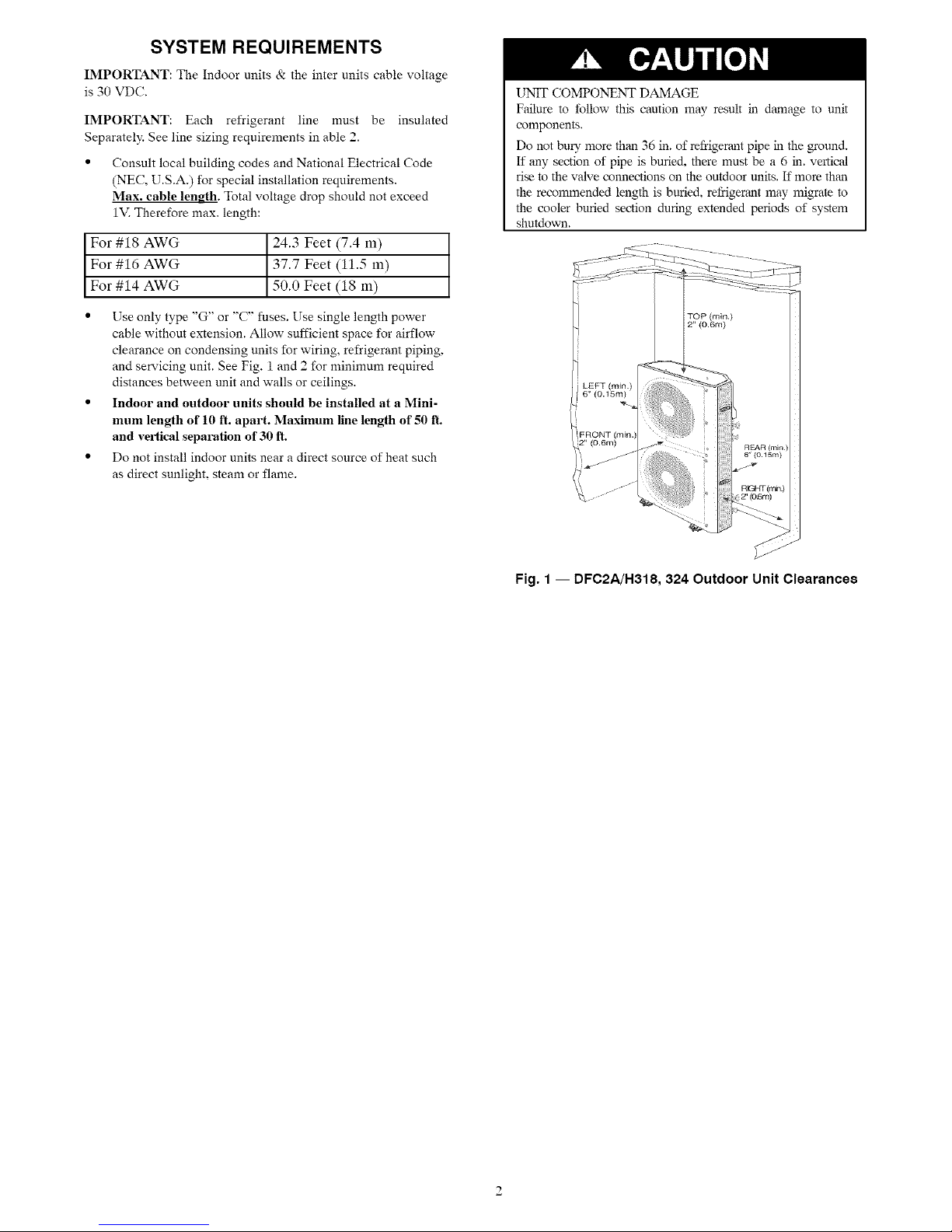
• Use only type "G" or "C" fuses. Use single length power
cable without extension. Allow sufficient space for airflow
clearance on condensing units for wiring, refrigerant piping,
and servicing unit. See Fig. 1 and 2 for minimum required
distances between unit and walls or ceilings.
• Indoor and outdoor units should be installed at a Mini-
mum length of 10 ft. apart. Maximum line length of 50 ft.
and veltical separation of 30 ft.
• Do not install indoor units near a direct source of heat such
as direct sunlight, steam or flame.
UNTF COMPONENT DAMAGE
Failure to follow this caution may result in damage to unit
components.
Do not bu_ more than 36 in. of refrigerant pipe in the ground.
If any section of pipe is buried, there must be a 6 in. vertical
rise to the valve connections on the outdoor units. If more than
the recommended length is buried, refrigerant may migrate to
the cooler buried section duNlg extended periods of system
shutdown.
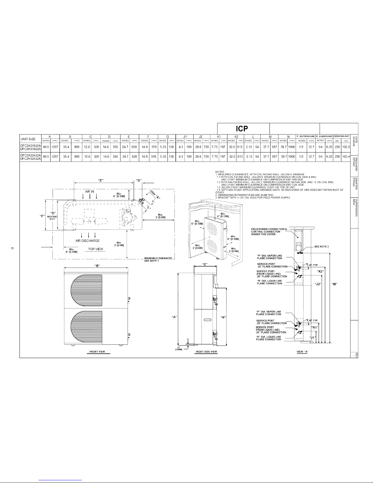
Fig, 1 -- DFC2A/H318, 324 Outdoor Unit Clearances
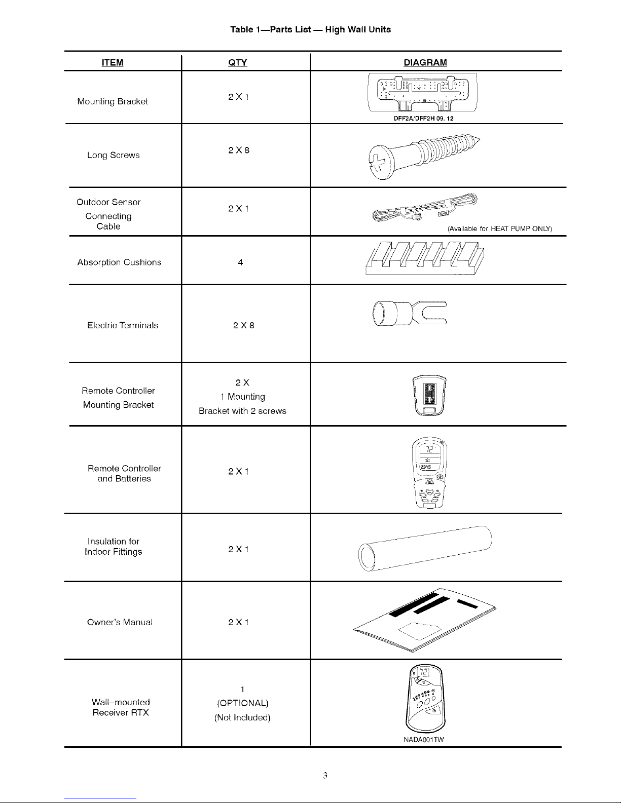
Table 1--Parts List -- High Wall Units
ITEM QTY
Mounting Bracket
Long Screws
Outdoor Sensor
Connecting
Cable
Absorption Cushions
Electric Terminals
DIAGRAM
2X1
DFF2A/DFF2H 09, 12
2X8
2X1
(Available for HEAT PUMP ONLY)
2X8
Remote Controller
Mounting Bracket
Remote Controller
and Batteries
Insulation for
Indoor Fittings
Owner's Manual
2X
1 Mounting
Bracket with 2 screws
2X1
2X1
2X1
Wall-mounted
Receiver RTX
(OPTIONAL)
(Not Included)
NADA001TW
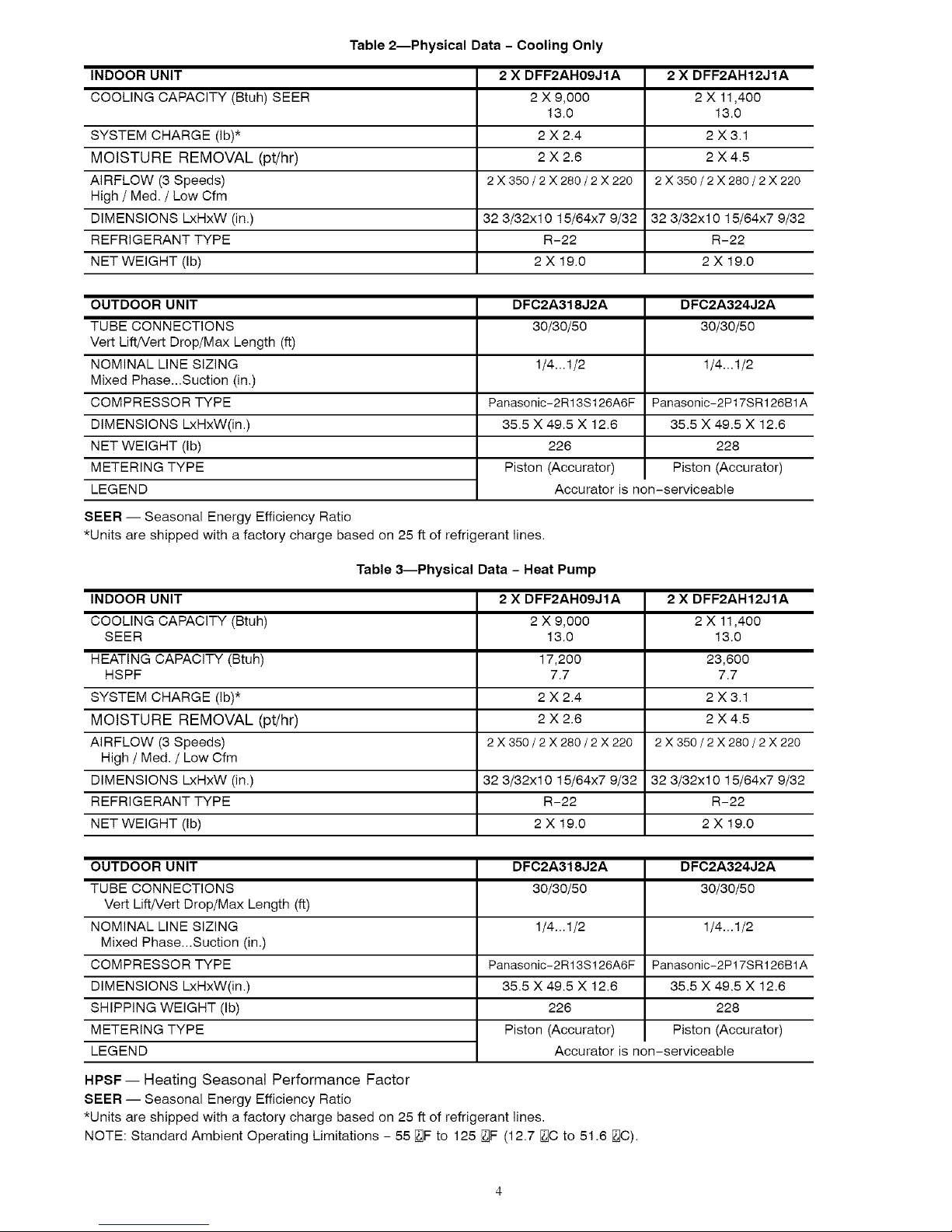
Table 2--Physical Data - Cooling Only
INDOOR UNIT 2 X DFF2AH12JIA
COOLING CAPACITY (Btuh) SEER 2 X 11,400
SYSTEM CHARGE (Ib)* 2 X 3.1
MOISTURE REMOVAL (pt/hr) 2 X 4.5
AIRFLOW (3 Speeds) 2 X 350 / 2 X 280 / 2 X 220
High / Med. / Low Cfm
DIMENSIONS LxHxW (in.) 32 3/32x10 15/64x7 9/32 32 3/32x10 15/64x7 9/32
REFRIGERANT TYPE R-22 R-22
NET WEIGHT (Ib) 2 X 19.0 2 X 19.0
OUTDOOR UNIT
TUBE CONNECTIONS
Vert Lift/Vert Drop/Max Length (ft)
NOMINAL LINE SIZING
Mixed Phase...Suction (in.)
COMPRESSOR TYPE
DIMENSIONS LxHxW(in.)
NET WEIGHT (Ib)
METERING TYPE
LEGEND
2 X DFF2AH09JIA
2 X 9,000
13.0
2X2.4
2X2.6
2X350/2X280/2X220
DFC2A318J2A DFC2A324J2A
30/30/50 30/30/50
1/4...1/2 1/4...1/2
Panasonic-2R13S126A6F Panasonic-2P17SR126B1A
35.5 X 49.5 X 12.6 35.5 X 49.5 X 12.6
226 228
Piston (Accurator) Piston (Accurator)
Accurator is non-serviceable
13.0
SEER -- Seasonal Energy Efficiency Ratio
*Units are shipped with a factory charge based on 25 ft of refrigerant lines.
Table 3_Physical Data - Heat Pump
INDOOR UNIT 2 X DFF2AH09JIA 2 X DFF2AH12JIA
COOLING CAPACITY (Btuh) 2 X 9,000 2 X 11,400
SEER 13.0 13.0
HEATING CAPACITY (Btuh) 17,200 23,600
HSPF 7.7 7.7
SYSTEM CHARGE (Ib)* 2 X 2.4 2 X 3.1
MOISTURE REMOVAL (pt/hr) 2 X 2.6 2 X 4.5
AIRFLOW (3 Speeds) 2 X 350/2 X 280/2 X 220 2 X 350/2 X 280/2 X 220
High / Med. / Low Cfm
DIMENSIONS LxHxW (in.) 32 3/32x10 15/64x7 9/32 32 3/32x10 15/64x7 9/32
REFRIGERANT TYPE R-22 R-22
NET WEIGHT (Ib) 2 X 19.0 2 X 19.0
OUTDOOR UNIT
TUBE CONNECTIONS
Vert Lift/Vert Drop/Max Length (ft)
NOMINAL LINE SIZING
Mixed Phase...Suction (in.)
COMPRESSOR TYPE
DIMENSIONS LxHxW(in.)
SHIPPING WEIGHT (Ib)
METERING TYPE
LEGEND Accurator is non-serviceable
DFC2A318J2A DFC2A324J2A
30/30/50 30/30/50
1/4...1/2 1/4...1/2
Panasonic-2R13S126A6F Panasonic-2P17SR126B1A
35.5 X 49.5 X 12.6 35.5 X 49.5 X 12.6
226 228
Piston (Accurator) Piston (Accurator)
HPSF -- Heating Seasonal Performance Factor
SEER -- Seasonal Energy Efficiency Ratio
*Units are shipped with a factory charge based on 25 ft of refrigerant lines,
NOTE: Standard Ambient Operating Limitations - 55 [_F to 125 0F (12.7 [_C to 51.6 [_C).
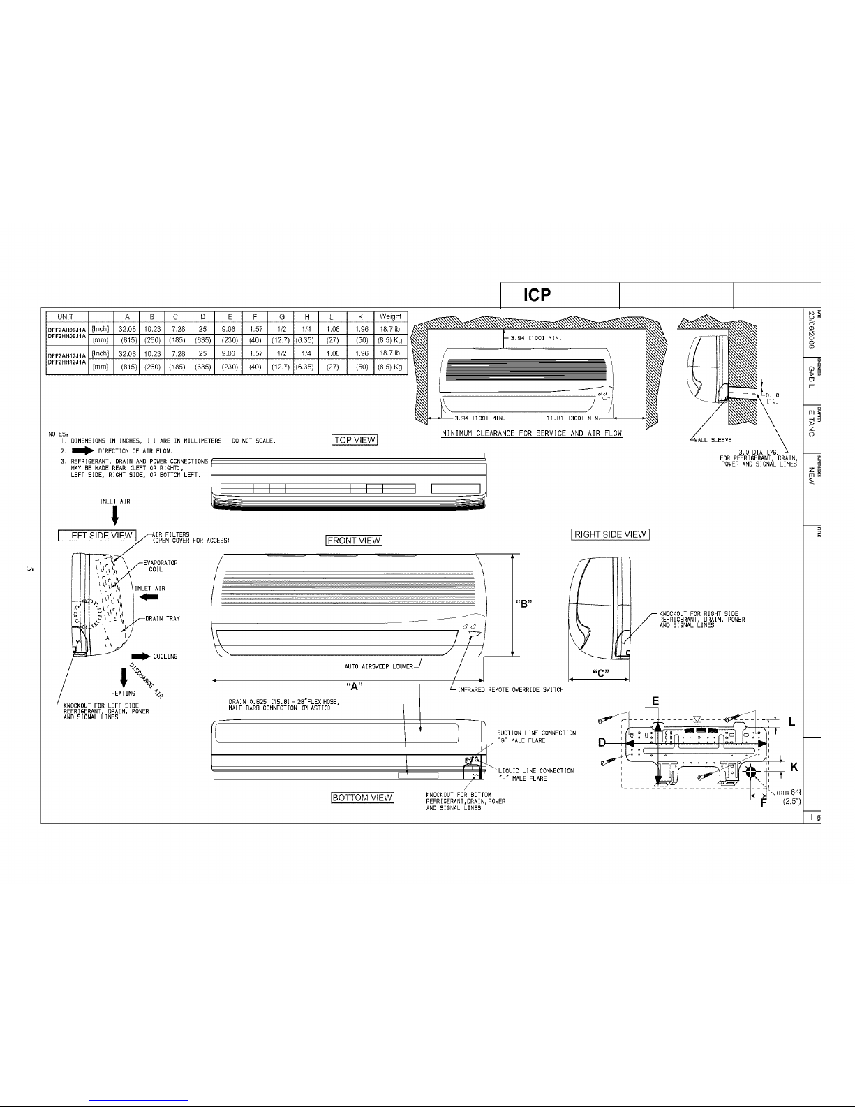
NOTES:
ICP
I. DIMENSIONS IN INCHES, [ ] ARE IN MILLIMETERS - DO NOT SCALE.
2, _ DIRECTION OF AIR FLOW.
3, REFRIGERANT, DRAIN AND POWERCONNECTIONS
MAY BE MADEREAR (LEFT OR RIGHT),
LEFT SIDE, RIGHT SIDE, OR BOTTOMLEFT.
[TOP VIEW]
- 3.94 [I00] MIN.
/ \
/
4
[I00] MIN. 11.81 [300] MIN.
MINIMUM CLEARANCE FOR SERVICE AND AIR FLOW
E
INLET AIR
I
F
I I I I I I I I I I I
[ LEFTSIDEVIEW
F]LTERS
(OPEN COVER FOR ACCESS)
IFRONTVIEWI
IRIGHT SIDE VIEW J
3.0 DIA [76] A
FOR REFRIGERANT, DRAIN,
POWERAND SIGNAL LINES
-EVAPORATOR
COIL
INLET AIR
I_ COOLING
IN
BEAF_NG%
NOCKOUT FOR LEFT SIDE
REFRIGERANT, DRAIN, POWER
AND SIGNAL LINES
f
IIIIAIRS_II
"A" LINFRARE[ REMOTEOVERRIDE SWITCH
DRAIN 0.625 [15.B] - 2B'FLEX BOSE,
MALE BARB CONNECTION (PLASTIC)
[BOTTOM VIEW]
i SUCTION LINE CONNECTION
"G" MALE FLARE
A
I_L_
I' _ J rJ L_OU_OUNECONNECTION
"H" MALE FLARE
,/
KNOCKOUTFOR BOTTOM
REFRIGERANT,DRAIN,POWER
AND SIGNAL LINES
KNOCKOUT FOR RIGHT SIDE
REFRIGERANT, DRAIN, POWER
lAND SIGNAL LINES
E
1
o
o
m
r-
m
z
0
=
m
m
I A I B E C I D I E I F I G I Ji I J2 I
UNIT SIZE
DFC2A318J2AI 4_n I 43 ln_ t _gR 796177F
DFC2A324J2AI49_36 I 4.3 t69 I 28.6 Z261 7.7_
DFC2H324J2A " "
ICP
,971 I 641 ,410, 612261 0 ,
oi ,;
i
I _ w
I '
AIR DISCHARGE
Mim TOP VIEW
6" [0,15M]
Min.
2' [0.6M]
,,g _,
/
LM MJ
FRONT VIEW
MINIMUM CLEARANCE_
SEE NOTE 1
"A"
1
0.7
[18MM] --
NOTES:
1 REQUIRED CLEARANCES, WITH COIL FACING WALL -ALLOW 6 MINIMUM
1 1 WITH COIL FACING WALL - ALLOW 6 MINIMUM CLEARANCE ON COiL SIDE & END
AND 2 FEET MINIMUM CLEARANCE ON COMPRESSOR END FAN SIDE
12 WITH FAN FACING WALL -ALLOW 2 MINIMUM CLEARANCE ON FAN SIDE AND 6 ON COIL END,
AND 2 FEET MINIMUM CLEARANCE ON COMPRESSOR END COiL SIDE
13 ALLOW 2 FEET MINIMUM CLEARANCE OVER THE TOP OF UNIT
14 WITH MULTI-UNITAPPUCATtON, ARRANGE UNITS SO DISCHARGE OF ONE DOES NOT ENTER INLET OF
OTHER
2 DIMENSIONS iN PARENTHESIS ARE IN METRIC
3 BRACKET WITH 1 125 DiA HOLE FOR FIELD POWER SUPPLY
FIELD POWER CONNECTION &
CONTROL CONNECTION
UNDER THIS COVER
"P' DIA. VAPOR LINE ::
FLARESERVICECONNECTIONPORT N _ _
.25" FLARE CONNECTION _ 31
SERVICE PORT _.
(FROM LIQUID LINE) _1_ t
.25" FLARE CONNECTION_ _/_t_i "-_
"R" DIA. LIQUID LINE __
FLARE CONNECTION : ---1
P" DIA. VAPOR LINE
FLARE CONNECTION
SERVICE PORT 31
25' FLARE CONNECTION _
SERVICE PORT
(FROM LIQUID LINE)
.25" FLARE CONNECTION
"R" DIA. LIQUID LINE __ .
FLARE CONNECTION
-- SEE NOTE 3
°TYP
"K2"
"J2 .... M"
=TYP
"KI"
VIEW '_A'_
_EJ
_>
o-I
_m
o
o_
m
mcm
;0
Zoo
mc
co
m
o
m
co
, rn
<
 Loading...