

Page 1

Compliance Statement Insert
Device Name: Hand-held Computer Model Number: 6400
The responsible party for the compliance of this device is: Intermec Technologies Corporation
Norand Mobile System Division
550 Second Street SE
Cedar Rapids, Iowa 52401 USA
(319) 369-3100
CAUTION: See users guide instructions for handling, charging, and replacing batteries. Failure to follow those instructions can result in
personal injury, fire, or battery explosion.
This product complies to the following approvals. The user(s) of this product are cautioned to use accessories and peripherals approved by
Norand Corporation. The use of accessories other than those recommended or changes to this product that are not approved by Norand
Corporation may void the compliance of this product and may result in the loss of the users authority to operate the equipment.
FCC Digital Emissions Compliance
This equipment has been tested and found to comply with the limits for a Class B digital device, pursuant to Part 15 of the FCC Rules. These limits are designed to
provide reasonable protection against harmful interference in a residential installation. This equipment generates, uses and can radiate radio frequency energy and, if not
installed and used in accordance with the instructions, may cause harmful interference to radio communications. However, there is no guarantee that interference will not
occur in a particular installation. If this equipment does cause harmful interference to radio or television reception, which can be determined by turning the equipment off
and on, the user is encouraged to try to correct the interference by one or more of the following measures:
• Reorient or relocate the radio of television receiving antenna.
• Increase the separation between the computer equipment and receiver.
• Connect the equipment into an outlet on a circuit different from that to which the radio or television receiver is connected.
• Consult the dealer or an experienced radio television technician for help.
Canadian Digital Apparatus Compliance
This Class B digital apparatus meets all requirements of the Canadian Interference-Causing Equipment Regulations.
Cet appareil numérique de la classe B respecte toutes les exigences du Règlement sur le matériel brouilleur du Canada.
FCC Spread Spectrum Transmitter Compliance
This device is also certified to operate under Part 15, Subpart C, Section 15.247 of the FCC rules for Intentional Radiation Products. This certification includes Docket
87-389 covering rules effective June 1994. It may not cause interference to authorized radio communication devices, and must accept any interference caused by those
devices.
Canadian RSS-210 Spread Spectrum Transmitter Compliance
Operation is subject to the following two conditions: (1) this device may not cause interference, and (2) this device must accept any interference, including interference
that may cause undesired operation of the device.
Canadian 2.4 GHz Spread Spectrum Radio Certification
This device requires a radio license, unless it is installed totally inside a building. (User’s must obtain this license.)
Une license radio est requise oour ces dispositifs, sauf ouor ceux installés tout á fait á l’intérieur d’un bâtiment. (Il faut que l’utilisateur obtienne cette license.)
Antenna Requirements
FCC rules section 15.203 and Canada RSS-210 require that this device be operated using an antenna furnished by Norand Corporation. The antenna coupling on this
product has been designed to accept only antennas manufactured Norand. Use of an antenna other than that furnished with the equipment is prohibited by FCC and
Industry Canada rules.
European Notice
The 902-928 MHz Spread Spectrum Transmission (SST) radio referred to within this manual is not available for sale in Europe (including, but not limited to, Great
Britain, Italy, Germany, France, Spain, Norway, Denmark, Sweden, Finland, Portugal, and the Benelux countries). Any references in this manual to 902-928 MHz SST, or
modules containing 902-928 MHz SST radios, should be disregarded by the users of this product in Europe.
578-100-008 Revision B Page 1 of 3
Page 2

DECLARATION OF CONFORMITY
(According to ISO/IEC Guide 22 and EN 45014)
PAGE ONE OF TWO
THE PRODUCT HEREWITH COMPLIES WITH THE REQUIREMENTS OF :
THE LOW-VOLTAGE DIRECTIVE 72/32/EEC.
THE EMC DIRECTIVE 89/336/EEC.
Manufacturer’s Name: European Representative:
Intermec Technologies Corporation Intermec International Incorporated
550 2nd Street SE Sovereign House, Vastern Road
Cedar Rapids, Iowa 52401 Reading, Berkshire
RG1 8BT England
Declares that the product listed below:
Product Type: ITE/Residential, Commercial, and Light Industrial
Product Name: 6400 Hand-held Computer with all docking options
Model Number: 6400 Product Options: All
Beginning Serial Number: All Date Issued: April. 8, 1996
Conforms to the following product specifications:
Safety: IEC 950 / EN 60950
EMC: EN 55022 : 1995 / CISPR Publications 22 : 1993, Class B Limits and Methods
EN 50082-1 : 1992 Generic Immunity Standard
IEC 801-2 Tested per IEC 1000-4-2 : 1995-01
8 kV Air / 4 kV Direct, Criteria B
IEC 801-3 Tested per IEC 1000-4-3 : 1995-02
3 V/M, 27-1000 MHz, 80% @ 1kHz, Criteria A
IEC 801-4 Tested per IEC 1000-4-4 : 1995-01
Power leads 2 kV, Signal leads 1 kV, Criteria B
ETS 300 339 : Jun. 1993 Draft RES Generic EMC for radio equipments
IEC 801-2 per Draft prETS 300 339, Clause 9.2
+ 8 kV Air / + 4 kV Contact
IEC 801-3 per Draft prETS 300 339, Clause 9.1
3 V/M, 80-1000 MHz, 80% @ 400 Hz
Type Approval Certification(s): see second page of Declaration of Conformity
I, the undersigned, hereby declare that the equipment specified above conforms the above Directive(s) and
Standard(s).
Company Official: Arvin Danielson Position: Vice President
Signature: Signed Copy on File Date: August 4, 1998
European Contact: Scott Mercer, Intermec International Incorporated, Sovereign House, Vastern Road, Reading,
Berkshire, RG1 8BT England; Phone INT+44 118 987 9400; Fax INT+ 44 118 987 9401
578-100-008 Revision B Page 2 of 3
Page 3

DECLARATION OF CONFORMITY
PAGE TWO OF TWO
Product Type: ITE/Residential, Commercial, and Light Industrial
Product Name: Hand-held Computer Model Number: 6400
Product Option: RM180
Type Approval Certifications:
ARGENTINA: FCC ID: EHARM24002PC AUSTRALIA: FCC ID: EHARM24002PC
AUSTRIA: CEPT-RLAN A BRAZIL: FCC ID: EHARM24002PC
CANADA: Canada 1008 101 760A CHILE: FCC ID: EHARM24002PC
COLOMBIA: FCC ID: EHARM24002PC COSTA RICA: FCC ID: EHARM24002PC
DENMARK: CEPT/RLAN/DK/9608 FINLAND: Label added in Finland
FRANCE: 960182PP0 GERMANY: G128682H
GREECE: БСЧЙКБ ЕЛЕГЧПМЕНЗ УХУКЕХЗ HONG KONG: FCC ID: EHARM24002PC
ICELAND: CEPT-RLAN IS-2433-02 INDIA: FCC ID: EHARM24002PC
ITALY: (For 41-key terminal) (For 51-key terminal)
KOREA: Radio Type Registration MEXICO: SCýT: RCPNORM97-308
NETHERLANDS: ministerie van verkeer waterstaat NORWAY: CEPT-RLAN N
PERU: FCC ID: EHARM24002PC POLAND: M£
SINGAPORE: TAC No. PMREQ-WLAN-B-0621-98 SPAIN: E D.G.Tel 06 97 0340
SWEDEN: Godkaend av Post- och Telestyrelsen TAIWAN: 85G0069
TURKEY: FCC ID: EHARM24002PC UNITED KINGDOM: CEPT-RLAN GB
UNITED STATES: FCC ID: EHARM24002PC VENEZUELA: FCC ID: EHARM24002PC
ЧСЗУЗ:МЕФБЦПСБУ ДЕДПМЕНЩН
'Егксйуз Кхклпцсйбт ХРМЕ/ДФЕЕ/ЕК537
CEPT-RLAN I CEPT-RLAN I
DGPGF/SEGR/2/144-03/336997/AT/0001728 DGPGF/SEGR/2/144-03/336998/AT/0001725
del 09/09/1996 del 09/09/1996
NL9603057 CEPT R-LAN NL
Œ.H. Nr 043/98
Ue 960059
CEPT-RLAN S Norand Corporation RM180
Product Option: RM188
Type Approval Certifications:
JAPAN: MKK Approved
Product Option: RM160
Type Approval Certifications:
ARGENTINA: FCC ID: EHARM915P AUSTRALIA: FCC ID: EHARM915P
BRAZIL: FCC ID: EHARM915P CANADA: Canada 1008 102 269
CHILE: FCC ID: EHARM915P COLOMBIA: FCC ID: EHARM915P
COSTA RICA: FCC ID: EHARM915P MEXICO: SCýT: RCPNORM97-319
PERU: FCC ID: EHARM915P UNITED STATES: FCC ID: EHARM915P
VENEZUELA: FCC ID: EHARM915P
578-100-008 Revision B Page 3 of 3
Page 4

6400 Hand-Held Computer
USER’S GUIDE
" " " " " " " " " " " " " " " " " " " " " " " " " " " "
PN: 961-047-093
Revision A
September 1997
Page 5

"
NOTICE This publicationcontains information proprietaryto Intermec Technologies Corpo-
ration. It is being supplied to you with the express understanding that the information contained herein is for the benefit of the contracting party only, and
may not be copied, distributed, or displayed to third parties without the express
written consent of Intermec Technologies Corporation, and shall be returned to
Intermec Technologies Corporation upon written request. If a purchase, license, or
nondisclosure agreement has been executed, the terms of that agreement shall
govern this document.
This publication is furnished for information only, and the information in it is
subject to change without notice. Although every effort has been made to provide
complete and accurate information, Intermec TechnologiesCorporation assumes
no responsibility or liability for any errors or inaccuracies that may appear in this
document.
Disclaimer of Warranties. The sample source code included in this document is
presented for reference only. The code does not necessarily represent complete,
tested programs. The code is provided “AS IS WITH ALL FAULTS.” ALL
WARRANTIES ARE EXPRESSLY DISCLAIMED, INCLUDING THE
IMPLIED WARRANTIES OF MERCHANTABILITY AND FITNESS FOR A
PARTICULAR PURPOSE.
Wewelcome your comments concerning this publication. Although every effort has
been made to keep it free of errors, some may occur. When reporting a specific
problem, please describe it briefly and include the book title and part number, as
well as the paragraph or figure number and the page number.
Send your comments to:
Intermec Technologies Corporation
Publications Department
550 Second Street SE
Cedar Rapids, IA 52401
INTERMEC, NORAND, NOR*WARE, PEN*KEY, PEN*VIEW, and TRAKKER are
registered trademarks and ANTARES,JANUS, and RAPIDREP are trademarks of
Intermec Technologies Corporation.
Ó 1996 Intermec TechnologiesCorporation. All rights reserved.
This publication printed on recycled paper.
Acknowledgments
AS/400, IBM, IBM PC, Micro Channel, PS/2, and OS/2 are registered
trademarks and AIX and Presentation Manager are trademarks of International
Business Machines Corporation.
DEC, VAX, VMS, VT, and VT220 are registered trademarks of Digital Equipment
Corporation.
Ethernet is a trademark of Xerox Corporation.
Microclean II is a registered trademark of Foresight International.
Page 6

Microsoft, MS, and MS-DOS, and Windows, are registered trademarks and Visual
Basic for Windows,and Windows for Pen are trademarks of Microsoft Corporation.
Norton Disk Doctor and Norton Utilities are registered trademarks of Peter
Norton Computing Inc.
Novell and UNIX are registered trademarks of Novell Inc.
PenRight! and PenRight! Pro are trademarks of PenRight Corporation.
PKZIP and PKUNZIP are registered trademarks of PKWARE, Inc.
PolyPM/2 is a registered trademark of International Software Solutions.
SUN is a trademark of Sun Microsystems.
SanDisk is a trademark of SanDisk Corporation.
Turbo Pascal is a registered trademark and Borland C and C++ for Windows are
trademarks of Borland International, Inc.
FCC Computer Compliance
"
NOTICE This equipment meets Class B digital device limits per Part 15 of FCC Rules.
These limits protect against interference in a residential area. It emits, uses, and
can radiate radio frequency energy. If you do not install and use the equipment
according to its instructions, it may interfere with radio signals. However, there is
no guarantee that interference will not occur in a particular installation.
If this equipment does cause harmful interference to radio or television reception,
which can be determined by turning our equipment off and on, the user is encouraged to try to correct the interference by one or more of the following measures:
" Reorient or relocate the radio or television receiving antenna.
" Increase the separation between the computer equipment and receiver.
" Connect the equipment into an outlet on a circuit different from that to
which the radio or television receiver is connected.
" Consult the dealer or an experienced radio or television technician for
help.
FCC Spread Spectrum Radio Certification
"
NOTICE This device is certified to operate under Part 15, Subpart C, Section 15.247 of the
FCC rules for Intentional Radiation Products. This certification includes Docket
87-389 covering rules effective June 1994. It may not cause interference to authorized radio communication devices, and must accept any interference caused by
those devices.
Antenna Requirements
"
NOTICE FCC rules section 15.203 and Canada’s RSS-210 require that this device be oper-
ated using an antenna furnished by Intermec Technologies Corporation. The antenna coupling on this product has been designed to accept only antennas
manufactured by us. Use of an antenna other than that furnished with the equipment is prohibited by FCC and Industry Canada rules.
Page 7

Canadian Computer Compliance
This Class B digital apparatus meets all requirements of the Canadian Interference-Causing Equipment Regulations.
Cet appareil numérique de la classe B respecte toutes les exigences du Reglèment
sur le material boilleur du Canada.
Canadian Spread Spectrum Radio Certification
"
NOTICE This device complies with RSS-210 of Industry Canada. Operation is subject to the
following two conditions: (1) this device may not cause interference, and (2) this
device must accept any interference, including interference that may cause undesired operation of the device.
Canadian 2.4 GHz Radio License
"
NOTICE This device requires a radio license, unless it is installed totally inside a building.
(Users must obtain this license.)
Une licence radio est requise pour ces dispositifs, sauf pour ceux installés tout à
fait à l’intérieur d’un bâtiment. (Il faut que l’utilisateur obtienne cette licence.)
European Notice
The 902--928 MHz SST (Spread Spectrum Transmission) radio referred to in this
manual is not available for sale or use in Europe (including, but not limited to,
Great Britain, Italy,Germany, France, Spain, Norway, Denmark, Sweden,
Finland, Portugal, and the Benelux countries). Any references in this manual to
902--928 MHz SST, or modules containing 902--928 MHz SST radios, should be
disregarded by users of this product in Europe.
Telephone Installation Warning Notices
The following notices apply to equipment that may be connected to telephone lines
or systems. For your personal safety, and to protect this equipment from potential
electrical or physical damage, do NOT connect equipment to telephone lines or
data communication equipment unless the following warnings have been read,
understood, and complied with.
" Never install telephone wiring during a lightning storm.
" Never install telephone jacks in wet locations unless the jack is specifi-
cally designed for wet locations.
" Never touch uninsulated telephone wires or terminals unless the tele-
phone line has been disconnected at the network interface.
" Use caution when installing or modifying telephone lines.
" Avoid using a telephone (other than cordless type) during an electrical
storm. There may be a remote risk of electric shock from lightning.
Page 8

" Do not use the telephone to report a gas leak in the vicinity of the leak.
Installation du téléphone : avertissements
Les avertissements qui suivent s’appliquent à tout équipement qui peut être
branché aux lignes ou systèmes téléphoniques. Pour votre sécurité personnelle et
pour protéger l’équipement de tout dommage électrique ou physique potentiel, NE
PASbrancher un ordinateur tablette électronique ou ses périphériques aux lignes
téléphoniques ou équipements avant que les avertissements suivants aient été lus,
compris et observés :
" Ne jamais installer de câblage téléphonique pendant un orage électrique.
" Ne jamais installer de prise téléphonique dans un endroit humide à
moins que la prise ait été spécifiquement conçue pour être utilisée dans
les endroits humides.
" Ne jamais toucher les fils de téléphone ou de l’équipement terminal non
isolés à moins que la ligne téléphonique n’ait été débranchée de l’interface réseau.
" User de prudence lors de l’installation ou de la modification de lignes
téléphoniques.
" Éviter d’utiliser un téléphone (autre qu’un appareil téléphonique sans
fil) pendant un orage électrique. Il pourrait y avoir un faible risque d’électrocution par la foudre.
" Ne pas utiliser le téléphone afin de signaler une fuite de gaz à proximité
de la fuite.
B
CAUTION: Intermec Technologies Corporation suggests you buy cables from us
to connect with other devices. Our cables are safe, meet FCC rules,
and suit our products. Other cables may not be tested. They may
cause problems from electrostatic discharge or induced energy. Our
warranties do not cover loss, injury, or damage from other cables.
B
CAUTION: Intermec Technologies Corporation recommends that you only
purchase Norand Mobile Systems Division certified modems.
Intermec does not certify all modems available in the marketplace.
Intermec does not warrant noncertified modems; furthermore, these
modems may cause problems from electrostatic discharge and may
not conform to FCC regulations. For a list of Norand Mobile Systems
Division certified modems call Customer Support at 1-800-221-9236 in
United States or (country code) 800-633-6149 in Canada.
WARNING: The lithium ion battery may explode if replaced incorrectly. Replace
only with the same or equivalent type.
ADVERTISSEMENT: La batterie au lithium peut exploser si elle est replacée de manière
incorrecte. Elle ne doit être remplacée que par une batterie
identique ou similaire.
Page 9

WARNING: Lithium ion batteries may explode or catch fire if overcharged due to
improper dock installation.
ADVERTISSEMENT: Les batteries au lithium peuvent exploser ou prendre feu si elles
sont trop changées à cause d’une mauvaise installation de la
station d’accueil.
Page 10

CONTENTS
" " " " " " " " " " " " " " " " " " " " " " " " " " " "
SECTION 1
General Information
About this User’s Guide 1-1. . . . . . .. . . . . . . .. . . . . . . .. . . . . . .
Summary of Sections 1-1. . . . . . .. . . . . . . .. . . . . . . .. . . . . .
Unpacking and Inspecting 1-2. . . . . . .. . . . . . . .. . . . . . . .. . . . .
Hand-Held Computer Main Components 1-4. . . . . . .. . . . . . . .
Hand-Held Computer Keyboard 1-7. . . . . . .. . . . . . . .. . . . . . . .
Key Descriptions 1-10. . . . . . .. . . . . . . .. . . . . . . .. . . . . . . .. . . . . .
ENT (Enter) Key 1-10. . . . . . .. . . . . . . .. . . . . . . .. . . . . . . .. .
SCAN Key 1-10. . . . . . .. . . . . . . .. . . . . . . .. . . . . . . .. . . . . . . .
Period [.] Key 1-10. . . . . . .. . . . . . . .. . . . . . . .. . . . . . . .. . . . .
Minus [--] Key 1-10. . . . . . .. . . . . . . .. . . . . . . .. . . . . . . .. . . . .
Numeric Keys 1-11. . . . . .. . . . . . . .. . . . . . . .. . . . . . . .. . . . . .
Alphabetic Keys 1-11. . . . . . .. . . . . . . .. . . . . . . .. . . . . . . .. . .
Backspace [] Key 1-11.. . . . . . .. . . . . . . .. . . . . . . .. . . . . . . ..
Shift Keys 1-11.. . . . . . .. . . . . . . .. . . . . . . .. . . . . . . .. . . . . . .
Using Shifted Functions 1-13. . . . . . .. . . . . . . .. . . . . . . .. . .
Display Annunciator Locations on Display Window 1-15. . . . . .
Annunciator Descriptions 1-16. . . . . . .. . . . . . . .. . . . . . . .. .
Display Annunciators (Messages) 1-16. . . . . . .. . . . . . . .. . .
Display Contrast 1-19. . . . . . . .. . . . . . . .. . . . . . . .. . . . . . . ..
Backlight 1-19. . . . . . .. . . . . . . .. . . . . . . .. . . . . . . .. . . . . . . ..
Window Scrolling Arrows 1-19. . . . . . .. . . . . . . .. . . . . . . .. .
[l/O] Suspend or Resume 1-20. . . . . . .. . . . . . . .. . . . . . . .. . .
Handstrap 1-20. . . . . . .. . . . . . . .. . . . . . . .. . . . . . . .. . . . . . . .. . .
Buzzer 1-23. . . . . . .. . . . . . . .. . . . . . . .. . . . . . . .. . . . . . . .. . . . . . .
Infrared (IrDA) Port 1-23. . . . . . .. . . . . . . .. . . . . . . .. . . . . . . .. .
Battery Management 1-23. . . . . . .. . . . . . . .. . . . . . . .. . . . . . . .. .
Battery 1-24. . . . . . .. . . . . . . .. . . . . . . .. . . . . . . .. . . . . . . .. . . . . .
Main Battery Pack 1-24. . . . . . .. . . . . . . .. . . . . . . .. . . . . . . .
Backup Battery 1-26. . . . . .. . . . . . . .. . . . . . . .. . . . . . . .. . . .
Memory 1-26. . . . . . .. . . . . . . .. . . . . . . .. . . . . . . .. . . . . . . .. . . . . .
PEN*KEYRModel 6400 Hand-Held Computer User’s Guide i
Page 11

CONTENTS "
Main Memory 1-26.. . . . . . . .. . . . . . . .. . . . . . . .. . . . . . . .. . .
Flash 1-27. . . . . . .. . . . . . . .. . . . . . . .. . . . . . . .. . . . . . . .. . . .
Diagnostic EEPROM 1-27. . . .. . . . . . . .. . . . . . . .. . . . . . . .. . . . .
Resetting 1-27.. . . . . . . .. . . . . . . .. . . . . . . .. . . . . . . .. . . . . . . .. .
Batch Terminal Operation 1-28. . . . . . .. . . . . . . .. . . . . . . .. . . . .
Terminal Emulation 1-28. . . . . . .. . . . . . . .. . . . . . . .. . . . . . .
Accessories and Options 1-28. . . . .. . . . . . . .. . . . . . . .. . . . . . . ..
Internal Scanner 1-28. . . . . . .. . . . . . . .. . . . . . . .. . . . . . . .. .
Internal Radio 1-28. . . . . . .. . . . . . . .. . . . . . . .. . . . . . . .. . . .
Communication Adapter 1-29. . . . . .. . . . . . . .. . . . . . . .. . . .
Scanner Handle 1-31. . . . . . .. . . . . . . .. . . . . . . .. . . . . . . .. . .
Adjustable Wrist Strap and Adjustable Handstrap 1-33. . .
Hand-Held Computer Specifications 1-35. . . . . . .. . . . . . . .. . . .
900 MHz Radio Option 1-37. . . .. . . . . . . .. . . . . . . .. . . . . . . .. . .
NIC Specifications 1-37. . . . . . .. . . . . . . .. . . . . . . .. . . . . . . ..
2.4 GHz Radio Option 1-38.. . . . . . .. . . . . . . .. . . . . . . .. . . . . . . .
NIC Specifications 1-39. . . . . . .. . . . . . . .. . . . . . . .. . . . . . . ..
Radio and Scanner Modules 1-39. . . . . . .. . . . . . . .. . . . . . . .
SECTION 2
Operation
Introduction 2-1. . . . . . .. . . . . . . .. . . . . . . .. . . . . . . .. . . . . . . .. .
Before Using Your Computer for the First Time 2-1. . . . . . .. .
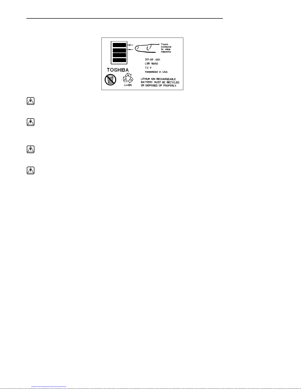
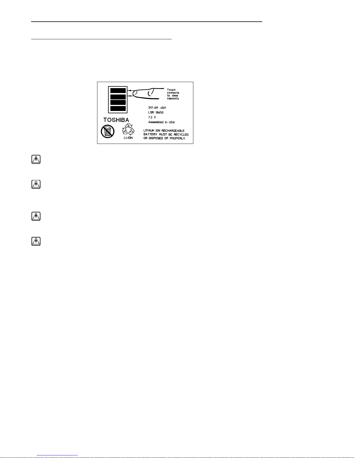
Rechargeable Battery Labelling 2-4. . . . . . .. . . . . . . .. . . . . . . .
Installing the Main Battery 2-5. . . . . . .. . . . . . . .. . . . . . . .. . . .
Removing the Main Battery 2-6. . . . . .. . . . . . . .. . . . . . . .. . . . .
Measuring Battery Pack Charge Level 2-8. . . . . . .. . . . . . . .. .
Charging Your Battery Pack 2-9. . . . . . .. . . . . . . .. . . . . . . .. . .
In Your Hand-Held Computer 2-9. . . . . . .. . . . . . . .. . . . . .
In An External Source 2-10.. . . . . . . .. . . . . . . .. . . . . . . .. . .
Battery Charger LED and Error Codes 2-12. . . . . . .. . . . . . . .. .
Charging Indicator Error Codes 2-12. .. . . . . . . .. . . . . . . .. . . . .
Backup Battery 2-13. . . . . . .. . . . . . . .. . . . . . . .. . . . . . . .. . . . . . .
Downloading Programs To Your Hand-Held Computer 2-14. . .
Programming the Flash 2-14. . . . . . .. . . . . . . .. . . . . . . .. . . . . . .
Turning Your Hand-Held Computer On and
Off (Suspending) 2-15. . . .. . . . . . . .. . . . . . . .. . . . . . . .. . . . .
Turning On Your Hand-Held Computer 2-15. . . . . . .. . . . . .
Suspending Your Hand-Held Computer 2-15.. . . . .. . . . . . .
Understanding the Key Clicks 2-16. . . . . . .. . . . . . . .. . . . . . . ..
ii PEN*KEYRModel 6400 Hand-Held Computer User’s Guide
Page 12

CONTENTS "
Scanning 2-17. . . . . . .. . . . . . . .. . . . . . . .. . . . . . . .. . . . . . . .. . . . .
Using an Integrated Scanner 2-17. . . . . . .. . . . . . . .. . . . . . .
Installing the Optional Scanning Handle 2-19. . . . . . .. . . .
Installing the Optional Scanning Handle with
Battery Pack 2-20. . . . . . .. . . . . . . .. . . . . . . .. . . . . . . ..
Charging the Scanner Handle Batteries 2-21. . . . . . .. . . . .
Using a Tethered Bar Code Scanner 2-22. . . . . . .. . . . . . . .. . . .
Tethered Scanner Supported 2-22. . . . .. . . . . . . .. . . . . . . ..
Software 2-24. . . . . . .. . . . . . . .. . . . . . . .. . . . . . . .. . . . . . . ..
Setting Terminal Emulation to Accept
Tethered Laser Scanners 2-24.. . . . . . .. . . . . . . .. . . . . .
Setting Your DOS Application to Accept
Tethered Laser Scanners 2-25.. . . . . . .. . . . . . . .. . . . . .
Setting Up Your LS3203 or LS3603 RS-232
Serial Scanner Parameters 2-25. . . . . . .. . . . . . . .. . . . .
SECTION 3
Terminal Emulation Menu Screens
Introduction 3-1. . . . . . .. . . . . . . .. . . . . . . .. . . . . . . .. . . . . . . .. .
Keyboard Functions 3-1. . . . . .. . . . . . . .. . . . . . . .. . . . . . . .. . . .
Yellow and Blue Shift Keys 3-1. . .. . . . . . . .. . . . . . . .. . . . .
Enter [ENT] Keys 3-2. . .. . . . . . . .. . . . . . . .. . . . . . . .. . . . .
Number Keys [0] Through [9] 3-2. . . . . . .. . . . . . . .. . . . . . .
Y Up and B Down Arrows 3-3. . . . . . . .. . . . . . . .. . . . . . . .
Display Annunciators 3-3. . . . . . . .. . . . . . . .. . . . . . . .. . . . . . . .
Display Position 0 3-3. . . . . . . .. . . . . . . .. . . . . . . .. . . . . . . .
Display Position 1 3-3. . . . . . . .. . . . . . . .. . . . . . . .. . . . . . . .
Display Position 2 3-4. . . . . . . .. . . . . . . .. . . . . . . .. . . . . . . .
Display Position 3 3-4. . . . . . . .. . . . . . . .. . . . . . . .. . . . . . . .
Display Position 4 3-4. . . . . . . .. . . . . . . .. . . . . . . .. . . . . . . .
Display Positions 5--8 3-5. . . . . . . .. . . . . . . .. . . . . . . .. . . . .
PEN*KEYRModel 6400 Hand-Held Computer User’s Guide iii
Page 13

CONTENTS "
Setting the Operating Parameters 3-6.. . . . . . .. . . . . . . .. . . . .
Opening the Main Menu 3-6.. . . . .. . . . . . . .. . . . . . . .. . . .
Opening the Set-Up Parms Menu 3-10. . . . . . .. . . . . . . .. . .
Protocol Options 3-24. . . . . .. . . . . . . .. . . . . . . .. . . . . . . .. . .
Display Options 3-34. . . . .. . . . . . . .. . . . . . . .. . . . . . . .. . . . .
Radio Comm 3-35. . . . . . .. . . . . . . .. . . . . . . .. . . . . . . .. . . . . .
Cold Start 3-36. . . .. . . . . . . .. . . . . . . .. . . . . . . .. . . . . . . .. . .
More 3-36. . . . . . .. . . . . . . .. . . . . . . .. . . . . . . .. . . . . . . .. . . . .
Print Device 3-37. . . . . . .. . . . . . . .. . . . . . . .. . . . . . . .. . . . . .
LCD Parms 3-37. . . . . . .. . . . . . . .. . . . . . . .. . . . . . . .. . . . . . . .. .
Screen Size 3-38. . . . . . .. . . . . . . .. . . . . . . .. . . . . . . .. . . . . . .
Screen Mode 3-39. .. . . . . . . .. . . . . . . .. . . . . . . .. . . . . . . .. . .
Annunciators 3-41. . . . . . . .. . . . . . . .. . . . . . . .. . . . . . . .. . . .
Key Uppercase 3-41. . . . . . .. . . . . . . .. . . . . . . .. . . . . . . .. . . .
Scroll Window 3-42. . . . . . .. . . . . . . .. . . . . . . .. . . . . . . .. . . .
Beeper Setup 3-42. . .. . . . . . . .. . . . . . . .. . . . . . . .. . . . . . . .. . . . .
Key Click 3-43. . . . . . .. . . . . . . .. . . . . . . .. . . . . . . .. . . . . . . ..
Error Tone 3-44.. . . . . . .. . . . . . . .. . . . . . . .. . . . . . . .. . . . . . .
Beeper Select 3-44. .. . . . . . . .. . . . . . . .. . . . . . . .. . . . . . . .. .
Tests 3-45. . . . . . .. . . . . . . .. . . . . . . .. . . . . . . .. . . . . . . .. . . . . . . .
Peripherals 3-45.. . . . . . .. . . . . . . .. . . . . . . .. . . . . . . .. . . . . .
Memory View 3-49. . . . . . .. . . . . . . .. . . . . . . .. . . . . . . .. . . . .
Packet Driver Test 3-49. . . . .. . . . . . . .. . . . . . . .. . . . . . . .. .
Histogram Opts 3-51. . . . . .. . . . . . . .. . . . . . . .. . . . . . . .. . . .
Numbers 3-52. . . . . . .. . . . . . . .. . . . . . . .. . . . . . . .. . . . . . . ..
Timed Numbers 3-52. . . . . . . .. . . . . . . .. . . . . . . .. . . . . . . .. .
Version Info (Information) 3-52. . . . . . . .. . . . . . . .. . . . . . . .. . . .
Exit Menus 3-53. . . . . . .. . . . . . . .. . . . . . . .. . . . . . . .. . . . . . . .. . .
More 3-53. . . . . . .. . . . . . . .. . . . . . . .. . . . . . . .. . . . . . . .. . . . . . . .
Keyboard Opts 3-53. . .. . . . . . . .. . . . . . . .. . . . . . . .. . . . . . . .
Save Parms 3-54. . . . . . .. . . . . . . .. . . . . . . .. . . . . . . .. . . . . . .
Session Menu 3-54. . . . . . .. . . . . . . .. . . . . . . .. . . . . . . .. . . . .
To Exit Emulation Mode and Return to DOS 3-56. . . . . . .. . . . .
iv PEN*KEYRModel 6400 Hand-Held Computer User’s Guide
Page 14

CONTENTS "
SECTION 4
Maintenance and Troubleshooting
Introduction 4-1. . . . . . .. . . . . . . .. . . . . . . .. . . . . . . .. . . . . . . .. .
Low Battery Indication 4-1. . . . . . .. . . . . . . .. . . . . . . .. . . . . . . .
Cleaning Your Hand-Held Computer 4-3. . . . . . .. . . . . . . .. . . .
Case and Display 4-3.. . . . . . . .. . . . . . . .. . . . . . . .. . . . . . . .
Docking Connectors 4-3. . . . . . . .. . . . . . . .. . . . . . . .. . . . . .
Troubleshooting 4-4. . . . . . .. . . . . . . .. . . . . . . .. . . . . . . .. . . . . .
Troubleshooting Table 4-4. .. . . . . . . .. . . . . . . .. . . . . . . .. . . . . .
Diagnostic Information 4-9. . . . . .. . . . . . . .. . . . . . . .. . . . .
Repair Service 4-10. . . . .. . . . . . . .. . . . . . . .. . . . . . . .. . . . . . . .. .
APPENDIX A
Connector Pin-Outs
8-Pin Docking Connector (standard) A-1. . . . . . .. . . . . . . .. . . .
Optional Communication Adapter 9-Pin D-Sub Connector A-2
APPENDIX B
NORANDRUtilities Program
Entry Point B-1. . . . . . .. . . . . . . .. . . . . . . .. . . . . . . .. . . . . . . .. .
Pop-Up Menus B-2. . . . . . .. . . . . . . .. . . . . . . .. . . . . . . .. . . . . . . .
Drop-Down Lists B-2. . . . . . .. . . . . . . .. . . . . . . .. . . . . . . .. . . . . .
Alphanumeric Fields B-3.. . . . .. . . . . . . .. . . . . . . .. . . . . . . .. . .
Title Screen B-4. . . . . .. . . . . . . .. . . . . . . .. . . . . . . .. . . . . . . .. . .
Language Selection B-5. . . . . .. . . . . . . .. . . . . . . .. . . . . . . .. . . .
PEN*KEYRModel 6400 Hand-Held Computer User’s Guide v
Page 15

CONTENTS "
Communications Menu B-6. . . . . . .. . . . . . . .. . . . . . . .. . . . . . . .
Option 1 BEGIN COMM SESSION B-7. . . . . . .. . . . . . . ..
Option 2 COMM SETTING B-15. . .. . . . . . . .. . . . . . . .. . . . .
Option 3 UNIT ID B-18. .. . . . . . . .. . . . . . . .. . . . . . . .. . . . . .
Option 4 NETWORK PARAMETERS B-18. . . . . . .. . . . . . . .
Option 4 MODEM PARAMETERS B-20. . .. . . . . . . .. . . . . .
Option 5 PHONE NUMBER B-24. . . . . . . .. . . . . . . .. . . . . . .
Option 9 ADVANCED UTILITIES B-25. . . . . . .. . . . . . . .. .
APPENDIX C
Keyboard Overlays
41-Key DOS/PC C-2.. . . . . . . .. . . . . . . .. . . . . . . .. . . . . . . .. . . . .
51-Key DOS/PC C-3.. . . . . . . .. . . . . . . .. . . . . . . .. . . . . . . .. . . . .
41-Key 5250 C-4. . . .. . . . . . . .. . . . . . . .. . . . . . . .. . . . . . . .. . . . .
51-Key 5250 C-5. . . .. . . . . . . .. . . . . . . .. . . . . . . .. . . . . . . .. . . . .
41-Key 3270 C-6. . . .. . . . . . . .. . . . . . . .. . . . . . . .. . . . . . . .. . . . .
51-Key 3270 C-7. . . .. . . . . . . .. . . . . . . .. . . . . . . .. . . . . . . .. . . . .
41-Key VT220 C-8. . . . . . .. . . . . . . .. . . . . . . .. . . . . . . .. . . . . . . .
51-Key VT220 C-9. . . . . . .. . . . . . . .. . . . . . . .. . . . . . . .. . . . . . . .
41-Key NATIVE C-10. . . .. . . . . . . .. . . . . . . .. . . . . . . .. . . . . . . ..
51-Key NATIVE C-11. . . .. . . . . . . .. . . . . . . .. . . . . . . .. . . . . . . ..
vi PEN*KEYRModel 6400 Hand-Held Computer User’s Guide
Page 16

CONTENTS "
FIGURES
Figure 1-1 Front View 1-4. . .. . . . . . . .. . . . . . . .. . . . . . . .. . . . .
Figure 1-2 Back View 1-5. . . .. . . . . . . .. . . . . . . .. . . . . . . .. . . .
Figure 1-3 Top View 1-6. .. . . . . . . .. . . . . . . .. . . . . . . .. . . . . . . .
Figure 1-4 Bottom View 1-6. . . . . .. . . . . . . .. . . . . . . .. . . . . . . .
Figure 1-5 41-Key Keyboard 1-8. . .. . . . . . . .. . . . . . . .. . . . . . .
Figure 1-6 51-Key Keyboard 1-9. . .. . . . . . . .. . . . . . . .. . . . . . .
Figure 1-7 Annunciator Locations On Display 1-15. . . . . . .. . .
Figure 1-8 Bottom End Handstrap Attachment 1-21. . . . . . .. .
Figure 1-9 Top End Handstrap Attachment 1-22. . . . . . . .. . . . .
Figure 1-10 Communication Adapter Scanner Connector 1-29
Figure 1-11 Communication Adapter Charger Connector 1-30.
Figure 1-12 Scanner Handle 1-31. . .. . . . . . . .. . . . . . . .. . . . . . .
Figure 1-13 Scanner Handle with Optional Battery Pack 1-32
Figure 1-14 Adjustable Handstrap 1-33.. . . . . . .. . . . . . . .. . . . .
Figure 1-15 Adjustable Wrist Strap 1-34.. . . . . . . .. . . . . . . .. . .
Figure 2-1 Resetting Your Computer 2-3.. . . . .. . . . . . . .. . . . .
Figure 2-2 Installing Main Battery Pack 2-5. . . . . . .. . . . . . . .
Figure 2-3 Removing Main Battery Pack 2-7.. . . . .. . . . . . . ..
Figure 2-4 Main Battery Pack Underside View
Showing Contacts 2-8. . . .. . . . . . . .. . . . . . . .. . . . . . . .. . . .
Figure 2-5 Multipack Charger 2-10. . . . . .. . . . . . . .. . . . . . . .. . .
Figure 2-6 Single Pack Charger 2-11. . . .. . . . . . . .. . . . . . . .. . .
Figure 2-7 Optional Scanner Handle 2-19. . . . . . .. . . . . . . .. . . .
Figure 2-8 Optional Scanner Handle with Battery Pack 2-20. .
Figure 2-9 Inserting Scanner Handle Into Charger 2-21. . . . . .
Figure 2-10 Connecting a Tethered Scanner 2-23. . . . . .. . . . . .
Figure A-1 8-Pin Docking Connector Pinouts A-1. .. . . . . . . ..
Figure A-2 9-Pin D-Sub Connector Pinouts A-2. . . . . . .. . . . . .
TABLES
Table 2-1 Charging Indicator Error Codes 2-12. . . . . . .. . . . . . .
Table 2-2 Solution Notes 2-13. . . . . . .. . . . . . . .. . . . . . . .. . . . . . .
Table 4-1 Basic Troubleshooting 4-4.. .. . . . . . . .. . . . . . . .. . . .
PEN*KEYRModel 6400 Hand-Held Computer User’s Guide vii
Page 17

CONTENTS "
viii PEN*KEYRModel 6400 Hand-Held Computer User’s Guide
Page 18

Section 1
General Information
" " " " " " " " " " " " " " " " " " " " " " " " " " " "
About this User’s Guide
This user’s guide is divided into four sections and three appendixes.
Summary of Sections
Section 1
Contains general information about the components of your
computer. This includes how the user’s guide is organized,
a summary of the sections, and the specifications for your
hand-held computer.
Section 2
Describes how to prepare for using your hand-held computer.
Section 3
Shows the terminal emulation menu screens for setting
parameters. This section only applies if you are running
NORANDRterminal emulation software.
PEN*KEYRModel 6400 Hand-Held Computer User’s Guide 1-1
Page 19

SECTION 1 " General Information
Section 4
Steps you through some procedures to use when troubleshooting your hand-held computer. This section also includes information for maintaining your computer. Routine
maintenance includes recharging the main battery pack;
replacing the handstrap; and cleaning the keyboard, connectors, and display.
Appendix A
Pin-outs for the external connectors.
Appendix B
NORAND ROM Utilities Programs are intended for your
system administrator for setting parameters to support
your application.
Appendix C
Contains terminal emulation overlays offered for your computer.
Unpacking and Inspecting
The following procedures explain what to do when your
hand-held computer arrives, and what to do if it has been
damaged in shipping:
1. Remove the hand-held computer from its shipping container and inspect for any visible damage.
2. If your hand-held computer was damaged in shipping,
record the model number, part number, and serial
number. These numbers can be found on the back side
of the hand-held computer.
3. Save all paperwork pertaining to shipment, and immediately notify the transport company of the damaged item(s). Follow their instructions for filing a
claim on the damaged items.
1-2 PEN*KEYRModel 6400 Hand-Held Computer User’s Guide
Page 20

SECTION 1 " General Information
Authorized repair of NORAND products is available only at
NORAND Service Centers. Unauthorized repair voids any
and all warranties. Contact your NORAND Sales Representative for additional instructions.
PEN*KEYRModel 6400 Hand-Held Computer User’s Guide 1-3
Page 21
SECTION 1 " General Information
Hand-Held Computer Main Components
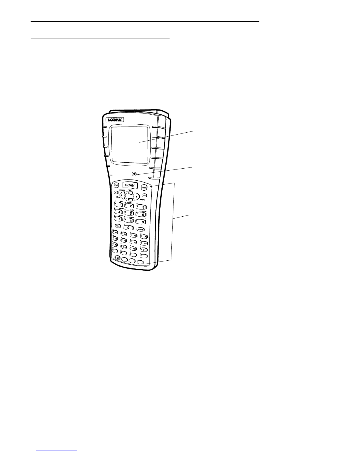
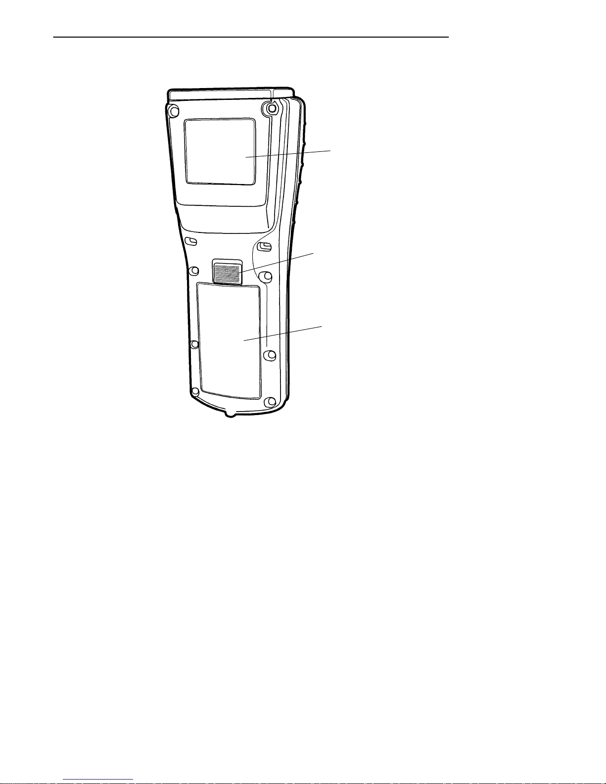
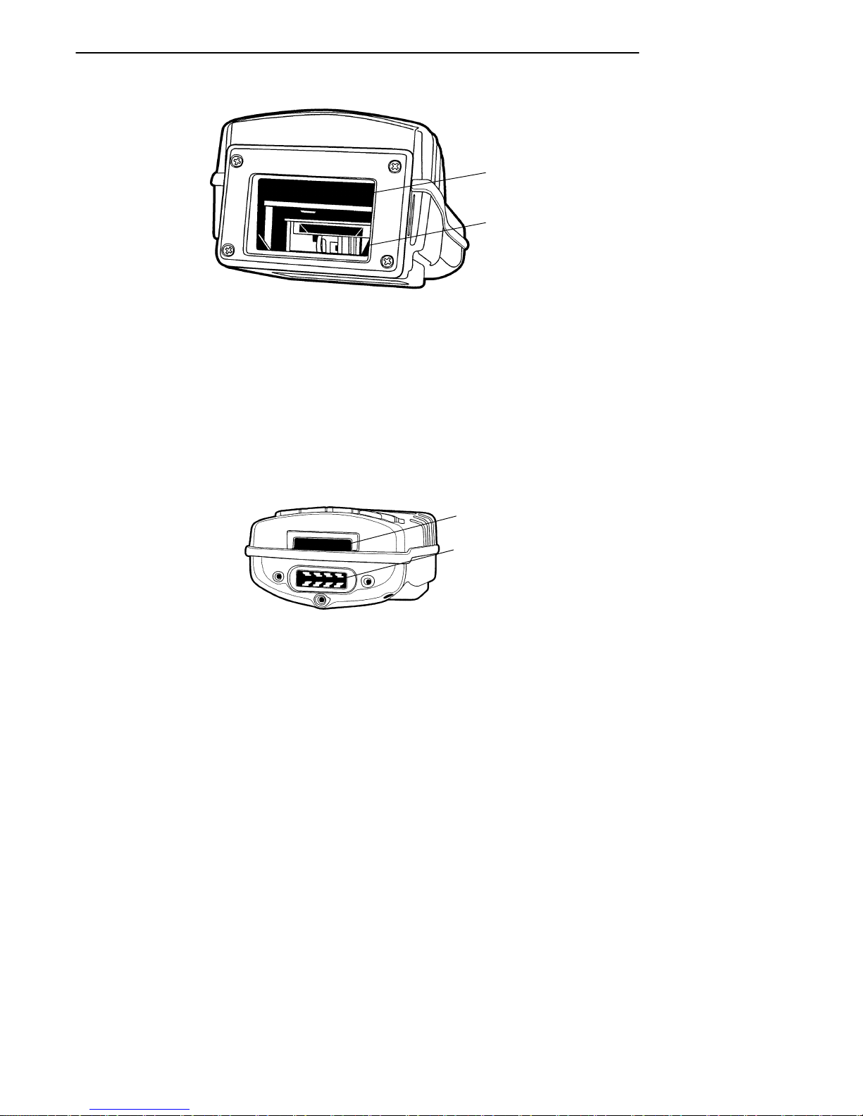
Figure 1-1, Figure 1-2, Figure 1-3, and Figure 1-4 on pages
1-4, 1-5, and 1-6 show you the location of the main components for your hand-held computer.
1
2
1. Display
2. Buzzer
3. Keyboard
Figure 1-1
Front View
1-4 PEN*KEYRModel 6400 Hand-Held Computer User’s Guide
3
Page 22
SECTION 1 " General Information
1
2
3
1. Label identifying model, serial number and class of scanner (optional)
2. Battery pack latch
3. Battery pack
Figure 1-2
Back View
PEN*KEYRModel 6400 Hand-Held Computer User’s Guide 1-5
Page 23
SECTION 1 " General Information
1
2
1. Radio card (optional)
2. Scanner (optional)
Figure 1-3
Top View
1. IrDA interface
2. Docking connector and optional communication adapter connector
Figure 1-4
Bottom View
1-6 PEN*KEYRModel 6400 Hand-Held Computer User’s Guide
1
2
Page 24

SECTION 1 " General Information
Hand-Held Computer Keyboard
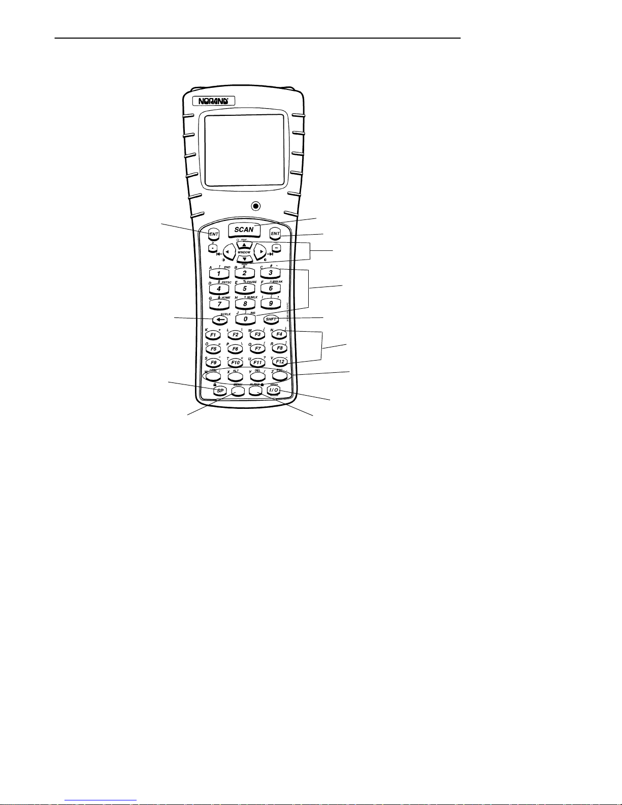
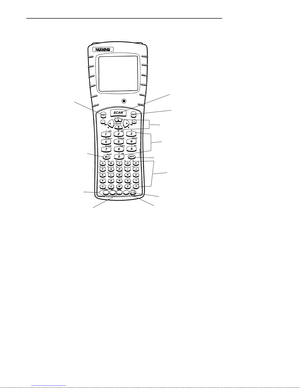
This hand-held computer provides two keyboard options.
Figure 1-5 on page 1-8 and Figure 1-6 on page 1-9 detail
the 41- and 51-key keyboards.
" For the 41-key keyboard, function and numeric keys
are single keystrokes. Alphabetical characters can be
entered by using the green, blue, or yellow shift keys.
" For the 51-key keyboard, alphabetic and numeric keys
are single keystrokes. Special function keys can be
entered by using the green, blue, or yellow shift keys.
Key Descriptions (41-Key)
1. Scan key
2. ENTER keys
3. Window scrolling keys
4. Numeric keys (0--9)
5. Green shift key
6. Function keys (F1--F12)
7. Special function keys
(depending on keyboard
overlay used)
8. l/O (Suspend/Resume) key
9. Yellow shift key
10. Blue shift key
11. Space key
12. Backspace key
Key Descriptions (51-Key)
1. Scan key
2. ENTER keys
3. Window scrolling keys
4. Numeric keys (0--9)
5. Green shift key
6. Alphabetic keys
7. l/O (Suspend/Resume) key
8. Yellow shift key
9. Blue shift key
10. Special function keys
(depending on keyboard
overlay used)
11. Backspace key
PEN*KEYRModel 6400 Hand-Held Computer User’s Guide 1-7
Page 25
SECTION 1 " General Information
11
2
12
10
1
2
3
4
5
6
7
8
9
1-8 PEN*KEYRModel 6400 Hand-Held Computer User’s Guide
Figure 1-5
41-Key Keyboard
Page 26
SECTION 1 " General Information
1
2
2
3
4
11
10
9
5
6
7
8
Figure 1-6
51-Key Keyboard
PEN*KEYRModel 6400 Hand-Held Computer User’s Guide 1-9
Page 27

SECTION 1 " General Information
Key Descriptions
This section includes a description of how the shift keys
work and the differences between a 41-key and 51-key keyboard. Your particular keyboard may have an overlay that
has additional keys other than those described in this section. Refer to your application operation manual for descriptions of those keys. The following descriptions cover
both the 41-key and 51-key computers using a DOS/PC
overlay.
ENT (Enter) Key
Two Enter keys are provided for the convenience of both left
and right handed users. These keys are the same as an ¿
(Enter) key on a PC. You use them to enter data, or as a
“Yes” response to display prompts.
SCAN Key
This key is used with an integrated scanner to read bar
code labels. If your application does not use a scanner or if
you are using an optional tethered scanner, you probably
will not use this key. Pressing this key also resumes operation (awaken your hand-held computer) if it is in the suspend mode.
Period [.] Key
Use the period [.] key as a period or a decimal point.
Minus [-] Key
Use the minus [--] key to enter negative values or dashes in
character fields. The minus key is also used for “No” responses to display prompts.
1-10 PEN*KEYRModel 6400 Hand-Held Computer User’s Guide
Page 28

SECTION 1 " General Information
Numeric Keys
Use the numeric keys as you would those on a calculator.
Numeric values are single keystroke operations.
Alphabetic Keys
Your computer provides the full alphabet on both the 41and 51-key keyboards. Alphabetic characters are single
keystroke operations with the 51-key keyboard but are two
keystrokes on a 41-key keyboard. Alphabetic characters
can be entered on the 41-key keyboard by using the blue
shift key.
Backspace [ ] Key
Use the backspace key to back the cursor up one character
at a time. Holding this key down causes the cursor to continuously move backwards until you stop or you run out of
space to move.
Shift Keys
Your hand-held computer has three different “shift” function keys. These keys temporarily shift the function of the
keyboard. Your keyboard has a green [SHFT] key, a blue
key and a yellow key. The green shift key is a standard
shift key. Both the blue and yellow keys work just like the
shift key, and allow access to different alternate functions.
Your keyboard may have up to three color-coded legends
(words or characters) above some of the keys. The green,
blue, or yellow “shift” keys correspond to those options.
PEN*KEYRModel 6400 Hand-Held Computer User’s Guide 1-11
Page 29

SECTION 1 " General Information
Green [SHFT] Key
Pressing the green [SHFT] key shifts the keyboard between
uppercase and lowercase for a single keystroke entry. If the
keyboard is set for uppercase character entry, pressing
green [SHFT] followed by a character key enters a single
lowercase character.
Blue Key
Use the blue shift key to enter single keystroke entries of
that shifted option. The blue shifted function relates to the
blue legends located above the keys.
Using a 41-Key Keyboard
On the 41-key keyboard, above the yellow shift key is Alphabetic Lock, illustrated by the symbol ALPHA . This
locks the keyboard so only the alphabetical characters are
entered. Press the blue key and then the yellow key.
The blue padlock is CAPS LOCK. This causes alphabetic
characters to be capitalized. Press the blue key and then
the space key.
ALPHABETIC or CAPS lock continues until the blue then
yellow shift keys are pressed again.
Using a 51-Key Keyboard
On the 51-key keyboard, there is no ALPHA Lock key because the alphabetical letters are not shifted functions.
Yellow Key
Use the yellow shift key to enter single keystroke entries of
that shifted option. The yellow shift functions relates to the
yellow legends on your keyboard.
1-12 PEN*KEYRModel 6400 Hand-Held Computer User’s Guide
Page 30

SECTION 1 " General Information
Using Shifted Functions
This section explains the use of the shift keys.
The Rules
The green [SHFT] key is the same as the SHIFT key on a
PC except that the green shift key also relates to those
characters where green legends appear above the keys.
EXAMPLE: On a PC, SHIFT [3] produces the # character, and that is the same
on the hand-held computer.
Contrast and backlighting are on the window scrolling arrow keys. The contrast control and backlight control are
not the same as the PC shift. This hand-held computer
uses shift left, shift right and shift up for contrast and backlight control. On a PC these key strokes produce a 4, 6, and
8. Numeric values 0--9 are available on all the 6400 HandHeld Computer versions, those keys are used for special
controls without causing compatibility issues.
Using the Shifted Functions
If the function you want is printed on the keyboard overlay
(in blue, yellow, or green) then you must first press that
colored shift key immediately before the desired color function. That two-key combination always defines that key.
EXAMPLE: A 41-key DOS/PC keyboard has the letter S in blue over the [F9]
key. Therefore, to produce a lowercase ’s’, press blue shift then the
[F9] key.
To produce an uppercase S, press the green [SHFT] key, then blue
shift, then the [F9] key.
‘S’ is always produced by pressing blue shift, then the [F9] key; if you
want to modify this, you press a modifier first.
EXAMPLE: To produce CTRL-S, press the [CTRL] key, then blue shift, then the
[F9] key for ‘S’.
To produce ALT-F9, press the [ALT] key, then the [F9] key.
PEN*KEYRModel 6400 Hand-Held Computer User’s Guide 1-13
Page 31

SECTION 1 " General Information
EXAMPLE: Pressing the green [SHFT] key and then the [DEL] key produces a
dot instead of deleting the character at the cursor. The nearby keys
on that row [CTRL], [ALT], and [ESC] still behave normally when the
green [SHFT] is pressed first.
This is why annunciators are absolutely crucial, since you
must only press one key at a time. The annunciators tell
you which shift key you are pressing and holding down. Refer to page 1-16 for locations and meanings of display annunciators.
Pressing more than one shift key along with another key
may not always produce the result you expected. This happens as a result:
" Of the sequence of keys pressed, and
" The mode your computer is in at the time the key is
pressed.
There is no problem when you press the green [SHFT] and
the yellow key. But if you press the [SHFT] and either the
blue or yellow shift key, you usually experience different
results than you expect.
Summary of Shift Key Combinations
" Green [SHFT] and either blue or yellow shift key and
another keystroke, no confusion
" Green [SHFT] and blue and yellow shift key along
with another key, confusion can occur
This is similar to your PC, if the NUM LOCK or CAPS
LOCK is engaged then pressing shift and a key usually produces something other than what you want. Therefore, just
like with a PC, to get the result you want you have to
change a mode or the sequence you press the keys.
1-14 PEN*KEYRModel 6400 Hand-Held Computer User’s Guide
Page 32
SECTION 1 " General Information
Display Annunciator Locations on
Display Window
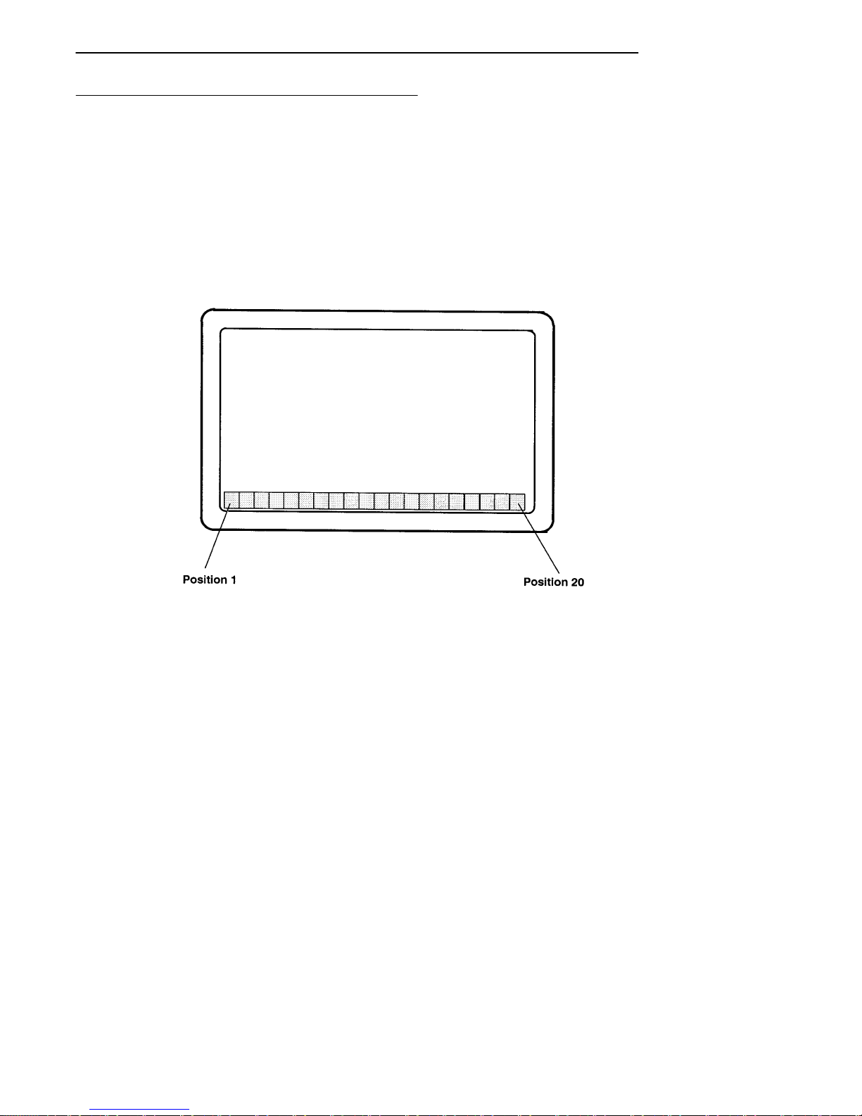
Annunciators are located at the extreme bottom of the display, in 20 separate positions. The following figure illustrates where each annunciator is positioned. Position 1 is
located in the lower left hand corner and position 20 completes the row in the lower right hand corner.
Figure 1-7
Annunciator Locations On Display
PEN*KEYRModel 6400 Hand-Held Computer User’s Guide 1-15
Page 33
SECTION 1 " General Information
Annunciator Descriptions
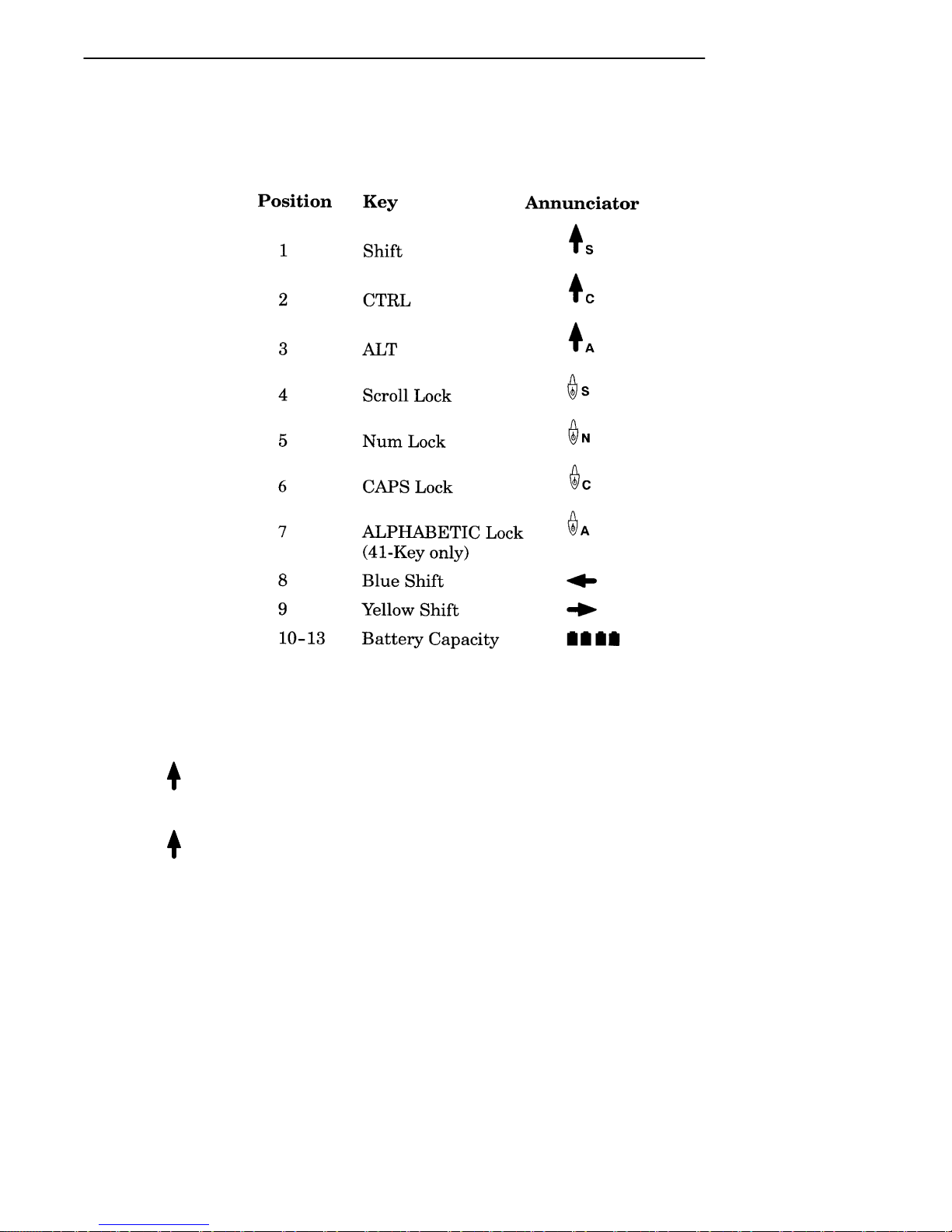
Annunciators appear on the bottom line of the display.
Display Annunciators (Messages)
The symbols contained in this section are larger than actual
size. The meaning of the annunciators is described below:
Shift mode: After holding down the green Shift [SHFT]
S
key, the next character will be uppercase or the alternative
function.
Control mode: Generally you use the Control mode as it
C
is designed in by your particular application.
1-16 PEN*KEYRModel 6400 Hand-Held Computer User’s Guide
Page 34

SECTION 1 " General Information
Alt mode: Generally you use the Alt mode as required by
A
your particular application.
Scroll lock mode: This mode locks the keyboard for
S
scrolling only. By using the scroll arrows on the
[WINDOW] keys you can continuously scroll through all
data entered. Your application and keyboard definition
show you which key is defined for scrolling. To unlock,
press the key again.
NUM lock mode: Both the 41-key and 51-key DOS/PC
N
keyboards have the option for locking the keyboard in numeric lock mode. Pressing the yellow shift then the number
8 key sets this function. To unlock, press the yellow shift
then the number 8 key again.
CAPS lock mode: The keyboard is in CAPS lock mode
C
when this annunciator is displayed on the bottom row of the
screen. All keystrokes are entered as uppercase characters.
To unlock CAPS press the [CAPS] key (51-key keyboard)
again or the blue shift and space key using the 41-key keyboard.
Alphabetic lock mode: Only the 41-key keyboards have
A
the option for locking the keyboard in alphabetic mode.
Only those keys that have alphabetic characters in the blue
shift mode are affected. The primary key function and the
alphabetic are swapped in Alphabetic Lock. Pressing the
blue shift and then the yellow shift toggles Alphabetic Lock
on and off. The following example shows how by using the
number 1 key you can produce characters 1 or A.
EXAMPLE: Normal Operation: Pressing the [1] key produces the character ‘1’;
pressing the blue shift key and then the [1] key produces an ‘A’.
Using the Alphabetic Lock: Pressing the [1] key produces an ‘A’;
pressing the blue shift key and then the [1] key produces the character ‘1’.
PEN*KEYRModel 6400 Hand-Held Computer User’s Guide 1-17
Page 35

SECTION 1 " General Information
Blue Shift Mode: This annunciator shows you that the
keyboard is in the blue shift mode. Pressing a key enters
the character or performs the function shown in blue on the
overlay to the upper left of the key.
Yellow Shift Mode: This annunciator displays when the
keyboard is in the yellow shift mode. Pressing a key enters
the character or performs the function shown on the overlay
in yellow to the upper right of the key.
Battery Pack Gas Gauge Icons:
These battery icons represent the charge level in your main
battery pack.
" Four icons indicates more than 76 % charge level
" Three icons indicates between 51--75%
" Two icons indicates between 26--50%
" One icon indicates between 21--25%
Once your computer gets below the 20% range, the icons are
replaced by “Ls” and after the charge level is less than 10%
your computer emits a series of beeps.
" Four Ls indicates between 16--20% charge level
" Three Ls indicates between 11--15%. At the 15%
charge level, your computer beeps once. The sound
duration and frequency are at levels you have set for
your computer.
" Two Ls indicates between 6--10%. At the 10% and 7%
charge levels, your computer beeps once. The sound
duration and frequency are at levels you have set for
your computer.
" One L indicates between 0--5%. At this charge level,
your computer beeps three times at its current setting
level for both duration and frequency.
"
NOTE: If you have the beeper turned off, you will not hear any of the low
battery beep warnings.
1-18 PEN*KEYRModel 6400 Hand-Held Computer User’s Guide
Page 36

SECTION 1 " General Information
The battery pack icons on your computer display reflect the
same status as the LEDs on the battery pack. However,
there may be a one minute delay for updating the icons on
the display when the battery pack is replaced.
Display Contrast
You can adjust the contrast of your display. Display contrast adjustment is a green [SHFT] function. To increase
the contrast, press the green [SHFT] key and then the [ ]
key (the window scroll-right arrow). To decrease the contrast, press the green [SHFT] key and then the [ ] key (the
left window scroll arrow).
Backlight
Your hand-held computer display has a backlight feature.
Backlighting the display helps when using your hand-held
computer in poorly lit working areas. To toggle the back light on and off press and hold the green [SHFT] key then
the backlight [ ] key (the window scroll-up arrow).
Window Scrolling Arrows
Use the window scrolling arrows while in the blue shift
mode to adjust the area of the screen that is visible. Pressing the blue shift key and then one of the arrow keys moves
the display one row or column at a time until the arrow key
is released. This allows you to pan across the entire virtual
CGA screen.
PEN*KEYRModel 6400 Hand-Held Computer User’s Guide 1-19
Page 37

SECTION 1 " General Information
[l/O] Suspend or Resume
Pressing the [I/O] key does not turn the hand-held computer off completely, but instead puts it into a suspend mode.
Suspend mode enables the hand-held computer to conserve
power but also enables it to respond quickly to data entry.
Your hand-held computer responds to the scan key, the trigger on the scanner handle, or the [I/O] key. To force your
computer into suspend, press the [I/O] key. Opening the
battery pack door latch also puts your computer into suspend.
The hand-held computer puts itself into suspend mode if no
activity has occurred for a set period of time. The time that
elapses before it suspends is determined by the parameters
you set using your application software, AUTOEXEC.BAT
or CONFIG.SYS files.
Handstrap
An elastic handstrap is included for your hand-held computer. Using the handstrap provides comfort to you and
also helps prevent you from accidentally dropping your
hand-held computer.
Whether you are left or right handed, the handstrap can be
secured to the hand-held computer to accommodate your
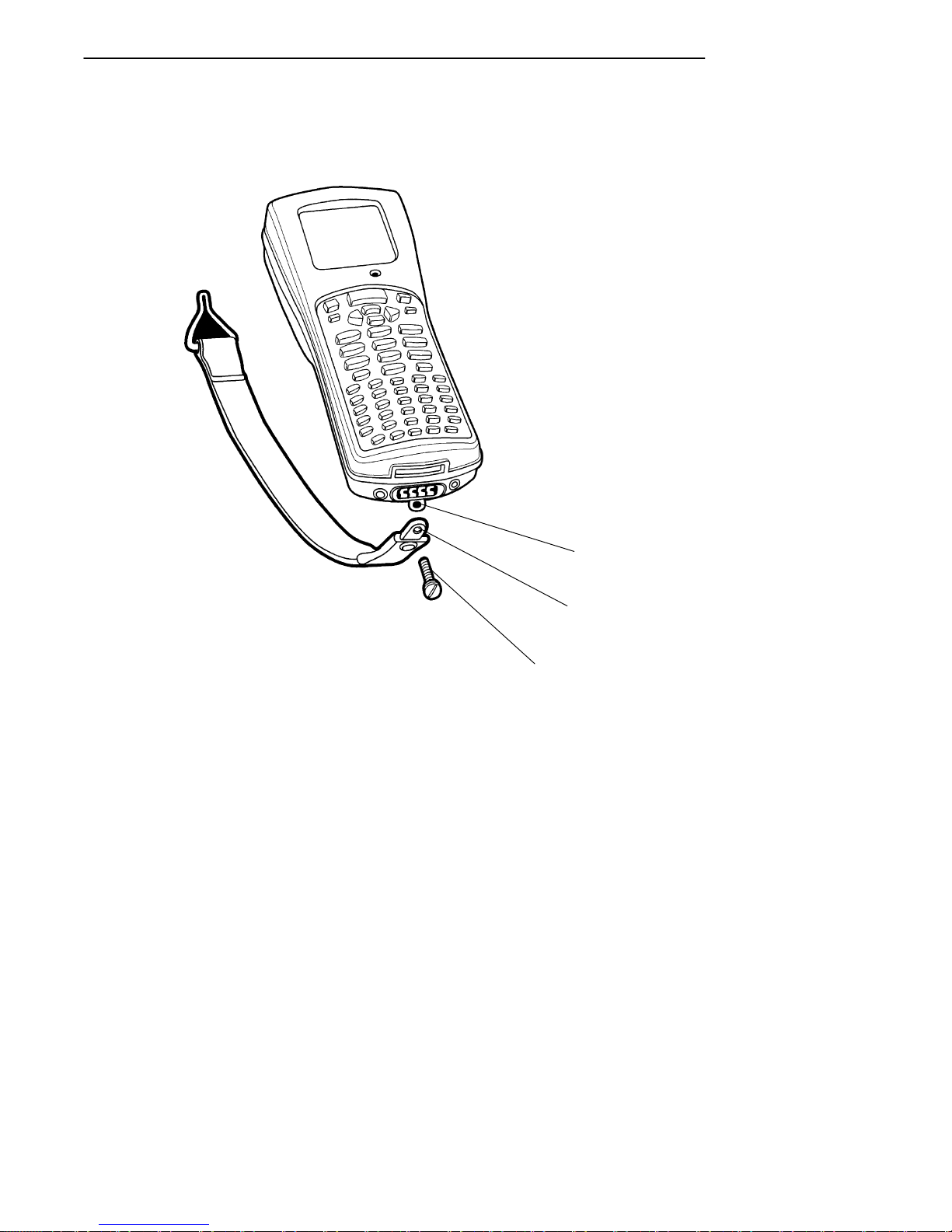
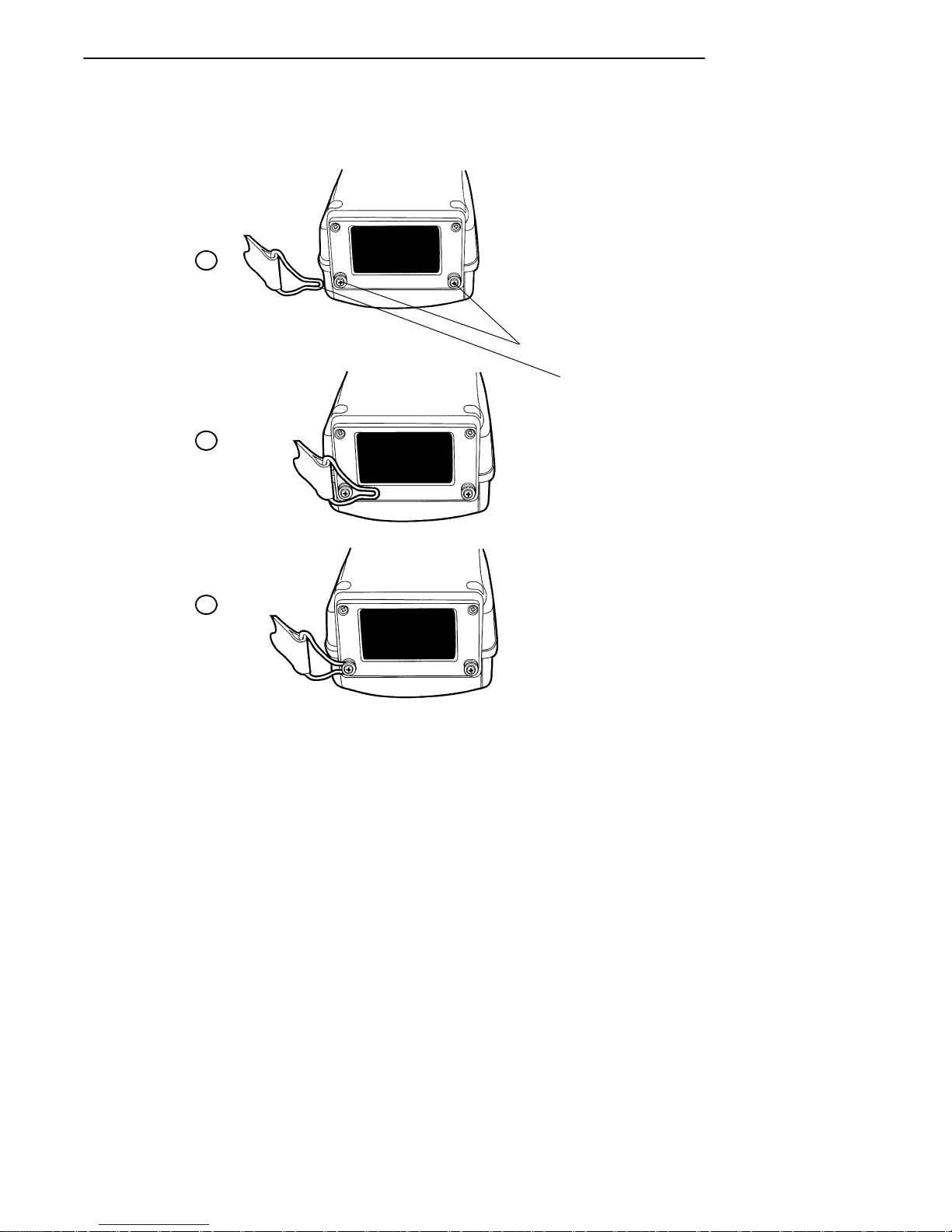
need. Figure 1-8 and Figure 1-9 show how to fasten the
handstrap to the top and bottom of your hand-held computer.
Available as options and accessories are an adjustable
handstrap and an adjustable wriststrap. These are shown
in Figure 1-14 and Figure 1-15 on pages 1-33 and 1-34 and
can be attached for either left or right handed use.
1-20 PEN*KEYRModel 6400 Hand-Held Computer User’s Guide
Page 38
SECTION 1 " General Information
1
2
3
1. Handstrap attachment screw hole
2. Handstrap screw attaching hole
3. Handstrap attaching screw
Figure 1-8
Bottom End Handstrap Attachment
PEN*KEYRModel 6400 Hand-Held Computer User’s Guide 1-21
Page 39
SECTION 1 " General Information
1
2
1
2
3
1. Handstrap attachment bushings
2. Handstrap clip fastener
Figure 1-9
Top End Handstrap Attachment
1-22 PEN*KEYRModel 6400 Hand-Held Computer User’s Guide
Page 40

SECTION 1 " General Information
Buzzer
The buzzer sounds when you press a key (the “key click”) or
make a good scan, or when certain error conditions occur.
Refer to Figure 1-1 on page 1-4 for the location of the buzzer.
B
CAUTION: Keep all foreign material out of the buzzer opening. The buzzer
opening is not a pencil or pen holder. The buzzer is sealed but
could be punctured by sharp objects which harm the buzzer
and allow rain, dirt, or other materials to get inside your
hand-held computer.
You can adjust the frequency and length of time of the buzzer tones through your parameter settings. The parameter
settings are detailed in Section 3.
Infrared (IrDA) Port
The IrDA port provides for the transmitting of an infrared
signal to:
" A printer equipped with an IrDA adapter
" A personal computer with IrDA serial adapter
" Any other IrDA compatible device
Battery Management
The normal charge time for the main battery pack is 1.5
hours for a 2 cell pack and 3 hours for a 4 cell pack.
You should charge the battery pack until the green LED on
the charger comes on, indicating a fully charged pack.
PEN*KEYRModel 6400 Hand-Held Computer User’s Guide 1-23
Page 41

SECTION 1 " General Information
A fully charged battery pack, left outside of a charger or
your computer, self discharges in about 20 days. It is best
to take batteries directly from the charging device and
install them into your computer.
Your battery packs are rated for 500 full charge/discharge
cycles after which they have 50% of their original capacity.
The main and backup batteries will not charge below 32_F
(0_C) and above 104_F(40_C). The battery life of the cells
is reduced when running in cold temperatures.
EXAMPLE: Your computer should be used only two shifts a day in a below 0_C
environment to allow eight hours for the internal backup battery to
recharge in room temperature.
It is always a good idea to check the capacity of your battery
pack before inserting it into your computer, and charge accordingly. Refer to Measuring Battery Pack Charge
Level on page 2-8 for instructions.
Battery
Main Battery Pack
The hand-held computer offers rechargeable lithium ion
main battery packs in:
" Two cell
" Four cell
" Four cell in optional scanner handle
1-24 PEN*KEYRModel 6400 Hand-Held Computer User’s Guide
Page 42
SECTION 1 " General Information
9
WARNING: The battery can explode if it is incorrectly replaced. Replace
only with the same or equivalent kind.
AVERTISSEMENT: La batterie au lithium peut exploser si elle est replacée de
manière incorrecte. Elle ne doit être remplacée que par une
batterie identique ou similaire.
WARNING: The lithium battery can explode if placed incorrectly in the
charger.
AVERTISSEMENT: Les batteries au lithium peuvent exploser ou prendre feu si
elles sont trop chargées à cause d’une mauvaise installation
de la station d’accueil.
When your hand-held computer goes into suspend mode because of low main battery condition, the data is protected by
the backup battery. Your hand-held computer will not accept data or process transactions until you deal with the
low battery condition. The backup battery protects the data
that you have entered for at least 100 hours.
PEN*KEYRModel 6400 Hand-Held Computer User’s Guide 1-25
Page 43

SECTION 1 " General Information
Backup Battery
Your hand-held computer contains a rechargeable nickelmetal hydride backup battery. This backup battery recharges when needed from either an external charging
source (like a printer or dock) or from the main battery
pack. If the backup battery is completely run down it takes
a minimum of 8 hours to completely recharge but it is better to recharge it for a full 12 hours.
The backup battery remains ready to protect your
computers data whenever the main battery pack is removed
or needs recharging. The backup battery should last about
500 cycles (discharge and recharge equals a cycle). This
battery should last for about 5 years before it needs to be
replaced. If your hand-held computer fails to hold data for
at least 100 hours in the suspend mode, send your
computers to the Norand Customer Support Center for
replacement.
Memory
This hand-held computer design uses these types of
memory:
" Main Memory DRAM
" Flash
Main Memory
Your main memory DRAM options available are 2, 4 or 8
Megabytes. The hand-held computer main memory was ordered at the time your unit was purchased. To add additional memory, send your hand-held computer into your Norand Customer Support Center.
The main memory is protected by the backup battery during low or dead main battery conditions or when the main
battery pack is removed.
1-26 PEN*KEYRModel 6400 Hand-Held Computer User’s Guide
Page 44

Flash
Flash memory is available in 2 or 4 Megabytes. Flash
stores the BIOS and DOS. Software stored in flash is copied into DRAM for execution. Your application may also
store information in flash memory. Flash memory retains
data even if all power sources are depleted.
Diagnostic EEPROM
The hand-held computer collects and stores diagnostics.
They can provide useful information to a Norand Customer
Support Specialist, should your hand-held computer fail to
operate. You will be instructed by the Norand personnel to
complete the necessary steps while they are troubleshooting
your computer with you.
SECTION 1 " General Information
Resetting
In the rare event that your hand-held computer fails to respond to your input, it may be necessary to “reset.” A
“hard” reset of your hand-held computer is done by holding
down the Blue, Yellow and both ENT (Enter) keys all at the
same time, until your computer starts beeping. This usually takes about 1--2 seconds. This method is equivalent to
powering off and on with a PC. Resetting (also called rebooting) can take your hand-held computer up to 45 seconds.
Depending on the type of overlay your hand-held computer
is programmed for, usually a “soft” reset is done by pressing
Ctrl, Alt, and Delete.
PEN*KEYRModel 6400 Hand-Held Computer User’s Guide 1-27
Page 45

SECTION 1 " General Information
Batch Terminal Operation
Your hand-held computer contains internal memory so it
can collect and store data and then at the end of a day or
shift, transmit (send) it to a centrally located host computer.
Many applications do this upload and download of information daily, but sometimes this may happen several times a
day, or only occur weekly.
Terminal Emulation
In Terminal Emulation you are using your hand-held
computer to imitate the appearance and operation of
another terminal (usually a particular IBM or DEC display
monitor). The keyboard overlays for the emulated
terminals supported by this hand-held computer are
contained in Appendix B.
Accessories and Options
Internal Scanner
Your hand-held computer can be ordered with an internal
integrated scanner. An integrated scanner provides the
convenience of having a hand-held computer and scanner in
one, for the freedom of one handed operation.
Internal Radio
Your hand-held computer can be factory equipped with either a 902 MHz or 2.4 GHz spread spectrum radio. This
hand-held computer with a radio provides for both batch
(store and forward data transfer later) and real-time (right
now) interaction with your host computer or network for
flexibility of operation.
1-28 PEN*KEYRModel 6400 Hand-Held Computer User’s Guide
Page 46
SECTION 1 " General Information
Communication Adapter
B
CAUTION: The pins on the external connectors of the hand-held computer
are fragile. Attach or disconnect cables with care to prevent
damaging the connectors.
External Scanner Connector
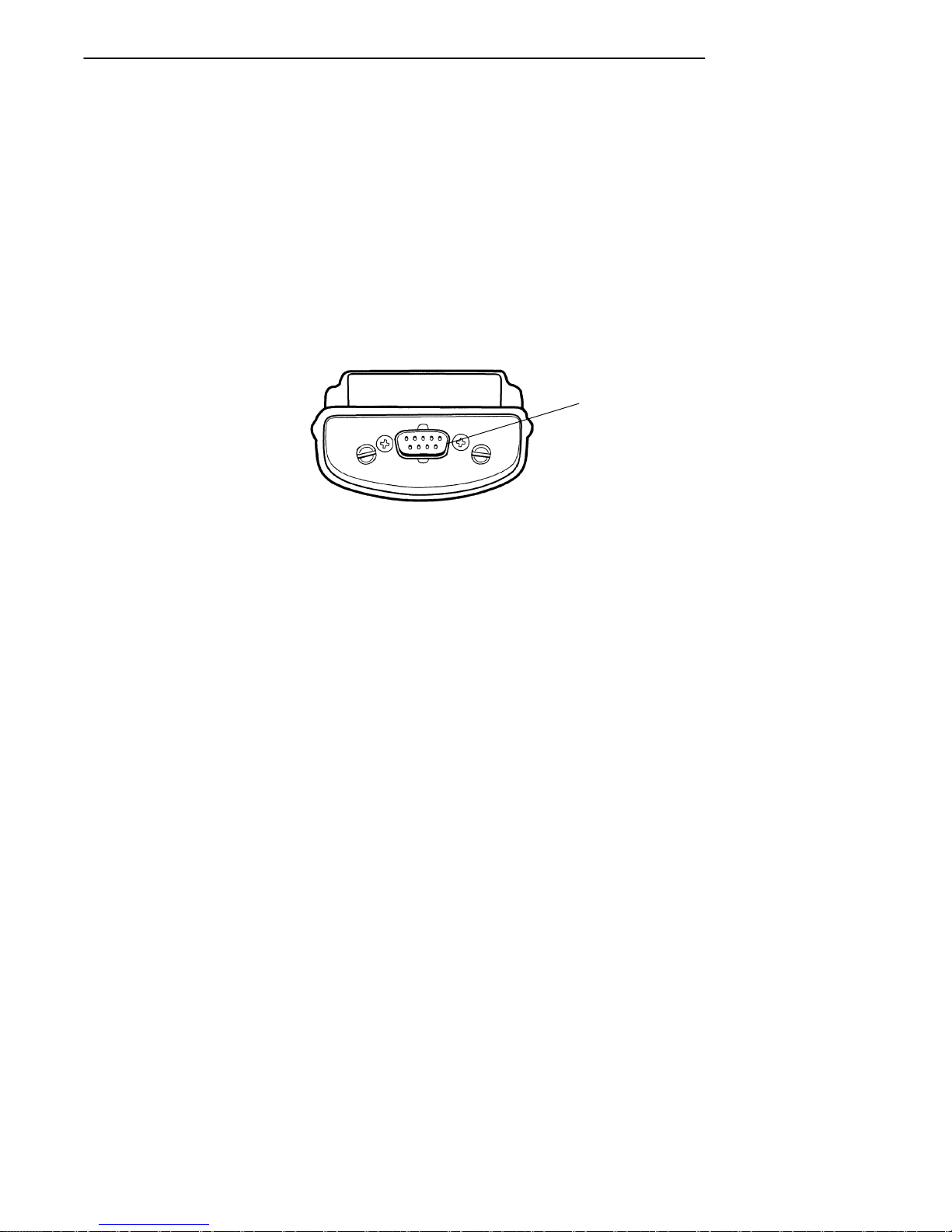
The Communication Adapter contains a 9-pin connector for
attaching a tethered scanner. Appendix A on page A-2 contains the pinouts for this connector.
1
1. Scanner connector
Figure 1-10
Communication Adapter Scanner Connector
PEN*KEYRModel 6400 Hand-Held Computer User’s Guide 1-29
Page 47
SECTION 1 " General Information
Charge Jack
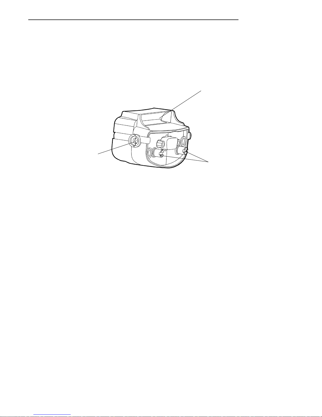
The Communication Adapter contains a charge jack on the
side for connecting and charging your hand-held computer
using an optional AC wall charger or DC cigarette charger
accessory.
3
1
2
1. Infrared transceiver lens
2. Communication adapter attachment screws
3. External charge jack
Figure 1-11
Communication Adapter Charger Connector
1-30 PEN*KEYRModel 6400 Hand-Held Computer User’s Guide
Page 48
SECTION 1 " General Information
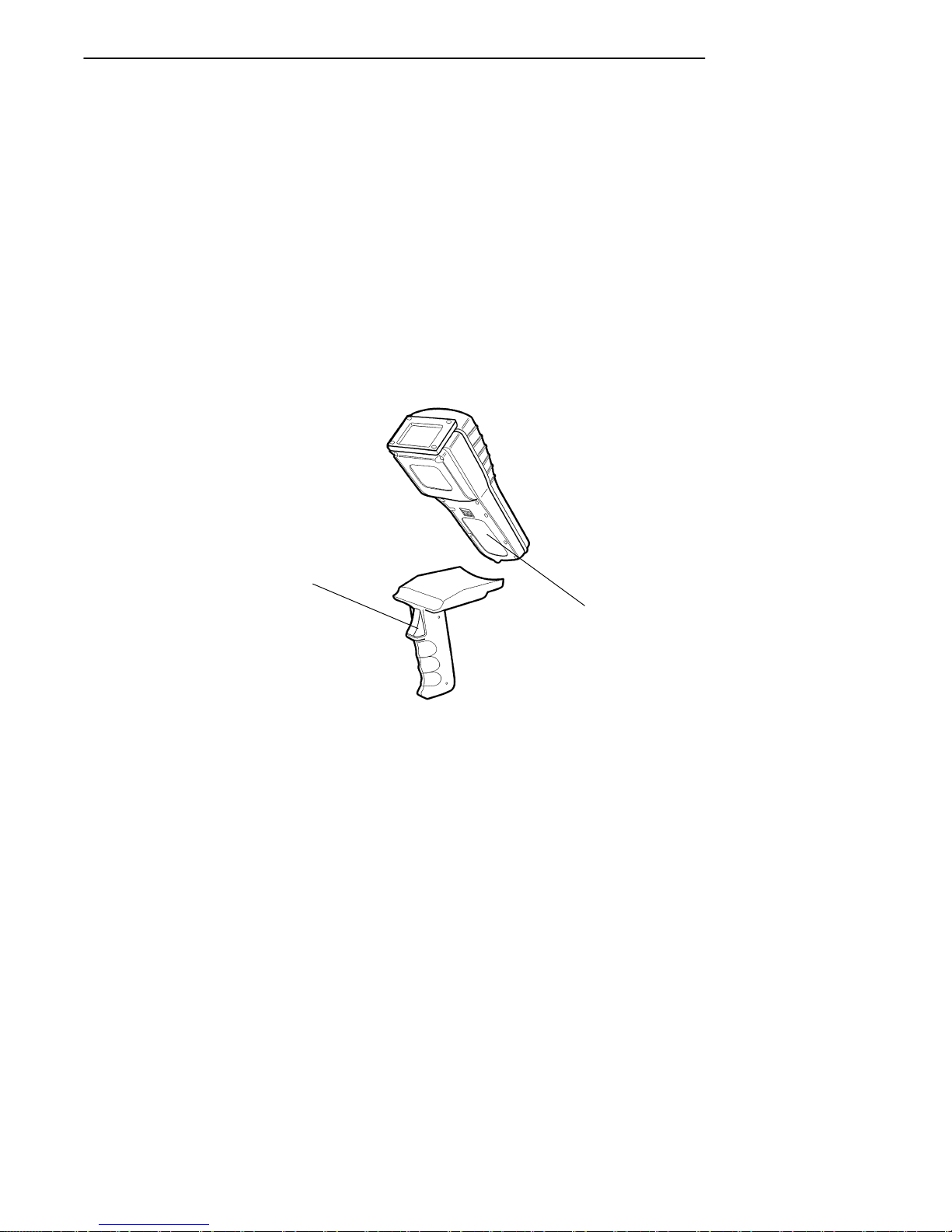
Scanner Handle
If you do a lot of scanning, using the optional scanning handle gives you a means for point and shoot scanning. The
scanning handle offers these advantages:
" Lightweight
" Easy to connect and use
" Optional four cell battery pack
" Can easily detach so the batteries can be charged sep-
arately from the hand-held computer
2
1
1. Two cell battery pack in hand-held computer
2. Scanning trigger
Figure 1-12
Scanner Handle
PEN*KEYRModel 6400 Hand-Held Computer User’s Guide 1-31
Page 49
SECTION 1 " General Information
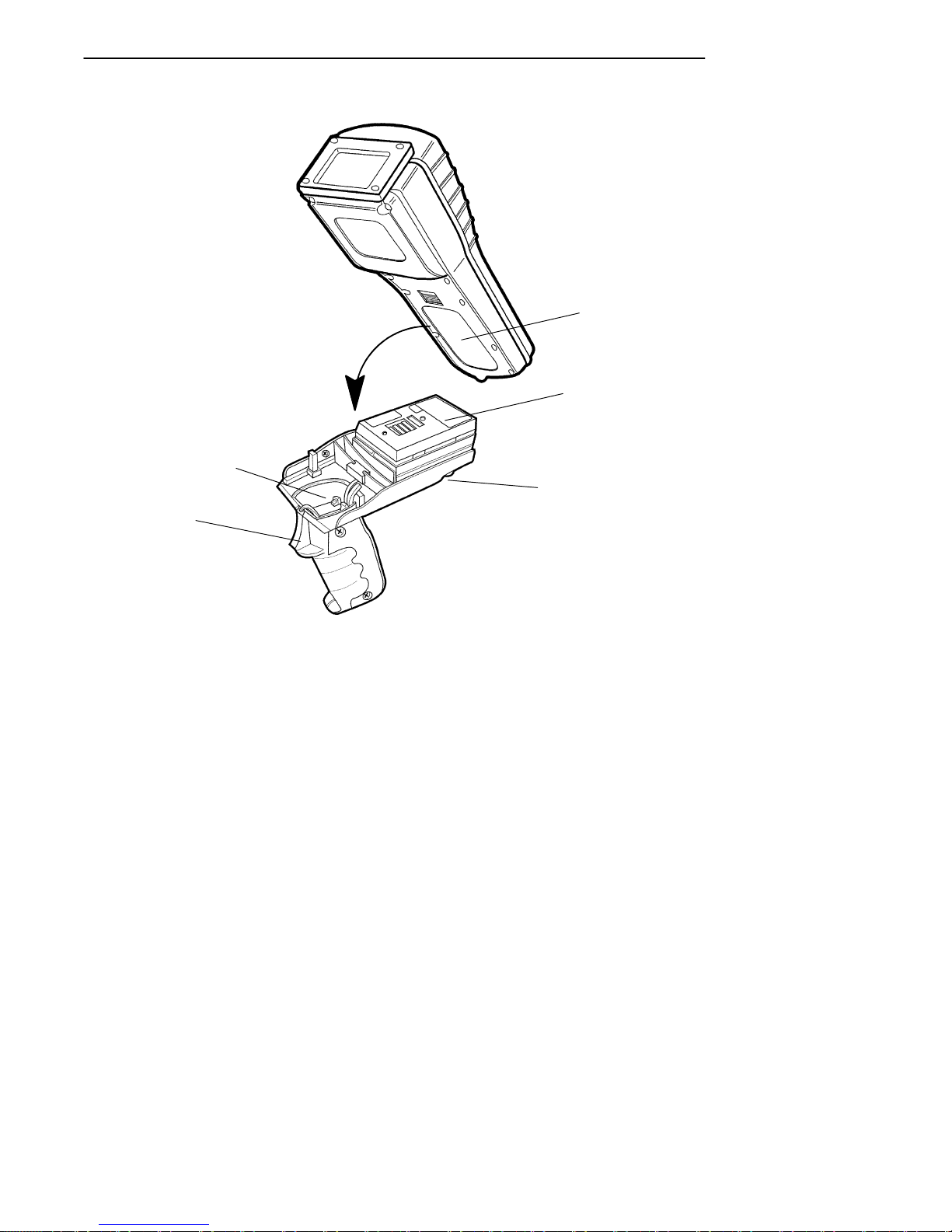
5
1
2
3
4
1. Battery compartment
2. Battery pack to fit in computer battery compartment
3. Button to release handle from computer
4. Scanning trigger
5. Battery pack in handle
Figure 1-13
Scanner Handle with Optional Battery Pack
1-32 PEN*KEYRModel 6400 Hand-Held Computer User’s Guide
Page 50
SECTION 1 " General Information
Adjustable Wrist Strap and
Adjustable Handstrap
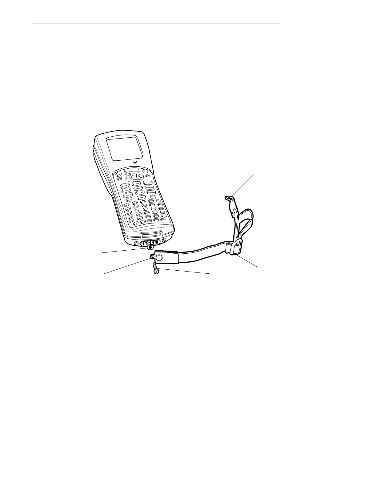
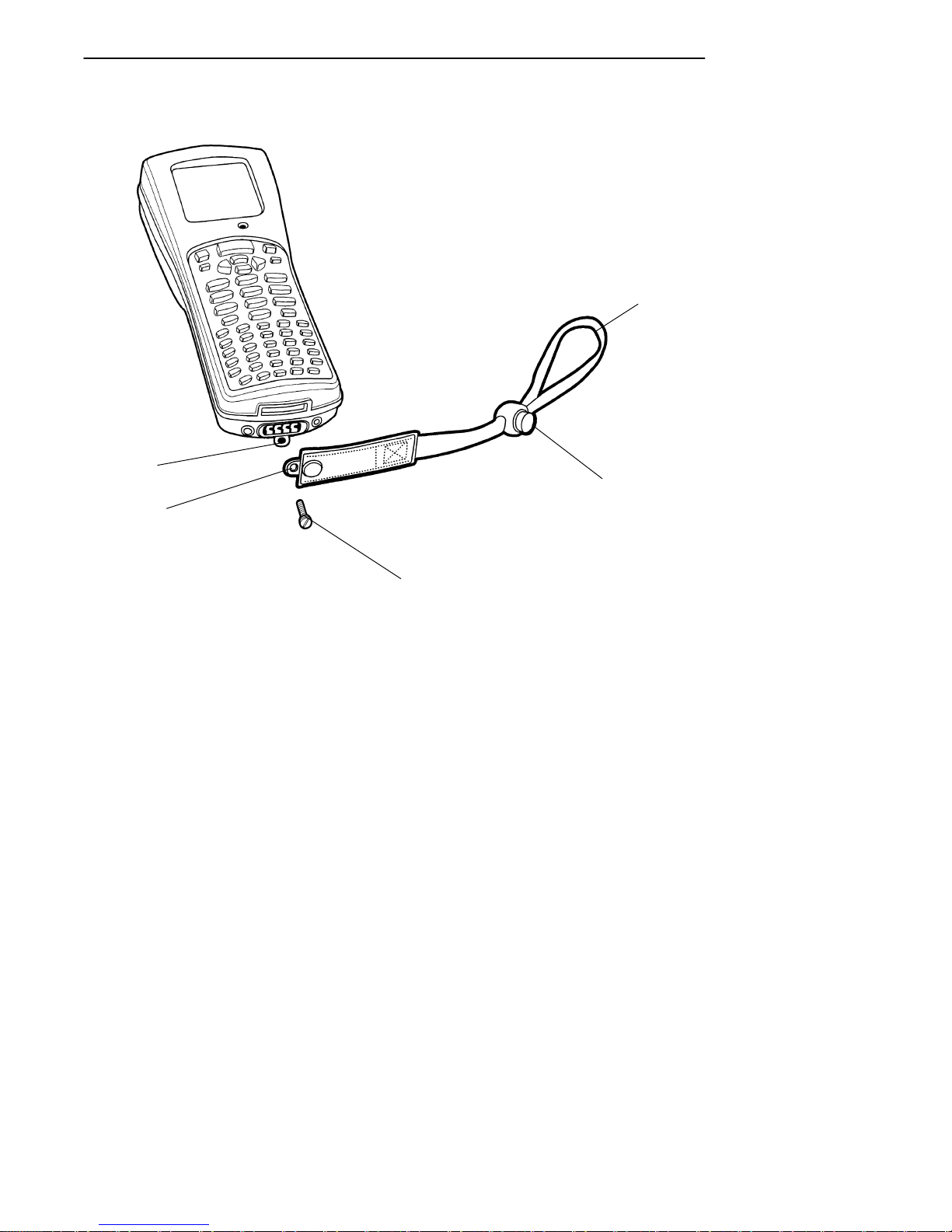
You can order an optional adjustable wrist strap or
handstrap. Figure 1-14 and Figure 1-15 show how to attach
and adjust these optional straps.
1
5
4
1. Top handstrap clip fastener
2. Handstrap adjustment buckle
3. Bottom handstrap attachment screw
4. Handstrap attachment screw hole
5. Computer handstrap attachment screw hole
3
Figure 1-14
Adjustable Handstrap
PEN*KEYRModel 6400 Hand-Held Computer User’s Guide 1-33
2
Page 51
SECTION 1 " General Information
5
1
2
4
3
1. Wrist loop
2. Adjustment knob (push button in, slide knob down strap)
3. Wrist strap attachment screw
4. Wrist strap attachment screw hole
5. Computer wrist strap attachment screw hole
Figure 1-15
Adjustable Wrist Strap
1-34 PEN*KEYRModel 6400 Hand-Held Computer User’s Guide
Page 52

SECTION 1 " General Information
4cellLithiumIonbatterypack(optional
)
Hand-Held Computer Specifications
Size: 8.8 inches (22.35 cm) long
3.3 inches (8.4 cm) wide at display; 2.9 inches
(7.4 cm) at keyboard
2.2 inches (5.6 cm) tall
Temperature:
Recommended
Operating:
Storage:
Weight: 17--20 ounces (¶ 481--567 g) depending on options
Humidity: 0 to 100% noncondensing
Static
Protection: 20 kV
Power source:
Main battery: 2 cell Lithium Ion battery pack (standard)
Backup
battery:
Charging rate:
0 to +40 _C:
(32 to 104 °F)
Communication:
Physical
devices:
Protocol: RS-232 protocols like xmodem, ymodem, zmodem,
--4 to +122_F (--20 to +50_C)
--22 to +158_F (--30 to +70_C)
added
4 cell Lithium Ion battery pack (optional)
4 cell Lithium Ion pack in scanner handle (option-
al)
150 mA nickel-metal hydride (NiMH) battery
(standard)
Fast charge (fully charge ¶ 1.5 hours for a 2 cell
pack and 3 hours for a 4 cell pack)
Asynchronous RS-232 and RS-485, IrDA, Wireless
Local Area Network
and Kermit; Norand Printer Communications
Protocol (NPCP); IrDA through an IR adapter.
For RF applications: TCP/IP, Novell, any Ethernet
network protocol that can operate with the ODI
specification
PEN*KEYRModel 6400 Hand-Held Computer User’s Guide 1-35
Page 53

SECTION 1 " General Information
System Components:
FLASH: 1, 2, or 4 megabytes (MB)
DRAM: 2, 4 or 8 megabytes (MB)
Processor: AM386SC300, mixed 3.3 and 5 volt, 33 MHz.
Display:
Type: CGA compatible LCD
Size: 160 (wide) by 128 (long) pixels;
Radio Module:
2.4 GHz Spread Spectrum
Interface: Internal
Range: Up to 500 feet (152 meters)
Data Rates
(throughput):
Modulation: Frequency Hopping Spread Spectrum (FHSS)
Frequency
Band:
Output Power 100 mW
Radio Module:
902 mHz Spread Spectrum
Interface: Internal
Range: Up to 1200 feet (366 meters) line of sight
Data Rates
(throughput):
Modulation: Direct Sequence Spread Spectrum (DSSS)
Frequency
Band:
Output Power 250 mW
800 kbps or 1.6 Mbps, auto selecting
2400-2483 GHz
90,225,450 kbps, programmable
902--928 MHz
1-36 PEN*KEYRModel 6400 Hand-Held Computer User’s Guide
Page 54

900 MHz Radio Option
NIC* Device Model Name
Type III 6710 Access Point . . . . . . .
PEN*KEYR6400 . . . . . ..
PEN*KEY 6600 . . .. . . . .
PEN*KEY 6100 . . . . . . ..
Radio
modules
*Consult a Norand representative for availability.
NIC Specifications
RT1100 . . . . . . .. . . . . . . ..
RT1700 . . . . . . .. . . . . . . ..
SECTION 1 " General Information
RM160
RM160
RM160
RM160
RM60, RM70, RM70LR
(radio modules)
RM60, RM70, RM70LR
(radio modules)
Following are networking specifications for the 900 MHz
NIC.
Frequency band: 902--928 MHz spread spectrum direct sequence
Range: Up to 1300 feet line of sight
Coverage: 100,000--350,000 square feet in typical indoor
installations
Data rate: 90, 225, or 450 Kbps (depends on installation)
Channelization: 7 @ 90 Kbps, 1 @ 225 or 450 Kbps
Client driver: ODI
Software compatibility Requires NORAND communications software resident in
the access point
Output power: 250 mW
MAC protocol: NORAND open wireless LAN MAC radio protocol
Regulatory
compliance:
FCC 15.247; Industry Canada RSS 210 (Consult a
Norand representative for availability.)
PEN*KEYRModel 6400 Hand-Held Computer User’s Guide 1-37
Page 55

SECTION 1 " General Information
2.4 GHz Radio Option
Access Point NIC* Device Model Name
Type III 6710 Access Point RM180
*Requires NORAND communications software resident in the access
point.
Wireless
Station
NIC* Device Model Name
Type III PEN*KEY 6400 . .. . . . .
PEN*KEY 6600 . . .. . . .
Type II Laptops and notebooks . RM185
Mini-ISA PEN*KEY 6100 . . .. . . .
RT1100 . . . . . . .. . . . . . . .
RT1700 . . . . . . .. . . . . . . .
ISA Desktops . . . .. . . . . . . .. . RM380
*Consult a Norand representative for availability.
RM180
RM180
RM280
RM80, RM90, RM90LR
(radio modules)
RM80, RM90, RM90LR
(radio modules)
1-38 PEN*KEYRModel 6400 Hand-Held Computer User’s Guide
Page 56

SECTION 1 " General Information
NIC Specifications
Following are networking specifications for the Proxim 2.4
GHz NIC.
Frequency band: 2.401--2.480 GHz SST frequency hopping
Range: Up to 500 feet line of sight
Coverage: 25,000 ft2(2,322 m2) typical indoors
Data rate: 800 Kbps or 1.6 M bps, manual or autoselect
Client drivers: ODI and NDIS (v. 2.0.1/DOS and Windows)
6710 & 6910
(access point/gateway)
Ethernet compatibility: Ethernet packet types and addressing
Output power: 100 mW
MAC protocol: RangeLAN2
Regulatory compliance: FCC 15.247; Industry Canada RSS 210; European Union
Requires NORAND communications software in the
access point or access point/gateway
ETS 300-328 (Consult a Norand representative for avail-
ability.)
Radio and Scanner Modules
Module Description
RM11 UHF radio
RM31 UHF radio with integrated, standard-range scanner or long-range scan-
ner
RM60 900 MHz radio
RM70 900 MHz radio with integrated, standard-range scanner
RM70LR 900 MHz radio with integrated, long-range scanner (such as used on a
forklift)
RM80 2.4 GHz radio
RM90 2.4 GHz radio with integrated, standard-range scanner
RM90LR 2.4 GHz radio with integrated, long-range scanner (such as used on a
forklift)
PEN*KEYRModel 6400 Hand-Held Computer User’s Guide 1-39
Page 57

SECTION 1 " General Information
1-40 PEN*KEYRModel 6400 Hand-Held Computer User’s Guide
Page 58

Section 2
Operation
" " " " " " " " " " " " " " " " " " " " " " " " " " " "
Introduction
This section tells you how to:
" Install and remove the main battery pack
" Charge the battery pack
" Download applications and parameters
" Program the Flash memory
" “Power-up” your hand-held computer
" Understand the key clicks
" Scan using integrated (internal) or tethered (external)
scanners
Before Using Your Computer for the First
Time
Your computer is shipped with uncharged batteries for safety reasons. Charge your computer for 12 hours before using
it the first time. This ensures that both the main and backup batteries are fully charged. For complete charging
instructions refer to Charging Your Battery Pack begin-
ning on page 2-9.
"
NOTE: After the initial charging of 12 hours, the normal charge time for the
main battery pack is 1.5 hours for a 2 cell pack and 3 hours for a optional scanner handle with 4 cell pack.
PEN*KEYRModel 6400 Hand-Held Computer User’s Guide 2-1
Page 59

SECTION 2 " Operation
If you use batteries and external battery pack chargers but
do not use docks to charge the batteries, you need to fully
charge your backup battery. To ensure the backup battery
is fully charged:
1. Insert a fully charged main battery into your computer.
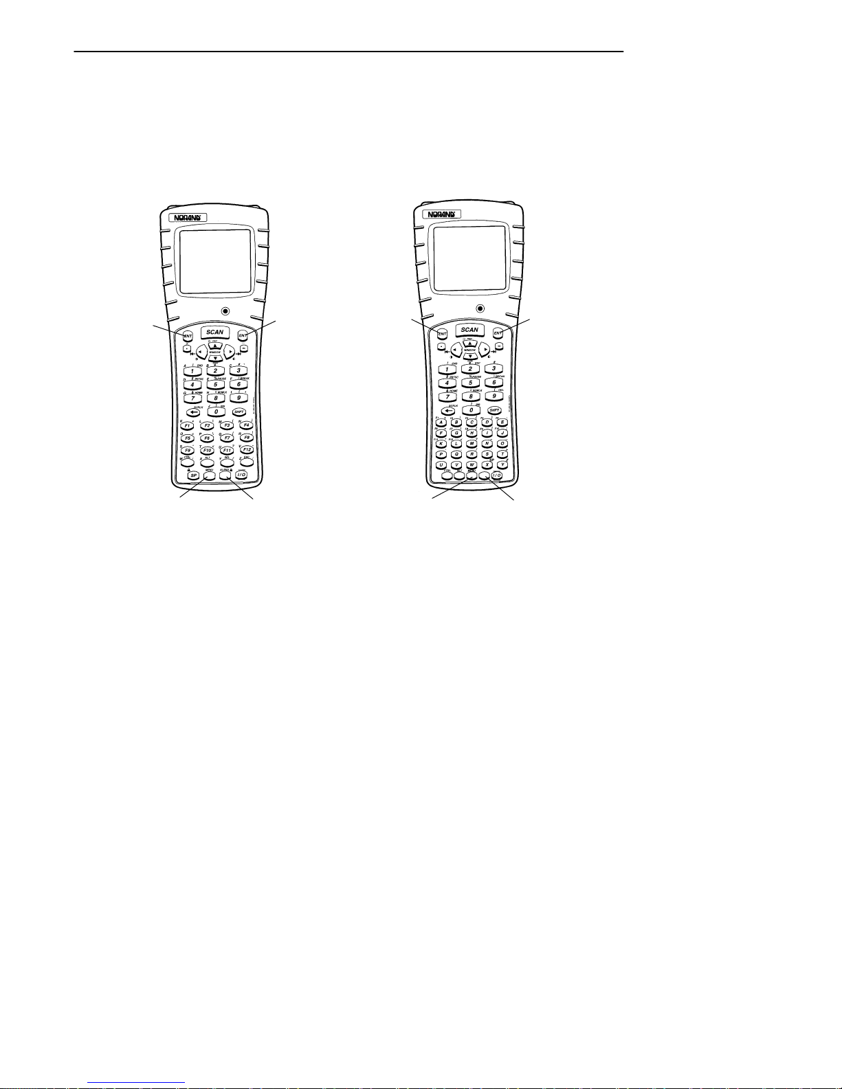
2. Perform the four finger reset (both Enter keys, blue
shift, and yellow shift keys) simultaneously. See
Figure 2-1 for location of keys.
3. Allow your computer to “boot” up and leave it suspended for 10 hours.
"
NOTE: Suspend means to press and hold the I/O key until the display goes
blank.
4. Insert a new and fully charged battery pack to begin
operations.
2-2 PEN*KEYRModel 6400 Hand-Held Computer User’s Guide
Page 60
SECTION 2 " Operation
41-Key Keyboard 51-Key Keyboard
4
3
1
2
1. Enter key
2. Yellow shift key
3. Blue shift key
4. Enter key
4
3
1
2
Resetting Your Computer
PEN*KEYRModel 6400 Hand-Held Computer User’s Guide 2-3
Figure 2-1
Page 61
SECTION 2 " Operation
Rechargeable Battery Labelling
9
WARNING: The battery can explode if it is incorrectly replaced. Replace
only with the same or equivalent battery type.
AVERTISSEMENT: La batterie au lithium peut exploser si elle est replacée de
manière incorrecte. Elle ne doit être remplacée que par une
batterie identique ou similaire.
WARNING: The lithium battery can explode if placed incorrectly in the
charger.
AVERTISSEMENT: Les batteries au lithium peuvent exploser ou prendre feu si
elles sont trop chargées à cause d’une mauvaise installation
de la station d’accueil.
2-4 PEN*KEYRModel 6400 Hand-Held Computer User’s Guide
Page 62
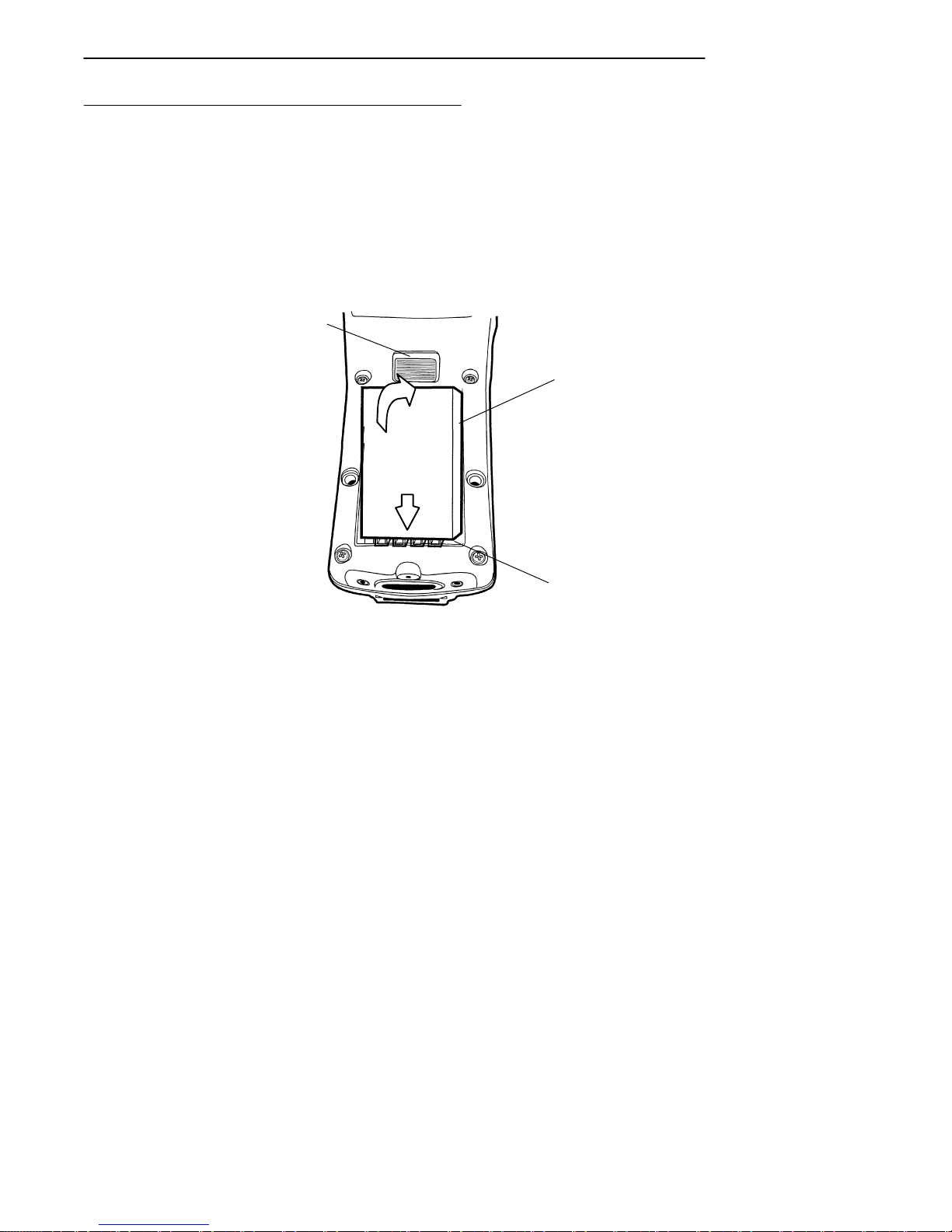
Installing the Main Battery
1. Position the battery pack with the contacts facing into
the battery compartment and the four protruding keys
hooking under the bottom end lip of the compartment
(see Figure 2-2).
2. Press in on the battery pack until it snaps into place.
3
SECTION 2 " Operation
2
1
1. Rechargeable battery pack (contacts on underside)
2. Battery compartment
3. Release latch
Figure 2-2
Installing Main Battery Pack
1
2
PEN*KEYRModel 6400 Hand-Held Computer User’s Guide 2-5
Page 63

SECTION 2 " Operation
Removing the Main Battery
Before you remove the main battery pack, ensure that your
computer is in a “Suspend” mode, meaning that the display
is blank. To suspend press the [I/O] key.
The steps on this page and 2-8 detail how to remove the
main battery and check how much power remains. Refer to
Installing the Main Battery on page 2-5 for replacing
the battery.
1. With your thumb, firmly push the release latch forward. Battery pops up and out of the compartment.
2. Lift battery out.
2-6 PEN*KEYRModel 6400 Hand-Held Computer User’s Guide
Page 64
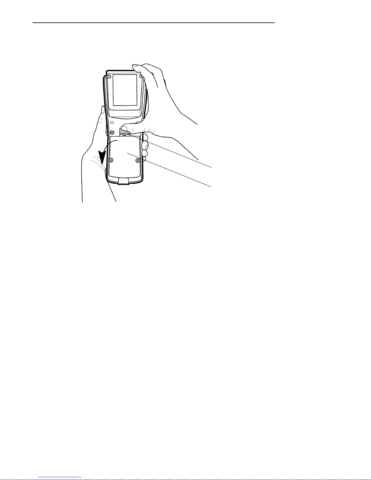
SECTION 2 " Operation
1
2
1. Release latch
2. Rechargeable battery pack (contacts on underside)
Figure 2-3
Removing Main Battery Pack
PEN*KEYRModel 6400 Hand-Held Computer User’s Guide 2-7
Page 65
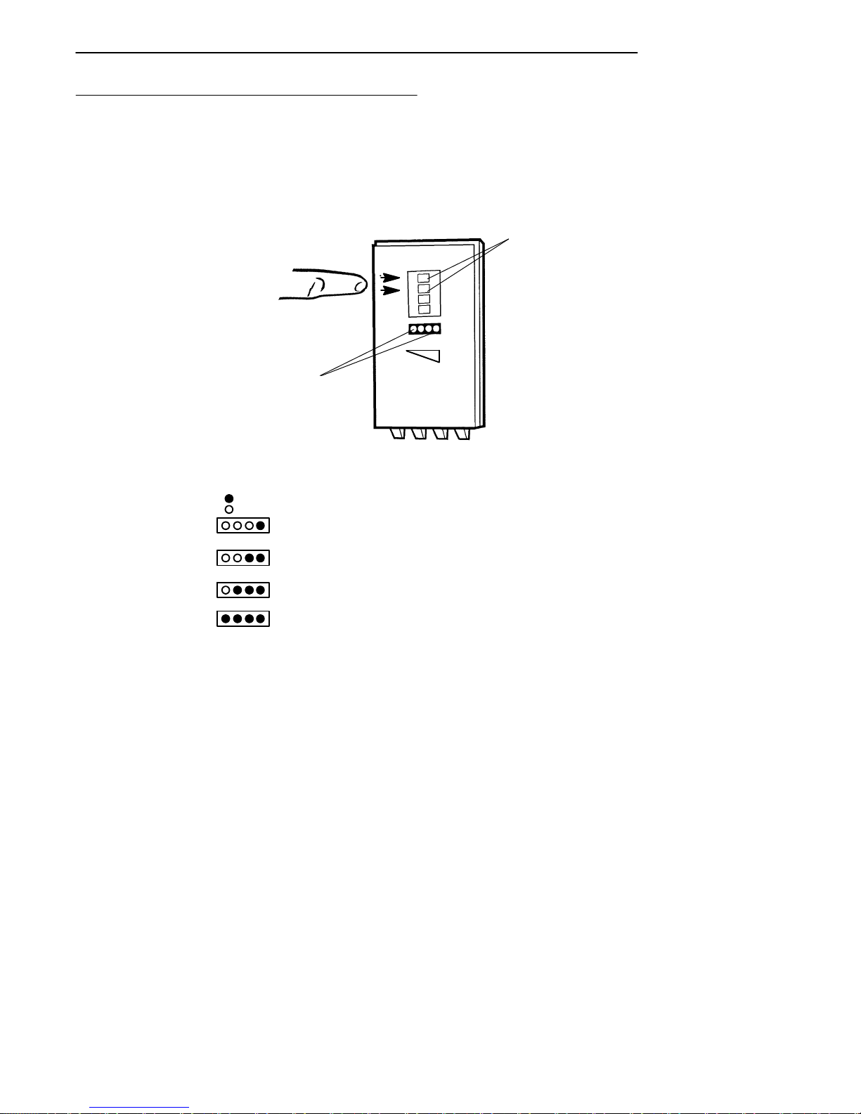
SECTION 2 " Operation
Measuring Battery Pack Charge Level
1. Touch your finger across the first two contacts.
2. Charge level is displayed from right to left. The higher
the battery charge level the more LEDs light.
1
2
1. Contacts for measuring charge level
2. LEDs that show charge level; see below for meaning
= LED on
= LED off
one LED = 21--25% charge level;
two LEDs = 26--50% charge level;
three LEDs = 51--75% charge level;
four LEDs = 76--100% charge level
Figure 2-4
Main Battery Pack Underside View Showing Contacts
3. Once your computer get below the 20% range, the
icons are replaced on the display with Ls and after the
level is less than 10% your computer emits a series of
beeps. Refer to Section 1 page 1-18 for the explanation of these Ls and beeps.
2-8 PEN*KEYRModel 6400 Hand-Held Computer User’s Guide
Page 66

Charging Your Battery Pack
Charging your battery pack can be done either in your
hand-held computer or in a charger. The following devices
provide charging while your computer is inserted into them:
In Your Hand-Held Computer
" 6400 Series multidock
" 6400 Series single dock
" 6400 Series vehicle dock
The multidock, single dock, and vehicle dock installation
and instructions are contained in a separate NORAND
publication 6400 Series Docks Installation Instructions
NPN: 962-020-004.
Using the optional Communication Adapter allows you access to charging your hand-held computer by using:
SECTION 2 " Operation
R
" An ac wall charger
" A cigarette lighter adapter
PEN*KEYRModel 6400 Hand-Held Computer User’s Guide 2-9
Page 67
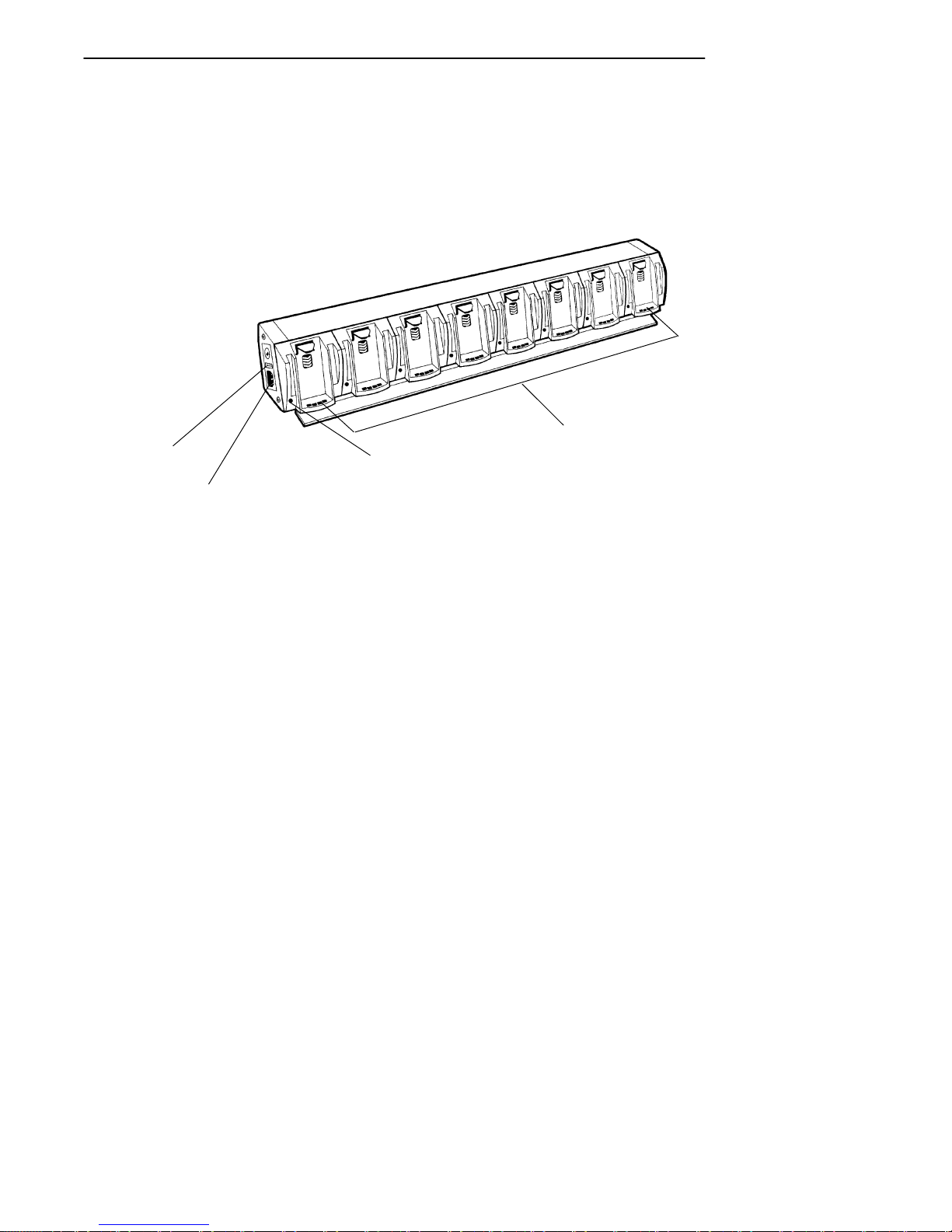
SECTION 2 " Operation
In An External Source
Figure 2-5 shows a multipack charger and Figure 2-6 shows
a single pack charger.
4
3
1
2
1. Battery pack compartments (eight)
2. Charge indicator LED
3. Power cord connector
4. Fuse holder
Figure 2-5
Multipack Charger
2-10 PEN*KEYRModel 6400 Hand-Held Computer User’s Guide
Page 68
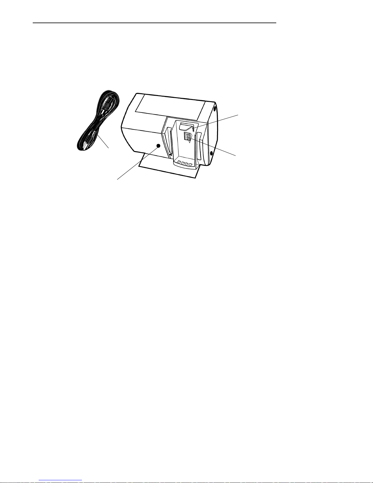
SECTION 2 " Operation
1
4
3
1. Battery pack compartment
2. Charger contacts
3. Charging indicator LED
4. Power cord
2
Single Pack Charger
PEN*KEYRModel 6400 Hand-Held Computer User’s Guide 2-11
Figure 2-6
Page 69

SECTION 2 " Operation
Battery Charger LED and Error Codes
When your battery pack is placed in a multipack or single
pack charger, the charger’s LED indicates the battery pack
charging status:
" Red indicates that the battery is charging.
" Green indicates the battery pack is fully charged.
" A combination of a blinking red and orange LED can
indicate one of two basic conditions: Either a bad connection, in which case you need to remove and reinsert
the battery pack into the charger, or there is a faulty
battery that needs to be replaced. However, the indicator can also alert you of a more serious charging or
product error. Table 2-1 and Table 2-2 on page 2-12
show you this more extensive list of error codes and
the solution notes.
Charging Indicator Error Codes
Table 2-1
Charging Indicator Error Codes
First
Blink
Orange Orange Orange Off High Voltage Fault 1 and 2
Red Orange Red Off No Communication 1
Orange Red Red Off Checksum Error 1
Red Red Red Off Upper Cell Mismatch 1 and 3
Red Red Orange Off Lower Cell Mismatch 1 and 3
Red Orange Orange Off 5 Bad Packets Re-
Orange Red Orange Off Wrong Battery Type 1
2-12 PEN*KEYRModel 6400 Hand-Held Computer User’s Guide
Second
Blink
Third
Blink Pause Description Solution Notes
1
ceived
Page 70

SECTION 2 " Operation
Table 2-2
Solution Notes
Note Solution
1 To isolate the issue to the battery pack itself, put the “suspected” battery
pack into a computer and operate for a few minutes. Then, try the
battery pack in different charger cups to see if this error still occurs. If it
does occur, send the battery pack to your service center for replacement.
2
3 Leave the battery pack in the charger for a minimum of 16 hours. If the
This situation could be caused by a bad charger cup or a computer.
Insert different batteries into this same charger cup. If the cup produces
this same error with the other batteries, this indicates that the cup on
the charger is bad. To get the battery back into a good state, put the
battery pack back in the computer and operate for a few minutes. Then
place the battery pack into a different charger cup and recharge. Send
the charger to your service center.
error condition still exists, send the battery pack to your service center.
Backup Battery
A fully charged backup battery provides protection for
maintaining data approximately 100 hours with the main
battery removed or completely run down. The backup
battery is charged from the main battery pack and every
time your hand-held computer is placed in a dock or
charging source.
"
NOTE: Your computer should be placed on a charging source for 12 hours
before using the first time to fully charge the backup battery.
The backup battery is not user-replaceable. To have your
backup battery replaced, send it in to the Norand Customer
Service Center nearest to you. Whenever you send in your
hand-held computer for service, include a description of
what you would like to have done to it.
PEN*KEYRModel 6400 Hand-Held Computer User’s Guide 2-13
Page 71

SECTION 2 " Operation
Downloading Programs To Your
Hand-Held Computer
Downloading parameters, program data, or inventory is
done by placing your hand-held computer into a dock,
through the IrDA port, or through the connector on the optional Communication Adapter endcap. The docking devices not only transmit data between your hand-held computer and the host, but also provide charging for your
hand-held computer.
Programming the Flash
The flash drive (c:\) is readable and writeable; therefore,
you can modify, create and delete files, etc. as your needs
demand. The PEN*KEYRModel 6400 Programmer’s
Reference Guide NPN: 977-054-004 contains the complete
details for programming flash. The upper 256 KB of flash
is reserved for the BIOS and DOS files. If this area ever
needs updating you will be furnished with complete
instructions along with the updated files.
2-14 PEN*KEYRModel 6400 Hand-Held Computer User’s Guide
Page 72

SECTION 2 " Operation
Turning Your Hand-Held Computer On
and Off (Suspending)
Turning On Your Hand-Held
Computer
Turn your hand-held computer on by pressing and releasing
the [I/O] key. When your hand-held computer is cold booted
(turning on the first time or after resetting), it displays several messages in rapid succession. The first message shows
the firmware version and its release date (DD/MMM/YY).
If you are just resuming, the display is restored to its previous state.
The screens that follow depend on your application. The
documentation that addresses using this hand-held computer as a batch (store now and send later) unit instruct you
about all remaining operations.
Suspending Your Hand-Held
Computer
To suspend operation, press and release the [I/O] key once.
Suspending operation works only if your computer is not
plugged into a charging source. The memory contents are
protected when the power is suspended.
Automatic Suspend
Your hand-held computer automatically puts itself into the
suspend mode after a period of inactivity. However, waiting
to suspend uses battery energy. Therefore it is best to
manually suspend your hand-held computer by pressing the
[I/O] key when not entering data. The memory contents are
protected when the power is suspended.
PEN*KEYRModel 6400 Hand-Held Computer User’s Guide 2-15
Page 73

SECTION 2 " Operation
Terminal Emulation programs do not automatically suspend. When lying idle but not manually suspended, the integrated radio module is still active and will drain battery
much as if it is actively being used. Therefore, it is necessary to manually suspend your computer by pressing the
[I/O] key.
Understanding the Key Clicks
You communicate your intended action to your hand-held
computer through pressing a key on the keyboard. Your
hand-held computer communicates back to you through an
audible response, a “key click.”
Each time you press a key, your hand-held computer lets
you know with a single audible key click. Pressing certain
keys causes two consecutive key clicks that occur one after
another so quickly that they almost sound like a single
beep. These two consecutive key clicks occur because your
hand-held computer automatically “presses” the shift key
for you in these cases.
EXAMPLE: An example of consecutive key clicks is the same as what happens
when you use the “shift” key on a PC. These keys include a colon(:),
double quote(”), and percent sign(%).
If you enter an incorrect action or keystroke, you hear a
“beep.” An error “beep” is longer than a key click. An error
“beep” is intended to get your attention and let you know an
error occurred.
2-16 PEN*KEYRModel 6400 Hand-Held Computer User’s Guide
Page 74
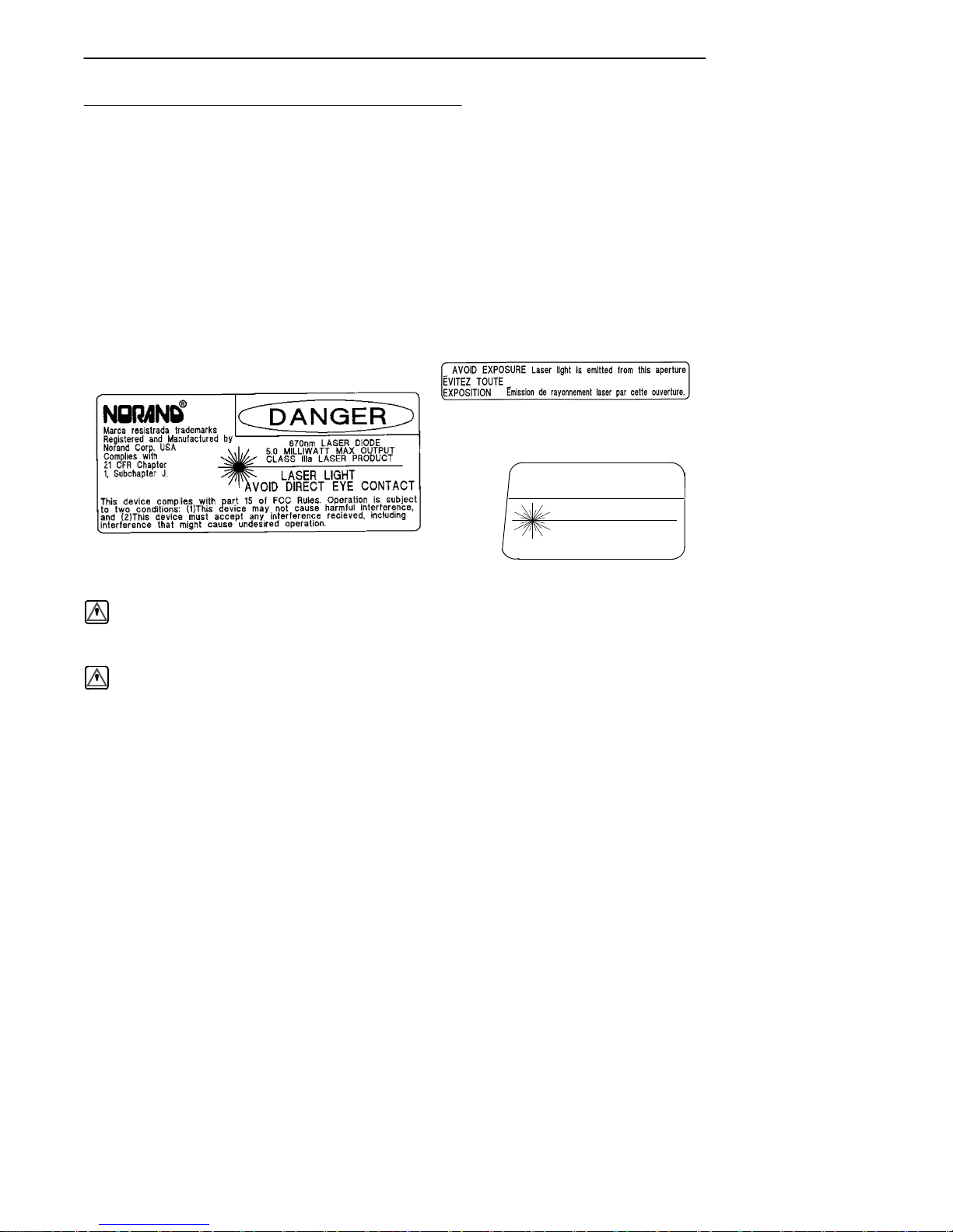
Scanning
SECTION 2 " Operation
You can order an integrated scanner as part of your handheld computer, or you can attach a tethered 5-volt serial,
decoded out bar code scanner to your hand-held computer.
Scanners allow the terminal to read and interpret bar
codes.
Using an Integrated Scanner
Label located on laser scanner lens
CAUTION
LASER LIGHT
DO NOT STARE INTO BEAM
670 nm LASER DIODE
1.0 MILLIWATT MAX OUTPUT
Class IIIa laser label located on bottom side of computer
CLASS II LASER PRODUCT
Class II Label
WARNING: Do not point the scanner at someone’s eyes or look directly into
it when scanning.
AVERTISSEMENT: Ne regardez pas la fenêtre du scanner lorsque vous
effectuez une scannérisation. Ne pointez jamais le rayon
laser vers les yeux de quelqu’un.
If your hand-held computer has been ordered with an internal integrated scanner, you can scan and key data on your
hand-held computer. More complete details for setting up
the parameters and operating the integrated scanner are
contained in the PEN*KEYRModel 6400 Programmer’s
Reference Guide NPN: 977-054-004.
PEN*KEYRModel 6400 Hand-Held Computer User’s Guide 2-17
Page 75
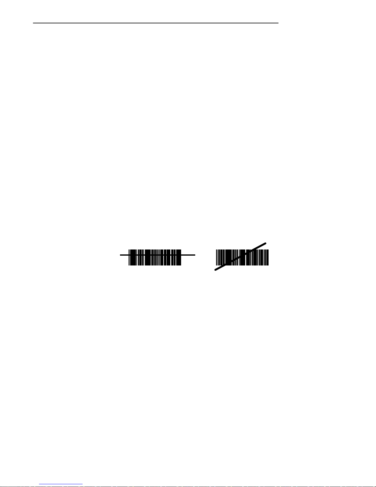
SECTION 2 " Operation
To use the integrated scanner, simply point the top of your
unit at the bar code, press the [SCAN] key and listen for
the beep acknowledging a good scan. A short high-tone
beep indicates a good scan. If you hear no beep, scan the
bar code again. If you are still not getting a “good scan”
beep, follow these instructions.
1. Ensure you are positioning the scan lens properly
across the bar code.
2. The scan beam must cross every bar and space on the
symbol.
3. Hold the scanner farther away for larger symbols.
4. Hold the scanner closer for symbols with bars that are
close together.
"
NOTE: Tip: After reading a bar code, aim the lens away from the bar codes
and press the SCAN key within 1/2 second, to get the laser beam
back on. With the laser beam on, you have five seconds to find and
scan the next bar code.
RIGHT WRONG
012345
2-18 PEN*KEYRModel 6400 Hand-Held Computer User’s Guide
012345
Page 76
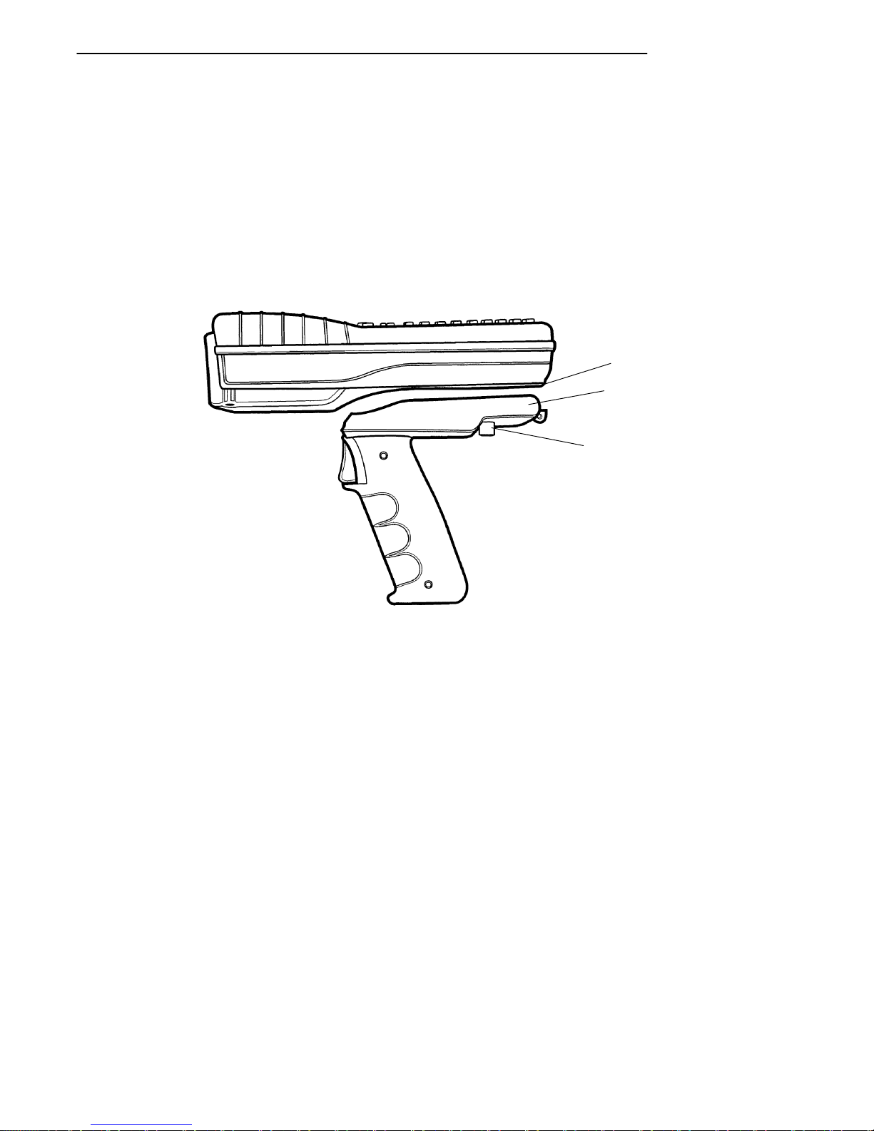
SECTION 2 " Operation
Installing the Optional Scanning
Handle
To attach the handle:
1. Slip the handle onto the base of your hand-held computer.
2. Secure the two quarter-turn screws.
3
1
2
1. Bottom of hand-held computer
2. Scanner handle
3. Quarter-turn screw fasteners
Figure 2-7
Optional Scanner Handle
PEN*KEYRModel 6400 Hand-Held Computer User’s Guide 2-19
Page 77
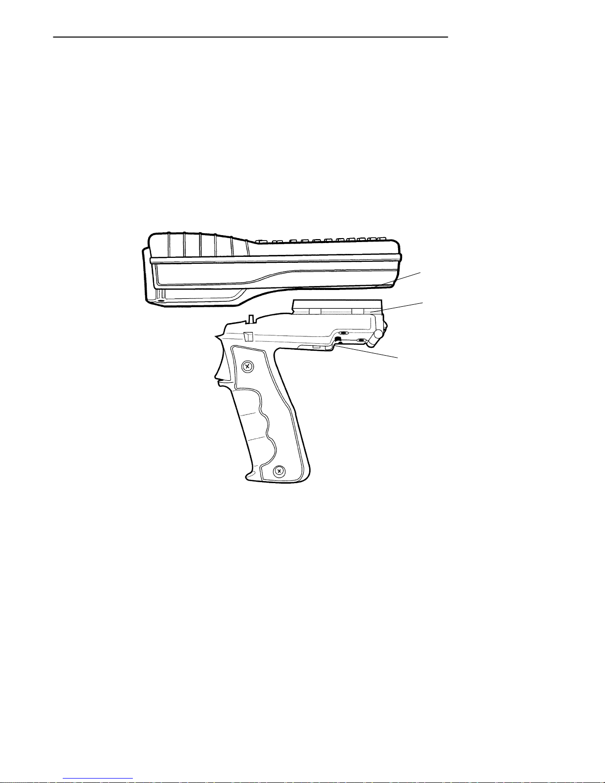
SECTION 2 " Operation
Installing the Optional Scanning
Handle with Battery Pack
To attach the handle:
1. Slip the handle onto the base of your hand-held com-
2. Snap into place.
3. To remove the handle, push in on the release button
puter.
and lift off.
1
2
1. Bottom of hand-held computer
2. Scanner handle with battery pack
3. Button to release handle from computer
Figure 2-8
Optional Scanner Handle with Battery Pack
2-20 PEN*KEYRModel 6400 Hand-Held Computer User’s Guide
3
Page 78
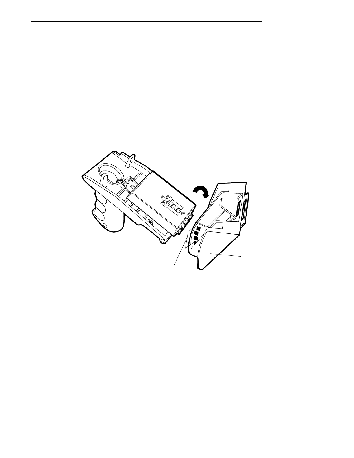
SECTION 2 " Operation
Charging the Scanner Handle
Batteries
To charge the batteries in the scanner handle:
1. Unscrew the two quarter-turn screws securing the
handle to the hand-held computer. Remove the handheld computer.
2. Slide the handle into the charger by inserting the keys
of the handle into the notches in the charger. The
single unit charger’s LED illuminates green when the
battery pack is fully charged.
1
2
1. Charger
2. Notch outs in battery pack charger cup
Figure 2-9
Inserting Scanner Handle Into Charger
PEN*KEYRModel 6400 Hand-Held Computer User’s Guide 2-21
Page 79

SECTION 2 " Operation
Using a Tethered Bar Code Scanner
The tethered bar code scanner attaches to your computer at
the 9-pin D-sub connector located on the bottom of the optional Communication Adapter. The computer provides the
power to run the scanner.
Your hand-held computer supports the serial, decoded tethered scanners in the Norand product line, these include:
Tethered Scanner Supported
Symbol Scanners
" LS-3203ER-I200A, Extended Range part number
858-042-800
" LS-3603-I200A Fuzzy Logic part number 858-079-901
Cable:
" Straight screw on connector serial cable 321-518-001
PSC Scanners
" PSC5300 IP Series Standard Range part number
858-065-012
" PSC5300 IP Series VIN part number 858-065-022
" PSC5300 IP Series Long Range part number
858-065-052
" PSC5300 IP Series Extra Long Range part number
858-065-072
" PSC5300 IP Series Ultra Long Range part number
858-065-092
" PSC5300 IP Series Long Range High Power part num-
ber 858-065-152
" PSC5300 IP Series Extra Long Range High Power
part number 858-065-172
2-22 PEN*KEYRModel 6400 Hand-Held Computer User’s Guide
Page 80
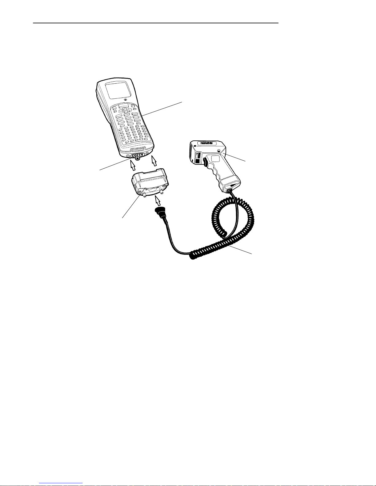
SECTION 2 " Operation
Cable:
" Straight screw on connector serial cable 321-476-082
1
5
2
4
3
1. 6400 Hand-held computer
2. Scanner
3. RS-232 scanner cable
4. Communication adapter
5. Communication adapter connector
Figure 2-10
Connecting a Tethered Scanner
PEN*KEYRModel 6400 Hand-Held Computer User’s Guide 2-23
Page 81

SECTION 2 " Operation
Software
The software that supports tethered scanning is V1.15+
BIOS and V5.10+ terminal emulations.
Tethered scanning is supported for any external device that
sends its serial data at 9600 baud, 8 data bits, no parity, 1
stop bit with an ASCII STX (hex 02) before the data and an
ASCII ETX (hex 03) after the data. No protocols, such as
ACK/NAK, RTS/CTS, or XON/XOFF, are supported. All
8-bit characters between the STX and ETX will be stuffed
in the PC BIOS key buffer.
Setting Terminal Emulation to
Accept Tethered Laser Scanners
1. In AUTOEXEC.BAT, ensure the scanner driver is
2. From the Terminal Emulation mode, press the yellow
3. Select option 1) Set-up Parms.
4. Enter password CR52401.
5. Select option 2) Barcode Parms.
6. At Scanner Type menu select 3) Laser and press ENT
7. At Main Menu select 4) Tests
8. At Tests menu select 1) Peripherals
9. At Peripherals menu select 5) Scanner Test
If you experience problems with using your laser scanner
with terminal emulation try these steps:
loaded with 64SCN7B --T1 --I0
and then the blue keys to enter the Terminal Emulation Main Menu.
five times.
1. Reboot to the DOS prompt <YELLOW--BLUE--ENT-ENT> press 0 at pause.
2. Type DEL CONFIG.DAT press ENT.
2-24 PEN*KEYRModel 6400 Hand-Held Computer User’s Guide
Page 82

SECTION 2 " Operation
3. Press CTRL ALT DEL to reboot.
Setting Your DOS Application to
Accept Tethered Laser Scanners
In AUTOEXEC.BAT, ensure the scanner driver is loaded in
the PS/DOS section with 64SCN7B --E --W --T1 I0 (this is
for wedge scanning).
Setting Up Your LS3203 or LS3603
RS-232 Serial Scanner Parameters
Tethered laser power is always on, so a tethered laser can
scan, decode, and send the data as soon as it is connected,
even when it is not properly configured. Therefore, proper
operation of the tethered laser is no indication that the laser is correctly configured for the scanner driver 64SCN7B.
Scan the following bar codes to set up your LS3203ERI200A or LS3603-I200A scanner so it will work with your
hand-held computer. You need to scan all the bar codes (except for the Host Transmit Code ID Character and Host Decode Options) to enable your laser scanner to work with the
64SCN7B scanner driver on your hand-held computer.
Set All Defaults
Scan the Set All Defaults bar code to set up your scanner
for RS-232 serial communication.
PEN*KEYRModel 6400 Hand-Held Computer User’s Guide 2-25
Page 83

SECTION 2 " Operation
Data Transmission Format
1. Scan the <PREFIX><DATA><SUFFIX> bar code.
<PREFIX><DATA><SUFFIX>
2. Scan the PREFIX bar code.
3. Scan the PREFIX values 1,0,0,2 bar codes from page
PREFIX
2-27. If you make a change or wish to change your
selection, scan CANCEL.
4. Scan the SUFFIX bar code.
5. Scan the SUFFIX values 1,0,0,3 bar codes from page
2-27. If you make a change or wish to change your
selection, scan CANCEL.
SUFFIX
2-26 PEN*KEYRModel 6400 Hand-Held Computer User’s Guide
Page 84
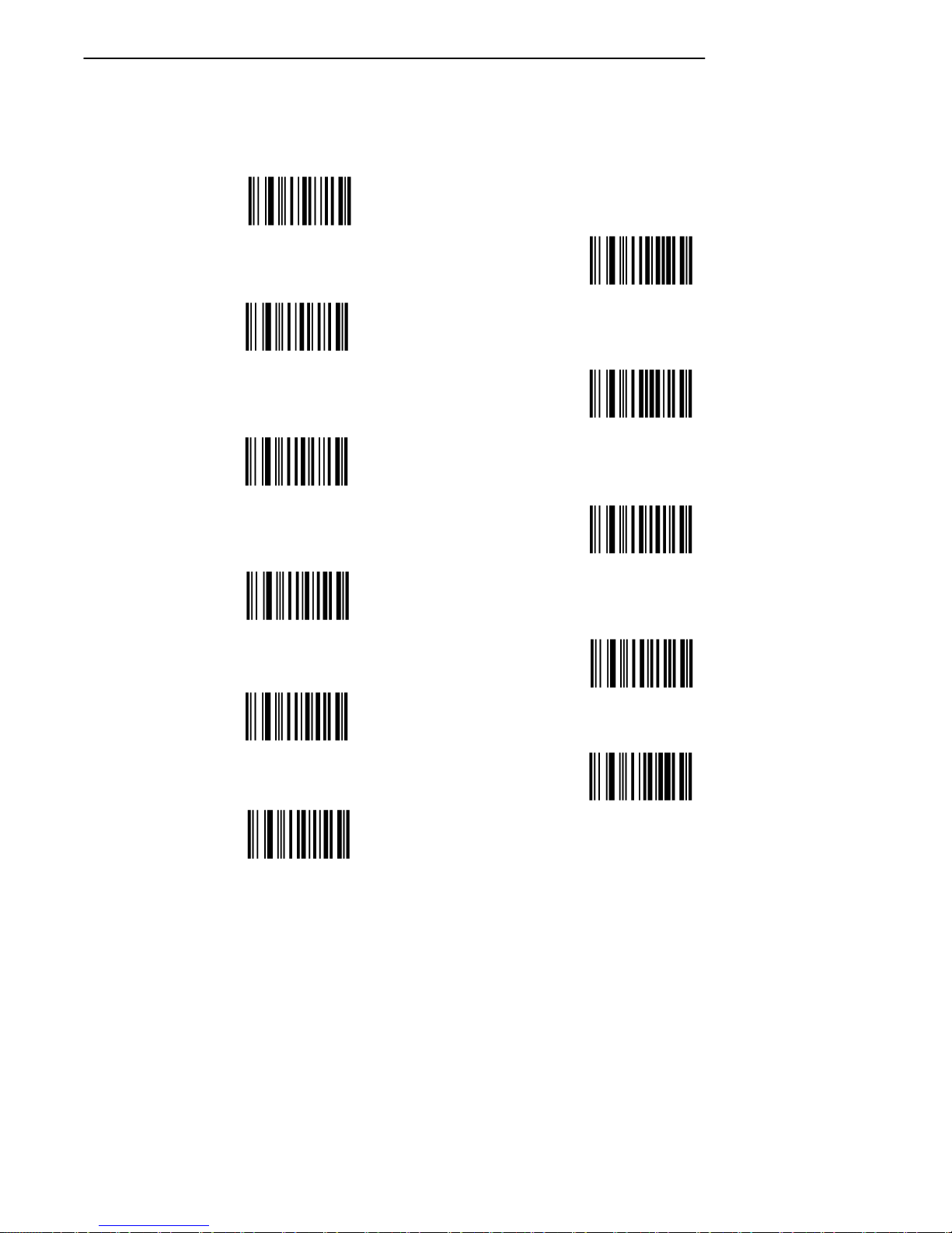
SECTION 2 " Operation
RS-232 Host Prefix/Suffix Values
0
6
1
7
2
8
3
9
4
CANCEL
5
PEN*KEYRModel 6400 Hand-Held Computer User’s Guide 2-27
Page 85

SECTION 2 " Operation
RS-232 Host Parity
NONE
RS-232 Host Stop Bit Select
1 STOP BIT
RS-232 Host ASCII Format
8-BIT
2-28 PEN*KEYRModel 6400 Hand-Held Computer User’s Guide
Page 86

SECTION 2 " Operation
RS-232 Host Transmit Code ID Character
(Optional)
Select to enable or disable this setting. The default is
Transmit Code ID Character. The Transmit Code ID Character must be enabled if you are using FWP640H0 or
FWP640H4 terminal emulation software in your hand-held
computer.
TRANSMIT CODE ID CHARACTER
DO NOT TRANSMIT
CODE ID CHARACTER
RS-232 Host Decode Options (Optional)
Scan one of these bar codes to enable or disable the laser
beep after a good scan. If your hand-held computer application beeps when it gets scanner data then you would probably want to disable the laser beep.
DO NOT BEEP AFTER
GOOD DECODE
BEEP AFTER
GOOD DECODE
PEN*KEYRModel 6400 Hand-Held Computer User’s Guide 2-29
Page 87

SECTION 2 " Operation
Problems with Your Scanner
If you are having problems with your scanner:
1. Refer to the user guide for your scanner.
2. Refer to the PEN*KEYRModel 6400 Programmer’s
3. Call your Norand 24-hour Customer Response Center
Reference Guide NPN: 977-054-004
at 1-800-221-9236.
2-30 PEN*KEYRModel 6400 Hand-Held Computer User’s Guide
Page 88

Section 3
Terminal Emulation Menu Screens
" " " " " " " " " " " " " " " " " " " " " " " " " " " "
Introduction
The Terminal Emulation Menu Screens are provided to support terminals running NORANDRTerminal Emulation
software. This section describes the menus used to set operating and scanning parameters for the hand-held computer. Additional information can be found in the programmer’s guide or technical overview for your particular
emulation program.
Keyboard Functions
Some keys on the hand-held computer have special functions, which can vary depending upon the application software. General function keys (keys that perform the same
task, regardless of the application) are described in the following paragraphs.
Yellow and Blue Shift Keys
Use the yellow and blue shift keys to put the keyboard in
the desired (yellow or blue) shift mode. These shifted key
functions are shown on the keyboard overlays in Appendix
C.
PEN*KEYRModel 6400 Hand-Held Computer User’s Guide 3-1
Page 89

SECTION 3 " Terminal Emulation Menu Screens
ENTER [ENT] Keys
Press either [ENT] key to select the option that is highlighted in the menu shown on the display. After selecting
an option [ENT] either restores the display to the previous
menu or advances to the next menu.
Number Keys [0] Through [9]
Many menus have numbered options. To choose a particular option, press the numeric key that corresponds to that
option.
Once you make a selection and you remain at that menu
screen, the option is highlighted, but you can select additional options. To deselect an enabled option, press the
number corresponding to that option.
In some cases, pressing a number brings up a different
menu (submenu). This allows you to further modify the
choice made in the parent menu. Press the [ENT] key to
confirm the settings and exit this menu.
After the modification(s), you may (depending on the menu
and function) be permitted to return to the parent menu to
make additional selections. There are also situations where
pressing [6] causes your hand-held computer to exit from a
submenu or reboot.
Various menus require entering a number, but do not necessarily have simple choices such as 1, 2, 3, 4, etc. Instead,
you may have to enter a number from a range (example:
0--32). You may have to press [ENT] after these.
These instances are detailed in the text that applies to
those menus, or in the menu displays.
3-2 PEN*KEYRModel 6400 Hand-Held Computer User’s Guide
Page 90

SECTION 3 " Terminal Emulation Menu Screens
Y Up and B Down Arrows
These keys are defined by the host computer. Use these
keys to:
" Adjust the length and frequency of the key click and
error buzzers.
" Set the display size (the number of rows displayed
and characters per row) of the display.
Display Annunciators
Annunciators show the current status or operation in progress. The following lists some of the annunciators common
to all emulations. These annunciators occupy positions 0
through 8 of the display. A bibliography follows that tells
where more information can be found.
Display Position 0
Radio computer. The radio is transmitting data to the
base station.
Display Position 1
If the radio icon is displayed in position 0 then position 1
shows the status of the radio transmission (either receiving,
sending, communication loss, or message waiting). If there
is no radio icon shown in position 0 then this position is
blank and position 1 shows the active session number 1 or
2.
Sending. Radio is sending data to the base station.
Receiving. Radio is receiving data from the base station.
This annunciator appears only when the information is for
this particular computer’s address.
PEN*KEYRModel 6400 Hand-Held Computer User’s Guide 3-3
Page 91

SECTION 3 " Terminal Emulation Menu Screens
Communications loss. No communication with the host
computer has occurred for at least 60 seconds. The radio
computer may be out of radio range, the base station may
not have power, or communications from the host computer
to the base station may not be properly set up.
Message. You have received a message and it has not been
read.
Display Position 2
X
^
Input Inhibited. The keyboard has accepted enough information for the current input field. If the “key ahead” feature is on, the terminal stores the keystrokes made after
“input inhibited” appears. The host may also inhibit (lockout) the keyboard upon certain errors or when sending
additional information to your computer.
Insert Mode. Characters are inserted, not overwritten.
Display Position 3
Y
A
"
Alphabet Character (green) Shift Mode. The keyboard
is in the alphabet character shift mode—any alphabet character keystrokes are entered as uppercase characters.
(blue) Shift Mode. The keyboard is in a colored shift
mode—keystrokes enter the symbol or perform the function
shown on the overlay just to the upper left of the key.
(yellow) Shift Mode. The keyboard is in a colored shift
mode—keystrokes enter the symbol or perform the function
shown on the overlay just to the upper right of the key.
Display Position 4
Alpha Lock. This Alpha Lock symbol is used only for the
A
3-4 PEN*KEYRModel 6400 Hand-Held Computer User’s Guide
41-key keyboard model.
Page 92

SECTION 3 " Terminal Emulation Menu Screens
Display Positions 5-8
Battery Pack Gas Gauge Icons:
These battery icons represent the charge level in your main
battery pack.
" Four icons (positions 5--8) indicates more than 76 %
charge level
" Three icons (positions 5, 6,, and 7) indicates between
51--75%
" Two icons (positions 5, and 6) indicates between
26--50%
" One icon (position 5) indicates between 21--25%
Once your computer gets below the 20% range, the icons are
replaced by “Ls” and after the charge level is less than 10%
your computer emits a series of beeps.
" Four Ls indicates between 16--20% charge level
" Three Ls indicates between 11--15%.
" Three Ls indicates between 11--15%. At the 15%
charge level, your computer beeps once. The sound
duration and frequency are at levels you have set for
your computer.
" Two Ls indicates between 6--10%. At the 10% and 7%
charge levels, your computer beeps once. The sound
duration and frequency are at levels you have set for
your computer.
" One L indicates between 0--5%. At this charge level,
your computer beeps three times at its current setting
level for both duration and frequency.
"
NOTE: If you have the beeper turned off, you will not hear any of the low
battery beep warnings.
The battery pack icons on your computer display reflect the
same status as the LEDs on the battery pack. However,
there may be a one minute delay for updating the icons on
the display when the battery pack is replaced.
PEN*KEYRModel 6400 Hand-Held Computer User’s Guide 3-5
Page 93

SECTION 3 " Terminal Emulation Menu Screens
Again, these are just a few of the display annunciators that
are common to all emulations. There are others, specific to
individual emulations, that are not shown here.
Annunciator bibliography (emulation/reference source/
Norand Part Number):
" VT220/ANSI Terminal Emulation Programmer’s Ref-
erence Guide. (NPN 977-047-037)
" 5250 SNA and Asynchronous Terminal Emulation
Programmer’s Reference Guide. (NPN 977-047-039)
" 3270 Terminal Emulation Programmer’s Reference
Guide. (NPN 977-047-040)
" Native Async Terminal Emulation Programmer’s Ref-
erence Guide. (NPN 977-047-038)
Setting the Operating Parameters
Make sure there is a fully-charged battery pack in the
hand-held computer before setting the parameters.
Opening the Main Menu
The Main Menu is the first screen displayed when you open
the hand-held computer menus. All other menus are
accessed from the Main Menu.
To open the Main Menu, press the yellow shift, then the
blue shift (MENU) key. Briefly, these keys generally operate as:
" Blue shift is for functions labeled by blue legends
above the keys.
" Green shift is for functions labeled by green legends
above the keys.
" Yellow shift is for functions labeled by yellow legends
above the keys.
3-6 PEN*KEYRModel 6400 Hand-Held Computer User’s Guide
Page 94

SECTION 3 " Terminal Emulation Menu Screens
" Blue then Green shift is CAPS LOCK.
" Blue then Yellow shift is Alphabetic Lock (41-key units
only).
" Yellow then Blue shift is Terminal Emulation menus;
your particular emulation software probably treat the
keys for contrast control, backlighting and other functions differently.
After the Main Menu appears, enter a number (1 through 7)
to make a selection. The Main Menu is shown below:
Main Menu
1) Set-up Parms
2) LCD Parms
3) Beeper Setup
4) Tests
5) Version Info
6) Exit Menus
7) More
PEN*KEYRModel 6400 Hand-Held Computer User’s Guide 3-7
Page 95
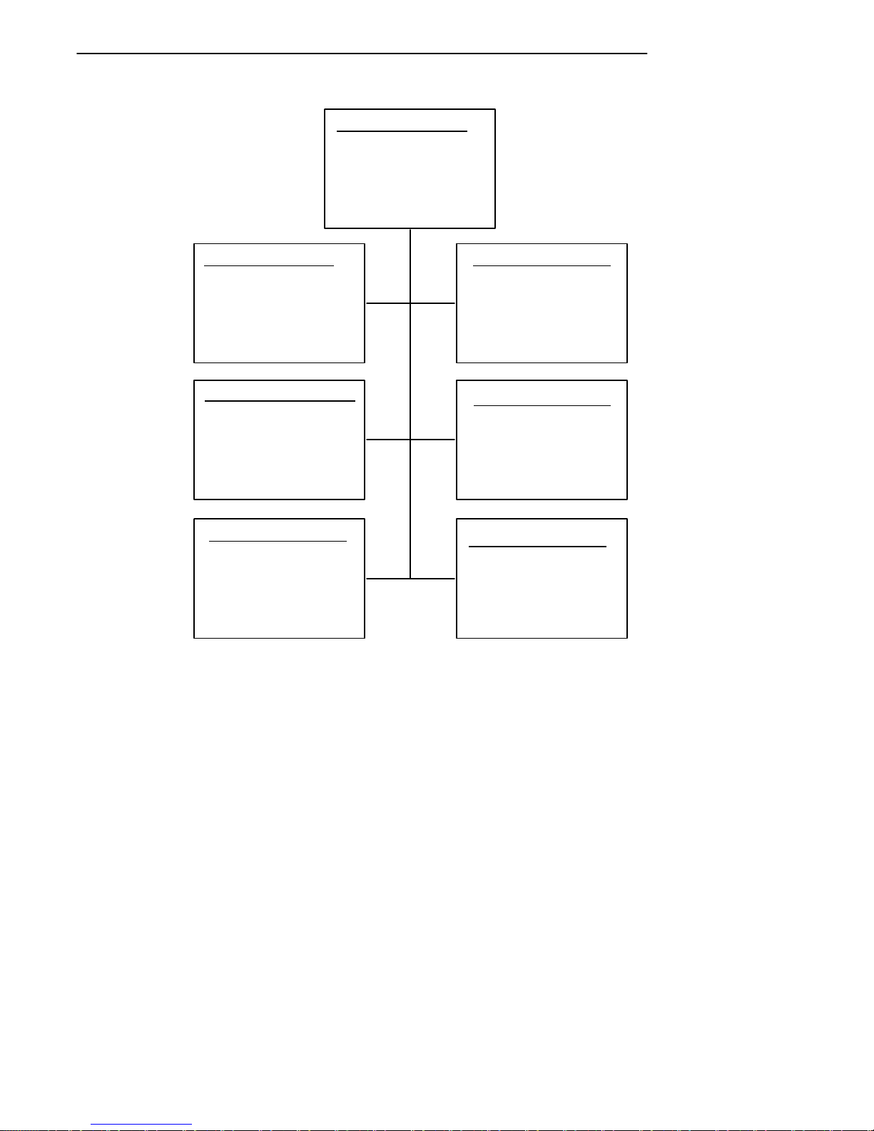
SECTION 3 " Terminal Emulation Menu Screens
Main Menu
1) Set-up Parms
2) LCD Parms
3) Beeper Setup
4) Tests
5) Version Info
6) Exit Menus
7) More
Set Parameters
1) Radio #
2) Barcode Parms
3) Protocol Opts
4) Display Opts
5) Radio Comm
6) Cold Start
7) More
Beeper Setup
1) Key Click
2) Error Tone
3) Beeper Select
Version Info
Firmware name
Version number
Date ddmmmyy
(1) (2)
(3) (4)
(5) (7)
LCD Parms
1)
2) Screen Size
3) Screen Mode
4) Annunciators
5)
6) Key Uppercase
7) Scroll Window
Tests
1) Peripherals
2)
3) Memory View
4) Packet Driver
5) Numbers
6) Timed Numbers
Main Menu 2
1) Keyboard Opts
2) Save Parms
3)
4) Session Menu
To return to the Main Menu from the hand-held computer
menus program, simply press the [ENT] key several times.
You can then select 6) Exit Menus, to return to the operating system.
3-8 PEN*KEYRModel 6400 Hand-Held Computer User’s Guide
Page 96

SECTION 3 " Terminal Emulation Menu Screens
The following paragraphs describe options available from
the Main Menu.
Set-Up Parms
The Set-up Parms (parameters) menu is password protected
to guard against unwanted changes or loss of data.
In this menu you can change the following:
" Radio identification number
" Bar code parameters
" Host and emulation mode options
" Display options
" Radio Comm (not user accessible at this time)
" Enable system security with a global password
Or, you can reboot your hand-held computer.
LCD Parms
LCD Parms (parameters) menu adjusts the following display (Liquid Crystal Display) parameters:
" Screen size (number of lines displayed and characters
per line)
" Cursor position (Screen Mode)
" Annunciators
" Uppercase display
" Scrolling window parameters
Beeper Setup
Beeper Setup lets you adjust the frequency and the length
(duration) of the buzzer. Different buzzer tones can be programmed, and you can select the buzzer output for the:
" Key click (indicating that a valid key has been pressed
or a good scan occurred)
" Error tone (indicating some error condition occurred;
for example, an unacceptable keystroke.)
PEN*KEYRModel 6400 Hand-Held Computer User’s Guide 3-9
Page 97

SECTION 3 " Terminal Emulation Menu Screens
Tests
The Tests menu allows you to perform the following tests:
" Peripherals
" Memory View
" Packet Driver
" Numbers
" Timed Numbers
Version Info
You can use the UP and DOWN arrow keys in the Version
Info menu to display:
" The type of program in FLASH ROM
" The release date of the program in FLASH ROM
Exit Menus
The Exit Menus option exits from the hand-held computer
menus and returns to the “initial” screen.
More
The More option opens a menu called Main Menu 2, which
lets you (1) set a keyboard “type-ahead” option, (2) save parameter settings as the new hand-held computer default
parameters, and (3) designate session switching parameters.
Opening the Set-Up Parms Menu
The Set-Up Parms (parameters) menu is password protected to prevent unauthorized persons from changing
hand-held computer parameters.
The parameters you set only apply to the current session.
If more than one session is available to you, use the Session
Menu (#4 in Main Menu 2) to verify or change the current
session before changing parameter settings.
3-10 PEN*KEYRModel 6400 Hand-Held Computer User’s Guide
Page 98

SECTION 3 " Terminal Emulation Menu Screens
To open the Set-Up Parms menu:
1. Press the [1] key.
2. Press the [ENT] key.
3. At the prompt, enter the password CR52401.
The Set-Up Parms menu, and the menus you can access
from it, are shown on the following page.
PEN*KEYRModel 6400 Hand-Held Computer User’s Guide 3-11
Page 99
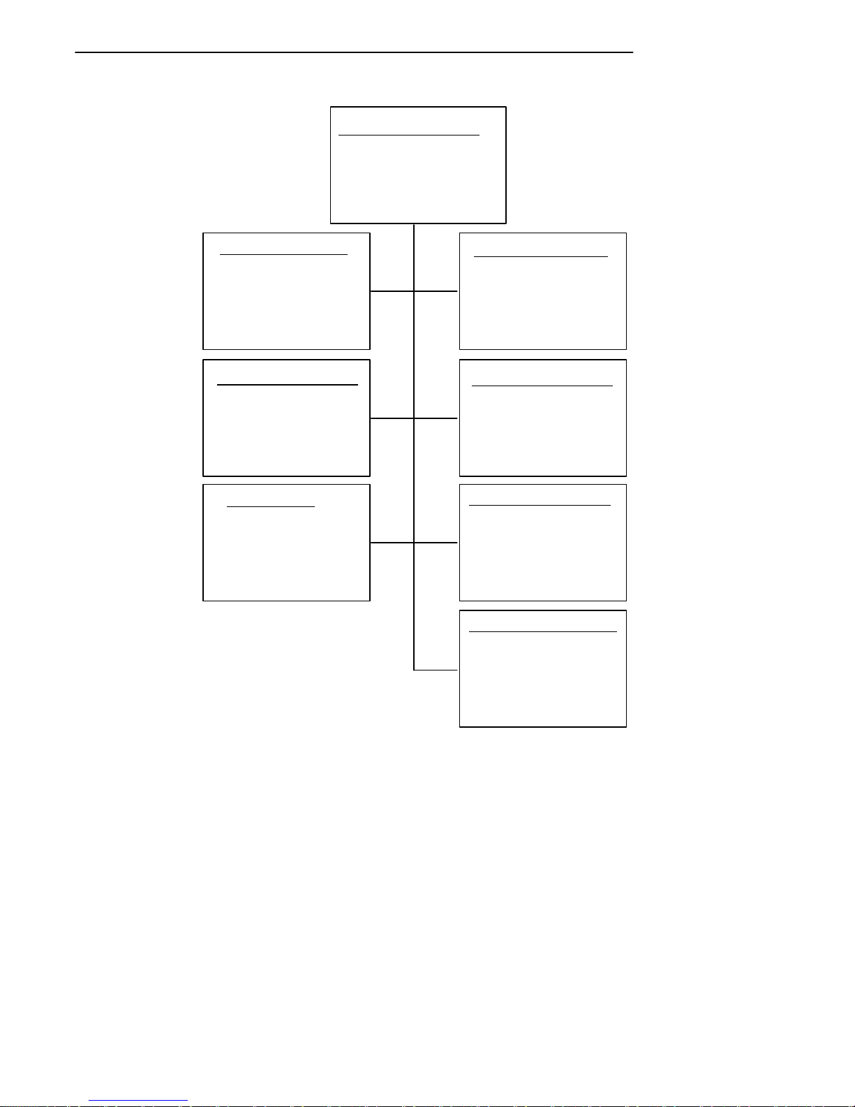
SECTION 3 " Terminal Emulation Menu Screens
1) Radio #
2) Barcode Parms
3) Protocol Opts
4) Display Opts
5) Radio Comm
6) Cold Start
7. More
Set-up Parms
Radio #
Enter Unit
Number:
xx
Press A for
Advanced Setup
Protocol Opts
1) Host View Size
2) Data Stream
3) Extended Cmds
4) 5250
5) 3270
6) VT220
7) Native
Protocol
1) SST
2) SST-Diag Mode
(1) (2)
(3) (4)
(5) (6)
(7)
Scanner Type
1) No Scanner
2)
3) Laser
4)
5)
Display Opts
1) Backlight
2) Cursor Mode
Cold Start
Enter “Y”
To Cold Start
terminal:
Set-up Parms
1) Menu Password
2) Print Device
3-12 PEN*KEYRModel 6400 Hand-Held Computer User’s Guide
Page 100

SECTION 3 " Terminal Emulation Menu Screens
Radio #
Use the Radio # menu to set, view, or change the hand-held
computer identification number. This number allows the
host computer to identify individual hand-held computers
in the radio data network. Each hand-held computer must
have a unique number in the same network.
The Set Radio # and the Advanced Setup menus, are shown
on the following pages.
To set or change the hand-held computer identification
number, use the numeric keys on the hand-held computer
keyboard. After entering a number (between 0 and 126),
press the [ENT] key to return to the Main Menu, or the [A]
key to go to the Advanced Setup menus.
The LAN ID number can be 0--255 depending on the radio
you are using. With the RM60/70 radio the number can be
0--255 and with the RM80/90 radio the range is 0--15. Your
computer only communicates with equipment using the
same ID number that you assigned to your LAN.
If you enter a LAN ID number that is different from what is
configured in your NET.CFG file you get this message.
LAN ID changed
Need to reboot
to take effect.
If this happens the system modifies your net.cfg file which
is used by the WTPPKT.EXE program on initialization of
your computer. Therefore, that is why you need to reboot
your computer.
PEN*KEYRModel 6400 Hand-Held Computer User’s Guide 3-13
 Loading...