

Page 1

User’s Manual
P/N 064673-004
Installation Utility (4MB)
®
JANUS
2.4 GHz
Page 2

Intermec Technologies Corporation
6001 36th Avenue West
P.O. Box 4280
Everett, WA 98203-9280
U.S. service and technical support: 1-800-755-5505
U.S. media supplies ordering information: 1-800-227-9947
Canadian service and technical support: 1-800-688-7043
Canadian media supplies ordering information: 1-800-268-6936
Outside U.S. and Canada: Contact your local Intermec service supplier.
The information contained herein is proprietary and is provided solely for the purpose of allowing
customers to operate and/or service Intermec manufactured equipment and is not to be released,
reproduced, or used for any other purpose without written permission of Intermec.
Information and specifications in this manual are subject to change without notice.
1998 by Intermec Technologies Corporation
All Rights Reserved
The word Intermec, the Intermec logo, JANUS, IRL, TRAKKER, Antares, Duratherm, Precision Print,
PrintSet, Virtual Wedge, and CrossBar are either trademarks or registered trademarks of Intermec
Corporation.
Throughout this manual, trademarked names may be used. Rather than put a trademark () symbol
in every occurrence of a trademarked name, we state that we are using the names only in an
editorial fashion, and to the benefit of the trademark owner, with no intention of infringement.
Page 3

Manual Change Record
g
y
y
This page records the changes to this manual, which was originally released as version 001.
Version Date Description of Change
002 12/96 New information was added for the JG2050 and for UDP Plus
terminal emulation.
003 9/97 New information was added to describe usin
on a JG2010.
004 7/98 Installation utilit
installation/configuration process.
software was modified to streamline the
the installation utilit
Page 4

Page 5

Contents
Contents
Before You Begin ix
Cautions and Notes ix
About This Manual ix
Other Related Manuals xii
Learning About the Installation Utility
1
2
Unpacking the Installation Utility Kit 1-3
What the Installation Utility Does 1-3
How the Installation Utility Works 1-4
Modifying the JANUS Drive Images 1-5
Drive C Image 1-5
Drive D Image 1-5
Downloading the New JANUS Drive Images 1-6
System Requirements 1-7
Host PC Requirements 1-7
Making a Backup Copy 1-7
Navigating Within Screens 1-8
Preparing to Run the Installation Utility
Why Read This Chapter? 2-3
Setting Up the Host PC 2-3
Creating a HOSTS File 2-3
Understanding Configuration Parameters 2-4
Terminal Selection Screen 2-4
Network/Protocol Selection Screen 2-4
Character Set Screen 2-5
About the Network Parameters 2-6
About the Radio Parameters 2-10
LAN WorkPlace for DOS Parameters 2-7
NetWare Client for DOS Parameters 2-8
FTP PC/TCP for DOS Parameters 2-9
v
Page 6

JANUS 2.4 GHz Installation Utility User’s Manual (4MB)
Shelling Out to DOS 2-12
Configuring Multiple JANUS RF Devices 2-13
Running the Installation Utility
3
4
Starting the Installation Utility 3-3
Configuring the First JANUS RF Device 3-3
Choosing the Configuration Parameters 3-3
Shelling Out to DOS to Modify the JANUS Drive Images 3-7
Downloading the Modified JANUS Drive Images 3-8
Configuring Multiple JANUS RF Devices 3-10
Restoring the Host PC to the Original Configuration 3-11
Troubleshooting
General Problems 4-3
Error Messages 4-4
Drive A Error Messages 4-8
Deleted, Modified, and New Files
A
vi
Deleted Files A-3
Files Removed From Drive C A-3
Files Removed From Drive D A-3
Modified CONFIG.SYS File A-4
JG2010 CONFIG.SYS A-4
JG2020 CONFIG.SYS A-6
JG2050 CONFIG.SYS A-8
Modified AUTOEXEC.BAT File A-10
JG2010 AUTOEXEC.BAT A-10
JG2020 AUTOEXEC.BAT A-12
JG2050 AUTOEXEC.BAT A-14
NET.CFG File A-16
JG2010 NET.CFG A-16
JG2020 NET.CFG A-17
Page 7

JG2050 NET.CFG A-18
About the NET.CFG Parameters A-20
PCTCP.INI File A-20
NET.BAT File A-22
JG2010 NET.BAT for NetWare Client A-22
JG2010 NET.BAT for LanWorkplace A-22
JG2010 NET.BAT for FTP Application A-23
JG2020 NET.BAT for NetWare Client A-23
JG2020 NET.BAT for LAN WorkPlace A-24
JG2020 NET.BAT for FTP Application A-24
JG2050 NET.BAT for NetWare Client A-25
JG2050 NET.BAT for LAN WorkPlace A-25
JG2050 NET.BAT for FTP Application A-26
About the NET.BAT Parameters A-26
Other Useful Files A-27
APP.BAT for LAN WorkPlace for DOS A-27
APP.BAT for NetWare Client for DOS A-27
APP.BAT for FTP Application A-27
GO.BAT for LAN WorkPlace for DOS and FTP Application A-28
GO.BAT for NetWare Client for DOS A-28
UNNET.BAT for LAN WorkPlace for DOS A-28
UNNET.BAT for NetWare Client for DOS A-28
UNNET.BAT for FTP Application A-29
IMLOGIN.BAT A-29
IMLOGOUT.BAT A-29
UDPPLUS.INI A-29
Contents
Minimum Files for LAN WorkPlace Installations A-30
Helpful Information
B
NetWare Client User Information B-3
ARP Table Entry for TCP/IP Applications B-3
Setting the Security ID on Your JANUS RF Devices B-5
Customizing the J24TE.INI File B-10
Creating a JANUS.INI File B-11
Configuring Multiple JANUS RF Devices Using Batch Files B-13
vii
Page 8

JANUS 2.4 GHz Installation Utility User’s Manual (4MB)
Glossary
G
Index
I
viii
Page 9

Before You Begin
This section introduces you to cautions, document formatting conventions, and
sources of additional product information.
Cautions and Notes
The cautions and notes in this manual use the following format.
Caution
A caution alerts you to an operating procedure, practice, condition, or
CAUTION
statement that must be strictly observed to prevent equipment damage or
destruction, or corruption or loss of data.
Conseil
Une précaution vous avertit d’une procédure de fonctionnement, d’une
méthode, d’un état ou d’un rapport qui doit être strictement respecté pour
empêcher l’endommagement ou la destruction de l’équipement, ou l’altération
ou la perte de données.
Before You Begin
Note: Notes either provide extra information about a topic or contain special
instructions for handling a particular condition or set of circumstances.
About This Manual
This manual provides you with information on the features of the JANUS 2.4
GHz Installation Utility, how to use it, how to configure it, and what the error
messages mean. To run this Installation Utility, you must be familiar with your
host PC, JANUS RF devices, and your network.
ix
Page 10

JANUS 2.4 GHz Installation Utility User’s Manual (4MB)
What You Will Find in This Manual
This table summarizes the information in each chapter of this manual:
For Information On Refer To
Understanding the
Installation Utility
Information you need to
gather before running the
Installation Utility
Running the Installation
Utility
Troubleshooting information Chapter 4, “Troubleshooting.” Provides solutions to
Which files are deleted,
modified, and created
Special Information Appendix B, “Helpful Information.” Provides
Chapter 1, “Learning About the Installation Utility.”
Explains the Installation Utility features and how it
works. This chapter also provides system and host
PC requirements.
Chapter 2, “Preparing to Run the Installation
Utility.” Explains the network and radio parameters.
Chapter 3, “Running the Installation Utility.”
Explains how to run the Installation Utility.
problems you may encounter while running the
Installation Utility.
Appendix A, “Deleted, Modified, and New Files.”
Provides printouts of the modified CONFIG.SYS and
AUTOEXEC.BAT files and the new NET.CFG,
NET.BAT, APP.BAT, GO.BAT, PCTCP.INI, and
UNNET.BAT files.
helpful information you may need when running the
Installation Utility.
In addition, this manual contains a glossary and an index.
x
Page 11

Before You Begin
Format Conventions for Input From a Keyboard or Keypad
This table describes the formatting conventions for input from host PC
keyboards and JANUS keypads:
Convention How to Interpret the Convention
Special
Italic
Bold text
@
> < A
A
–
text Shows the command as you should enter it into the device. See
“Format Conventions for Commands” later in this section.
text Indicates that you must replace the parameter with a value. See
“Format Conventions for Commands” later in this section.
Indicates the keys you must press on a PC or host computer
keyboard. For example, “press Enter” means you press the key
labeled “Enter” on the PC or host computer keyboard.
Shows the key you must press on the device. For example,
<
“press
device keypad.
Shows a series of device keys you must press and release in the
order shown. For example, “Press
device.”
Shows a series of device keys you must press simultaneously.
Also, you must press and hold the keys in the order shown. For
example, “Press
” directs you to press the key labeled “Enter” on the
@
to boot the
A
> < A
to enter Control mode.”
–
<
Format Conventions for Commands
This manual includes sample commands that are shown exactly as you should
type them on your device. The manual also describes the syntax for many
commands, defining each parameter in the command. This example illustrates
the format conventions used for commands:
When you use the LOADADD command, follow this syntax:
loadadd [
where:
path
filename
You can include multiple path\filename and path\*.* parameters in the
command. The path\*.* parameter loads all the files in a directory. For example,
type this command at the DOS prompt and press @ :
loadadd c:\janus\config.sys c:\atadrv\*.* c:\data\*.*
path\]filename [path\filename path\filename...
]
is the drive and directory of the file(s) to include in the image file.
If you do not include a path, the current directory is used.
is the name of the file or files to include in the image file and load
to the device.
xi
Page 12

JANUS 2.4 GHz Installation Utility User’s Manual (4MB)
This table defines the conventions used in the example:
Convention Description
Special text
text Italics indicate a variable, which you must replace with a real
Italic
[ ] Brackets enclose a parameter that you may omit from the
Commands appear in this font. You enter the command exactly
as it is shown.
value, such as a number, filename, or keyword.
command. Do not include the brackets in the command.
Required
parameters
where This word introduces a list of the command’s parameters and
If a parameter is not enclosed in brackets [ ], the parameter is
required. You must include the parameter in the command;
otherwise, the command will not execute correctly.
explains the values you can specify for them.
Other Related Manuals
You may need additional information when working with JANUS devices in a
data collection system. Please visit our web site at www.intermec.com for a list
of available manuals or to access many of our current manuals in PDF format.
To order printed versions of the Intermec manuals, contact your local Intermec
representative or distributor.
xii
Page 13

1
Learning About the Installation Utility
Page 14

Page 15

Learning About the Installation Utility
This chapter introduces you to the JANUS 2.4 GHz Installation Utility and describes
how it works with JANUS RF devices and your host PC. It also explains the contents of
the installation kit and defines the system requirements.
Unpacking the Installation Utility Kit
When you receive your JANUS 2.4 GHz Installation Utility kit, you need to
verify the contents of the kit. Each kit comes with:
• Installation Utility disk
•
JANUS 2.4 GHz Installation Utility User’s Manual (4MB)
• JANUS 2.4 GHz terminal emulation application disk
• JANUS 2.4 GHz terminal emulation for Model 200 Controller application
disk
•
JANUS 2.4 GHz Terminal Emulation Quick Reference Guide
1
• Security ID Configuration disk
• JANUS 2010 (4MB) companion disks (3 disks)
• JANUS 2020 (4MB) companion disks (3 disks)
• JANUS 2050 (4MB) companion disks (3 disks)
The Installation Utility disk contains a README file that provides additional
information that became available after the printing of this manual.
Note:
Contact your Intermec sales representative to order the FTPPC/TCP Stack Disk
(P/N 067791).
What the Installation Utility Does
The JANUS 2.4 GHz Installation Utility configures JANUS RF devices to work
in an Intermec 2.4 GHz RF network. The Installation Utility creates drive
images for the devices that include the network software that allows these
devices to connect with a Novell network or a TCP/IP-based network. The
Installation Utility runs on a host PC in the DOS environment or a DOS
window and uses a DOS text-based interface to prompt you for client network
and radio operating parameters.
The Installation Utility:
• Allows you to easily configure your JANUS device. All you have to do is fill
in the fields and follow the instructions on your screen.
• Verifies that your host PC has the necessary files, memory, and hard disk
space to ensure successful installation.
1-3
Page 16

JANUS 2.4 GHz Installation Utility User’s Manual (4MB)
• Frees enough space on the JANUS device to install the network software.
The Installation Utility deletes the IRL Desktop, the Intermec 900 MHz RF
Protocol Handler, and some DOS utilities.
• Provides a shell out option before the drive images are built to allow you to
change the contents of the drive images, add a security ID, modify JANUS
configuration parameters, or perform any other DOS command.
• Saves time when configuring multiple JANUS RF devices by retaining the
drive C and drive D images from the first device.
In a typical Intermec 2.4 GHz RF network, the JANUS RF devices communicate
with the access points, wireless to wired bridges, that pass the packets through
Ethernet on to the host.
A Typical Intermec 2.4 GHz RF Network
Host
JANUS
Devices
Access
Point
Ethernet
How the Installation Utility Works
This section provides you with an overview of how the Installation Utility
works.
1. JANUS drive images are extracted from the companion disks.
2. Selected JANUS files are removed from the drive C and drive D
subdirectories to create space for the network software and radio drivers.
• Network software, radio drivers, configuration files, and optional
terminal emulation software are added.
• Data collection applications can be added.
3. New JANUS drive C and drive D images are downloaded to the connected
JANUS device.
JANUSQ.001
1-4
Page 17

Learning About the Installation Utility
Note:
After you configure the first JANUS device, additional devices may be
programmed using most of the data you entered on the first installation. The
Installation Utility provides the option for multiple installations, allowing you to
change the data you entered on the first installation. The Installation Utility then
rebuilds the applicable images for downloading to the next device.
1
Modifying the JANUS Drive Images
The Installation Utility gives you a chance to modify the contents of drives C
and D before the drive images are built. When running the Installation Utility, a
message box appears asking if you want to shell out to the DOS command line.
Using DOS commands or a DOS file editor, you can add, delete, or change files.
Drive C Image
The scratch drive (\IM_FLASH\DRIVEC) is where the drive C image is built
that is downloaded to the JANUS RF device. In this directory, the Installation
Utility removes files that are not needed for the JANUS device to operate in an
Intermec 2.4 GHz RF network.
The list of files that are going to be deleted are in \IM_FLASH\DRIVECX. If
there is a file that you do not want the Installation Utility to delete in the
DRIVECX subdirectory, copy the file back to \IM_FLASH\DRIVEC. If you add
too many files to the subdirectory and it does not have enough free disk space
to load the network software, an error message will appear. Choose files in
DRIVEC to delete to create the necessary free disk space.
See Appendix A for a complete list of the files that are deleted to create the
necessary free space.
Drive D Image
The scratch drive (\IM_FLASH\DRIVED) is where the drive D image is built
that is downloaded to the JANUS RF device. In this directory, the Installation
Utility creates the necessary disk space for the Novell network software by
deleting unnecessary JANUS files. See Appendix A for a complete list of the
files that are deleted to create the necessary free space.
The Installation Utility copies the Novell network subdirectory structure from
the installation directory to the DRIVED directory.
• If you are installing NetWare Client for DOS, the JANUS drive D network
subdirectory structure looks like:
D:\NWCLIENT
|_ NLS
|_ ENGLISH
1-5
Page 18

JANUS 2.4 GHz Installation Utility User’s Manual (4MB)
• If you are installing LAN WorkPlace for DOS, or PC/TCP for DOS, the
JANUS drive D network subdirectory structure looks like:
D:\NET
|_ BIN
|_ HSTACC
|_ PROFILE
|_ DRIVERS
|_ SCRIPT
|_ TCP
|_ LANG
See Appendix A for a list of the minimum required files for a LAN
WorkPlace installation.
This list of files that are going to be deleted are in \IM_FLASH\DRIVEDX.
Default drive D files are copied to \IM_FLASH\DRIVED. If there is a file that
you do not want to delete in DRIVEDX, you need to copy it back to the
DRIVED directory and choose another file in the DRIVED directory to delete so
you can create the necessary free disk space.
The Installation Utility also copies special drivers from the program disk to the
RAM drive directory. These drivers are:
• RL2OEM.COM, the radio driver
• MINIPM.EXE, the radio power management driver
Downloading the New JANUS Drive Images
The Installation Utility makes a new drive C image from the files in
\IM_FLASH\DRIVEC. It makes a new drive D image from the files in
\IM_FLASH\DRIVED. It then downloads these new drive images to the
JANUS RF device.
The Installation Utility asks you if you want to perform another installation on
another device. You can save time by configuring all the devices in your
network at the same time. For each subsequent device you configure, the
Installation Utility does not download and then upload the drive C and D
images again.
When you finish running the Installation Utility, a message box appears asking
you if you want to discard the files that it generated. You can save the files for
future reference or you can discard the files.
1-6
Page 19

System Requirements
You must have the following hardware/software components and network
information before installing your data collection network.
• JANUS 2.4 GHz RF devices
• JANUS 2.4 GHz Installation Utility kit
• Optical adapter or communications dock (JG2010 or JG2020)
• Null modem cable
• Access points
• IP addresses for each device, the default router address, and the subnet
mask, if this information will not be obtained from a BOOTP or RARP
server at boot time.
Host PC Requirements
Learning About the Installation Utility
1
You can use any type of PC (desktop, laptop, or notebook) as your host PC if it
meets the following minimum system requirements:
• Hard disk with at least 14MB of disk space available
• 3.5-inch high-density drive A
• Serial port
• PC-DOS or MS-DOS v5.0 or above, Windows 3.1 (DOS prompt), or
Windows 95 (DOS prompt)
Making a Backup Copy
Intermec recommends that you make a backup copy of all the disks that ship in
your original JANUS 2.4 GHz Installation Utility kit. Place the original disks in
a safe place. Run the Installation Utility using the backup copy. You need to
provide:
• 3.5-inch, high-density, formatted disks
To make a backup copy
1. Insert the disk in drive A of your host PC.
2. From a DOS prompt, type:
diskcopy a: a:
3. Follow the instructions on the screen to make your backup copy.
1-7
Page 20

JANUS 2.4 GHz Installation Utility User’s Manual (4MB)
Navigating Within Screens
You can navigate the screens in the Installation Utility in several ways. You can
use many of the same conventions that you know from other software
programs. When you open a screen, there may already be values in some of the
fields. For toggle fields, use the spacebar to switch between options.
Press the F1 key on your host PC to view the navigation help screen. This
screen appears:
1-8
Page 21

2
Preparing to Run the Installation Utility
Page 22

Page 23

This chapter tells you what information you need to obtain before running the
Installation Utility. It also helps you understand the parameters.
Why Read This Chapter?
Running the Installation Utility, it can take up to 10 minutes to configure your
first JANUS RF device depending on the baud rate you use for data
transmission. Once you start running the Installation Utility, you must either
complete the entire procedure to configure the first JANUS RF device or
abandon the procedure and start over again. You cannot stop and then restart
the process in the middle. Completing the installation tasks will be easier if you
understand this chapter and have the correct configuration parameter
information before you start.
Setting Up the Host PC
You can use any type of PC as your host PC as long as it meets the minimum
system requirements listed in “Host PC Requirements” in Chapter 1.
Preparing to Run the Installation Utility
2
Creating a HOSTS File
If you are using Intermec or Novell terminal emulation (LAN WorkPlace for
DOS), you can create a HOSTS file in the directory \NET\TCP on the host PC.
The Installation Utility will download the HOSTS file to the JANUS RF device.
The HOSTS file is a hostname database that contains a list of the remote hosts
that you can reach. Each line contains the host IP address and its aliases. For
example:
192.9.175.274 host1
192.9.175.13 sunhost1
This ASCII text file must be less than 50K or it will not fit on the JANUS device.
50K is enough space to support a large network, most data collection networks
will require a much smaller file. If you choose not to create a HOSTS file, this
non-fatal diagnostic message appears during the installation.
Warning, HOSTS Too Large or Not Found, Continue?
Refer to your network documentation for help on creating and interpreting
HOSTS files.
2-3
Page 24

JANUS 2.4 GHz Installation Utility User’s Manual (4MB)
Understanding Configuration Parameters
Use the following configuration parameter definitions when you fill in fields on
the terminal selection, character set, network, and radio parameters screens.
Terminal Selection Screen
Use the Choose a Device to Configure screen to specify the type of JANUS
device that you want to configure.
Network/Protocol Selection Screen
If your JANUS device is going to emulate a terminal, use the Select a
Network/Protocol screen to specify the terminal type. The Installation Utility
will load the appropriate terminal emulation application. Refer to the JANUS
2.4 GHz Terminal Emulation Quick Reference Guide for information about using
Intermec terminal emulation software.
Note: If you configure your JANUS device to run terminal emulation software, a
terminal emulation session will start after you complete the installation and reboot the
device. If you do not want the terminal session to start, you need to modify your
APP.BAT file or you can add a REM before the statement in the AUTOEXEC.BAT file
that calls the APP.BAT file.
Intermec TNVTxxx Emulation This Intermec software allows your device to
emulate a VT120/220/320 or ANSI terminal using a telnet session.
2-4
Page 25

Preparing to Run the Installation Utility
Intermec 3270 or 5250 Emulation This Intermec software allows your device to
emulate an IBM 3270 or 5250 terminal using a telnet session.
Note:
The UDP+ option is for communication with the Model 200 Controller.
Novell TNVTxxx Emulation Select this option to configure your JANUS device to
emulate a VT120/220/320 or ANSI terminal using a telnet session. You may
also need to load an application when running this emulation.
NetWare Client for DOS This Novell software allows your device to run your
applications using SPX/IPX protocol.
FTP PC/TCP Stack This TCP/IP stack allows your JANUS device to run
applications using the PC/TCP stack from FTP Corporation.
Note:
To install the FTP PC/TCP stack you will need to purchase the FTP PC/TCP
Stack Disk (P/N 067791). See your Intermec sales representative to order the FTP disk.
2
Character Set Screen
The Choose a Character Set selection screen configures your JANUS RF device
for the selected character set.
The Installation Utility supports international character sets for France,
Germany, Italy, and Spain. The default BIOS keyboard driver supports the U.S.
character set. An international character set allows DOS to display date and
time prompts, currency symbols, date separators, time separators, and decimal
separators in the standard format of the chosen country. The international
character set drivers do not translate DOS message text.
If you select a non-U.S. character set, these actions are performed when the
CONFIG.SYS file is processed:
• The COUNTRY configuration command is executed, which customizes
country-dependent information (such as date and time formats, currency
symbols, collating sequences, etc.) for a particular country.
• The DISPLAY.SYS device driver is loaded to support code page (character
set) switching for the console device (LCD).
2-5
Page 26

JANUS 2.4 GHz Installation Utility User’s Manual (4MB)
If you select a non-U.S. character set, these actions are performed when the
AUTOEXEC.BAT file is processed:
• The appropriate code page is selected.
• The appropriate code page is prepared.
• The KEYB.COM program is loaded to replace the current keyboard driver.
Switching Between Keypads
Use the following commands to switch between keypad configurations on your
JANUS RF device.
•
> < G
•
> < H
selected.
Conventional Memory Required
Configuring for international character sets requires an additional 17K to 35K
of conventional memory on your JANUS device.
to switch to the U.S. keypad.
to switch to the keypad driver installed for the country you
About the Network Parameters
Use the Installation Options screens to enter the network parameters for FTP
PC/TCP for DOS, NetWare Client for DOS or LAN WorkPlace for DOS and the
radio parameters. At this point, the utility checks to make sure that you have at
least 14MB of hard disk space available on your host PC.
The Installation Options screen that appears depends on which terminal
software option you chose in the Terminal Selection screen.
• LAN WorkPlace for DOS. This screen appears if you choose to load
software that uses TCP/IP (Intermec TNVTxxx, 3270 or 5250, or Novell
TNVTxxx).
• NetWare Client for DOS. This screen appears if you choose to load software
that uses SPX/IPX (NetWare Client).
• FTP PC/TCP for DOS. This screen appears if you choose to load software
that uses PC/TCP for DOS.
2-6
Page 27

Preparing to Run the Installation Utility
y
y
y
y
y
y
y
y
LAN WorkPlace for DOS Parameters
2
Field Description
Version Choose the version of LAN WorkPlace for DOS you
are installing (4.2, 5.0, or provided).
Path to LAN WorkPlace
Installation
Drive that will be used to
build new flash images
Station IP Address Enter the JANUS device IP address.
Unix User Name Enter a valid user name for the UNIX environment.
Subnet Mask The Installation Utilit
Default Router The Installation Utilit
Host IP Address or Host
Name.
Enter the location (
WorkPlace for DOS on
or 5.0).
Enter the hard drive (or partition) on
that
ou want to use as a scratch drive to build the
JANUS drive images. 14MB is required.
subnet mask based on the Station IP address. Enter
the last part of the subnet mask.
default router address based on the Station IP
address. Enter the last part of the default router
address.
The Installation Utilit
host IP address based on the Station IP address.
Enter the last part of the host IP address or enter a
host name.
drive:\pathname
our host PC (for version 4.2
enters the first part of the
enters the first part of the
enters the first part of the
) of LAN
our host PC
0200 Controller IP Address (UDP Plus onl
) Enter the IP address of the Model
200 Controller that
ou plan to communicate with.
2-7
Page 28

JANUS 2.4 GHz Installation Utility User’s Manual (4MB)
y
y
g
g
NetWare Client for DOS Parameters
Field Description
Version (3.12, 4.x) Choose the version of NetWare Client for
DOS you are installing.
Path to NetWare Client
Installation
Drive that will be used to
build new flash images
Novell User Name (Optional) Enter the user’s lo
Novell Server Name (Optional) Enter the server name to which the
Bindery Emulation (Optional) Choose Yes to enable bindery emulation.
Preferred Tree (v4.x only) Enter the preferred tree.
Name Context See your Novell NetWare Client documentation.
Enter the location (drive:\pathname) of NetWare
Client for DOS files on your host PC.
Enter the hard drive (or partition) on
that
ou want to use as a scratch drive to build the
JANUS drive ima
free.
used to log in to the network.
JANUS device will connect.
es. It must have at least 14MB
in name that will be
our host PC
2-8
Page 29

Preparing to Run the Installation Utility
y
y
g
y
g
y
y
y
FTP PC/TCP for DOS Parameters
2
Field Description
Path to Network Installation Enter the location (
files on your host PC.
Temporar
images
Install Novell compatibilit
shim
Station IP Address Enter the JANUS device IP address.
Subnet Mask The Installation Utilit
Default Router The Installation Utilit
drive for flash
Enter the hard drive (or partition) on your host PC
that
ou want to use as a scratch drive to build the
JANUS drive ima
free.
(Optional) Installin
allows
stack to run on top of the FTP stack.
subnet mask based on the Station IP address. Enter
the last part of the subnet mask.
default router address based on the Station IP
address. Enter the last part of the default router
address.
ou to run applications written for the Novell
drive:\pathname
es. It must have at least 14MB
the Novell compatibility shim
enters the first part of the
enters the first part of the
) of FTP PC/TCP
2-9
Page 30

JANUS 2.4 GHz Installation Utility User’s Manual (4MB)
About the Radio Parameters
Use the Radio Parameters screen to configure the parameters that are required
for your JANUS RF device to communicate with access points. All devices in
the same subnetwork must have the same domain and the same security ID.
Security IDs are optional. Use different domains on devices if they are in the
same area and you want the devices to communicate to different hosts.
Each domain (subnetwork), must have one acting master to coordinate
communications from the various stations. For most network operating
systems, the access point is the master. If the master unit is turned off or is out
of range, then one of the other access points configured as an alternate master
becomes the master. For most network operating systems, the JANUS RF
devices are stations.
If the inactivity settings are exceeded and your radio is placed into Sleep mode,
you can wake up the radio by either answering yes to the Wake Up on
Broadcast parameter, or you can physically suspend and resume the JANUS RF
device (press the L button twice) when the device is running.
Note: Intermec recommends that you keep the default settings for Inactivity Minutes
and Inactivity Seconds. The default setting ensures that you will receive optimum
battery life on JANUS devices with removable batteries.
2-10
Page 31

Radio Parameters Screen Field Descriptions
y
g
y
g
y
y
g
y
y
y
y
y
Field Description
Station Type You can choose master, alternate master, or station as your
Master Name Masters and alternate masters. This optional parameter can be
Channel Masters and alternate masters. Enter the channel (1 to 15)
Preparing to Run the Installation Utility
station type. The default is station.
Alternate masters act either as a master or a station. If an
alternate master unit is unable to locate an
ran
e, it acts as a master. If a master station is already present,
then the alternate master acts as a station.
up to 11 alphanumeric characters. Each master name specifies a
name that simplifies the identification of each master in
network.
through which the master communicates with its stations.
For each domain (subnetwork), select a different channel for
each master to communicate with all the stations. The channels
are 1 to 15. The default is 1.
other master within
2
our
Each channel separates communications for each subnetwork to
allow for a hi
airspace. Each channel provides 1.6 Mbps, for a maximum total
bandwidth of 24 Mbps in a particular area.
Subchannel Masters onl
master communicates with its stations.
If
ou have more than 15 masters in the same area, change the
subchannel to a different value to separate the various
networks. The subchannels are desi
is 1.
Domain Enter the domain (0 to 15) of the subnetwork.
If
ou want stations to be able to roam between masters in a
subnetwork, all station t
require the same domain number. The domain is a number
from 0 to 15. The default is 0.
Inactivity Minutes This parameter, with inactivit
time that the device sta
time is exceeded, the radio is placed in a Sleep mode. The
maximum amount of inactivit
15 seconds. The default and recommended setting is 0.
her data rate transmission capability in the same
. Enter the subchannel (1 to 15) through which the
nated 1 to 15. The default
pes (master, alternate master, station)
seconds, defines the length of
s on when there is no activity. If this
time you can set is 21 minutes,
2-11
Page 32

JANUS 2.4 GHz Installation Utility User’s Manual (4MB)
y
y
g
y
y
g
Field Description
Inactivity Seconds This parameter, with inactivity minutes, defines the length of
time that the device sta
time is exceeded, the radio is placed in a Sleep mode. Inactivit
seconds can be from 0 to 60, in multiples of 5. The default and
recommended settin
enter the Sleep mode after five seconds of inactivity.
If
ou specify a number of seconds greater than 0, but less than
5, this parameter will automatically jump to 5 seconds.
s on when there is no activity. If this
is 5, which means that the radio will
Wakeup on
Broadcast
After you JANUS radio enters Sleep mode, it enters a Standby mode where the
clock power is lessened to save power. Also, you may want to use the
automatic shutoff feature on your JANUS RF device to save power. The
automatic shutoff command defines the length of time of inactivity on the
JANUS device before it enters Suspend mode.
Shelling Out to DOS
When the Installation Utility has uploaded the JANUS images to the host PC,
you can shell out to DOS if you need to perform any of these tasks.
•
Create a custom JANUS.INI file. If you are installing Novell TNVTxxx or
NetWare Client for DOS on your JANUS device you need to create this file.
For help, see “Creating a JANUS.INI File” in Appendix B.
•
Modify the J24TE.INI file. If you are installing Intermec terminal emulation
on your JANUS device you may want to customize this file to permanently
change your JANUS operating environment. For help, see “Customizing the
J24TE.INI File” in Appendix B.
Choose Yes if
broadcast packet when it is sent throu
default is No.
ou want the radio to wake up and receive a
h the network. The
•
Add your data collection application.
Note: Intermec recommends that you do not run any other applications, such as
Windows, from the DOS command line. Only use the DOS file editor or DOS
commands to edit the files or directories.
If the files you want to copy to drive C exceed the capacity of the drive, the
following messages appear when you type
2-12
exit
at the DOS prompt.
Page 33

Preparing to Run the Installation Utility
Do you want to shell out to DOS and reduce number of files? (Y/N)
To correct this problem, choose Y to shell out to DOS. Delete files from
\IM_FLASH\DRIVEC. This message will keep repeating each time you type
until you create enough free disk space for the drive C image.
exit
2
Configuring Multiple JANUS RF Devices
After the Installation Utility has configured your first JANUS device, a message
box asks you if you want to do another installation.
At this point, you can:
• Configure another JANUS RF device.
• Save your drive images so that you can configure another JANUS device
later.
Intermec recommends that you test the device before you exit the Installation
Utility or before you configure other JANUS RF devices. If the device is not
configured correctly, proceed with another installation and change the
parameter that is causing the failure (for example, incorrect domain, IP address,
etc.).
If you choose to configure another JANUS device, a message box asks you to
confirm the type of installation you want to perform. If you choose Y, the
Installation Options screen appears again. You are not be able to change the
options in the first four fields. During the same installation, each device must
be configured for the same network software, version, path, and flash image
drive. Depending on your network software, you can change the following
parameters:
2-13
Page 34

JANUS 2.4 GHz Installation Utility User’s Manual (4MB)
y
If you are installing You can change
NetWare Client for DOS Novell User Name
Novell Server Name
Binder
Preferred Tree
Name Context
For an explanation of these parameters,
refer to “NetWare Client for DOS
Parameters” earlier in this chapter.
Emulation
LAN WorkPlace for DOS
• Intermec TNVTxxx Emulation
• Intermec 3270 Emulation
• Intermec 5250 Emulation
• Novell TNVTxxx Emulation
FTP PC/TCP Station IP Address
Station IP Address
Unix User Name
Subnet Mask
Default Router
Host IP Address or Host Name
For an explanation of these parameters,
refer to “LAN WorkPlace for DOS
Parameters” earlier in this chapter.
Subnet Mask
Default Router
If you press N, you can change the type of terminal emulation software that
you want to install before going to the Installation Options screen. If you
change the terminal emulation, you will need to insert the TE Applications disk
so the Installation Utility can get the necessary terminal emulation software.
2-14
Page 35

3
Running the Installation Utility
Page 36

Page 37

Running the Installation Utility
This chapter explains how to use the Installation Utility to configure one or more
JANUS RF devices. For more detailed information about these procedures, see
Chapter 2, “Preparing to Run the Installation Utility.”
Starting the Installation Utility
• At the DOS prompt of your host PC, type this command and press Enter.
a:install
Configuring the First JANUS RF Device
For help understanding any of the processes or parameters, see Chapter 2,
“Preparing to Run the Installation Utility.”
Choosing the Configuration Parameters
3
1. The Choose a Device to Configure screen is the first to appear. Use the
arrow key to select the type of JANUS RF device that is connected to your
host PC and press Enter.
2. The Select a Network/Protocol screen appears. Use the arrow key to select
the type of software that you want to install on the device and press Enter.
3-3
Page 38

JANUS 2.4 GHz Installation Utility User’s Manual (4MB)
3. The Choose a Character Set screen appears for TNVT and Netware Client
installations only. Use the arrow key to select the appropriate character set
and press Enter.
4. A message box appears with your selections. Choose Y if the selections are
correct and you want to proceed to Step 5.
Or, choose N to return to the first configuration screen. Go to Step 1.
5. The Installation Options screen appears.
• If you specified Intermec terminal emulation or Novell TNVTxxx on the
Select Network/Protocol screen, the Novell Product to Install is LAN
WorkPlace for DOS.
• If you specified FTP Customer Application on the Select
Network/Protocol screen, the product to install is FTP PC/TCP for
DOS.
A message box appears when you tab out of the Drive that will be used to
build new flash images field on the Installation Options screen, if there is an
existing C:IM_FLASH subdirectory.
OK to delete subdirectory C:\IM_FLASH (Y/N)? Y
3-4
Page 39

Running the Installation Utility
If you choose N, a message box appears asking if you want to copy the files
to another directory. Choose Y to shell out to DOS and use DOS command
to copy the files to another directory. Or, choose N.
Shell out to DOS and copy files to another directory? (Y/N)
If you choose N, a message box appears informing you that the files have
been saved and then the Installation Utility will start over.
Save the files in C:\IM_FLASH, then re-run the Install Program.
Enter the information in the Installation Options screen.
3
3-5
Page 40

JANUS 2.4 GHz Installation Utility User’s Manual (4MB)
For help with LAN WorkPlace for DOS, see “LAN WorkPlace for DOS
Parameters” in Chapter 2.
For help with NetWare Client for DOS, see “NetWare Client for DOS
Parameters” in Chapter 2.
For help with FTP PC/TCP for DOS, see “FTP PC/TCP for DOS
Parameters” in Chapter 2.
3-6
Page 41

Running the Installation Utility
6. Press F10 to accept your selections. A message box prompts you to enter the
JANUS 2020 Boot Utilities companion disk. Insert the disk and press any
key to continue.
Insert the Boot Utilities Companion Disk in A: or B:
7. A message box prompts you to confirm the letter of the drive containing the
disk. Use the spacebar to toggle between drives A and B. Press Enter to
confirm the disk location.
Boot Utilities Companion Disk is in Drive A:
8. A message box appears prompting you to insert the Installation Utility disk.
Insert the disk and press any key to continue.
Insert the Installation Utility Disk in A:
9. The Radio Parameters screen appears. Enter the information in the fields.
3
10. Press F10 to exit the screen and save your changes. The Installation and
Configuration Tasks screen indicates the progress of the installation.
If you are doing an FPT Customer Application, a message box will appear
prompting you to insert the FTP stack disk. Insert the disk and press any
key.
Please Insert the “FTP Stack Disk” in Drive A.
Shelling Out to DOS to Modify the JANUS Drive Images
When the Installation Utility has created the new drive C and drive D file
structures, the following message appears.
Shell out to DOS before JANUS images built? (Y/N)
3-7
Page 42

JANUS 2.4 GHz Installation Utility User’s Manual (4MB)
If you need to modify your JANUS images to create custom .INI files, add your
application, or set a security ID, choose Y.
If you do not need to modify your JANUS images, choose N.
To use the shell out feature
1. Press any key on your PC keyboard. You go to a DOS prompt on your host
PC.
2. Use DOS commands or a DOS file editor to modify your files in
\IM_FLASH\DRIVEC and \IM_FLASH\DRIVED.
3. When you have modified the files for your JANUS drive images, type exit
and press Enter to return to the Installation Utility.
If the files you want to add to the directories exceed the capacity of the JANUS
drive C or drive D, this message appears when you type exit at the DOS
prompt.
Too many files, Shell out to reduce ? (Y/N)
To correct this problem, choose Y to shell out to DOS and delete files from
\IM_FLASH\DRIVEC to create enough free disk space.
Downloading the Modified JANUS Drive Images
The Installation Utility creates and then downloads the modified JANUS drive
C and drive D images. This process can take from 5 to 10 minutes.
To download the modified JANUS images
1. On the host PC, a message box appears asking if you want to change the
baud rate for the Interlnk connection. Choose Y to change the baud rate to
19200, 38400, or 115200. Choose N to keep the baud rate at 57600.
Set Baud Rate for Loader (Default = 57600)? (Y/N)
If you choose Y, select the baud rate. Use the spacebar to toggle the options.
Press Enter to confirm the baud rate selection.
3-8
Page 43

Running the Installation Utility
2. Another message box appears asking if you want to change the serial port
where the JANUS device is connected to the host PC. Choose Y to change
the serial port. Choose N to keep the same serial port you selected when
you downloaded the default drive images.
Change Serial Port ? (Y/N)
If you choose Y, select the COM port. Use the spacebar to toggle between
COM1, COM2, COM3, and COM4. Press Enter to confirm the serial port
selection.
3. If the Boot Loader menu is not on the JANUS screen, use these steps.
3
a. Press L to place the JANUS device in a suspend state.
b. Press I B .
c. Press .
d. Press L to turn the JANUS device on again.
4. From the Boot Loader menu, select LOAD and press @ .
5. If the password is set, the Password screen prompts you to type in the
password. You are allowed three tries to enter the password.
Note: The JANUS device comes from the factory with the password disabled.
6. Press any key on your PC keyboard. The Janus 2000 Flash Loader screen
appears. This screen provides status information on the download process.
On the JANUS screen, you see the same status information.
When the Installation Utility finishes downloading the new images, a
flashing message box on the host PC informs you that the flash
programming on the JANUS device is complete.
This message appears on the JANUS screen.
Calculating Checksum
Checksum Good
7. Press any key on your PC keyboard to continue. Another message box
informs you that the installation process was successful.
8. Press any key on your PC keyboard to continue.
3-9
Page 44

JANUS 2.4 GHz Installation Utility User’s Manual (4MB)
9. A message box asks you if you want to do another installation. Choose Y, if
you want to configure another JANUS device. Follow the instructions for
“Configure Multiple JANUS RF Devices” in the next section.
Or, choose N, if you have no more JANUS devices to configure and you
want to exit the Installation Utility. Follow the instructions for “Restoring
the Host PC to the Original Configuration” later in this chapter.
Note: Test the device to make sure it is configured correctly before exiting the
Installation Utility or configuring another JANUS device. If the device is not
configured correctly, choose Y and make the necessary changes.
If you configure your JANUS device to run terminal emulation software, a
terminal emulation session will start after installation is completed and you
reboot the device.
Configuring Multiple JANUS RF Devices
1. A message box appears asking you if you want to install the same
network/protocol. Choose Y to install the same TE application or SPX/IPX
protocol. Choose N to install another application.
For example, if you installed Intermec TNVTXXX TE on your JANUS
device, the message box contains this message:
Another Intermec TNVTxxx TE Installation? (Y/N)
2. If you choose N, the Select a Network/Protocol screen appears. Use the
arrow key to select the type of software that you want to install on the
device and press Enter.
3. In the Installation Options screen, make any necessary changes to the fields.
Press F10. The Radio Parameters screen appears.
4. In the Radio Parameters screen, make any necessary changes to the fields.
Press F10.
5. A message box appears asking if you want to use the shell out feature.
Choose Y if you need to make changes to your JANUS drive images. When
you are finished modifying the files for your JANUS drive images, type
and press Enter to return to the Installation Utility. Or, choose N.
exit
Shell out to DOS before JANUS images built? (Y/N)
6. Make sure the next JANUS device that you want to configure is connected
to the host PC.
7. Follow Steps 1 through 9 in the previous procedure, “Downloading the
Modified JANUS Drive Images.”
3-10
Page 45

Running the Installation Utility
Restoring the Host PC to the Original Configuration
1. When you finish configuring JANUS devices, choose N when a message
box asks you if you want to do another installation.
2. A message box asks you if you want to delete files generated by the install.
If you want to delete all of the files that were created by the Installation
Utility, choose Y.
If you want to save these files in the subdirectories on the host PC, choose
N. The Installation Utility creates batch files in these subdirectories that will
facilitate further modification to the JANUS drive images. For help using
these batch files, see “Configuring Multiple JANUS RF Devices Using Batch
Files” in Appendix B.
Do you want to delete the files generated by the install?
(Y/N)
You have successfully installed the network software on your JANUS devices.
3
3-11
Page 46

Page 47

4
Troubleshooting
Page 48

Page 49

The troubleshooting chapter provides you with information on how to troubleshoot the
g
y
g
g
y
y
g
y
y
y
y
y
y
g
g
y
y
y
y
g
y
g
y
g
g
y
g
y
y
Installation Utility.
General Problems
This table lists general troubleshooting problems you may have while using the
Installation Utility. Use the problem and solution columns to help you correct
the problem.
Symptom Problem Solution
Troubleshooting
4
The JANUS device is
overheating.
Or,
The JANUS device seems to be
workin
environment than a warm
environment.
The Novell network software
on
properly.
You have too man
our Novell network software
subdirectories.
You are missin
files on the backup cop
Installation Utilit
Boot companion disk.
better in a cold
our device is not runnin
files in
some of the
of the
disk or the
The application
runnin
is sendin
the host.
You ma
the Novell network software
subdirectories.
You ma
to Windows support when
loadin
software on your host PC.
You ma
the subdirectories when
were makin
of the Installation Utility disk.
on the JANUS device
too many packets to
not have loaded all
have answered ‘Yes’
the Novell network
not have copied all
ou are
ou
the backup cop
Tr
reducing the number of packets
sent to 2 or 3 packets per second.
1. Make sure the Novell network
software on
correct directory structure.
2. Reinstall the Novell network
software on
rerun the Installation Utility.
Reinstall the Novell network software
and answer ‘No’ to Windows support.
Recopy the disks using DISKCOPY.
our host PC has the
our host PC and
You created a custom
confi
uration file and it
disappeared.
You saved a custom
confi
uration file to drive C
and the device cannot find it.
You ma
custom JANUS.INI file to
drive E and performed a cold
boot on the device.
You ma
path for the JANUS.INI in
your AUTOEXEC.BAT.
have saved the
not have updated the
Recreate the custom confi
and save the file to drive C.
Chan
JANUS.INI in
file.
Change the pathname to the
JANUS.INI in
file.
e the pathname to the
our AUTOEXEC.BAT
our AUTOEXEC.BAT
uration file
4-3
Page 50

JANUS 2.4 GHz Installation Utility User’s Manual (4MB)
Error Messages
You may encounter error messages while running the Installation Utility. This
table lists the error messages in alphabetical order. If an error message appears
on your screen, locate it in the table and use the problem and solution columns
to help you correct the error.
Error Message Problem Solution
C: is an Invalid Drive
(where C: is scratch drive
specified by user).
Channel must be a number
between 1 and 15.
Creattemp() ERROR: Path or
file name not found.
Creattemp() ERROR:
Permission denied.
Creattemp() ERROR: Too
many open files.
D E V I C E E R R O R !
(hardware error on a non-disk
device.)
You did not specify a valid
drive for your scratch drive.
You did not select a valid
channel.
The system could not find the
\NWCLIENT\NLS directory
on the scratch drive of the host
PC. You may not have loaded
all the Novell network
software subdirectories.
You should not get this error. Call Intermec Technical Support.
Your system is out of file
handles.
Serial link error.
•
System error, bad COM
•
port or cable.
Make sure that the drive letter that you
specify is a valid physical hard drive.
Select a number between 1 and 15 for
the channel.
1. Make sure the NetWare Client for
DOS software on the scratch drive
of your host PC has the directory
structure listed in the section
“Modifying the JANUS Drive
Images” in Chapter 1.
2. Reinstall NetWare Client for DOS
on your host PC and rerun the
Installation Utility.
Modify the CONFIG.SYS file on the
Installation Utility disk and increase
the FILES= parameter.
Restart the Installation Utility.
•
Replace the bad port or cable.
•
Domain must be a number
between 0 and 15.
Error, IP address is a special
case IP address.
You did not select a valid
domain.
You have entered a special
case IP address (host,
broadcast, or loopback
address) on the Installation
Options screen.
4-4
Select a number between 0 and 15 for
the domain. The domain must be the
same for all devices in the subnetwork.
To enter a special case IP address,
leave the IP address field blank on the
Installation Options screen. Use the
Shell Out option to edit the NET.CFG
file and enter the special case address
in the NET.CFG.
Page 51

Error Message Problem Solution
y
g
y
y
y
y
y
g
y
y
y
y
y
g
g
g
g
y
y
y
y
g
ying
g
y
g
g
y
y
y
y
g
Troubleshooting
4
ERROR:JG20xx selected,
JG20xx platform detected
ERROR:JG20xx selected, J2010
w/a PCMCIA back detected
Error Loading RL2OEM.COM. If
Error, This IP address is the
same as the 0200 Controller IP
address.
Error, This IP address is the
same as the Host IP address.
Error, This IP address is the
same as the Router IP address.
You have specified a JANUS
model number that is different
from the device that
confi
50 as appropriate.
You have specified a JANUS
model number that is different
from the device that
confi
50 as appropriate.
the JANUS device boots, it
indicates that the radio failed
to initialize because of a
hardware problem.
You are usin
address.
You are usin
address.
You are usin
address.
ou are
uring. xx is the 10, 20, or
ou are
uring. xx is the 10, 20, or
ou get this message when
a duplicate IP
a duplicate IP
a duplicate IP
The JANUS model number
during the installation must match the
device that is connected to the host PC.
Retr
running the Installation Utilit
and specify the correct model number.
The JANUS model number
during the installation must match the
device that is connected to the host PC.
Retr
running the Installation Utilit
and specify the correct model number.
Contact Intermec Technical Support.
Verify that you are using the correct IP
address.
Verify that you are using the correct IP
address.
Verify that you are using the correct IP
address.
ou specif
ou specif
Error, This IP address is the
same as the Station IP address.
External AC Power was not
Plugged In, Try Again?
Failure Cop
C:\NET\TCP\PROTOCOL to
D:\NET\TCP
D:\NET\TCP\PROTOCOL
successfully created
Flash Loader Aborted b
Try Again?
Flash Loader Reported a
Communication Failure Error,
Try Again?
User,
You are usin
address.
External AC power suppl
was not plugged into the
JANUS device.
A file required for the
installation was missin
the Installation Utilit
the file.
You pressed Ctrl-Break to
interrupt the Flash Loader
program.
Serial link failed.
a duplicate IP
and
created
Verify that you are using the correct IP
address.
1. Make sure
AC power suppl
JANUS device.
2. Choose Yes to tr
flash memory again.
Acknowled
any key and continue with the
installation.
Choose Yes if
JANUS 2000 Flash Loader program.
Choose No if
complete the installation.
• Choose Yes to tr
flash memory again.
• Restart the Installation Utility.
ou have an external
plugged into the
programmin
e the message by pressin
ou want to restart the
ou do not want to
programmin
4-5
Page 52

JANUS 2.4 GHz Installation Utility User’s Manual (4MB)
y
y
g
g
y
ying
y
y
y
g
gg
y
g
y
y
y
y
y
y
y
y
y
y
g
Error Message Problem Solution
Flash Loader Reported a
General Failure Error, Tr
Again?
Host must be runnin
or above.
INSTALL.EXE Error:
Command line parameter
error.
INSTALL.EXE Error: File is
Wrong Size.
INSTALL.EXE Error: File not
Found.
INSTALL.EXE Error: Unable
to Open File.
Installation Disk MUST be in
Drive A.
DOS 5.0
General failure.
You are not running DOS 5.0
or above on your host PC.
Software error. Contact your Intermec representative.
Software error. Contact your Intermec representative.
Software error. Contact your Intermec representative.
Software error. Contact your Intermec representative.
• You are tr
PCSETUP from drive B.
• The Installation Utilit
disk is no longer in drive
A.
to run
• Choose Yes to tr
flash memory again.
• Restart the Installation Utility.
• Install DOS 5.0 or above on
host PC.
• Use a different host PC that is
running DOS 5.0 or above.
Place the Installation Utilit
drive A of
a:\install.
our host PC and type
programmin
disk in
our
Insufficient Memory. System error.
Invalid Port, LOAD Not
Selected, or Cable Unplu
Try Again?
Manufacturin
Received, Try Again?
ID not
ed,
• You ma
wron
serial port on your
host PC (COM1, COM2,
COM3, or COM4).
• You ma
LOAD and pressed e on
your JANUS device.
• You ma
PC and the JANUS device
connected with a null
modem cable.
Manufacturing ID not
received.
have selected the
not have selected
not have the host
• Restart the Installation Utility.
• Perform dia
PC.
• Make sure that
correct serial port on
where
connected. Choose Yes to tr
again.
• Make sure
pressed @ on
device. Choose Yes to try again.
• Connect a null modem cable from
our host PC to the serial port on
the JANUS. Choose Yes to tr
again.
Answer Yes to try programming flash
memory again.
nostics on the host
ou selected the
our host PC
our JANUS device is
ou selected LOAD and
our JANUS
4-6
Page 53

Error Message Problem Solution
y
y
g
y
g
y
y
y
y
y
y
y
y
y
y
y
y
y
y
y
g
g
y
g
Troubleshooting
4
Need at least rK of Extended
Memory, only have iK.
r = Total kilob
memory required
i = Total kilob
memory installed
Onl
X bytes available on C:,
Need Y.
X = Total bytes available.
C: = Scratch drive specified b
user.
Y = Total bytes required.
Path must include a drive
specifier.
Subchannel must be a number
between 1 and 15.
Unable to Create New JANUS
Drive C Image!
tes of extended
tes of extended
• You do not have enou
extended memor
host PC.
• You are runnin
Installation Utilit
host PC that does not
follow the established
CMOS standards.
You must have at least 14MB
of free space on
drive.
You did not t
when
pathname.
You did not select a valid
subchannel.
S
copied too man
\IM_FLASH\DRIVEC
directory.
ou specified the
stem error. You may have
pe a drive letter
on your
the
on a
our scratch
files to the
h
Make sure that
least 4MB of RAM.
• Make sure that
physical hard drive.
• Remove or move files from the
drive
drive until
space.
Add a drive letter, colon, and back
slash to the pathname. For example:
C:\
Select a number between 1 and 15 for
the subchannel.
Restart the Installation Utility.
our host PC has at
ou specify a valid
ou are using for the scratch
ou have 14MB of free
Unable to Create New JANUS
Drive D Image!
Unable to Find Application
Image in Archive File.
Unable to Find Specified Block
in 4MEG2_4.INI.
Unable to Find S
in Archive File.
Unable to Find User Ima
Archive File.
Unable to Free Enou
D Space.
stem Image
e in
h Drive
System error. Restart the Installation Utility.
Bad companion disk 1. Make another cop
companion disk from the original disk.
Software error. You ma
modified this .INI file.
Bad boot utilities disk. Make another copy of the Boot Utilities
Bad boot utilities disk. Make another copy of the Boot Utilities
You have too many files in the
NetWare Client or LAN
WorkPlace subdirectories.
have
Contact your Intermec representative.
companion disk from the original disk.
companion disk from the original disk.
Review the source subdirectories and
eliminate unnecessar
software was installed usin
support, delete the Windows files and
reinstall the software without
Windows support.
of the Boot Utilities
files. If the
Windows
4-7
Page 54

JANUS 2.4 GHz Installation Utility User’s Manual (4MB)
y
y
y
g
y
g
y
g
y
y
g
y
y
g
y y
ging
g
g
y
y
y
y
Error Message Problem Solution
Unable to Update Flash, Tr
Again?
Unable to Verif
Path.
v1.31 detected, must be v4.00 v4.99
VPP Pro
Present, Try Again?
WARNING, current IP address
matches previous IP address.
ou want to change the
Do
current IP address?
Warnin
Not Found, Continue?
, HOSTS Too Large or
Installation
ramming Voltage not
Unknown flash loader error. Contact your Intermec representative.
You specified an installation
path that does not exist.
The JANUS software
usin
is an older version and
can’t be installed.
AC adapter bad, not plugged
in, or loose.
On additional installations, the
Installation Utilit
this warnin
use a duplicate IP address
Your HOSTS file must be less
than 50K.
message if you
ou are
provides
Enter the name of an installation path
that does exist.
Make sure
download the default drive ima
from the Installation Utilit
JANUS device.
• Connect an external AC power
suppl
make sure it is pushed in all the
way).
• Choose Yes to tr
the JANUS flash memory again.
Verif
address and continue. You have the
option of chan
this time.
• I
have a HOSTS file and answer Yes
to continue.
• Reduce the number of alias lists in
our HOSTS file and answer Yes to
continue.
ou follow the procedure to
es
disk to the
to the JANUS device (or
programmin
ou are using the correct IP
the IP address at
nore this message if you do not
Drive A Error Messages
These disk drive error messages refer to the current drive being accessed. This
table lists the error messages in alphabetical order. If an error message appears
on your screen, locate it in the table and use the problem and solution columns
to help you correct the error.
Error Message Problem Solution
Error: data error (CRC) on the
A: Drive.
4-8
DOS was unable to read or
write the data correctly.
This error is usuall
a defective area on the disk.
caused b
• Retry the operation.
• Replace the disk.
• Check
CHKDSK command.
our disk using the
Page 55

Error Message Problem Solution
g
y
y
g
y
y
g
y
g
y
y
y
g
y
y
y
y
y
Troubleshooting
4
Error:
Drive.
Error: invalid disk chan
the A: Drive.
Error: read fault on the A:
Drive.
Error: sector not found on the
A: Drive.
eneral failure on the A:
e on
• The disk is incompatible
with your host PC drive.
• The drive door is open or
the disk is not in the drive.
• Disk is not properl
formatted.
You changed disks before all
the files were closed.
• Drive media error.
• DOS was unable to read
data from the disk.
• Drive media error.
• DOS could not find the
disk sector containin
requested data.
the
• Make sure that
hi
h density disk in a low densit
drive.
• Properl
the drive door.
• Reformat the disk.
• Replace the disk.
Reinsert the original disk so the files
can be closed.
• Make sure that the disk is properl
seated in the drive and retry the
operation.
• Replace the disk.
• Retry the operation.
• Make a cop
reformat the bad disk.
• Make another cop
Installation Utilit
original Installation Utility disk.
insert the disk and close
ou are not using a
of the bad disk and
of the
disk from the
Error: seek error on the A:
Drive.
Error: unknown media t
the A: Drive.
Installation Disk w/file
4MEG2_4.INI MUST be in
Drive A.
pe on
The disk drive could not find
the specified disk cylinder.
Drive media error.
The Installation Utilit
find the 4MEG2_4.INI file.
cannot
• Retry the operation.
• Replace the disk.
• Perform dia
the type of failure.
• Replace the disk.
• Reformat the disk.
• Make sure that
Installation Utility disk in drive A.
• Make sure the Installation Utilit
disk in drive A contains the
4MEG2_4.INI file. If
find the file, contact Intermec
Technical Support.
nostics to determine
ou inserted the
ou cannot
4-9
Page 56

Page 57

A
Deleted, Modified, and New Files
Page 58

Page 59

This appendix lists the files that the Installation Utility deletes from the JANUS
devices. It provides printouts of the modified CONFIG.SYS and AUTOEXEC.BAT files
and the new NET.CFG, NET.BAT, APP.BAT, GO.BAT, UNNET.BAT, PCTCP.INI, and
UDPPLUS.INI files. It also lists the minimum required files for a LAN WorkPlace for
DOS installation.
Deleted Files
This section lists the files that are deleted from the JANUS drives C and D. If
you use the shell out feature, you can restore selected files that the Installation
Utility removes. You can also add the application that you will be running to
drive C or D. Use DOS commands to choose which files you want to keep and
which ones you want to delete.
Files Removed From Drive C
The Installation Utility removes the following files from drive C on the JANUS
device. These files are stored in \IM_FLASH\DRIVECX.
Deleted, Modified, and New Files
A
CARDINFO.EXE
COMMAND.COM
INITENV.EXE
JANUS.MRF
MCFORMAT.EXE
Files Removed From Drive D
To fit the Intermec or Novell software on the JANUS device, the Installation
Utility needs at least 700K of free space.
The Installation Utility removes these files from drive D on the JANUS device.
These files are stored in the \IM_FLASH\DRIVEDX directory.
ANSI.SYS LABEL.EXE
ATTRIB.EXE PHIMEC.EXE
DEBUG.EXE PHPCSTD.EXE
EDLIN.EXE RFPH.EXE
FC.EXE SETVER.EXE
INTERSVR.EXE SORT.EXE
IRL.BAT SUBST.EXE
IRL001.DAT UNDELETE.EXE
IRLDESK.EXE
A-3
Page 60

JANUS 2.4 GHz Installation Utility User’s Manual (4MB)
These files are conditionally deleted from drive D if additional space is
required. Files are deleted in the order listed.
ANSI.SYS
PHPCSTD.EXE
PHIMEC.EXE
INTERSVR.EXE
CHKDSK.EXE
FORMAT.COM
MEM.EXE
MORE.COM
XCOPY.EXE
DOSKEY.EXE
Modified CONFIG.SYS File
The Installation Utility modifies the CONFIG.SYS file that was on the JANUS
device. The following are examples of the new files.
JG2010 CONFIG.SYS
REM *
REM * FILENAME: CONFIG.SYS
REM *
REM * PROD ID: J2010
REM *
REM * VERSION: 4.04H
REM *
REM * SETUP BOOT MENU ITEMS
[MENU]
MENUITEM=SRAM, SRAM PCCARD
MENUITEM=ATA, ATA PCCARD
MENUITEM=FLASH, FLASH PCCARD
MENUITEM=IO, I/O PCCARD
MENUITEM=NO, NO PCCARD
MENUCOLOR=15,0
MENUDEFAULT=SRAM, 20
[COMMON]
REM * COMMON TO ALL CONFIGURATIONS
REM * SET ENVIRONMENT SIZE
SHELL=COMMAND.COM /E:2000 /P
A-4
Page 61

JG2010 CONFIG.SYS (continued)
DEVICE=D:\HIMEM.SYS /TESTMEM:OFF
DOS=HIGH
REM * LOAD APM POWER MANAGEMENT
DEVICE=D:\POWER.EXE /LOW
REM * LOAD DRIVE E: RAMDISK
DEVICE=D:\SRAMDISK.SYS 256 512 /E
REM * REQUIRED TO RESUME PCCARD CONTROLLER
INSTALL=D:\CARD_SR.EXE
[SRAM]
REM * MEMORY CARDS
DEVICE=D:\CS.EXE /POLL:1
DEVICE=D:\CSALLOC.EXE D:\CSALLOC.INI
DEVICE=MTSRAM.EXE
DEVICE=MTDDRV.EXE
Deleted, Modified, and New Files
A
[ATA]
REM * ATA CARDS
DEVICE=D:\CS.EXE /POLL:1
DEVICE=D:\CSALLOC.EXE D:\CSALLOC.INI
DEVICE=D:\ATADRV.EXE /S:2
DEVICE=MTDDRV.EXE
DEVICE=D:\CARDID.EXE
[FLASH]
REM * FLASH CARDS
DEVICE=D:\CS.EXE /POLL:1
DEVICE=D:\CSALLOC.EXE D:\CSALLOC.INI
DEVICE=D:\MTI1.EXE
DEVICE=D:\MTI2P.EXE
DEVICE=MTDDRV.EXE
DEVICE=D:\FTL.EXE
[IO]
REM * I/O AND MEMORY CARDS
DEVICE=D:\CS.EXE /POLL:1
DEVICE=D:\CSALLOC.EXE D:\CSALLOC.INI
DEVICE=MTSRAM.EXE
DEVICE=MTDDRV.EXE
DEVICE=D:\CARDID.EXE
[NO]
REM * NO PCCARD CARDS
A-5
Page 62

JANUS 2.4 GHz Installation Utility User’s Manual (4MB)
JG2010 CONFIG.SYS (continued)
[COMMON]
REM * AUTO LOADER HOOK IF ACTIVE
DEVICE=D:\INTERLNK.EXE /DRIVES:5 /NOPRINTER /COM:1 /AUTO
BUFFERS=10
REM * FOR INTERMEC IRL SUPPORT.
FILES=50
STACKS=9,256
JG2020 CONFIG.SYS
REM *
REM * FILENAME: CONFIG.SYS
REM *
REM * PROD ID: J2020
REM *
REM * VERSION: 4.01D
REM *
REM * SETUP BOOT MENU ITEMS
[MENU]
MENUITEM=SRAM, SRAM PCCARD
MENUITEM=ATA, ATA PCCARD
MENUITEM=FLASH, FLASH PCCARD
MENUITEM=IO, I/O PCCARD
MENUITEM=NO, NO PCCARD
MENUCOLOR=15,0
MENUDEFAULT=SRAM, 20
[COMMON]
REM * COMMON TO ALL CONFIGURATIONS
REM * SET ENVIRONMENT SIZE
SHELL=COMMAND.COM /E:2000 /P
DEVICE=D:\HIMEM.SYS /TESTMEM:OFF
DOS=HIGH
REM * LOAD APM POWER MANAGEMENT
DEVICE=D:\POWER.EXE /LOW
REM * LOAD DRIVE E: RAMDISK
DEVICE=D:\SRAMDISK.SYS 256 512 /E
A-6
Page 63

JG2020 CONFIG.SYS (continued)
REM * REQUIRED TO RESUME PCCARD CONTROLLER
INSTALL=D:\CARD_SR.EXE
[SRAM]
REM * MEMORY CARDS
DEVICE=D:\CS.EXE /POLL:1
DEVICE=D:\CSALLOC.EXE D:\CSALLOC.INI
DEVICE=MTSRAM.EXE
DEVICE=MTDDRV.EXE
[ATA]
REM * ATA CARDS
DEVICE=D:\CS.EXE /POLL:1
DEVICE=D:\CSALLOC.EXE D:\CSALLOC.INI
DEVICE=D:\ATADRV.EXE /S:2
DEVICE=MTDDRV.EXE
DEVICE=D:\CARDID.EXE
Deleted, Modified, and New Files
A
[FLASH]
REM * FLASH CARDS
DEVICE=D:\CS.EXE /POLL:1
DEVICE=D:\CSALLOC.EXE D:\CSALLOC.INI
DEVICE=D:\MTI1.EXE
DEVICE=D:\MTI2P.EXE
DEVICE=MTDDRV.EXE
DEVICE=D:\FTL.EXE
[IO]
REM * I/O AND MEMORY CARDS
DEVICE=D:\CS.EXE /POLL:1
DEVICE=D:\CSALLOC.EXE D:\CSALLOC.INI
DEVICE=MTSRAM.EXE
DEVICE=MTDDRV.EXE
DEVICE=D:\CARDID.EXE
[NO]
REM * NO PCCARD CARDS
[COMMON]
REM * AUTO LOADER HOOK IF ACTIVE
DEVICE=D:\INTERLNK.EXE /DRIVES:5 /NOPRINTER /COM:1 /AUTO
BUFFERS=10
REM * FOR INTERMEC IRL SUPPORT.
FILES=50
STACKS=9,256
A-7
Page 64

JANUS 2.4 GHz Installation Utility User’s Manual (4MB)
JG2050 CONFIG.SYS
REM *
REM * FILENAME: CONFIG.SYS
REM *
REM * PROD ID: J2050
REM *
REM * VERSION: 4.01F
REM *
REM * SETUP BOOT MENU ITEMS
[MENU]
MENUITEM=SRAM, SRAM PCCARD
MENUITEM=ATA, ATA PCCARD
MENUITEM=FLASH, FLASH PCCARD
MENUITEM=IO, I/O PCCARD
MENUITEM=NO, NO PCCARD
MENUCOLOR=15,0
MENUDEFAULT=SRAM, 20
[COMMON]
REM * COMMON TO ALL CONFIGURATIONS
REM * SET ENVIRONMENT SIZE
SHELL=COMMAND.COM /E:2000 /P
DEVICE=D:\HIMEM.SYS /TESTMEM:OFF
DOS=HIGH
REM * LOAD APM POWER MANAGEMENT
DEVICE=D:\POWER.EXE /LOW
REM * LOAD DRIVE E: RAMDISK
DEVICE=D:\SRAMDISK.SYS 256 512 /E
REM * REQUIRED TO RESUME PCCARD CONTROLLER
INSTALL=D:\CARD_SR.EXE
[SRAM]
REM * MEMORY CARDS
DEVICE=D:\CS.EXE /POLL:1
DEVICE=D:\CSALLOC.EXE D:\CSALLOC.INI
DEVICE=MTSRAM.EXE
DEVICE=MTDDRV.EXE
A-8
Page 65

JG2050 CONFIG.SYS (continued)
[ATA]
REM * ATA CARDS
DEVICE=D:\CS.EXE /POLL:1
DEVICE=D:\CSALLOC.EXE D:\CSALLOC.INI
DEVICE=D:\ATADRV.EXE /S:2
DEVICE=MTDDRV.EXE
DEVICE=D:\CARDID.EXE
[FLASH]
REM * FLASH CARDS
DEVICE=D:\CS.EXE /POLL:1
DEVICE=D:\CSALLOC.EXE D:\CSALLOC.INI
DEVICE=D:\MTI1.EXE
DEVICE=D:\MTI2P.EXE
DEVICE=MTDDRV.EXE
DEVICE=D:\FTL.EXE
Deleted, Modified, and New Files
A
[IO]
REM * I/O AND MEMORY CARDS
DEVICE=D:\CS.EXE /POLL:1
DEVICE=D:\CSALLOC.EXE D:\CSALLOC.INI
DEVICE=MTSRAM.EXE
DEVICE=MTDDRV.EXE
DEVICE=D:\CARDID.EXE
[NO]
REM * NO PCCARD CARDS
[COMMON]
REM * AUTO LOADER HOOK IF ACTIVE
DEVICE=D:\INTERLNK.EXE /DRIVES:5 /NOPRINTER /COM:1 /AUTO
BUFFERS=10
REM * FOR INTERMEC IRL SUPPORT.
FILES=50
STACKS=9,256
A-9
Page 66

JANUS 2.4 GHz Installation Utility User’s Manual (4MB)
Modified AUTOEXEC.BAT File
The Installation Utility modifies the AUTOEXEC.BAT file installed on the
JANUS device. The following are examples of the new files.
JG2010 AUTOEXEC.BAT
@ECHO OFF
CLS
:*
:* FILENAME: AUTOEXEC.BAT
:*
:* PRODUCT: J2010
:*
:* VERSION: 4.04H
:*
:* ------------- ! AUTO-INTERROGATING DRIVE C: INSTALLATION ! -------------:*
:* INTERMEC AUTOMATIC DRIVE C: INSTALLER HOOK; (DO NOT REMOVE!)
:*
ECHO OFF
CLS
IF NOT EXIST AUTOINST.BAT GOTO T2
CALL AUTOINST
GOTO T3
:T2
IF EXIST D:\AUTOINST.BAT CALL D:\AUTOINST
:T3
:*
:* ------------- AUTO-INTERROGATING DRIVE C: INSTALLATION ENDS ------------SET PROMPT=$P$G
PATH=C:\;D:\;E:\
REM * REQUIRED FOR MORE.COM TO WORK ON ROM DRIVES
SET TEMP=E:\
REM * USED BY READER SERVICES
SET IM_ERRPATH=E:\
D:
REM * REQUIRED TO RESUME IF NO APM_4M
D:\IPM_4M.EXE
REM * LOAD FOR PCMCIA CARD DETECT ON RESUME
REM D:\APM_4M.EXE
A-10
Page 67

Deleted, Modified, and New Files
JG2010 AUTOEXEC.BAT (continued)
REM * LOAD BARCODE READER FUNCTIONALITY
IF EXIST D:\LOADUMA.EXE D:\LOADUMA
REM * REQUIRED FOR COMPLETE DISPLAY FUNCTION
D:\IM_DISP.EXE
REM * SET READER CONFIG
D:\IC /L C:\J24TE.INI
REM * CONFIGURE BARCODE WEDGE (DEFAULT DISABLE)
REM * 0= DISABLE WITH EXKBD
REM * 1= ENABLE WITH EXKBD
REM * 2= ENABLE WITHOUT EXKBD
REM * 3= DISABLE WITHOUT EXKBD
REM * 4= DISPLAY STATUS
REM D:\KWC.COM
REM * LOADS ONLY IF RF BACK INSTALLED
REM RFPH 4
REM * IF FTA EXISTS CALL TO DETERMINE IF HOST TRANSFER
REM * NOTE: THE RAMDRIVE E: IS USED SO FILES CAN BE
REM * ACCESSED WITHOUT SPECIFYING THE FULL PATH.
IF NOT EXIST C:\FTA.EXE GOTO DOS_PROMPT
E:
FTA.EXE CHECKHOST; EXIT
A
REM * START POSSIBLE HOST SET IM_APPLICATION
REM * TO EXECUTE A DOWNLOADED APPLICATION
%IM_APPLICATION%
:DOS_PROMPT
REM * END AT C: DOS PROMPT
C:
CLS
D:
CD \NET\BIN
C:
PATH=%PATH%;D:\NET\BIN;D:\NET\DRIVERS
IF EXIST C:\DOS_NLS.BAT CALL C:\DOS_NLS.BAT
D:\NET\DRIVERS\MINIPM.EXE
D:\KWC.COM 0
@ECHO.
@ECHO.
CHOICE /C:YN /TY,5 Run Network?
IF ERRORLEVEL 2 GOTO PROMPT
CALL NET.BAT
IF EXIST APP.BAT CALL APP.BAT
IF EXIST UNNET.BAT CALL UNNET.BAT
:PROMPT
A-11
Page 68

JANUS 2.4 GHz Installation Utility User’s Manual (4MB)
JG2020 AUTOEXEC.BAT
@ECHO OFF
CLS
:*
:* FILENAME: AUTOEXEC.BAT
:*
:* PRODUCT: J2020
:*
:* VERSION: 4.01D
:*
:* ------------- ! AUTO-INTERROGATING DRIVE C: INSTALLATION ! -------------:*
:* INTERMEC AUTOMATIC DRIVE C: INSTALLER HOOK; (DO NOT REMOVE!)
:*
ECHO OFF
CLS
IF NOT EXIST AUTOINST.BAT GOTO T2
CALL AUTOINST
GOTO T3
:T2
IF EXIST D:\AUTOINST.BAT CALL D:\AUTOINST
:T3
:*
:* ------------- AUTO-INTERROGATING DRIVE C: INSTALLATION ENDS ------------SET PROMPT=$P$G
PATH=C:\;D:\;E:\
REM * REQUIRED FOR MORE.COM TO WORK ON ROM DRIVES
SET TEMP=E:\
REM * USED BY READER SERVICES
SET IM_ERRPATH=E:\
D:
REM * REQUIRED TO RESUME IF NO APM_4M
D:\IPM_4M.EXE
REM * LOAD FOR PCMCIA CARD DETECT ON RESUME
REM D:\APM_4M.EXE
REM * LOAD BARCODE READER FUNCTIONALITY
IF EXIST D:\LOADUMA.EXE D:\LOADUMA
A-12
Page 69

JG2020 AUTOEXEC.BAT (continued)
REM * REQUIRED FOR COMPLETE DISPLAY FUNCTION
D:\IM_DISP.EXE
REM * SET READER CONFIG
D:\IC /L C:\J24TE.INI
REM * CONFIGURE BARCODE WEDGE (DEFAULT DISABLE)
REM * 0= DISABLE WITH EXKBD
REM * 1= ENABLE WITH EXKBD
REM * 2= ENABLE WITHOUT EXKBD
REM * 3= DISABLE WITHOUT EXKBD
REM * 4= DISPLAY STATUS
REM D:\KWC.COM
REM * LOADS ONLY IF RF BACK INSTALLED
REM RFPH 4
Deleted, Modified, and New Files
A
REM * IF FTA EXISTS CALL TO DETERMINE IF HOST TRANSFER
REM * NOTE: THE RAMDRIVE E: IS USED SO FILES CAN BE
REM * ACCESSED WITHOUT SPECIFYING THE FULL PATH.
IF NOT EXIST C:\FTA.EXE GOTO DOS_PROMPT
E:
FTA.EXE CHECKHOST; EXIT
REM * START POSSIBLE HOST SET IM_APPLICATION
REM * TO EXECUTE A DOWNLOADED APPLICATION
%IM_APPLICATION%
:DOS_PROMPT
REM * END AT C: DOS PROMPT
C:
CLS
D:
CD \NET\BIN
C:
PATH=%PATH%;D:\NET\BIN;D:\NET\DRIVERS
IF EXIST C:\DOS_NLS.BAT CALL C:\DOS_NLS.BAT
D:\NET\DRIVERS\MINIPM.EXE
D:\KWC.COM 0
@ECHO.
@ECHO.
CHOICE /C:YN /TY,5 Run Network?
IF ERRORLEVEL 2 GOTO PROMPT
CALL NET.BAT
IF EXIST APP.BAT CALL APP.BAT
IF EXIST UNNET.BAT CALL UNNET.BAT
:PROMPT
A-13
Page 70

JANUS 2.4 GHz Installation Utility User’s Manual (4MB)
JG2050 AUTOEXEC.BAT
@echo off
cls
:*
:* Filename: autoexec.bat
:*
:* Product: J2050
:*
:* Version: 4.01f
:*
:* ------------- ! AUTO-INTERROGATING DRIVE C: INSTALLATION ! -------------:*
:* Intermec automatic Drive C: installer hook; (DO NOT REMOVE!)
:*
ECHO OFF
CLS
IF NOT EXIST AUTOINST.BAT GOTO T2
CALL AUTOINST
GOTO T3
:T2
IF EXIST D:\AUTOINST.BAT CALL D:\AUTOINST
:T3
:*
:* ------------- AUTO-INTERROGATING DRIVE C: INSTALLATION ENDS ------------set prompt=$p$g
path=c:\;d:\;e:\
REM * required for more.com to work on rom drives
set temp=e:\
REM * used by reader services
set IM_ERRPATH=e:\
d:
REM * required to resume if no apm_4m
d:\ipm_4m.exe
REM * load for PCMCIA card detect on resume
REM d:\apm_4m.exe
REM * load barcode reader functionality
IF exist d:\loaduma.exe d:\loaduma
REM * required for complete display function
d:\im_disp.exe
REM * set reader config
d:\ic /l e:\janus.ini
A-14
Page 71

Deleted, Modified, and New Files
JG2050 AUTOEXEC.BAT (continued)
rem * configure barcode wedge (default disable)
rem * 0= Disable with Exkbd
rem * 1= Enable with Exkbd
rem * 2= Enable without Exkbd
rem * 3= Disable without Exkbd
rem * 4= Display Status
d:\kwc.com 0
REM * loads only if RF back installed
RFPH 4
rem * IF FTA exists call to determine if host transfer
rem * Note: The Ramdrive e: is used so files can be
rem * accessed without specifying the full path.
IF not exist c:\fta.exe goto DOS_PROMPT
e:
fta.exe CheckHost; Exit
A
rem * Start possible host set IM_APPLICATION
rem * to execute a downloaded application
%IM_APPLICATION%
:DOS_PROMPT
rem * End at c: dos prompt
c:
cls
A-15
Page 72

JANUS 2.4 GHz Installation Utility User’s Manual (4MB)
NET.CFG File
The Installation Utility creates a NET.CFG file based on the software you are
using and the network parameters you set. The following are examples of what
the NET.CFG files may look like.
JG2010 NET.CFG
LINK SUPPORT
BUFFERS 8 1500
MEMPOOL 4096
MAX STACKS 8
PROTOCOL TCPIP
PATH LANG_CFG D:\NET\LANG
PATH SCRIPT D:\NET\SCRIPT
PATH PROFILE D:\NET\PROFILE
PATH LWP_CFG D:\NET\HSTACC
PATH TCP_CFG D:\NET\TCP
IP_ROUTER 192.9.175.0
IP_NETMASK 255.255.255.0
IP_ADDRESS 192.9.175.235
PROTOCOL IPXODI
SPX LISTEN TIMEOUT 5400 ;WAIT TIME IN TICS BEFORE IT REQUESTS A SEND
SPX VERIFY TIMEOUT 5400 ;FREQ IN TICKS THAT SPX SENDS A PACKET
NETWARE DOS REQUESTER
FIRST NETWORK DRIVE = H
USE DEFAULTS = OFF
VLM = CONN.VLM
VLM = IPXNCP.VLM
VLM = TRAN.VLM
VLM = SECURITY.VLM
VLM = NDS.VLM
VLM = BIND.VLM
VLM = NWP.VLM
VLM = FIO.VLM
VLM = GENERAL.VLM
VLM = REDIR.VLM
VLM = PRINT.VLM
VLM = NETX.VLM
A-16
Page 73

Deleted, Modified, and New Files
JG2010 NET.CFG (continued)
LINK DRIVER RL2OEM
FRAME ETHERNET_802.2
FRAME ETHERNET_II
INT 7
PORT 270
SNIFF_TIME 0 ;KEEP-ALIVE PACKET DISABLED
PEER_TO_PEER N ;BRIDGING ONLY
RADIO_MODE 0 ;800KBS MODE
ROAM_CONFIG 0 ;SLOW ROAMING
STATION_TYPE 0
DOMAIN 0
INACTIVITY_MIN 0
INACTIVITY_SEC 5
A
JG2020 NET.CFG
LINK SUPPORT
BUFFERS 8 1500
MEMPOOL 4096
MAX STACKS 8
PROTOCOL TCPIP
PATH LANG_CFG D:\NET\LANG
PATH SCRIPT D:\NET\SCRIPT
PATH PROFILE D:\NET\PROFILE
PATH LWP_CFG D:\NET\HSTACC
PATH TCP_CFG D:\NET\TCP
IP_ROUTER 192.9.175.0
IP_NETMASK 255.255.255.0
IP_ADDRESS 192.9.175.235
PROTOCOL IPXODI
SPX LISTEN TIMEOUT 5400 ;WAIT TIME IN TICS BEFORE IT REQUESTS A SEND
SPX VERIFY TIMEOUT 5400 ;FREQ IN TICKS THAT SPX SENDS A PACKET
A-17
Page 74

JANUS 2.4 GHz Installation Utility User’s Manual (4MB)
JG2020 NET.CFG (continued)
NETWARE DOS REQUESTER
FIRST NETWORK DRIVE = H
USE DEFAULTS = OFF
VLM = CONN.VLM
VLM = IPXNCP.VLM
VLM = TRAN.VLM
VLM = SECURITY.VLM
VLM = NDS.VLM
VLM = BIND.VLM
VLM = NWP.VLM
VLM = FIO.VLM
VLM = GENERAL.VLM
VLM = REDIR.VLM
VLM = PRINT.VLM
VLM = NETX.VLM
LINK DRIVER RL2OEM
FRAME ETHERNET_802.2
FRAME ETHERNET_II
INT 7
PORT 270
SNIFF_TIME 0 ;KEEP-ALIVE PACKET DISABLED
PEER_TO_PEER N ;BRIDGING ONLY
RADIO_MODE 0 ;800KBS MODE
ROAM_CONFIG 0 ;SLOW ROAMING
STATION_TYPE 0
DOMAIN 0
INACTIVITY_MIN 0
INACTIVITY_SEC 5
JG2050 NET.CFG
LINK SUPPORT
BUFFERS 8 1500
MEMPOOL 4096
MAX STACKS 8
PROTOCOL TCPIP
PATH LANG_CFG D:\NET\LANG
PATH SCRIPT D:\NET\SCRIPT
PATH PROFILE D:\NET\PROFILE
PATH LWP_CFG D:\NET\HSTACC
PATH TCP_CFG D:\NET\TCP
A-18
Page 75

Deleted, Modified, and New Files
JG2050 NET.CFG (continued)
IP_ROUTER 192.9.175.0
IP_NETMASK 255.255.255.0
IP_ADDRESS 192.9.175.235
PROTOCOL IPXODI
SPX LISTEN TIMEOUT 5400 ;WAIT TIME IN TICS BEFORE IT REQUESTS A SEND
SPX VERIFY TIMEOUT 5400 ;FREQ IN TICKS THAT SPX SENDS A PACKET
NETWARE DOS REQUESTER
FIRST NETWORK DRIVE = H
USE DEFAULTS = OFF
VLM = CONN.VLM
VLM = IPXNCP.VLM
VLM = TRAN.VLM
VLM = SECURITY.VLM
VLM = NDS.VLM
VLM = BIND.VLM
VLM = NWP.VLM
VLM = FIO.VLM
VLM = GENERAL.VLM
VLM = REDIR.VLM
VLM = PRINT.VLM
VLM = NETX.VLM
A
LINK DRIVER RL2OEM
FRAME ETHERNET_802.2
FRAME ETHERNET_II
INT 7
PORT 270
SNIFF_TIME 0 ;KEEP-ALIVE PACKET DISABLED
PEER_TO_PEER N ;BRIDGING ONLY
RADIO_MODE 0 ;800KBS MODE
ROAM_CONFIG 0 ;SLOW ROAMING
STATION_TYPE 0
DOMAIN 0
INACTIVITY_MIN 0
INACTIVITY_SEC 0
A-19
Page 76

JANUS 2.4 GHz Installation Utility User’s Manual (4MB)
About the NET.CFG Parameters
Depending on how you filled in the fields in the Installation Options screen, the
following parameters are added to the NET.CFG file.
IP Address, Default Router, Subnet Mask When the TCP/IP protocol stack is
loaded, it checks for values for the IP address, default router, and subnet mask.
If it does not find values for these parameters, the TCP/IP stack generates a
RARP packet to be processed by a BOOTP server or an RARP server.
If you specified values for these parameters in the Installation Options screen,
the Installation Utility adds the following lines under the subroutine Protocol
TCPIP:
ip_router
ip_netmask
ip_address
defaultrouter
subnetmask
ipaddress
PCTCP.INI File
The PCTCP.INI file is used to configure the FTP stack. PCTCP.INI is provided
on the FTP stack disk and is modified by the Install Tool to incorporate the IP
address information.
[[pctcp time]
time-zone-subsection = us-pst
dst-begins = 94
dst-ends = 305
[pctcp time us-pst]
time-zone-name = PST
time-zone-full-name = US/Pacific Standard Time
time-zone-offset = 8:00
dst-rule = US Federal
dst-name = PDT
dst-offset = 7:00
dst-begin-day = M4.1.0
dst-end-day = M10.5.0
dst-begin-time = 2:00
dst-end-time = 2:00
[pctcp ifcust 0]
ip-address =
subnet-mask =
router =
interface-type = PKTDRV
frame-type = DIX-Ethernet
A-20
Page 77

PCTCP.INI File (continued)
[pctcp general]
etc-dir = c:\
user = PQM
name-resolution = dns
time-zone-name = PST
time-zone-offset = 480
[pctcp kernel]
interface = ifcust 0
kernel-does-dns = yes
mtu-discovery = yes
multicast = no
pktdrv-loopback = yes
router-discovery = no
[pctcp language]
dll = enu
Deleted, Modified, and New Files
A
[pctcp idrive]
map-character = ~
[pctcp netbios]
cache-elements = 10
names = 16
[pctcp vpctcp]
MinimumCopySpace = 12
HiTSRFenceSegment = A000h
[pctcp pctcpnet]
use-advanced = yes
A-21
Page 78

JANUS 2.4 GHz Installation Utility User’s Manual (4MB)
NET.BAT File
The installation utility creates a NET.BAT file for the Novell software you are
using. The NET.BAT file loads the radio and network files.
JG2010 NET.BAT for NetWare Client
C:CD \
SET NWLANGUAGE=ENGLISH
D:\NWCLIENT\LSL.COM
D:\NWCLIENT\RL2OEM.COM
IF NOT ERRORLEVEL 1 GOTO CARD_OK
ECHO *
ECHO * ERROR LOADING
ECHO * RL2OEM.COM
ECHO *
PAUSE
:CARD_OK
D:\NWCLIENT\IPXODI.COM
D:\NWCLIENT\VLM.EXE /MX
JG2010 NET.BAT for LanWorkplace
C:
CD \
D:\NET\DRIVERS\LSL.COM
D:\NET\DRIVERS\RL2OEM.COM
IF NOT ERRORLEVEL 1 GOTO CARD_OK
ECHO *
ECHO * ERROR LOADING
ECHO * RL2OEM.COM
ECHO *
PAUSE
:CARD_OK
SET NAME=renaldo
BREAK ON
D:\NET\DRIVERS\TCPIP.EXE
A-22
Page 79

Deleted, Modified, and New Files
JG2010 NET.BAT for FTP Application
C:
CD \
D:\NET\DRIVERS\LSL.COM
D:\NET\DRIVERS\RL2OEM.COM
IF NOT ERRORLEVEL 1 GOTO CARD_OK
ECHO *
ECHO * ERROR LOADING
ECHO * RL2OEM.COM
ECHO *
PAUSE
:CARD_OK
SET PCTCP=C:\PCTCP.INI
BREAK ON
D:\NET\BIN\ODIPKT.COM
D:\NET\BIN\ETHDRV.EXE
D:\NET\BIN\LWPE
A
JG2020 NET.BAT for NetWare Client
SET NWLANGUAGE=ENGLISH
D:\NWCLIENT\LSL.COM
D:\NWCLIENT\RL2OEM.COM
IF NOT ERRORLEVEL 1 GOTO CARD_OK
ECHO *
ECHO * ERROR LOADING
ECHO * RL2OEM.COM
ECHO *
PAUSE
:CARD_OK
D:\NWCLIENT\IPXODI.COM
D:\NWCLIENT\VLM.EXE /MX /PS=Newone
A-23
Page 80

JANUS 2.4 GHz Installation Utility User’s Manual (4MB)
JG2020 NET.BAT for LAN WorkPlace
D:\NET\DRIVERS\LSL.COM
D:\NET\DRIVERS\RL2OEM.COM
IF NOT ERRORLEVEL 1 GOTO CARD_OK
ECHO *
ECHO * ERROR LOADING
ECHO * RL2OEM.COM
ECHO *
PAUSE
:CARD_OK
SET NAME=Yourname
BREAK ON
D:\NET\DRIVERS\TCPIP.EXE
JG2020 NET.BAT for FTP Application
C:
CD \
D:\NET\DRIVERS\LSL.COM
D:\NET\DRIVERS\RL2OEM.COM
IF NOT ERRORLEVEL 1 GOTO CARD_OK
ECHO *
ECHO * ERROR LOADING
ECHO * RL2OEM.COM
ECHO *
PAUSE
:CARD_OK
SET PCTCP=C:\PCTCP.INI
BREAK ON
D:\NET\BIN\ODIPKT.COM
D:\NET\BIN\ETHDRV.EXE
D:\NET\BIN\LWPE
A-24
Page 81

Deleted, Modified, and New Files
JG2050 NET.BAT for NetWare Client
SET NWLANGUAGE=ENGLISH
D:\NWCLIENT\LSL.COM
D:\NWCLIENT\RL2OEM.COM
IF NOT ERRORLEVEL 1 GOTO CARD_OK
ECHO *
ECHO * ERROR LOADING
ECHO * RL2OEM.COM
ECHO *
PAUSE
:CARD_OK
D:\NWCLIENT\IPXODI.COM
D:\NWCLIENT\VLM.EXE /MX /PS=waldron
JG2050 NET.BAT for LAN WorkPlace
A
D:\NET\DRIVERS\LSL.COM
D:\NET\DRIVERS\RL2OEM.COM
IF NOT ERRORLEVEL 1 GOTO CARD_OK
ECHO *
ECHO * ERROR LOADING
ECHO * RL2OEM.COM
ECHO *
PAUSE
:CARD_OK
SET NAME=Yourname
BREAK ON
D:\NET\DRIVERS\TCPIP.EXE
A-25
Page 82

JANUS 2.4 GHz Installation Utility User’s Manual (4MB)
JG2050 NET.BAT for FTP Application
C:
CD \
D:\NET\DRIVERS\LSL.COM
D:\NET\DRIVERS\RL2OEM.COM
IF NOT ERRORLEVEL 1 GOTO CARD_OK
ECHO *
ECHO * ERROR LOADING
ECHO * RL2OEM.COM
ECHO *
PAUSE
:CARD_OK
SET PCTCP=C:\PCTCP.INI
BREAK ON
D:\NET\BIN\ODIPKT.COM
D:\NET\BIN\ETHDRV.EXE
D:\NET\BIN\LWPE
About the NET.BAT Parameters
Depending on how you filled in the fields in the Installation Options screen, the
following parameters are added to the NET.BAT file.
Novell User Name The Installation Utility adds the Novellusername to the
LOGIN.EXE command line.
Novell Server Name The Installation Utility adds /PS=Novellservername to the
VLM.EXE command line.
Bindery Emulation If you answer Yes to enable bindery emulation, the
Installation Utility adds /b to the LOGIN.EXE command line.
Preferred Tree If you specify a preferred tree, the Installation Utility adds
/PT=PreferredTree to the VLM.EXE command line.
Unix User Name If you specify a UNIX user name, the Installation Utility adds
set name=UnixUserName.
A-26
Page 83

Other Useful Files
Several other files are installed on the JANUS when you run the installation
utility program.
• APP.BAT calls the network application.
• GO.BAT can be run from the DOS command line. It reloads the network
drivers, and then calls the application.
• UNNET.BAT file unloads the radio and network drivers. Unloading the
network drivers is performed to maximize battery life, and to provide the
maximum amount of conventional memory on the JANUS device.
• IMLOGIN.BAT changes to the network drive and logs in to the NetWare
network.
• IMLOGOUT.BAT unloads the radio and network drivers and logs out of
the NetWare network
• UDPPLUS.INI contains the IP address of the Model 200 controller and the
JANUS device.
Deleted, Modified, and New Files
A
The following are examples of these files.
APP.BAT for LAN WorkPlace for DOS
@echo off
c:\tnvt 192.9.175.1
c:
cd \
APP.BAT for NetWare Client for DOS
@echo off
call c:\imlogin.bat
c:
cd \
APP.BAT for FTP Application
An APP.BAT file is not automatically generated for FTP. If you are using the
FPT stack, you will need to create this file to call a network application.
A-27
Page 84

JANUS 2.4 GHz Installation Utility User’s Manual (4MB)
GO.BAT for LAN WorkPlace for DOS and FTP Application
@echo off
c:
cd \
call net.bat
call app.bat
call unnet.bat
GO.BAT for NetWare Client for DOS
@echo off
c:
cd \
call net.bat
call imlogin.bat
UNNET.BAT for LAN WorkPlace for DOS
@echo off
d:\net\drivers\tcpip u
d:\net\drivers\rl2oem u
d:\net\drivers\lsl u
UNNET.BAT for NetWare Client for DOS
@echo off
d:\nwclient\vlm u
d:\nwclient\ipxodi u
d:\nwclient\rl2oem u
d:\nwclient\lsl u
A-28
Page 85

Deleted, Modified, and New Files
UNNET.BAT for FTP Application
@echo off
d:\net\bin\lwpe -u
d:\net\bin\inet unload
d:\net\bin\odipkt unl
d:\net\drivers\rl2oem u
d:\net\drivers\lsl u
IMLOGIN.BAT
@ECHO OFF
H:\LOGIN WALDRON/Yourname /B
A
IMLOGOUT.BAT
@LOGOUT
c:
cd \
if exist unnet.bat call unnet.bat
UDPPLUS.INI
Controller: 192.9.175.5
Terminal: 192.9.175.235
A-29
Page 86

JANUS 2.4 GHz Installation Utility User’s Manual (4MB)
Minimum Files for LAN WorkPlace Installations
Intermec recommends that you install LAN WorkPlace for DOS on a host PC
that does not already have other copies/versions of LAN WorkPlace installed
and perform a full LAN WorkPlace installation. Then, you can use the host PC
with the full copy of LAN WorkPlace as the host PC.
When you install LAN WorkPlace for DOS on a host PC that already has other
copies/versions of LAN WorkPlace, Novell’s LAN WorkPlace installation
procedure may not perform a full installation. If this occurs, this may cause the
Installation Utility to fail. When you specify a LAN WorkPlace installation to
the Installation Utility, it checks for certain files in certain directories and the
existence of the HSTACC directory. For example, if you specify that you are
installing LAN WorkPlace v5.0 and C:\NET as the LAN WorkPlace directory to
for the installation, the Installation Utility verifies that the following paths exist:
C:\NET\BIN\TCPIP.EXE (file)
C:\NET\BIN\LSL.COM (file)
(Or, have C:\NET\BIN\STARTNET.BAT start with
C:\NET\BIN\FTP.EXE (file)
C:\NET\BIN\FTP.MSG (file)
C:\NET\BIN\TNVT220.EXE (file)
C:\NET\BIN\TNVT220.MSG (file)
C:\NET\BIN\LWP.MSG (file)
C:\NET\BIN\TELAPI.EXE (file)
C:\NET\BIN\TELAPI.MSG (file)
C:\NET\BIN\TELSVC.EXE (file)
C:\NET\BIN\TELSVC.MSG (file)
C:\NET\HSTACC\EXTMAP.BIN (file)
C:\NET\HSTACC\HOSTTOPC.MAP (file)
C:\NET\HSTACC\PCTOHOST.MAP (file)
C:\NET\HSTACC\T4_DEF.PAR (file)
C:\TCP\HOSTS (optional file, but will generate message if it does not exist)
C:\TCP\SERVICES (directory)
\LSL.COM)
path
C:\TCP\NETWORKS (directory)
C:\TCP\PROTOCOL (directory)
A-30
Page 87

Deleted, Modified, and New Files
If you specify that you are installing LAN WorkPlace v4.2 and C:\NET4.2 as
the LAN WorkPlace directory for the installation, the Installation Utility
verifies that the following paths exist:
C:\NET4.2\NWCLIENT\LSL.COM (file)
C:\NET4.2\BIN\TCPIP.EXE (file)
C:\NET4.2\BIN\FTP.EXE (file)
C:\NET4.2\BIN\FTP.MSG (file)
C:\NET4.2\BIN\TNVT220.EXE (file)
C:\NET4.2\BIN\TNVT220.MSG (file)
C:\NET4.2\BIN\LWP.MSG (file)
C:\NET4.2\BIN\TELAPI.EXE (file)
C:\NET4.2\BIN\TELAPI.MSG (file)
C:\NET4.2\HSTACC (directory)
C:\TCP\HOSTS (optional file, but will generate message if it does not exist)
A
C:\TCP\SERVICES (directory)
C:\TCP\NETWORKS (directory)
C:\TCP\PROTOCOL (directory)
A-31
Page 88

Page 89

B
Helpful Information
Page 90

Page 91

This appendix explains the login procedures for NetWare servers and describes ARP
table entries for TCP/IP applications. It also provides information for setting a security
ID, for creating or modifying JANUS.INI files, and for configuring multiple JANUS
devices using special batch files.
NetWare Client User Information
If you are a NetWare Client user, you must type IMLOGIN instead of LOGIN
on your JANUS RF device when logging into a NetWare server.
When you reboot your JANUS device, it automatically runs IMLOGIN. You
will usually type IMLOGIN in these situations:
• You roam out of range of an access point for an extended period of time and
the NetWare server logs your device out. When you return within range of
an access point, you need to type IMLOGIN to log back onto the server.
• You do not transmit any packets using your device for an extended period
of time. Your device may be placed in a suspend state, and the NetWare
server will log your device out. When you press the L button to resume
using the device, you must type IMLOGIN to log back onto the network.
Helpful Information
B
ARP Table Entry for TCP/IP Applications
Intermec recommends that you create permanent entries for all your JANUS RF
devices in the ARP (Address Resolution Protocol) table of all the hosts the
devices may communicate with. For help on creating ARP tables, see your
TCP/IP manual.
Note: If the TCP/IP application is running on the device and it initiates an ARP packet
to the host, the ARP packet from the device automatically forces an entry into the ARP
table.
The ARP table maps the IP address to the physical Ethernet address. To make a
permanent entry for your JANUS device in an ARP table, you need to know its
host name (for example, janus1, janus2), or the IP address, along with the
physical Ethernet address of the JANUS device.
During installation, the IP address is entered into a HOSTS file along with the
host names and any aliases.
Example of HOSTS file
192.9.299.154 accesspoint
192.9.200.155 janus1
192.9.200.156 janus2
192.9.200.157 janus3
B-3
Page 92

JANUS 2.4 GHz Installation Utility User’s Manual (4MB)
To find out the physical Ethernet address, also called the node address, for a
JANUS device internal RF card, load the RL2OEM driver (normally executed in
NET.BAT).
Example Showing the Node Address
C:\>rl2pcm
ROM Version V1.41e
Node Type STA, Domain 15
Inactivity Time Out 5 seconds
Sniffing On Standby Is: Enabled
Int 3, Port 360, Mem 0B00,
Node Address 20A6101021 L
Max Frame 1514 bytes,
Board 1, Frame ETHERNET_II, LSB Mode
Board 2, Frame ETHERNET_802.2, LSB Mode
Instructions for making permanent entries into the ARP table are dependent on
the host platform (for example UNIX, DOS, OS/2) and the TCP/IP stack being
used.
For example, if you are using UNIX TCP/IP, you may enter the following
command lines.
> arp -s janus1 00:20:A6:10:10:21
> arp -s janus2 00:20:A6:10:12:CF
> arp -s janus3 00:20:A6:10:12:DC
The first line shows the first entry host name=janus1 with Ethernet
address=00:20:A6:10:10:21.
B-4
Page 93

Helpful Information
Setting the Security ID on Your JANUS RF Devices
As an added security measure, you can set a security ID on all JANUS devices
and access points in a 2.4 GHz RF network. All devices must have the same
security ID to communicate. Setting the security ID is optional. Run this utility
when you have finished configuring each JANUS device.
Use the Security ID Configuration disk to:
• set or remove a security ID on a JANUS RF device.
• identify the JANUS device node address.
• verify that the JANUS device can synchronize with an access point.
There are two ways to run this utility:
• Connect the JANUS device to a host PC and use Interlnk. The RF setup
utility copies the files to the host PC. Your host PC will need 500KB of free
disk space on drive C. The utility deletes these files when you exit the
program. Follow the procedure to start the utility using Interlnk and then
follow the procedure to set the security ID.
B
• Copy the entire contents of the Security ID Configuration disk to an SRAM
card. Follow the procedure to start the utility using an SRAM card and then
follow the procedure to set the security ID.
Note:
You need to perform these steps on the JANUS device. You can only see one
section of a PC-size screen on the smaller display of a JG2010 or JG2020. Use the
viewporting feature to move around the screen.
To start the utility using Interlnk
1. Connect your JANUS RF device to the host PC using a null modem cable.
To connect a JG2010 or JG2020, you also need a communications dock or
optical link adapter. Refer to your JANUS user’s manual for more
information.
2. Insert the Security ID Configuration disk in drive A on the host PC.
3. At the DOS prompt on the host PC, type this command and press Enter.
a:rfsetup
Note: If the optical link adapter supports the baud rate set to 115200, at the DOS
prompt, type
rfsetup /h
.
The utility copies the files from the disk to the drive C on the host PC.
4. Press any key on the host PC keyboard.
5. Reboot the JANUS device by pressing > < A .
B-5
Page 94

JANUS 2.4 GHz Installation Utility User’s Manual (4MB)
To start the utility using an SRAM card
1. Insert the Security ID Configuration disk in drive A on the host PC.
2. Insert a formatted SRAM card into a PCMCIA (PC) drive on the host PC.
3. At the DOS prompt, type this command and press Enter.
a:sramset
drive
where drive is the drive letter of the PC drive on the host PC.
4. Reboot the JANUS device by pressing > < A .
Note: You can press ? to skip the memory test and save time.
On the JANUS screen, when you see the MS-DOS 6.2 Startup screen, choose
and press @ .
5. On the JANUS device, this prompt appears.
Network?
Type - and press @ .
6. Type & A % and press @ .
7. Type 2 $ " ( # and press @ .
B-6
Page 95

Helpful Information
To set the security ID
1. On the JANUS device, choose the Test/Utilities button and press @ .
B
2. Press A M (tab) to choose the Security ID button and press @ .
B-7
Page 96
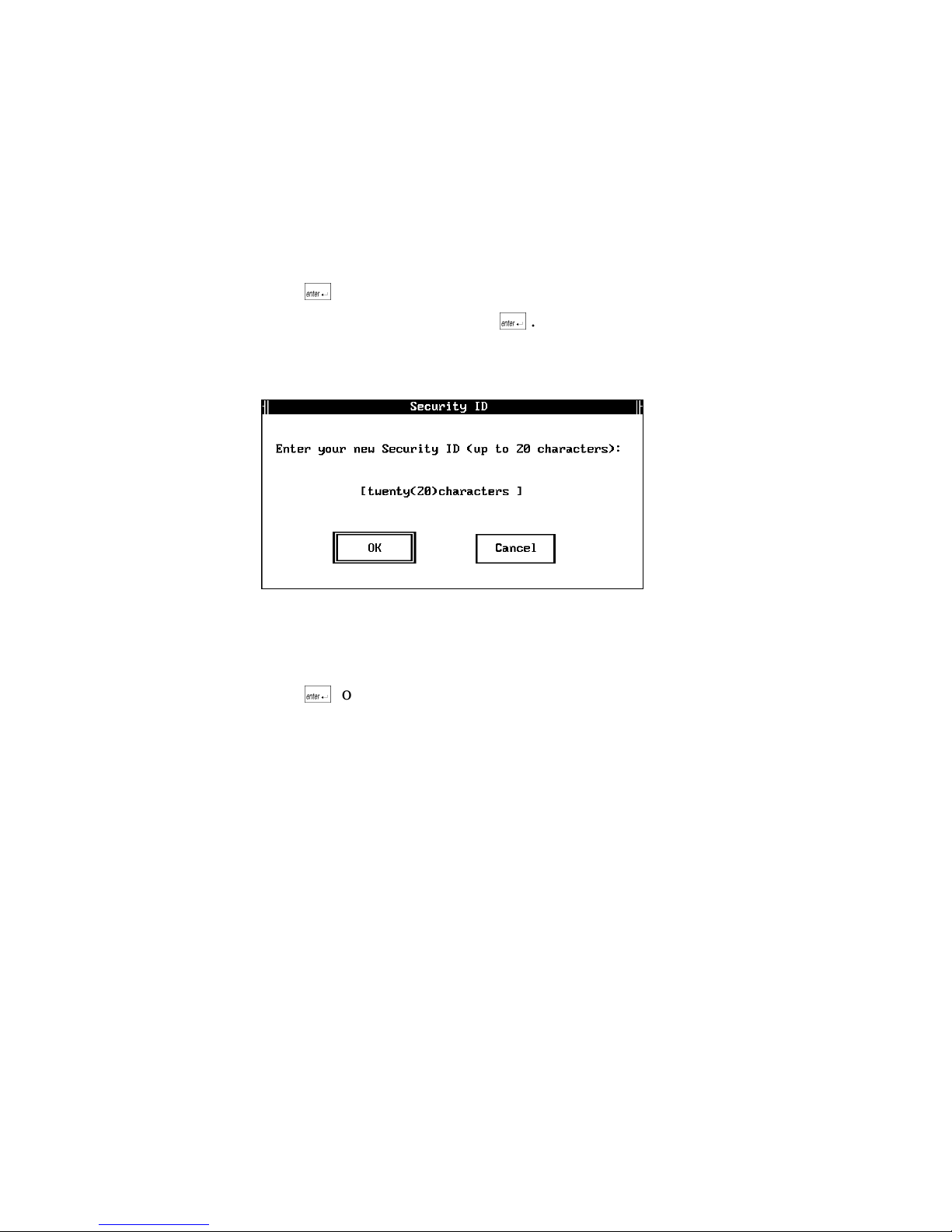
JANUS 2.4 GHz Installation Utility User’s Manual (4MB)
3. A warning message about the security ID option appears
Warning: AccessNet cards communicate only with other AccessNet
cards with the same Security ID. Be sure to set the Security
ID on all AccessNet cards in the same subnetwork to the same
value.
Press @ to choose the Continue button.
4. Enter the security ID and press @ . You can use up to 20 alphanumeric
characters. The security ID is case-sensitive.
Or, delete the security ID if you no longer want to use this feature.
5. A message informs you that your security ID has been updated.
Your AccessNet security ID has been updated.
Press @ to continue.
B-8
Page 97

Helpful Information
6. A message informs you that the operation was successful. The message box
also informs you of the JANUS device node address.
If you are not within range of an access point with the security ID set, you
can ignore the message that the JANUS device could not find a Master to
synchronize with.
B
However, if you are within range of an access point and the security ID is
correct, the message box informs you that the JANUS device is
synchronized to the access point and provides the node address of the
access point. For example:
Synchronized to 0020a63051df
7. Press A M (tab) to choose the Done button and press @ .
8. Press A M (tab) to select the Exit button and press @ .
9. On the host PC, press Alt-F4 to exit Interlnk. The utility deletes the files it
copied to drive C.
If you installed terminal emulation software on the JANUS device, it will try to
start a session with the host.
B-9
Page 98

JANUS 2.4 GHz Installation Utility User’s Manual (4MB)
Customizing the J24TE.INI File
For Intermec terminal emulation installations, the J24TE.INI file is copied from
the TE Applications disk to a subdirectory on your host PC. You may want to
customize the J24TE.INI file to permanently change your JANUS operating
environment. You can customize the J24TE.INI file to enable or disable
supported symbologies or to change other operating parameters such as beep
volume, display, viewport size and movement.
To customize the J24TE.INI file
1. Shell out to DOS during the installation process.
2. Type the following command from a DOS prompt on the host PC to start
Intersvr on the host.
a:intersvr
3. After Intersvr is running, remove the Installation Utility disk from drive A.
Note: Drive A must be empty or this process will not work.
4. Reboot the JANUS device by pressing > < A . When the JANUS
device boots, the Microsoft Interlnk Server Version Intermec menu appears
along with the server/client drive mapping screen.
Note: If you do not reboot the JANUS device while Intersvr is running on the host
PC, Interlnk will not load on the JANUS device and you will not be able to access
the drives on the host PC.
5. At the JANUS DOS prompt, type ( " and press @ to start the
configuration application (IC.EXE).
6. Select the LOAD option from the File menu.
7. Select the IM_FLASH\ directory and press @ .
8. Select the DRIVEC\ directory and press @ .
9. Select J24TE.INI and press @ .
10. Use IC.EXE to make your configuration changes. See your JANUS user’s
manual for more information on IC.EXE.
B-10
Page 99

11. Select SAVE from the File menu and press @ .
Note:
You can omit steps 8-11 if you can type X:\IM_FLASH\DRIVEC\J24TE.INI at
the NAME prompt and save the file. Where X is the drive letter on the host PC that
you are mapping to.
12. Select EXIT from the File menu.
13. Select No when you are prompted to update the online configuration on the
JANUS device.
14. Reinsert the Installation Utility disk in drive A on the host PC.
15. Press Alt-F4 on the host PC to exit Intersvr.
16. Type $ 7 ( 3 at the DOS prompt on the JANUS device and press @ .
You can now continue with the installation.
Creating a JANUS.INI File
Helpful Information
B
For Novell TNVTxxx and NetWare Client for DOS installations, you may want
to create a JANUS.INI file to permanently change your JANUS operating
environment. You can use a JANUS.INI file to enable or disable supported
symbologies or to change other operating parameters such as beep volume,
display, viewport size and movement.
To create a JANUS.INI file
1. Shell out to DOS during the installation process.
2. On the host PC , edit the \IM_FLASH\DRIVEC\AUTOEXEC.BAT file to
change:
d:\ic /l e:\janus.ini
to
d:\ic /l c:\janus.ini
3. Save the changed AUTOEXEC.BAT file.
4. At the DOS prompt on the host PC, type this command to start Intersvr.
a:intersvr
5. After Intersvr is running, remove the Installation Utility disk from drive A.
Note: Drive A must be empty or this process will not work.
B-11
Page 100

JANUS 2.4 GHz Installation Utility User’s Manual (4MB)
6. Reboot the JANUS device by pressing > < A . When the JANUS
device boots, the Microsoft Interlnk Server Version Intermec menu is
displayed along with the server/client drive mapping screen.
Note: If you do not reboot the JANUS device while Intersvr is running on the host
PC, Interlnk will not load on the JANUS device and you will not be able to access
the drives on the host PC.
7. At the JANUS DOS prompt, type ( " and press @ to start the
configuration application (IC.EXE).
8. Use IC.EXE to make your configuration changes. See your JANUS user’s
manual for more information on IC.EXE.
9. Select the SAVE AS option from the File menu. Type the drive letter on the
host PC that you are mapping to (refer to the server/client drive mapping
screen) and O ( - ( at the NAME prompt and press @ .
10. Select the IM_FLASH\ directory and press @ .
11. Select the DRIVEC\ directory and press @ .
12. Save the configuration you created as JANUS.INI and press @ . You are
saving the .INI file you created using the configuration application to the
drive on the host PC where the JANUS drive C image will be built. This file
is written to the JANUS flash memory and becomes a permanent part of
your configuration.
Note: You can omit steps 9-12 if you type X:\IM_FLASH\DRIVEC\JANUS.INI at the
NAME prompt and save the file. Where X is the drive letter on the host PC that
you are mapping to.
13. Select EXIT from the File menu.
14. Select No when you are prompted to update the online configuration on the
JANUS device.
15. Reinsert the Installation Utility disk in drive A on the host PC.
16. Press Alt-F4 on the host PC to exit Intersvr.
17. Type $ 7 ( 3 at the DOS prompt on the JANUS device and press @ .
You can now continue with the installation.
B-12
 Loading...