

Page 1
Installation & Operation, IPL Version
P/N 1-960490-02
Edition 3
August 2001
EasyCoder F4
Bar Code Label Printer
Page 2

Preface
Contents
Preface
Tab le o f Contents.................................................................................1
Copyright Information........................................................................3
Trademarks ..........................................................................................3
FCC Notice (U.S.A.)...........................................................................4
DOC Notice (Canada).........................................................................4
GS Notice (Germany).........................................................................4
EU Standard EN 55022 (The European Union)...............................4
Declaration of Conformity (CE)........................................................5
1. Introduction
Safety Precautions...............................................................................7
Product Labeling.................................................................................7
2. In s ta l l a t i o n
Front View...........................................................................................9
Rear View ..........................................................................................10
Media Compartment.........................................................................1 1
Print Mechanism...............................................................................14
Connections .......................................................................................15
• Power.............................................................................................15
• Computer.......................................................................................15
Controls and Indicators .....................................................................16
• Control Lamps..............................................................................16
• Display...........................................................................................1 6
• Keyboard.......................................................................................1 7
• Beeper ...........................................................................................17
3. Starting Up
4. Media Load
T ear-Off (Straight-through) with Quick-Load.................................23
Peel-Off (Self-strip)...........................................................................25
External Supply (fanfold)..................................................................29
5. Thermal Transfer Printing
6. Setting Up the Printer
Default Setup .....................................................................................34
Setup Parameters:..............................................................................35
• Serial Communication:................................................................35
EasyCode r F4
- Baud Rate ...................................................................................35
Installation & Operation
- Data Bits......................................................................................35
IPL Ve rsion
- Parity...........................................................................................35
Edition 3, August 2001
Part No. 1-960490-02
Description...........................................................................................6
Unpacking............................................................................................8
Switching On.....................................................................................18
T ear -Off (Straight-through) ..............................................................19
Ribbon Load ......................................................................................30
Description.........................................................................................34
Intermec EasyCoder F4 – Installation & Operation IPL Version, Ed. 3 1
Page 3

Preface
Contents, cont.
6. Setting Up the Printer, cont.
- Protocol.......................................................................................36
• T est/Service: .................................................................................38
- T estprint......................................................................................38
- Data Dump .................................................................................39
- Memory Reset............................................................................39
- Label Rest Dots..........................................................................39
- Form Adj Dots X........................................................................39
- Form Adj Dots Y........................................................................39
• Media: .......................................................................................... 40
- Media T ype................................................................................ 40
- Paper T ype................................................................................. 40
- Label Length ............................................................................. 40
- Sensitivity .................................................................................. 40
- Darkness .....................................................................................4 1
7 . Setup Mode
Navigating in Setup Mode................................................................42
Setup Mode Overviews.....................................................................43
8. Options
DTP Model ........................................................................................47
Side Doors and Megatop...................................................................47
Integral Liner T akeup U nit...............................................................47
Media Supply Hub.............................................................................47
3-inch Adapter...................................................................................47
Quick-Load Guides...........................................................................48
Label Taken Sensor...........................................................................48
Interface Boards ................................................................................48
9. T roubleshooting
10. Maintenance
External Cleaning..............................................................................53
Cleaning the Media Guides..............................................................54
Printhead Replacement.....................................................................55
11. Adjustments
Label Stop Sensor Position...............................................................59
Printhead Pressure............................................................................ 60
Ribbon Break Shaft Adjustment ......................................................61
Entering the Setup Mode..................................................................42
Introduction....................................................................................... 46
Troubl eshooting List..........................................................................49
Printhead Cleaning............................................................................50
Narrow Media Adjustment...............................................................58
- Stop Bits......................................................................................35
Intermec EasyCoder F4 – Installation & Operation IPL Version, Ed. 32
Page 4

Contents, cont.
Preface
Appendix 1
Appendix 2
• Direct Thermal Media................................................................ 64
• Thermal Transfer Media............................................................. 64
• Media Roll Size ............................................................................65
• Media.............................................................................................66
- Non-Adhesive Strip....................................................................66
- Self-A dhesiv e S trip ....................................................................67
- Self-A dhesiv e Labels.................................................................68
- Tickets with Gap........................................................................69
- Tickets with Black Mark............................................................70
• Transfer Ribbons ..........................................................................71
• Setting the Media Sensitivity Number........................................72
Appendix 3
• RS-232 Interface...........................................................................75
• IEEE 1284 Parallel Interface Board (option).............................76
• EasyLAN 100i Interface Board (option)....................................77
Appendix 4
Information in this manual is subject to change without prior notice and does not represent a commitment
on the part of Intermec Printer AB.
© Copyright Intermec Printer AB, 2001 . All rig hts reserved. Published in Sweden.
EasyCoder, EasyLAN, Finge rprint, and LabelShop are registered trademarks of Intermec Technologies
Corp. T he word Interm ec, the Inter mec logo, Prin tSet, a nd Durather m are tradem arks of Inter mec
Technologies Corp.
Kimdura is a registered trademark of Kimberly Clark.
Centronics is a registered trademark of Genicom Corporation
Microsoft is a registered trademark of Microsoft Corporation.
To rx is a reg ister ed trademark of Camcar Division of T extron Inc.
T rueDoc is a registered trademark of Bitstream, Inc.
T rueType is a trademark of Apple Computer Inc.
Unicode is a trademark of Unicode Inc.
Valeron is a re g istered tr ademark of Van Leer Worldwide
Windows is a trademark of Microsoft Corporation.
T echnical Data...................................................................................62
Media Specifi cations........................................................................ 64
Interfaces............................................................................................75
Supported IPL- 3 commands.............................................................78
Intermec EasyCoder F4 – Installation & Operation IPL Version, Ed. 3 3
Page 5

Preface
FCC Notice (United States of America)
WARNING
This equ ipment generates, uses, and ca n rad iate ra dio f requency energy a nd i f not insta l led a nd used i n
accordance with the i nstr uctions manual, may cause inter ference to radio communications. It has been
tested and found to comply with the limits for a Class A computing device pursuant to Subpart J of Part
15 of FCC Rules, which are designed to provide reasonable protection against such interference when
operated i n a commercial environm ent. Operation of this e quipment in a residential ar ea is likely to
cause interference in which case the user at his own expense will be required to ta ke whatever measures
may be required to correct the interference.
DOC Notice (Canada)
Canadian Dept. of Communication
REGULATIONS COMPLIANCE (DOC-A)
This digital apparatus does not exceed the class A limits for radio noise emissions from a digital apparatus
as set out in the radio interference regulations of the Canadian Department of Communication.
Ministère des Communications du Canada
CONFORMITE DE REGLEMENTS (DOC-A)
Le présen t appareil numériq ue n ’émet pas de bruits radio-électriques dépassant les limites applicables aux
appareils numériques de classe A prescrites dans le règlemen t sur brouillage radioélectrique édicté par le
Ministère des Communications du Canada.
GS Notice (Germany)
ALLGEMEINE VORSCHRIFT
Reparaturen oder sonstige Eingriffe, die sich nicht auf normale Bedienung der Maschine beziehen, dürfen
ausschließlich nur von einem ausgeb ildeten, zuständigen F achmann vorgenommen werden.
EU Standard EN 55022 (The European Union)
WARNING
This is a Class A I TE pro duct. In a domestic environment t his product may cause rad io inter ference in
which case the user may be required to take adequate measures.
Intermec EasyCoder F4 – Installation & Operation IPL Version, Ed. 34
Page 6

Declaration of Conformity
We,
Intermec Printer AB
Idrottsvägen 10
Box 123
S-431 22 Mölndal
Sweden
declare under our sole responsibility1 that the product
EasyCoder F4
to which this declaration relates
is in conformity with the following standards
EMC:
EN 50 081-1:1992
EN 55 022:1994
EN 61 000-3-2:1995, class A
EN 50 082-2:1995
EN 61 000-4-2:1995
EN 61 000-4-3:1996
ENV 50 204:1995
EN 61 000-4-4:1995
EN 61 000-4-6:1996
Electrical Safety:
EN 60 950
following the provisions of Directives
89/336/EEC and 73/23/EEC
Mölndal 1999-09-01
Preface
...................................................................
Mats Gunnarsson
President
1
/. Intermec assumes no responsibility regarding the CE Directive if the
printer is handled, modifi ed, or installed in other manners than those described in
Intermec’s manuals.
Intermec EasyCoder F4 – Installation & Operation IPL Version, Ed. 3 5
Page 7

Chapter 1
Introduction
Description
The EasyCoder F4 is a sturdy medium-duty direct thermal/thermal
tr ans fer pr inte r with a p rin the ad res oluti on of 8 dot s per m m
(20 3.2 dots p er inch ) and a ma xim um pri nt widt h of 104 mm
(4.095 inches).
The Easy Coder F4 is delivered with the I ntermec P rogramm ing
Language (IPL- 3) installed. There is also a version of the EasyCoder
F4 tha t uses the I nterme c Finger print P rogra mmin g Langua ge.
Mechanically, the IPL version is iden tical to the Intermec Fingerprint
version, but a f ew options are not supported by IPL-3, f or ex ample:
• Optional double serial and industrial interface boards
• Electronic keys
• Memory cards (except for fi rmware upgrading)
• EasySet Bar Code Wand
• Real Time Clock Circuit
In most respects, the EasyCoder F4 IPL version is compatible with
other IPL pri nters f rom Inter me c. Please refer to Appendix 4 for a
list of supported IPL- 3 commands.
Intermec EasyCoder F4 – Installation & Operation IPL Version, Ed. 36
Page 8

Chapter 1 Introduction
Safety
Precautions
Product Labeling
Intermec a ssumes no responsibility regarding the CE Dire ctive if
the printer is handled, modifi ed, or installed in a ny way other than
described in Intermec’s manuals.
Caution
• Read this manual carefully before connecting the printer.
• Moving parts are exposed when the side door is open, so ensure
that the door is closed before you operate the printer.
• Do not open the front/left-hand cover. Dangerous v o ltage!
• Do not remove the bottom plate. Dangerous vol tage!
• Do not put your fi ngers inside the print mechanism when
the powe r i s o n .
• Place the printer on an even surface which can support its wei ght
of approximately 7 kg ( 1 5 .5 lb ) pl us supp lies.
• Do not spray the printer with water. If you are using a hose to clean
the premises in an industrial environment, remove the printer or
protect it carefully from spray and moisture.
• Carefully read the war ning text on the envelope before using
a cleaning card.
The machine label is attached to the printer’s rear plate and contains
information on type, model, and serial number a s well as AC input
voltage range. I t also contains various signs of approval.
Intermec EasyCoder F4 – Installation & Operation IPL Version, Ed. 3 7
Page 9

Chapter 2
Installation
Unpacking
Before you inst all the p rinter, exam ine the p ackage for possible
damage or missing parts:
• Open the box and lift the printer out.
• Check that the printer has not been visibly damaged during
transpor tat ion. Keep the packing mat erials i n case you need to
move or reship the printer.
• Check the label on the printer’s rear plate, which giv es the voltage,
the part number, and the serial number.
• Check that any options you ordered are included.
• Check that all accessories are included. As standard, the
box contains:
- Intermec EasyCoder F4 printer
- Two sets of Quick-Load guides (wide and narrow)
- Power cord (at least one depending on model)
- Quality check card
- Cleaning card
- Short strip of labels
- Adapter for 3-inch media roll core (only in models fi tted
with a rotating media supply hub)
- Starter pack of thermal transfer ribbon (thermal transfer
models only)
- User’s Guide (multilingual)
- Installation & Operation manual
- Supporting software and product information on CD.
• Check that the power cord is appropriate for the local standard. The
printer works within 100 to 240 VAC, 50 to 60Hz.
1
1
1
/. T ype and quantity may vary,
or labels/ribbon may be omitted completely, dependi ng on
area of distribution.
European-type US/Canadian-type GB-type
230V mains plug 115V mains plug 230V mains plug
If the pr inter has b een da maged in a ny way during tra nspor tat ion,
complain to the carrier immediately.
If t he del iver y is inc orr ect or a ny par ts a re mi ssing , repo rt it
immediate ly to the di s trib u t o r.
Intermec EasyCoder F4 – Installation & Operation IPL Version, Ed. 38
Page 10
Chapter 2 Installation
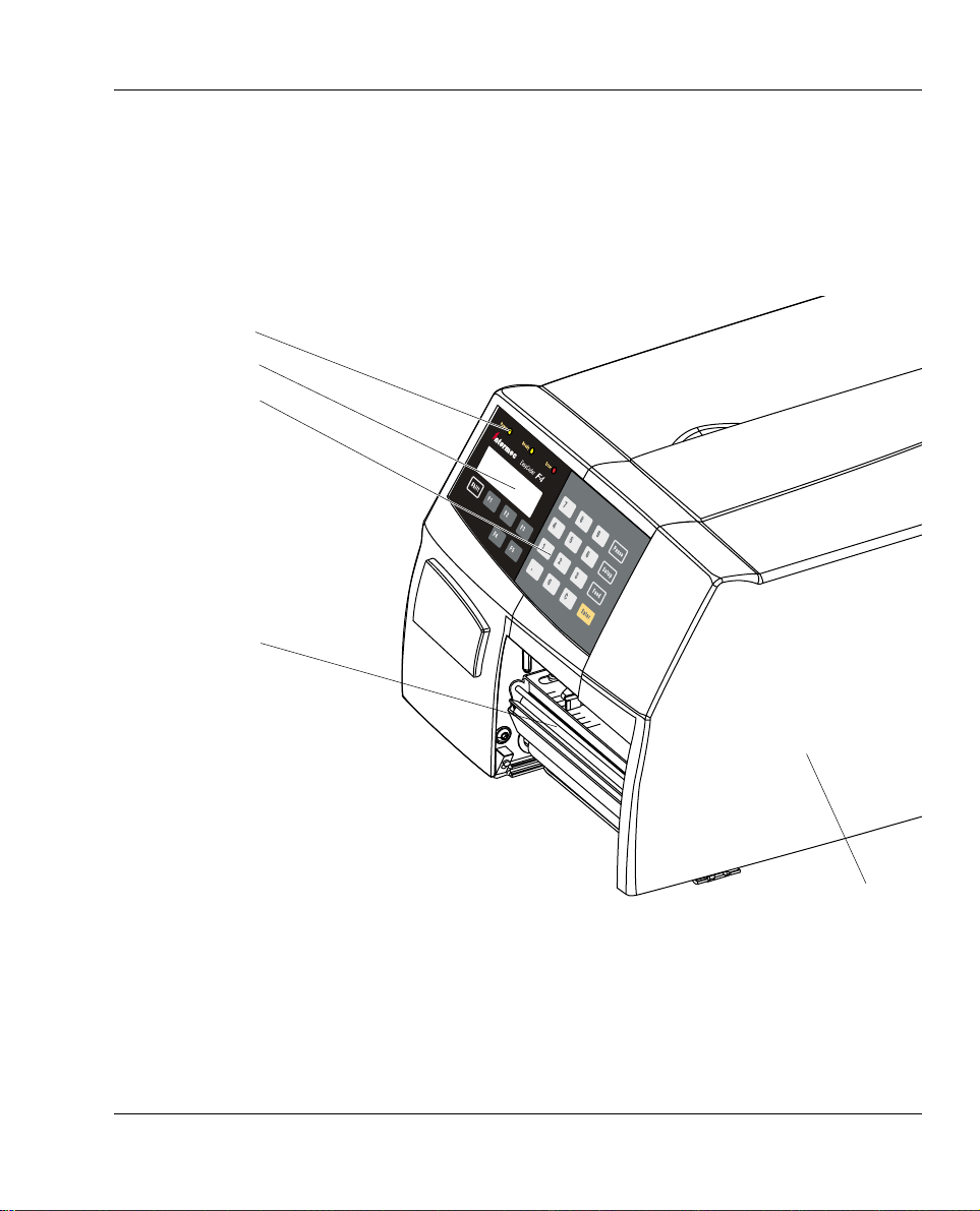
Front View
Control Lamps
Display Window
Keyboard
Print Mechanism
At the front of the printer are the display window, the control lamps,
and the keyboard. These featu res a l low the operator to cont rol and
set up the printer manually .
The p rinte d labels, t ickets, or t ags are pr esente d at the fr ont of
the print mechanism.
Side Door
Intermec EasyCoder F4 – Installation & Operation IPL Version, Ed. 3 9
Page 11
Chapter 2 Installation
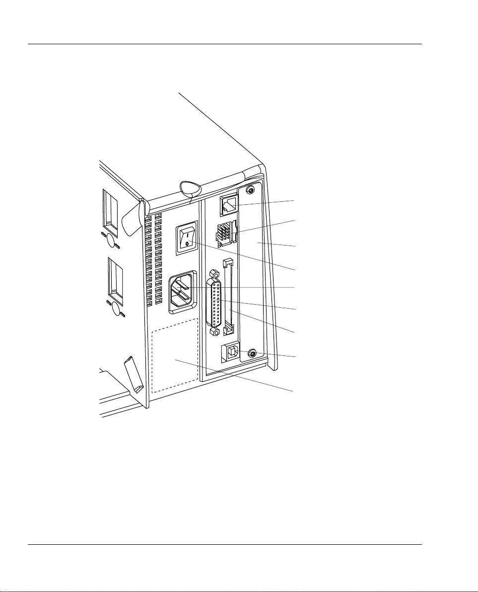
Rear View
The r ear plat e conta ins th e On/ Off sw itch, the AC power c ord
receptacle, and various interface connectors and slots.
(not used)
(not used)
Provision for one Interface Board
On/Off Switch
AC Power Cord Receptacle
RS-232 Serial Interface Socket
Memory Card Slot (for fi rmware upgrade)
(not used)
Machine Label
Intermec EasyCoder F4 – Installation & Operation IPL Version, Ed. 310
Page 12
Chapter 2 Installation
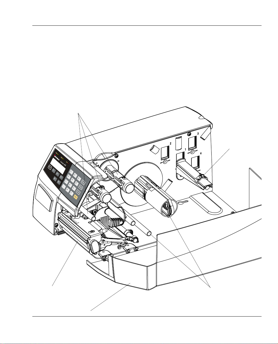
Media Compartment
Thermal Transf er Mechanism
(optional)
The media compa rt ment is either covered by a long side door that
completely encloses the print mechanism and media compartment,
an 8-inch Megatop for extra large media rolls, or a short side door that
only covers the print mechanism and giv es easy access to the media
stock. The door is held by a magnetic lock. It can be opened 180° so
to provide full access to the media compartment.
The media supply can be from a supply post, or from an exter nal
supply of fan folds beh ind the pri nter. There is a lso an optiona l
rotating media supply hub, see Chapter 8 “Options.”
Media Supply
Roll Post
with Edge Guide
Print Mechanism
Long Side Door
Optional Integral Liner
Takeup with Guide Shaft
Intermec EasyCoder F4 – Installation & Operation IPL Version, Ed. 3 11
Page 13
Chapter 2 Installation
Media Compartment, cont.
Since the EasyCoder F4 has a modular design, it uses a media supply
roll post that can be fi tted in three different positions inside the
media compartment. The position depends on the type of side door
(long, short, or Megatop) and whether or not the printer is fi tted with
an integral liner takeup. Alternatively, an external media supply
(for example a box of fan folded tickets) behind the printer ca n be
used. A rotating med ia supply hub is also available as an option,
see Chapter 8, “Option s.”
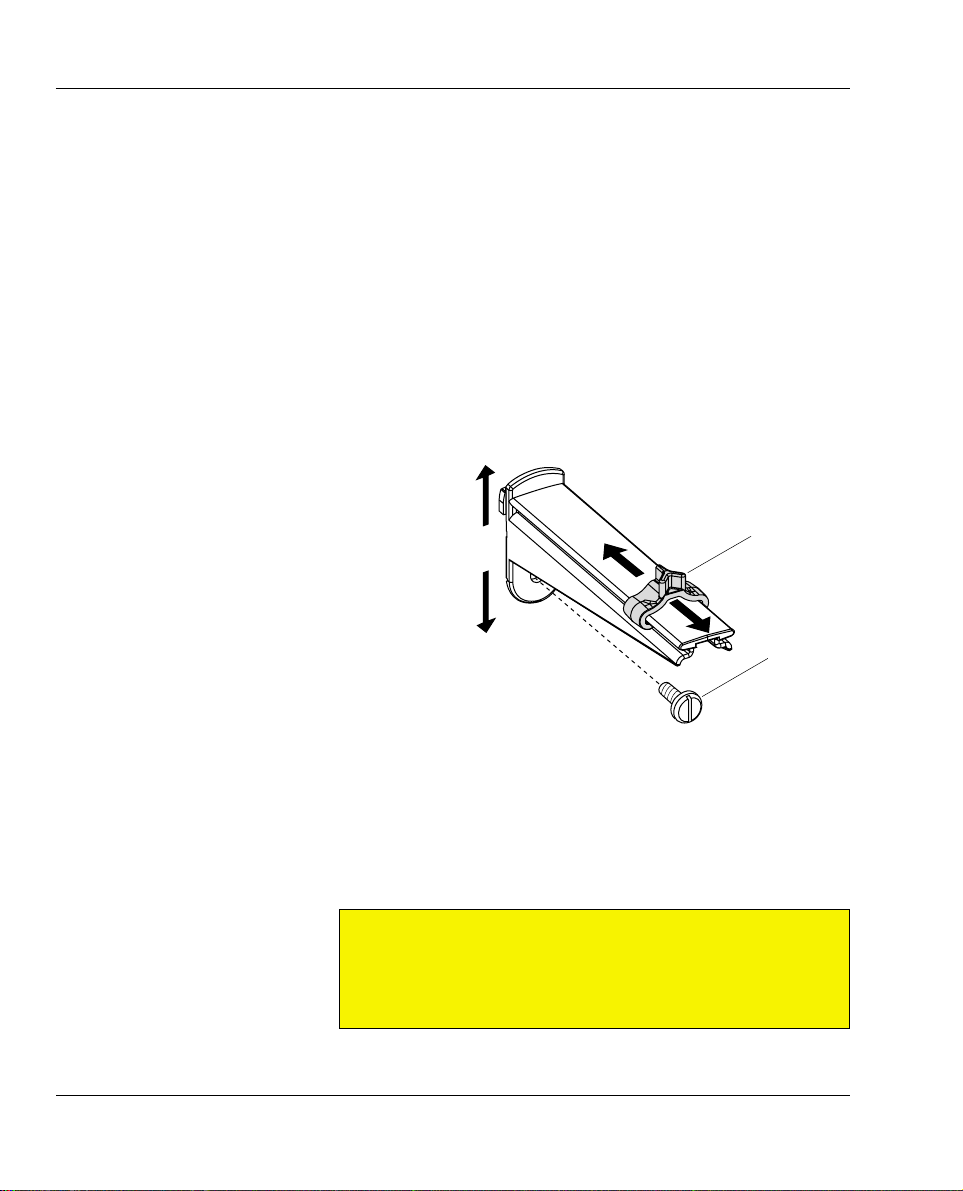
Media Supply Roll Post
The media supply roll post fi ts b oth 38-40 m m (1.5 inches) an d
76 mm (3.0-inches) cores, since it can be moved vertically in the
slot i n the ce nter s ectio n. The b otto m posit ion is int ende d for
small cores and t he top position for large cores only. The post is
locked by a straight-slot screw and has a moveable edge guide to
fi t various media widths.
76 mm
(3 inches)
Edge Guide
CORE
38 - 40 mm
(1.5 inches)
Screw
T o mo v e the post to a different slot; remov e the screw, twist the post
a quarter of a turn, and pull it out.
To fi t the post; rotate it a quarter of a turn, insert it into the approp-
riate slot in the c enter section (see next page), and twist back so
the l ips enga ge the cut outs in t he sides of t he slot. M ove it up
(large core) or down (small core) as far as it goes and secure it
with the screw .
Caution!
Make sure to adjust the posit ion o f the p ost a ccording to the size
of the media roll core. W he n th e pos t is fi tted in the top position ,
the head of the screw will interfere with small (38 mm/1.5 inches)
cores, causing media misalignment.
Intermec EasyCoder F4 – Installation & Operation IPL Version, Ed. 312
Page 14
Chapter 2 Installation
Media Compartment, cont.
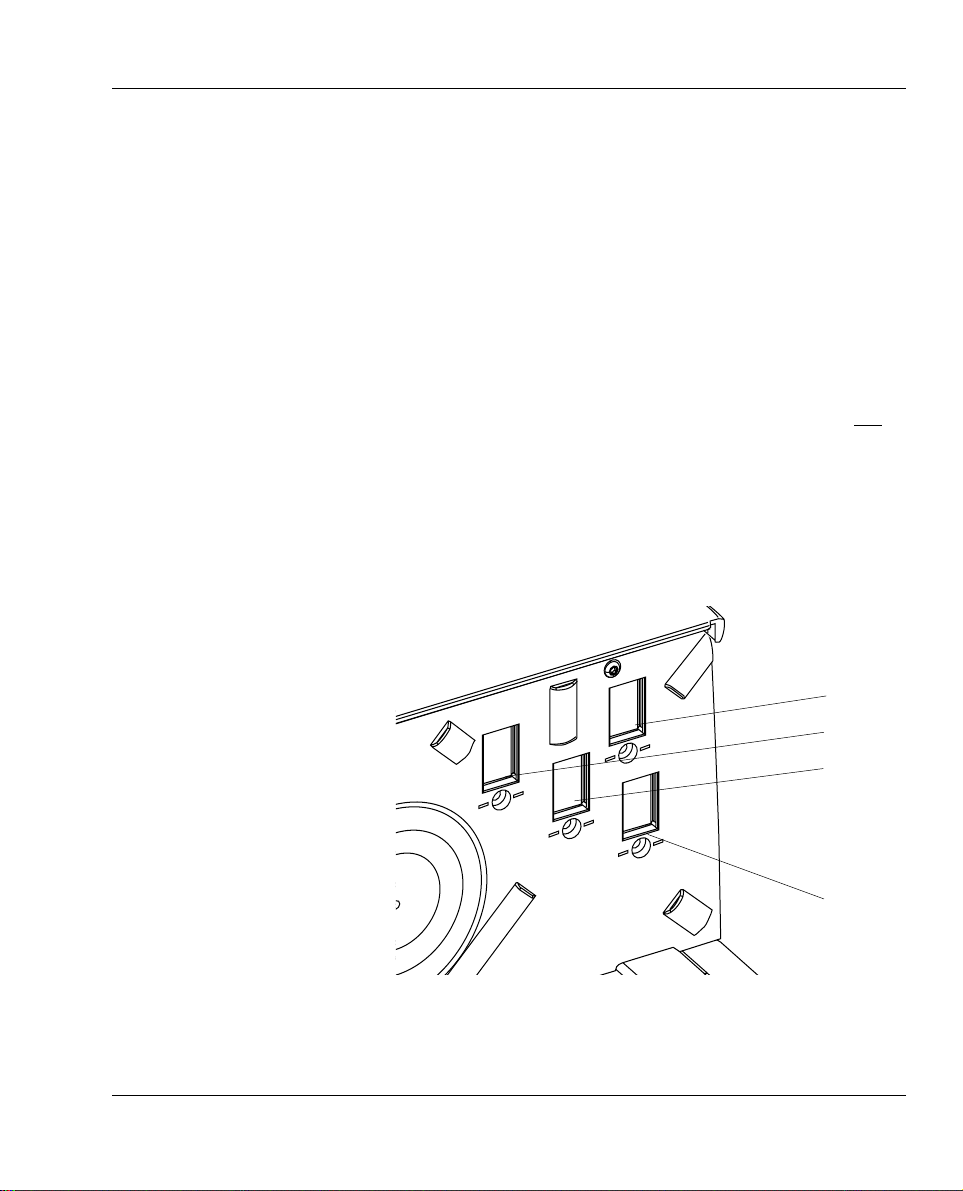
Media Supply Positions
There are four sets of slots and threaded holes in the printer’s center
section for th e media supply roll post or rot ating hub (optional) .
The se slots a llow th e large st possib le roll si ze to fit, given t he
limitati ons o f any liner take up uni t and/or the fu ll enc los ure pro vide d
by the long side door or Megatop. The positions are indicate d by
numbers engraved in the center section.
• Position 1 is used when the media compartment is fully enclosed
by a long si de door, regardless of the existence of any integral liner
takeup unit. Maximum roll size is 152 mm (6 inches).
• Position 2 is used when the printer has a short side door that only
encloses the print mechanism, but does not hav e an integral liner
takeup unit. Maximum roll size is 213 mm (8.38 inches).
• Position 3 is used when the printer has a short side door a nd an
integral liner takeup unit. This position is also used with the
optional 8-inch Megatop, see Chapter 8, “Optio ns.” Maximum
roll size is 21 3 mm (8.38 inches).
• Position 4 is reserved for possib le future devel opment.
The printer can also use an external media supply located behind the
printer, unless it has an optional 8-inch Megatop .
3
2
1
4
Pos. 3
Pos. 2
Pos. 1
(Pos. 4)
Intermec EasyCoder F4 – Installation & Operation IPL Version, Ed. 3 13
Page 15
Chapter 2 Installation
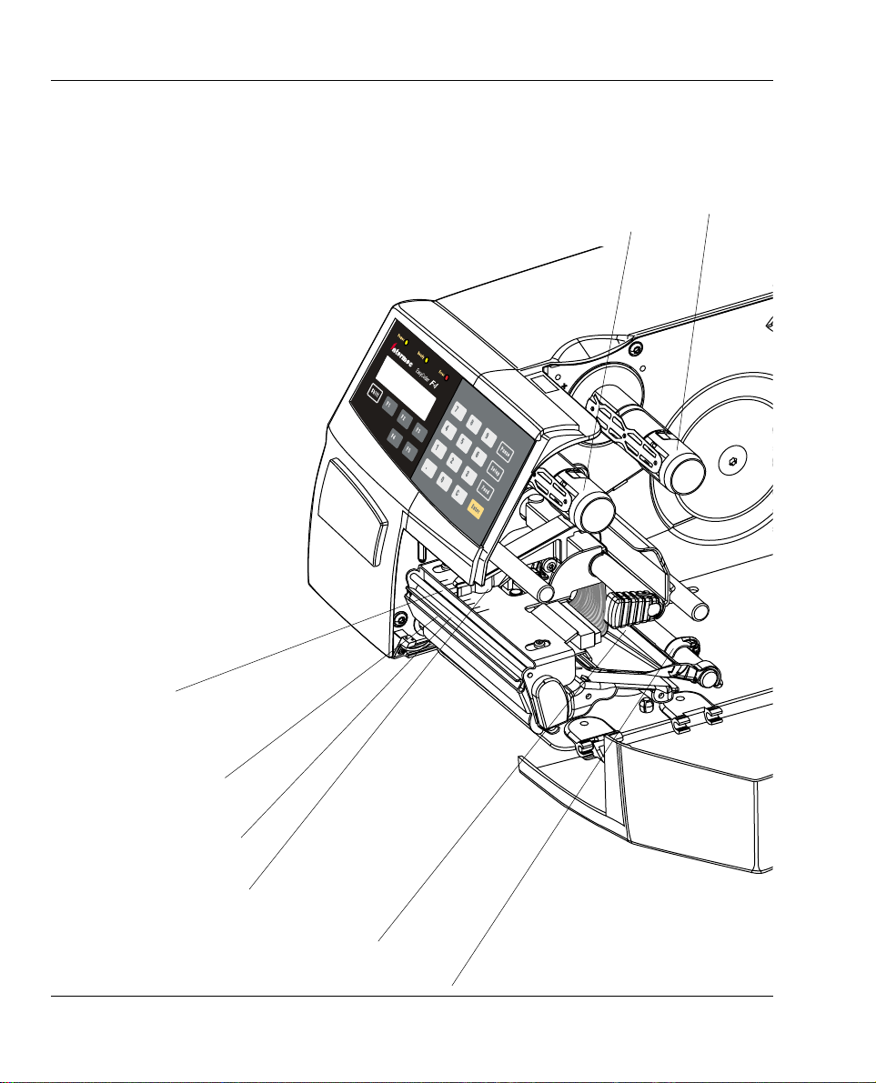
Print Mechanism
The print me chanism features a h igh-performa nce 8 dots-per-mm
(203.2 dots-per-inch) thermal printhead with quick-mount fi ttings
to facilitate replacemen t. The thermal transfer ribbon mechanism is
omitted in dedicated direct thermal printing models.
Ribbon Supply Hub
Ribbon Rewind Hub
Thermal Printhead
Tear Bar
Platen Roller
Pressure Arm
Printhead Lift Lever
Edge Guide
Intermec EasyCoder F4 – Installation & Operation IPL Version, Ed. 314
Page 16

Connections
Chapter 2 Installation
Power
Computer
1 Place the printer on a lev el surface near an AC outlet. Y ou should
be able to easily access the printer to load media, to load ribbon,
and to remove the printout
2 Check that the printer is switched off.
3 Connect the power cord between the receptacle on the rear plate
and an electrical outlet (>90 to <264 VAC).
The EasyCoder F4 is fi tted with one 25pin D-style submi niature
(DB25) socket for the RS-232 serial interface port (see Appendix
3). The p rinter is a lso prepared for one opt ional inter face board
(auto-sensing).
• RS-232 Serial Interface
Use the serial interface when you need a two-w ay communication
between printer and host computer. Before you can use the
serial interface, you may need to set up the communication
parameters, such as baud rate, parity, etc. as described in Chapter
6, “Setting Up the Printer.”
• Parallel Interf ac e Board
Optional. Refer to Appendix 3 a nd the separ ate documentat ion
delivered with the board for connection and setup instructions.
• EasyLAN 100i Interface Board
Optional. Refer to Appendix 3 and t he separat e documentat ion
delivered with the board for connection and setup instructions.
Switch of f both t he PC and t he prin ter before c onnect ing them
together.
Intermec EasyCoder F4 – Installation & Operation IPL Version, Ed. 3 15
Page 17
Chapter 2 Installation
Controls and
Indicators
Control Lamps
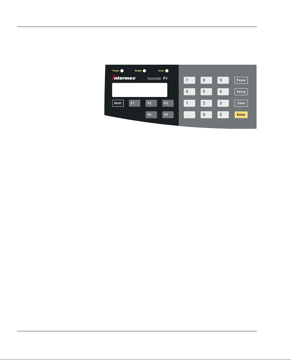
The EasyCoder F4 has several ways of communicating directly with
its operator: thre e control lamps, a display window, a membraneswitc h k eyboard wi th 2 2 k e ys, a bi g “Feed” button on the printer’s
front, and a beeper. Only some of the key s are used with IPL.
The control lamps a re colored LEDs (Light Emitt ing Diodes) and
indicate the following conditions:
• Power (green):
On Power on
Off Power off
• Ready (green):
On Media fault detected
Flashing Printer offl ine
Off Printer online
• Error (red):
On System fault detected
Flashing Printer overtemperature
Off OK
Display
The d isplay window con tain s an LCD ( Liquid Cryst al Displ ay)
with background illumination and two lines of text, each with
16 characte rs. It guides t he operator t hrough upg rading, st art up,
and se tup.
Intermec EasyCoder F4 – Installation & Operation IPL Version, Ed. 316
Page 18

Controls and Indicators, cont.
Chapter 2 Installation
Keyboard
Beeper
The keyboard is of membra ne-switch type and has 22 keys. The
keyboard is supplemented by a large “Feed” button on the printer’s
front. Only four of these keys plus the “Feed” button are work ing
with I PL (except in the Set up Mode where t he keyboard work s
differently, see Chapter 7, “Setup Mode”).
Condition <Feed> <C> <Pause> <Setup>
Idle Feed/Reload – Toggle offl ine/online Enter Setup Mode
Printing – – Hold printing –
Paused Feed/Reload Cancel print job Resume printing Enter Setup Mode
“Feed” means advanci ng the media one form, whereas “Reload”
means notifying the hardware when certain confi guration commands
have been entered.
The be ep e r n o ti fi es the operator that a key has been pressed.
Intermec EasyCoder F4 – Installation & Operation IPL Version, Ed. 3 17
Page 19

Chapter 3
Starting Up
Switching On
Before switching on the pri nter, make the necessa ry connect ions
and c he c k tha t the p rin the ad i s engag e d.
Switch on the power us ing the On/Off switch on the rear plate. The
“Power” control lamp on the front pa nel lights up when the power
is on. Wait for a few moments, while the printer loads the program
and runs some self-diagnostic tests.
Whi le the pri nter is init ialize d, the progre ss of the initia lizat ion
is indicated by an increasing number of colons on the lower line
in the display:
Initializing
:::
When the in itialization is completed, a label is fed out. Then t he
follow ing mess age appe ars, i ndica ting t hat the p rint er is rea dy
for operation:
IPL Ver 1.3
9600-8-N-1-X/X
The uppe r line ind icates the I PL version number and lower line
shows t he eithe r the pr esent s eria l commu nica tion set up or a n
error message:
- Paused
- Printhead Up
- Press Feed
- Paper Out
- Ribbon Out
- Printhead Hot
Intermec EasyCoder F4 – Installation & Operation IPL Version, Ed. 318
Page 20
Media Load
Chapter 4
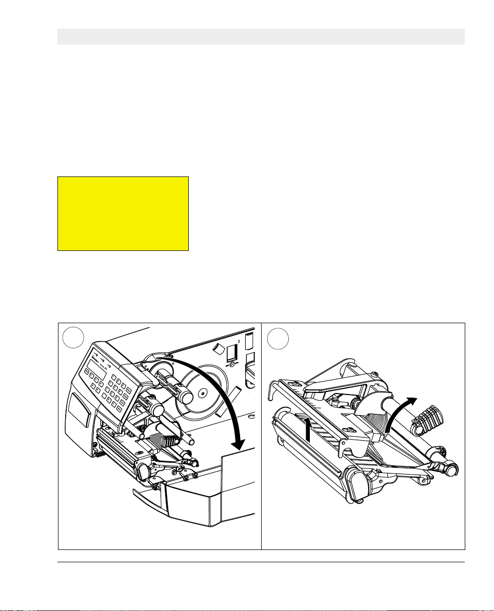
Tear-Off
(Straight-through)
Important!
Sa ve the l abe l ind ica ting t he
sensitivity num ber attached to
th e medi a roll . You will n eed
th is nu mber t o set t he me dia
sensitivity, see Appendix 2.
1
The EasyCoder F4 can print on labels, tickets, tags, and continuous
stock in various forms. Th is chapter describes the case when the
media is to be torn off manually against the pr i nter’s tear bar. This
method is also known as “straight-through printing”.
T ear-off can be used for:
• Non-adhesive continuous stock
• Self-adhesive continuous stock wi th liner
• Self-adhesive labels with liner
• Tickets with gaps, with or without perforations
• Tickets with black marks, with or without perforations
2
Turn the printhead lift lever clockwise to raise
Open the side door.
Intermec EasyCoder F4 – Installation & Operation IPL Version, Ed. 3 19
the printhead.
Page 21
Chapter 5 Ribbon Load
Tear-Off, cont.
43
3
2
1
4
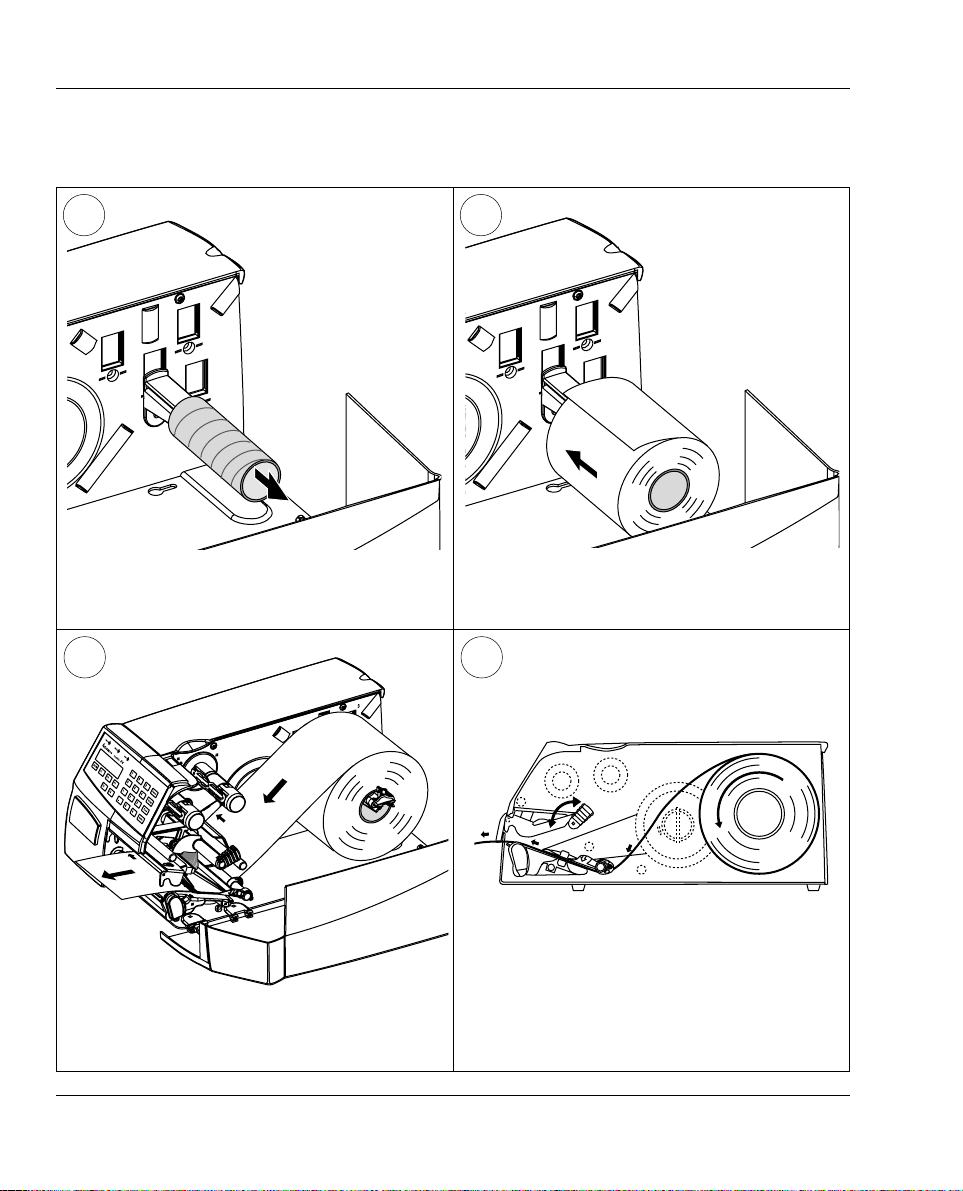
Remove any empty core from the media supply
roll post.
5
3
2
1
4
Fit a new roll of media on the supply post and
adjust the edge guide so the roll becomes fl ush
with the center section.
6
Route the media through the print mechanism.
Then push it inwards as far as it will go. This diagram shows the media path.
Intermec EasyCoder F4 – Installation & Operation IPL Version, Ed. 320
Page 22
Tear-Off, cont.
7 8
Chapter 4 Media Load
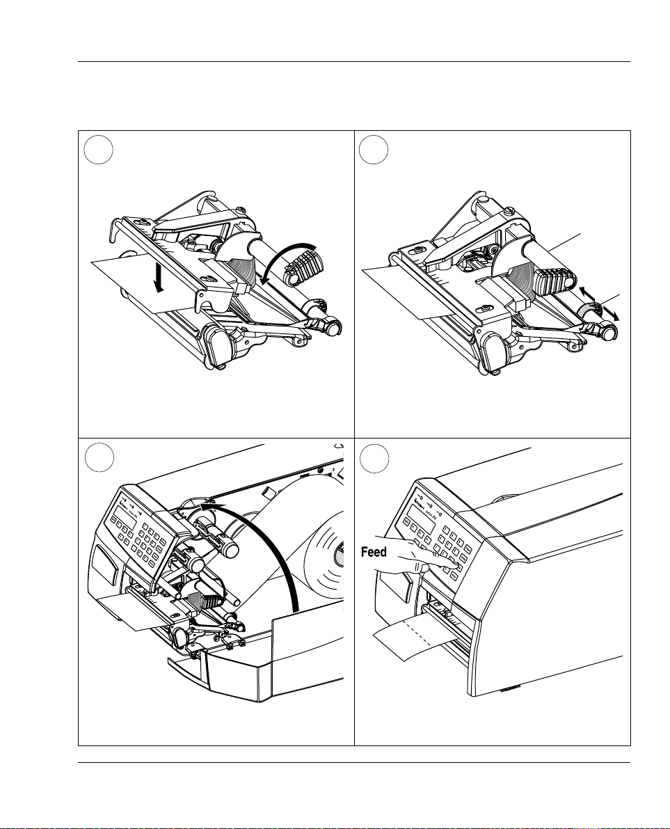
Turn the printhead lift lever counterclockwise
to engage the printhead.
9
Close the side door.
Intermec EasyCoder F4 – Installation & Operation IPL Version, Ed. 3 21
Adjust the position of the green edge guide so
the media is guided with a minimum of play.
10
Press the Feed key to advance the media and
adjust the media feed.
Page 23
Chapter 4 Media Load
Tear-Off, cont.
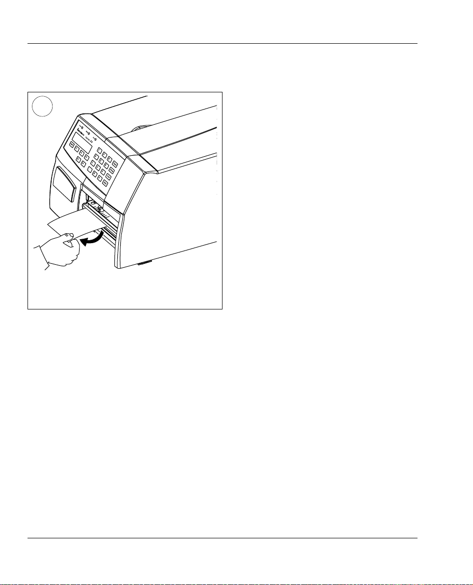
11
To tear off the media, grab the outer edge and
pull downwards.
Intermec EasyCoder F4 – Installation & Operation IPL Version, Ed. 322
Page 24
Chapter 4 Media Load
Tear-Off with Quick-Load
(Straight-through)
Important!
Sa ve the l abe l ind ica ting t he
sensitivity num ber attached to
th e medi a roll . You will n eed
th is nu mber t o set t he me dia
sensitivity, see Appendix 2.
1
In addition to the media load procedure for tear-off (s traight-through)
operation described e arlier in this chapter, the Ea syCoder F4 can
optionally be fi tted with a set of Quick-Load guides that makes media
load much easier and quicker , especially if the printer has a short side
door. See Chapter 8, “Options” for installation instructions.
The p rint er is nor mally de livered wit h two set s of Quick-Loa d
guides: wide and narrow . The wide type generally guides the media
better, but the media must be at least of 80 mm (3.15 inches) wide.
The nar row type a llows a media width as nar row as 40 mm (1.57
inches), but may be less suited for wide and thin media. Illustrations
in this chapter show the narrow type of guides.
Quick-Load cannot be combined with peel-off (self-strip) operation .
2
Fit a new roll of media on the supply post and
Remove any empty core from the media supply
roll post.
Intermec EasyCoder F4 – Installation & Operation IPL Version, Ed. 3 23
adjust the edge guide so the roll becomes fl ush
with the center section.
Page 25
Chapter 4 Media Load
Tear-Off with Quick-Load, cont.
3 4
Insert the media between the guides and feed
If necessary, adjust the outer Quick-Load
guide to fi t the width of the media.
it forward until the media reaches the platen
roller and cannot be inserted any further.
5
Keep pushing the media forward while
pressing the Feed key.
6
To tear off the media, grab the outer edge and
pull downwards.
Intermec EasyCoder F4 – Installation & Operation IPL Version, Ed. 324
Page 26

Chapter 4 Media Load
Peel-Off
(Self-strip)
Important!
Sa ve the l abe l ind ica ting t he
sensitivity num ber attached to
th e medi a roll . You will n eed
th is nu mber t o set t he me dia
sensitivity, see Appendix 2.
The EasyCoder F4 can print on labels, tickets, tags, and continuous
sto ck in va rio us form s. Th is cha pter d escr ibe s the ca se whe n
self-adhesive labels are separated from t he liner i mme diately af ter
printing. The liner is then wound up on an integral liner takeup hub.
This is also known as “Self-strip” operation.
Peel-off operation cannot be p erformed when Quick-Load guides
are fi tted.
Peel-off can only be used for:
• Self-adhesive labels with liner
An optional label ta ken sensor can hold the pri nting of next label
in a batch unti l the present label has been removed, see Ch apter
8, “Opti ons.”
1 2
Turn the printhead lift lever clockwise to raise
Open the side door.
Intermec EasyCoder F4 – Installation & Operation IPL Version, Ed. 3 25
the printhead.
Page 27

Chapter 4 Media Load
Peel-Off, cont.
3
Pull out the handle to collapse the takeup hub,
then remove any liner.
5
2
3
1
4
4
3
2
1
4
Remove any empty core from the media supply
roll post. Remove the edge guide if necessary.
6
Fit a new roll of labels on the supply post and
adjust the edge guide so the roll becomes fl ush
with the center section.
Intermec EasyCoder F4 – Installation & Operation IPL Version, Ed. 326
Remove labels from the fi rst 50 cm (20 inches)
of the liner. Route the liner through the print
mechanism and push it inwards.
Page 28

Peel-Off, cont.
Chapter 5 Ribbon Load
7
Route the liner around the tear bar and the
liner drive roller and back under the print
mechanism and guide shaft.
8
Insert the start of the liner under the lip of the
takeup hub, then rotate the hub counterclock-
wise a few turns to wind up some of the liner.
9 10
Turn the printhead lift lever counterclockwise
This diagram shows the media and liner paths.
Intermec EasyCoder F4 – Installation & Operation IPL Version, Ed. 3 27
to engage the printhead
Page 29

Chapter 5 Ribbon Load
Peel-Off, cont.
11
Adjust the position of the green edge guide so
the media is guided with a minimum of play.
13
12
Close the side door.
Press the Feed key to advance the media and
adjust the media feed.
Intermec EasyCoder F4 – Installation & Operation IPL Version, Ed. 328
Page 30

Chapter 4 Media Load
External Supply
1
The EasyCoder F4 can print on labels, tickets, tags, and continuous
stock in various forms. Th is chapter describes the case when the
media supply is placed behind the pr inter, usually in the form of
fan folded tickets or tags. External supply can be used with tear-off
(straight-through) printing–preferably with Quick -Load.
External supply can be used with both short and long side doors and
there is no need to remove the media supply roll post.
When using an external media supply , take care to protect the media
from dust, dirt, or other foreign particles, that can impair the printout
quality or cause unnecessary wear to the printhead.
Depending on brand and quality, all direct thermal media are more
or less sensitiv e to heat, direct sunlight, moisture, oil, plasticizers, fat,
and other substances. You should protect them accordingly.
This diagram shows the media path from an external supply. In case of the standard edge guide
(as opposed to Quick-Load guides), turn it to vertical position.
Intermec EasyCoder F4 – Installation & Operation IPL Version, Ed. 3 29
Page 31

Chapter 5
Thermal Transfer Printing
Ribbon Load
Important!
Sa ve the l abe l ind ica ting t he
sensitivity num ber attached to
th e medi a roll . You will n eed
th is nu mber to se t the m edi a
sensitivity, see Appendix 2.
1
The EasyCoder F4 can print on labels, tickets, tags, and continuous
stock using either direct ther mal pri nting on specia l heat-sensitive
paper or thermal transfer printing using a special ink -coated ribbon.
For ther mal tra nsfer print ing, the pr inter is fi tted with a transfer
rib b o n m e c h anism .
Therma l tra nsfer printi ng makes it possible to use a wide range of
receiving face materials. Make sure to select a type of ribbon that
matches the type of receiving face material (see Appendix 2, “Media
Specifi cat ion”) and to set up the pr inter accordingly (see Chapter
6. “Setting Up the Printer.”)
The Easy Coder F4 can use t ransfer ribbon rolls wound wit h the
ink-coated side facing either outward or inward. Illustrations in this
manual show the ink-coated side facing inward.
Most transfer ribbons do not smear at room temperature.
2
Open the side door.
Turn the printhead lift lever clockwise to raise
the printhead
Intermec EasyCoder F4 – Installation & Operation IPL Version, Ed. 330
Page 32

Ribbon Load, cont.
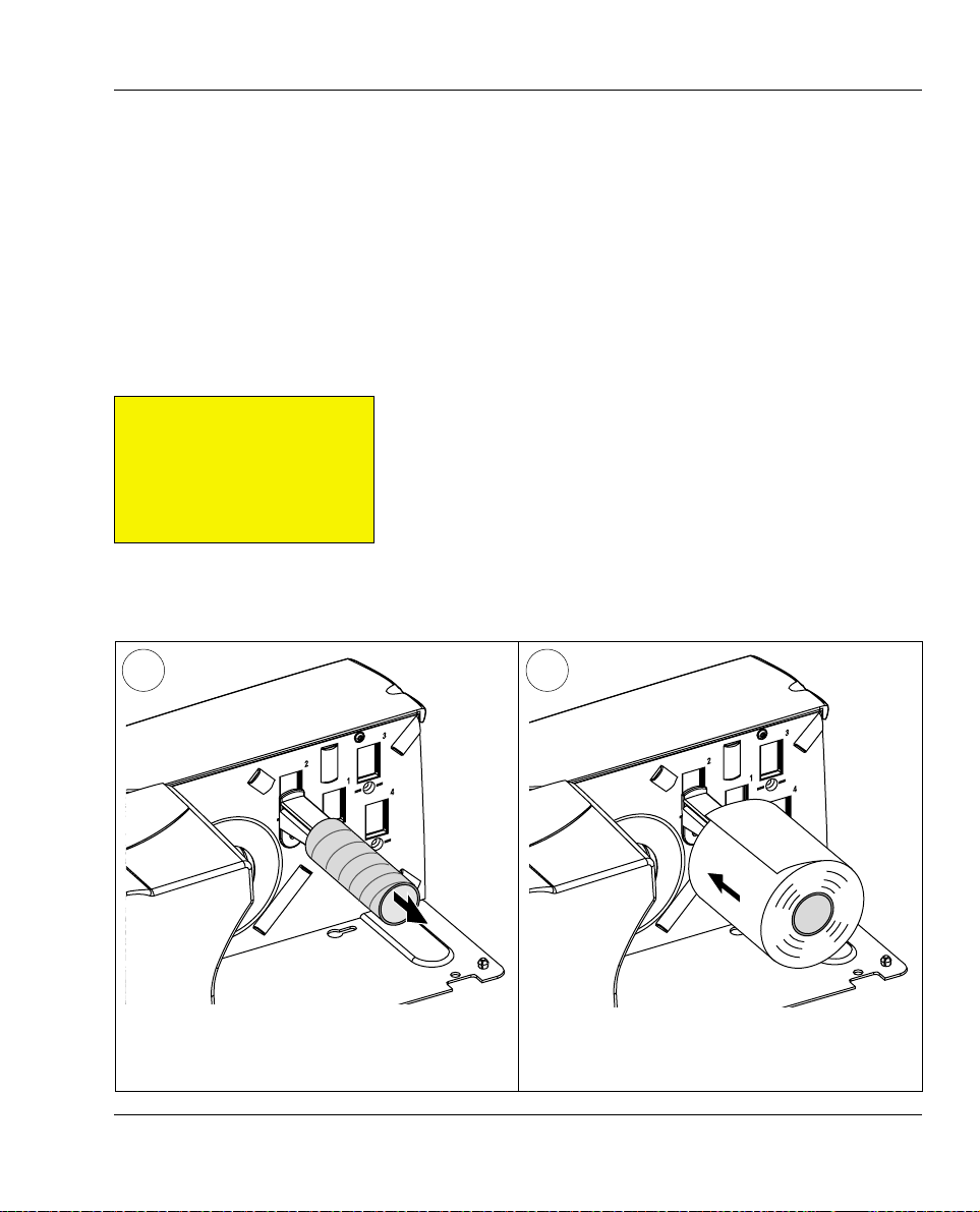
3 4
Chapter 5 Ribbon Load
In case of ribbon reload, remove any used
ribbon and empty ribbon core.
Unpack a roll of original Intermec thermal
transfer ribbon.
5 6
Slide the ribbon roll onto the supply hub so the
ink-coated side faces down when the ribbon is
routed through the print mechanism.
Intermec EasyCoder F4 – Installation & Operation IPL Version, Ed. 3 31
Route the ribbon through the print mechanism
and pull out approximately 20 cm (8 inches)
of ribbon.
Page 33

Chapter 6 Setting Up the Printer
Ribbon Load, cont.
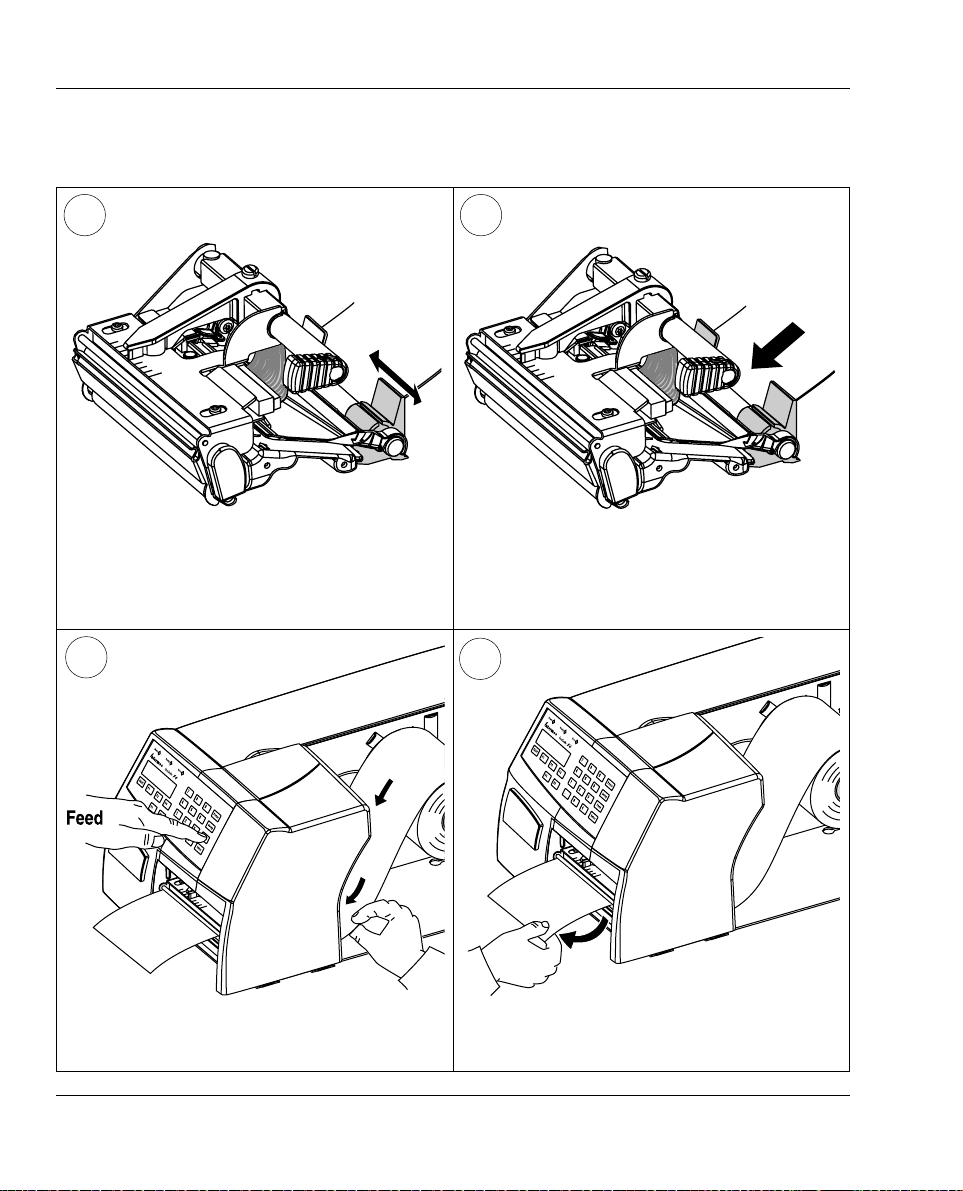
7 8
Without releasing the ribbon, turn the print-
head lift lever counterclockwise to engage the
printhead and lock the ribbon.
ribbon rewind hub so the ribbon is wound up
9 10
Turn the printhead lift lever clockwise to raise
the printhead and release the ribbon.
Intermec EasyCoder F4 – Installation & Operation IPL Version, Ed. 332
Slide the empty cardboard core onto the
when the hub rotates counterclockwise.
Manually advance the ribbon until all of the
transparent leader has passed the printhead
and the ribbon becomes tight.
Page 34

Ribbon Load, cont.
11 12
Turn the printhead lift knob counterclockwise
to engage the printhead.
Chapter 5 Ribbon Load
Close the side door.
Intermec EasyCoder F4 – Installation & Operation IPL Version, Ed. 3 33
Page 35

Chapter 6
Setting Up the Printer
Description
Default Setup
The setup controls the pr inter in regard of serial commun ication,
test and service operations, and specifi es which types of media and
ribbon are loaded in the printer.
Check the list below to see if the printer’s default setup matches your
requirements. If not, you will hav e to c hange the setup. To enter the
Setup Mode, press the <Setup> key on the printer’s built-in ke yboard
and follow the instructions in Chapter 7, “Setup Mode.”
The printer is, by def ault, set up according to the list below:
Communication
Baud rate: 9600 bps
Character length: 8 bits
Parity: None
Stop bits: 1 bit
Protocol: XON/XOFF
Test/Service
Testprint: n.a.
Data dump: No
Memory reset: n.a.
Label rest dots: 0
Form adj dots X: 0
Form adj dots Y: 0
Media
Media type: Gap
Paper type: DT
Label length: 1200 dots
Sensitivity: 420
Darkness: 0%
Intermec EasyCoder F4 – Installation & Operation IPL Version, Ed. 334
Page 36

Setup Parameters
Chapter 6 Setting Up the Printer
Serial Communication
• Baud Rate
• Data Bits
• Parity
• Stop Bits
• Protocol
The serial com munication paramet ers control the communication
between the printer and the connected computer or other devices on
the serial port. The serial communication parameters hav e no effect
on parallel communication.
Make sure the printer’s communication parameters match the setup
of the connected device or vice versa. If not, the response from the
printer to the host will be garbled.
Baud Rate
The baud rate is the t ransmission spe ed in bits per second. There
are 8 options:
• 1200
• 2400
• 4800
• 9600 (default)
• 1 9200
• 38400
• 57 600
• 115200
Data Bits
Th is pa rame ter spe cifie s the nu mber of b its th at wil l define a
character.
• 7 Characters ASCII 000 to 127 decimal
• 8 Characters ASCII 000 to 255 decimal (default)
Parity
The par ity decides how the fi rmware will check for transmission
errors. There are four options:
• None (default )
• Even
• Odd
• Space
Stop Bits
The number of stop bits specifi es how many bits will defi ne the end
of a character. There are two options:
• 1 (default)
• 2
Intermec EasyCoder F4 – Installation & Operation IPL Version, Ed. 3 35
Page 37

Chapter 6 Setting Up the Printer
Setup Parameters, cont.
Serial Communication,
cont.
Protocol
• XON/XOFF (default)
In the XON/XOFF protocol, data fl ow cont rol is achie ved by
using XON (DC 1) and XOFF (DC3) characters. Message blocks
are not required to be bracketed by the Sta rt of Text (STX) and
End of T ext (ETX) characters. Howe ver, at power up or after a reset
all characters except ENQ or VT will be ignored until an STX is
detected. The message length in this protocol is unrestricted. That
is, the printer processes information as it is being downloaded and
stops when there is no more information.
XON/XOFF protocol conforms to generally accepted i ndustry
standards. No end-of-message response is sent to the host other
than XOFF. An X O N will be sent on power u p .
Since DC1 and DC3 are used for data fl ow control, the printer status
characters are different than those of the Standard Protocol. If the
host ignores the printer’s X OFF , the printer will resend an XOFF
after receiving every 15 characters from the host.
Condition Character
Buffer already full GS
Printhead raised US
Ribbon fault US
No label stock EM
Buffer now full DC4
Printhead hot SI
Label at strip pin FS
Label skipping DC2
Printing DC2
Intermec EasyCoder F4 – Installation & Operation IPL Version, Ed. 336
Page 38

Setup Parameters, cont.
Chapter 6 Setting Up the Printer
Serial Communication,
cont.
Protocol, cont.
• Intermec Standard Protocol
The Intermec Printer Standard Protocol is a half-duple x protocol.
All data t ransmissions to the printer consist of status inquiry
(ENQ), status dump (VT), or message blocks. Each message
block starts with the Start of Te xt (STX) character and ends with
the End of Text (ETX) char acter. Each message block must be
255 characters or less, including the STX a nd ETX charact ers.
The printer responds to each status inqui ry or message block
with the printer status. The host should check the printer
status before downloading a message block to the printer.
ENQ causes the printer to t ransmit its highest priority status,
while VT instr ucts t he pri nter to tra nsmit al l status t hat applies
in the order of their priority. The possible printer status in
descending priorities are
Condition Character
Buffer already full GS
Printhead raised US
Ribbon fault US
No label stock EM
Buffer now full DC3
Printhead hot SI
Label at strip pin FS
Label skipping DC1
Ready DC 1
Printing DC1
Intermec EasyCoder F4 – Installation & Operation IPL Version, Ed. 3 37
Page 39

Chapter 6 Setting Up the Printer
Setup Parameters, cont.
Test/Service
•
Testprint
•
Data Dump
•
Memory Reset
•
Label Rest Dots
•
Form Adj Dots X
•
Form Adj Dots Y
Testprint
This pa rt of the Setup Mode al lows you to print various ty pes of
test labels. Go to the desired option and select whether you want to
print al l informat ion or just a single format, page, udc, font. Press
<Enter> and the pr inter wil l sta rt pr int ing the test label or labels.
Pre ss the < Pause> butto n to hold the p rint ing temp orar ily. To
resume printing, press <Pause> again. To term inate the pr inting,
press <C>. The follo wing options are available:
• Confi gurat i on
Select between software (SW) and hardware (HW).
The Software Confi guration Label contains:
- Current confi guration parameters stored in the printer’s
memory
- Defi ned pages
- Defi ned formats
- Defi ned graphics
- Defi ned fonts
- Any installed printer options
The Hardware Confi guration Label contains:
- Printer memory information
- Printer mileage
- Printhead settings
- Firmware checksum, program, and version number
• Format
The Format Lab el contains a single format that you can use to
evaluate the print qua lity of a pa rt icula r format. Select between
pri nting a sing le specifi ed format or labels for all the format s
stored in the printer’s memory .
• Page
The Page Label tests the ability of the printer to receive and print
single or multiple pages of label data that is sent from the host.
Select between printi ng a single specifi ed page or labels for all
the pages stored in the printer’s memory .
Intermec EasyCoder F4 – Installation & Operation IPL Version, Ed. 338
Page 40

Setup Parameters, cont.
Chapter 6 Setting Up the Printer
T est/Service, cont.
Testprint, cont.
• UDC
The UDC Label tests the ability of the printer to receive and print
single or mu ltiple user-defi ned characters (bitmap gr aphics) that
are sent from the host. Select bet ween pr i nt i ng a single U DC or
labels for all the UDCs stored in the printer’s memory.
• Font
The Font Label contains all the characters in a single font. Select
between printi ng a single font or labels for all the fonts stored
in the printer’s memor y. The latter uses a lot of media so it is
recommended to test one font at a time.
Data Dump
If data dump is enabled by selecting the “Yes” option, the printer
prints al l data and protocol chara cters received on the serial por t.
An ASC II and h exadeci mal rep resent ation of ea ch chara cter is
printed.
Memory Reset
There are two options. The memory will be reset to factory default as
soon as an op ti o n has bee n selected and <Enter> is pressed. Select
betwee n “All ”, which resets the entire memory and “Confi guration”
which just resets the confi guration part of the memory .
Label Rest Dots
Specifi es where labe ls stop fo r remov al. Use this f or peel-o ff (self -strip)
applications. Allowed range is -30 (furt hest back) to 30 (furthest
forward). Default is 0. Also available as an IPL command (<SI>fn).
Form Adj Dots X
Specifi es where the X-position of the origin should be placed on the
label. Allowed range is - 30 (cl osest to the leading edge) to 30 (furthest
from the leading edge). Default is 0.
Form Adj Dots Y
Specifi es where the Y-position of the origin should be placed on the
label. Allo wed range is - 30 (c losest to the cen ter section) to 30 ( furthest
from the center section). Default is 0 .
Intermec EasyCoder F4 – Installation & Operation IPL Version, Ed. 3 39
Page 41

Chapter 6 Setting Up the Printer
Setup Parameters, cont.
Media
• Media Type
• Paper Type
• Label Length
• Sensitivity
• Darkness
The media pa rameters tell t he fi rmware the character istics of the
media that will b e used, so the printout will be po siti oned correctly
and get the best quality possible.
Media Type
The Media Type parameters control how the label stop sensor (LSS)
and the media feed work. There are three media type options:
• Gap is used for adhesive labels mounted on liner (backing paper)
or continuous paper stock with detection slots. Default.
• Mark is used for labels, tic kets, or strip provided wi th black marks
at the back.
• Continuous is used for continuous stock without any detection
slots or black marks.
Paper T ype
The Pa per Typ e pa ram ete rs co ntr ol how t he t ran sfer r ibb on
mechanism a nd the r ibbon sensor work. There are t wo paper type
options:
• DT (Direct Thermal) is used for heat-sensi tive media without any
need for a thermal transfer ribbon. Default.
• TTR (Thermal Transfer) is used for non heat-sensitive receiving
face materials in combination with a thermal transfer ribbon.
Label Length
The Label Lengt h setup specifi es the length in dots of each copy
along t he media fe ed dir ection (X-c oordin ate). T his is use d for
“label-out” detection.
Sensitivity (Media Sensitivity Number)
This setup parameter specifi es the characteristics of the direct thermal
media or combination of receiving face material and thermal transfer
ribbon, so the pr inter’s fi rmware can opti mize the heati ng of the
printhead and the print speed. Standard supplies from Intermec are
labeled with a 3-digit media sensitivity number (see Appendix 2)
which is used to sp ecify the me dia grade. T he media sensitivity
number can also be changed using PrintSet, third-party software, or
an IPL command (<SI>gn[,m]). Default is 420 for direct thermal
printing and 567 for thermal transfer printing.
Intermec EasyCoder F4 – Installation & Operation IPL Version, Ed. 340
Page 42

Setup Parameters, cont.
Chapter 6 Setting Up the Printer
Media, cont.
Darkness
Use this para meter to ma ke m inor adjustments of the blackness i n
the printout, for example to adapt the printer to variations in quality
between different batches of the same media quality. The value can
be setwithin the range -10 to 1 0% where -10 is the lightest and 10 is
the darkest. Default value is 0%.
Intermec EasyCoder F4 – Installation & Operation IPL Version, Ed. 3 41
Page 43

Chapter 7
Setup Mode
Entering
Setup Mode
at Installation
Navigating in Setup Mode
To enter the Setup Mode, press the < Setup> key on the printer’s
built-in keyboard. T he following message in th e display window
indicates that you have entered the Setup Mode:
SETUP:
COMMUNICATION
While going th rough the set up procedu re, you are guided by texts
in the printer’s displ ay. Yo u can step bet ween setup pa rameter s,
acknowledge displayed values, select or type new values etc. using
some of the keys on the printer’s keyboard.
Move o ne men u to th e left o n the sam e
level1.
Move one menu t o the rig ht on the sa me
level1.
Move up one level or scroll back in a stack
of options1.
Move down one level or scroll forward in a
stack of options1.
-
Enter numeric values.
Specify negative values (leading position).
Clear erroneously entered values.
Acknowledge and move to next menu.
Print test labels in the T estprint menus.
Exit the Setup Mode.
(Can be used anywhere in the Setup Mode.)
1
/. Lef t, right , up, an d down refer to the o verviews l ater in thi s
chapter.
Intermec EasyCoder F4 – Installation & Operation IPL Version, Ed. 342
Page 44

Setup Mode Overview, Part 1
Chapter 7 Setup Mode
SETUP:
COMMUNICATION
Continued on next page
COMMUNICATION:
BAUDRATE
COMMUNICATION:
DATA BITS
COMMUNICATION:
PARITY
COMMUNICATION:
STOP BITS
COMMUNICATION:
PROTOCOL
BAUDRATE:
9600
19200
38400
57600
115200
1200
2400
4800
DATA BITS:
8
7
PARITY:
NONE
EVEN
ODD
SPACE
STOP BITS:
1
2
PROTOCOL:
XON/XOFF
STANDARD
LEGEND:
Boxes with thick lines indicate default settings.
Intermec EasyCoder F4 – Installation & Operation IPL Version, Ed. 3 43
Page 45

Chapter 7 Setup Mode
Setup Mode Overview, Part 2
Continued from previous page
SETUP:
TEST/SERVICE
SETUP:
MEDIA
TEST/SERVICE:
TESTPRINT
TEST/SERVICE:
DATA DUMP
TEST/SERVICE:
MEMORY RESET
TEST/SERVICE:
LABEL REST DOTS
TEST/SERVICE:
FORM ADJ DOTS X
TEST/SERVICE:
FORM ADJ DOTS Y
MEDIA:
MEDIA TYPE
MEDIA:
PAPER TYPE
MEDIA:
LABEL LENGTH
MEDIA:
SENSITIVITY
MEDIA:
DARKNESS
TESTPRINT:
CONFIG
TESTPRINT:
FORMAT
TESTPRINT:
PAGE
TESTPRINT:
UDC
TESTPRINT:
FONT
DATA DUMP:
NO
YES
MEMORY RESET:
ALL
CONFIGURATION
LABEL REST DOTS:
[0]:
FORM ADJ DOTS X:
[0]:
FORM ADJ DOTS Y:
[0]:
MEDIA TYPE:
GAP
MARK
CONTINUOUS
PAPER TYPE:
DT
TTR
LABEL LENGTH:
[1200]:
SENSITIVITY:
[420]:
DARKNESS:
[0]:
CONFIG:
SW
HW
FORMAT:
ALL
SELECT
PAGE:
ALL
SELECT
UDC:
ALL
SELECT
FONT:
ALL
SELECT
SELECT:
[0]:
SELECT:
[0]:
SELECT:
[0]:
SELECT:
[0]:
Continued on the next page if an EasyLAN 100i interface board is installed.
Intermec EasyCoder F4 – Installation & Operation IPL Version, Ed. 344
Page 46

Setup Mode Overview, Part 3
Continued from the previous page If an optional an EasyLAN 100i interface board
is installed in the printer
Chapter 7 Setup Mode
SETUP:
NETWORK
• Press <Setup> to exit the Setup Mode.
NETWORK:
IP SELECTION
Read
IP SELECTION:
MANUAL
Read
Set
NETWORK:
IP ADDRESS
NETWORK:
NETMASK
NETWORK:
DEFAULT ROUTER
DHCP
BOOTP
RARP
IP ADDRESS:
192.168.1.79
NETMASK:
255.255.255.0
DEFAULT ROUTER:
192.168.1.1
Use <.> and <0> - <9>
to set IP address.
Use <C> to erase.
Use <.> and <0> - <9>
to set netmask.
Use <C> to erase
Use <.> and <0> - <9>
to set default router.
Use <C> to erase.
Intermec EasyCoder F4 – Installation & Operation IPL Version, Ed. 3 45
Page 47

Chapter 8
Options
Introduction
The EasyCoder F4 is designed to provide a high degree of fl exib ilit y
because it has a mo dular design. By add ing options to the basic
printer, the EasyCoder F4 can be adapted for a variety of applications.
Most options can easily be installed by the operator, how e ver, a fe w
should be instal led by a n author i ze d ser v ice te ch n ician or are only
available as factory-installed options.
Covers
(used when a transfer ribbon
mechanism or liner takeup is
not fi tted)
1.5-inch Rotating
Supply Hub
Supply Roll
Post
Label Taken
Sensor
Short Side Door
Long Side Door
Transfer Ribbon
Mechanism
Long Side Door
with 8-inch Megatop
3-inch Adapter
Liner Takeup
and Guide
Shaft
Narrow Quick-Load Guides
Wide Quick-Load Guides
Intermec EasyCoder F4 – Installation & Operation IPL Version, Ed. 346
Page 48

Chapter 8 Options
DTP Model
Side Doors and Megatop
Integral Liner Takeup Unit
Media Supply Hub
In the dedicate d di rect t her ma l pr inti ng (DT P) model, the ther ma l
transfer ribbon mechanism is omitted.
The EasyCoder F4 comes with either a short side door, which only
covers the print mechanism or with one of two types of long side
doors, which encloses the entire media compartment. The standard
long side do or has a fl at top and a slot for externa l media supply.
The 8-inch Megatop version has a hinged transpa rent canopy that
encloses a media roll with a diameter up to 213 mm (8.38 inches).
The stand ard long side door is generally illustrated th roughout t his
manual, but pictures of the short side door can be found in Chapter
4, “Media Load/T ear-off wi th Quick-Load.”
The integral liner takeup unit is an optional device for peel-off
(self-strip) operation, which means that the labels are separated from
a liner (backing paper) after printing and the liner is wound up on an
internal hub. The unit also includes a guide shaft. Peel-off cannot be
combined with Quick-Load guides, see below.
The rotati ng media supply hub is designed to fi t media roll cores
with an internal diameter of 38-40 mm (1.5 inch). The hub can be
fi tted in the same positions as the supply roll post (see Chapter 2,
“Instal lati on.”) Being factory installed, the position of the hub is not
intended to be changed by the operator.
3-inch Adapter
Intermec EasyCoder F4 – Installation & Operation IPL Version, Ed. 3 47
The 3 -inch /76 mm adap ter is with a ro tating m edia supply hub
and makes it possible to use media rolls with 3 inch/ 76 mm inner
diameter cores. The ad apter is pressed onto the med ia supply hub
and secured by a screw.
The 3-inch adapter is not used with a media roll supply post.
Page 49

Chapter 8 Options
Quick-Load Guides
Label Taken Sensor
Interface Boards
For Quick-Load operation (see Chapter 4, “Media Loa d”), a set of
wide or narrow Quick-Load guides is installed at the rear of the print
mechanism instea d of the stand ard edge g uide. The outer gu ide is
adjustable for different media widths. T wo sets of Quick -Load guides
are i ncluded a s stand ard in t he deliver y (either fa ctory-fi tted or
loose). They can easily be installed by the operator:
1. Open the upper media guide (see illustration in Chapter 10,
“Maintenance/Cleaning the Media Guides”).
2. Pull out the standard edge guide from the shaft.
3. Fit the appropriate set of Quick-Load guides onto the shaft as
illustra ted o n th e fi rst page of this chapter.
The L abel Taken Sensor ( LTS) is a phot oelectr ic sensor, which
enables the printer’s fi rmware to detect i f the latest printed label,
ticket, tag etc. has been removed before printing another copy.
A number of different interface boards are available for use with the
EasyCoder F4. The interface boards are either factor y fi tted or can
easily be fi tted b y an a uth orized se rvice techni ci an.
The EasyCoder F4 can accommodate one interface board.
The IPL version of the EasyCoder F4 only support s two of these
interface boards:
• IEEE 1284 Parallel Interface Board
• EasyLAN 100i Interface Board
Refer to Appendix 3, “Interfaces” f or more information.
Intermec EasyCoder F4 – Installation & Operation IPL Version, Ed. 348
Page 50

Chapter 9
Troubleshooting
Symptom Possible Cause Remedy Refer to
Overall weak printout Wrong media grade Change parameter Appendix 2, Chapter 6
Contrast value too low Change parameter Chapter 6
Printhead pressure too low Adjust Chapter 11
Worn printhead Replace printhead Chapter 10
Wrong printhead voltage Replace CPU board ☎ Call Service
Printout weaker on one side Uneven printhead pressure Adjust arm alignment Chapter 11
Weak spots Foreign particles on media Clean or replace Chapters 4 & 5
Media/ribbon don’t match Change to matching media Appendix 4
Poor media or ribbon quality Use Intermec media/ribbon Appendix 2
Worn printhead Replace printhead Chapter 10
Worn platen roller Check/replace ☎ Call Service
Overall dark printout Wrong media grade Change parameter Appendix 2, Chapter 6
Contrast value too high Change parameter Chapter 6
Printhead pressure too high Adjust Chapter 11
Wrong printhead voltage Replace CPU board ☎ Call Service
Excessive bleeding Wrong media grade Change parameter Appendix 2, Chapter 6
Contrast setup value too high Change parameter Chapter 6
Printhead pressure too high Adjust Chapter 11
Faulty energy control Replace CPU board ☎ Call Service
Dark lines along media path Foreign objects on printhead Clean printhead Chapter 10
White lines along media path Printhead dirty Clean printhead Chapter 10
Missing dots on printhead Replace printhead Chapter 10
Large part of dot line missing Failing printhead Replace printhead Chapter 10
Failing strobe signal Check CPU-board ☎ Call Service
Printout missing along inner edge Bad media alignment Adjust Chapter 4
Small core & supply post in upper pos. Move post to lower pos. Chapter 2
Transfer ribbon breaks Ribbon not fi tted correctly Reload ribbon Chapter 5
Wrong media grade (too much energy) Change parameter, Appendix 2, Chapter 6
then clean printhead Chapter 11
Bad energy control Adjust ☎ Call Service
Transfer ribbon wrinkles Faulty ribbon break shaft adjustment Adjust Chapter 11
Incorrect edge guide adjustment Adjust Chapter 4
Too strong printhead pressure Adjust Chapter 11
No thermal transfer printout Ink-coated side does not face media Reload ribbon Chapter 5
Media feed not working properly Changed media characteristics Press Feed Chapter 4
Wrong label rest dots parameter Check/change Chapter 6
Wrong sensor position Check/change Chapter 11
Dirty or blocked sensors Clean media guides Chapter 10
Faulty sensors Replace ☎ Call Service
Intermec EasyCoder F4 – Installation & Operation IPL Version, Ed. 3 49
Page 51

Chapter 10
Maintenance
Printhead Cleaning
Cleaning the pr inthead on a regu lar basis is impor tant for the li fe
of the p rint head a nd for the p rinto ut qual ity. You should cle an
the pr inthead each t ime you replace the r ibbon and media . This
section describes how to clean the print head using cleaning cards.
If additional cleaning is required, for example removing adhesive
residue from the platen roller or tear bar, use a cotton sw ab moistened
with isopropyl alcohol.
Isopropyl alco hol [(CH 3)2CHO H; CA S 67- 63- 0] is a h ighly
fl ammable, moderately toxic, and mildly irritating substance.
1 2
Warning!
Open the side door.
Turn the printhead lift lever clockwise to raise
the printhead.
Intermec EasyCoder F4 – Installation & Operation IPL Version, Ed. 350
Page 52

Printhead Cleaning, cont.
Chapter 10 Maintenance
3
Remove any media and transfer ribbon.
5
4
Open the cleaning card envelope and pull out
the cleaning card. Read the warning text.
6
Insert most of the cleaning card under the
printhead (1). Engage the printhead (2).
Intermec EasyCoder F4 – Installation & Operation IPL Version, Ed. 3 51
Pull out the cleaning card (1) and raise the
printhead (2).
Page 53

Chapter 10 Maintenance
Printhead Cleaning, cont.
87
Wait for approx. 30 seconds to allow the
cleaning fl uid to dissolve the residue.
9
Pull out the cleaning card. If necessary, repeat
the process with a fresh cleaning card.
Intermec EasyCoder F4 – Installation & Operation IPL Version, Ed. 352
Insert most of the cleaning card under the
printhead (1). Engage the printhead (2).
10
Allow the cleaned parts to dry before loading
any media and ribbon.
Page 54

External Cleaning
Chapter 10 Maintenance
1
Always remove the power cord
before cleaning!
3
2
Wipe e xternal surfaces with a soft cloth slightly
moistened with water or a mild detergent.
4
Never spray the printer. Protect it from water
when cleaning the premises.
Intermec EasyCoder F4 – Installation & Operation IPL Version, Ed. 3 53
Never use any sharp tools for removing stuck
labels. The printhead and rollers are delicate.
Page 55

Chapter 10 Maintenance
Cleaning the Media Guides
Both part s of the label stop sensor, which controls the paper feed,
are covered by transparent plastic guides. The g uides have areas,
th rough which th e light betwee n the two par ts of the la bel stop
sensor is transm itted. T hese ar eas (indicate d by a shade of gray in
illustration # 2 below) must be kept clean from dust, stuck labels,
and adhesive residue.
If the printer starts to feed out labels in an unexpected way , raise the
upper guide–as described below–and check for any ob ject that may
block the beam of light (dust, stuck labels, adhesive residue, etc.).
If necessa ry, clean the guides using a cleaning card or a soft cloth
soaked with isopropyl alcohol. Do not use any other chemicals. Be
careful not to scratch the guides.
Isopropyl alco hol [(CH
fl ammable, moderately toxic, and mildly irritating substance.
1 2
Warning!
CHO H; CA S 67- 63- 0] is a h ighly
3)2
Lift the inner part of the upper guide and
pull it outwards,disengaging it from the lower
guide. Take care not to damage the cable.
Intermec EasyCoder F4 – Installation & Operation IPL Version, Ed. 354
Tilt the upper guide upwards and clean the
areas marked with grey. After cleaning, reas-
semble in reverse order.
Page 56

Chapter 10 Maintenance
Printhead Replacement
The pr inthea d is subject to wear bot h from the t herma l transfer
ribbon or the di rect t her ma l med ia a nd from t he rapid heati ng and
cooling process dur ing printi ng. Thus, the printhead wi ll require
periodic rep lace men t.
Time between printhead replacements depends on the print images,
the type of di re ct ther ma l med ia or ther ma l t ra nsfer ribbon in use,
the amount of energy to the printhead, the print speed, the ambient
temperature, and several other factors.
While replacing the printhead, the power should be off.
1 2
Caution!
Turn the printhead lift lever clockwise to raise
Open the side door.
Intermec EasyCoder F4 – Installation & Operation IPL Version, Ed. 3 55
the printhead.
Page 57

Chapter 10 Maintenance
Printhead Replacement, cont.
3
Remove any media and transfer ribbon.
5
4
Pull the printhead bracket away from the
magnet in the pressure arm.
6
Snap-lock
Disconnect the printhead bracket from the print
mechanism as indicated by the arrows and pull
out the printhead as far as the cables allow .
Intermec EasyCoder F4 – Installation & Operation IPL Version, Ed. 356
Disconnect the cables from the printhead. Note
the snap-lock on the inner connector. Pull at the
connectors–not the cables!
Page 58

Printhead Replacement, cont.
Chapter 10 Maintenance
87
Connect the two cables to the replacement
printhead.
9
Turn the printhead lift lever counterclockwise
so the magnet engages the printhead bracket.
Intermec EasyCoder F4 – Installation & Operation IPL Version, Ed. 3 57
Put back the printhead in reverse order and
check that the printhead cables run freely.
10
Load a new supply of media and ribbon, as
described earlier in this manual.
Page 59

Chapter 11
Adjustments
Narrow Media
Adjustment
Screw
Pressure Arm
Center of Media
The printer is factory-adjusted for full-size media width. When using
media less than full width, it is recommended that you adjust the
position of the p re s sure arm so it beco mes ce n t e re d with the m edia.
Thereby, an ev en press ure across the media is obtained.
A poorly adjusted pressure arm may be detected by a w eaker printout
on either s i d e o f the m edi a p ath .
T o ad just the pressure arm, proceed as follo w s:
• Loosen the straight-sl ot scre w that holds the pressure arm. Move
the arm inwards or outwards until the arrow on the tip of the arm
becomes centered with the media.
While moving the arm, push at the part where the screw
is situated, not at the tip. If the arm is hard to move, lift
the printhead and pull the printhead bracket free from the
magnet in the arm.
• After having centred the arm, lock it by tightening the screw.
Note!
In order to provide a better view,
the i llust raton d epicts a d edicated direct thermal printer.
Intermec EasyCoder F4 – Installation & Operation IPL Version, Ed. 358
Page 60

Chapter 11 Adjustments
Label Stop Sensor Position
One Sensor
The label stop /black mark sensor (LSS) is a photoelect ric sensor
that controls the printer’s media feed by dete cting gaps between
labels or slots or black marks in continuous stock, depending on the
printer’s setup in regard of media type (see Chapter 6 “Setting Up the
Printer”). An obvious prerequisite is that the LSS must be aligned
with t he gaps, slots, or bla ck marks. I f using ir regula rly-shaped
labels, align the LSS with the front tips of the labels
The LSS can be moved laterally between 5 fi xed positions. There is
one part of the sensor on top of t h e upp er media guide and another
part underneath the lower guide. These must be adjusted individually
to the same position. Using a small screwdriver, push them inwards
as far as they go and then pull them out–one at the time–while
counting the clicks fr om the snap-locks. A hole in the bottom plate
gives access to the lower sensor part.
The various detect ion points of the sensor in relation to the inner
edge of the media are as follo w s:
One click out 3 mm .1 18 inches
Two clicks out 8 mm .315 inches
Three clicks out 12 mm .472 inches
Four clicks out 16 mm .63 9 inches
Five c licks out 20 mm .787 inches
Upper part of LSS
One Diode + One Sensor
Lower part of LSS
(printhead and headlift shaft omitted for
Intermec EasyCoder F4 – Installation & Operation IPL Version, Ed. 3 59
Print Mechanism
improved visibility)
Page 61

Chapter 11 Adjustments
Printhead Pressure
The pressure of the thermal printhead against the ribbon or media is
factory-adjusted. However, the use of thicker or th inner media than
normal could require the printhead pressure to be readjusted.
Using a straight -slot scre wdriver , turn the adj ustment screw cl ockwise
for more pressure (+ ) or countercl ockwise for less pressure (-). Print
a few labels and check the printout. Increa sed pressure generally
gives a da rker pri ntout and v ice versa. Repe at until t he desir ed
result is obtained.
T o return to the factory setting, tighten the screw (+) as f ar as it goes
and then loosen it (-) six full turns.
Caution!
Do not use a higher printhead pressure than necessary because it
may increase the wear of the printhead and shorten its life.
Adjustment Screw
Intermec EasyCoder F4 – Installation & Operation IPL Version, Ed. 360
Page 62

Chapter 11 Adjustments
Ribbon Break Shaft
Adjustment Screw
If ribbon wrinkling is occurring, you may need to adjust the
alignment of the front ribbon break shaft so that it runs parallel to the
printhead and the ribbon supply and rewind hubs. The adjustment is
done using a straight-slot screw that is located immed iately behi nd
the front ribbon break shaft.
• If the r ibbon tends to slide outwards, turn t he screw carefully
clockwise (fw) to move the outer end of the break shaft
forward.
• If the ribbon tends to slide inwards, turn the screw carefully
counterclockwise (bw) to move the outer end of the break
shaft backward.
Important!
Before readju sting the bre ak shaf t, mak e sure that th ere is no
ot her ca use fo r the wr ink ling of t he ri bbo n (See C hap ter 9,
“Troubleshooting.”)
Ribbon Break Shaft
Intermec EasyCoder F4 – Installation & Operation IPL Version, Ed. 3 61
Page 63

Appendix 1
Technical Data
Printing
Print T echnique Thermal Transfer and/or Direct Thermal
Printhead Resolution 8 dots/mm (203.2 dpi)
Print Speed (variable) 100 to 200 mm/sec. (≈ 4 to 8 inches/sec.)
Print Width (max) 104 mm (4.095 inches) = 832 dots
Print Length (max) 32767 dots = 409.5 cm(16 1 .25 inches)1
Media Width (min/max) 25 to 1 1 4.3 mm ( 1 to 4.5 inches) Standard edge guide
Media Width (min/max) 40/80 to 1 1 4.3 mm ( 1 .57/3. 1 5 to 4.5 inches) Quick-Load guides
Media Roll Diameter (max) 21 3 mm (8.38 inches) Short door/no takeup
Media Roll Core Diameter 38 to 40 mm (1.5 inches) or 76 mm (3 inches)
Ribbon Width (max) 11 0 mm (4 .33 inches)
Ribbon Roll Diameter (outer) 62 mm (2.44 inches) ≈ 200 m (655 ft) ribbon
Ribbon Roll Core Diameter (inner) 25.4 mm ( 1 .00 inches)
Print Directions 4
Modes of Operation
T ear-Off (Straight-through) Yes
Peel-Off (Self-strip) Optional With liner takeup unit
Firmware
Operating System Intermec IPL 3
Built-in fonts (std) 3 scaleable + 21 simulated bitmap fonts
Built-in bar code symbologies (std) 25
Physical Measures
Dimensions (W x L x H) 244 x 397 x 178 mm (9.61 x 1 5.63 x 7.00 inches) With long side door
Weight (excluding media) ≈ 7 kg (1 5.5 pounds) Depending on model
Ambient Operating Temperature +5°C to +40°C (+41 °F to +1 04°F)
Humidity 20 to 80% non-condensing
Electronics
Microprocessor 32 bit RISC
On-board Flash SIMMs 2 sockets for 2 or 4MB each Std. 1 x 2MB
On-board DRAM SIMM 1 Std. 4MB
Power Supply
Mains Voltage >90 to <264 VAC, 45 to 65Hz
PFC Regulation IEC 61000-3-2
Maximum Power Consumption Continuous 1 40W; Peek 300W
Intermec EasyCoder F4 – Installation & Operation IPL Version, Ed. 362
Page 64

Technical Data, cont.
Sensors
Label Gap/Black Mark/Out of Media Y es 5 fi xed positions
Printhead Lifted Yes
Ribbon End Yes
Controls
Control Lamps 3
Display 2 x 16 character LCD w. background light
Keyboard 22 keys membrane-switch type
Print button (1) Does not work with IPL
Beeper Yes
Data Interfaces
Serial 1 x RS-232
Connection for Optional Interface Boards 1
Memory Card Adapter 1 Firmware update only
Accessories and Options
Integral Self-strip Unit with Liner Takeup Optional For peel-off operation
Rotating Media Supply Hub Optional Replaces supply post
3-inch Adapter for Media Supply Hub Optional
Short Side Door Optional
Long Side Door Optional
Long Side Door with 8-inch Roll Cover Optional
Label Taken Sensor Optional
RS-232 Cable Optional
Parallel Interface Board Optional IEEE 1 284
EasyLAN 100i Interface Board Optional Ethernet
Flash Memory Cards Optional Firmware update only
1
/. The max. print length is also restricted by the amount of free DRAM memory.
2
/. Type of door fi tted at delivery depends on model.
2
2
2
Appendix 1 Technical Data
Intermec EasyCoder F4 – Installation & Operation IPL Version, Ed. 3 63
Page 65

Appendix 2
Media Specifi cations
Direct Thermal Media
Thermal Transfer Media
Intermec offers two quality grades of direc t thermal media for
the EasyCoder printers:
• Premium Quality: Top-coated media with high demands on
printout quality and resistance against moisture, plasticisers, and
vegetable o ils. Examples:
- Thermal T op B oard - Duratherm II,
- Thermal T op - Duratherm II T ag
- Thermal T op High Speed - Duratherm Ltg.
- Duratherm IR
• Economy Quality: Non top-coated media with less resistance to
moisture, plasticisers, and vegetable oils. In all other respe cts, it
is equal to Premium Quality. Examples:
- Economy
- Eco Board
Intermec offers stock labels for thermal transfer pri nti ng in a wide
range of quality grades.
• Uncoated papers for economical high-volume printing to be used
with GP/Basewax/Standard ribbons. Examples:
- TTR Uncoated
• Coated papers with various coat-weight, smoothness, and
gloss to be used with HP/ Prem ium and GP/ Basewax/Sta ndard
rib bo n s. Ex am ple s :
- TTR Coated - Duratran II
- TTR Premium - Duratran II T ag
- TTR Premium Board - Duratran II Tag
• Polyet hylene p las ti cs with better resistance to water and many
common chemicals t ha n uncoate d a nd coated pap ers. T hey can
be use outdoors and offer good tear resista nce. Most often used
with HP/Premium ribbons. Examples:
- TTR Polyethylene - Kimdura
- TTR Gloss Polyethyl ene - Syntran
• Polyesters giv e high re sistan ce to c hemical s, heat, and mec hanical
abrasion with HR/Super Premium ribbons. Examples:
- TTR High Gloss P ol y ester - Po ly es ter
Intermec EasyCoder F4 – Installation & Operation IPL Version, Ed. 364
Page 66

Media Roll Size
Appendix 2 Media Specifi cations
Core
Diameters: 38-40 mm (1 .5 inches) or 7 6.2 mm (3 inches)
Width: Must not protrude outside the media
The medi a m u s t be wound u p on t he co re in such a way that the
printer can pull the end free.
Roll
Max. diameter:
- Position 1 152 mm (6.00 inches)
- Position 2 213 mm (8.38 inches)
- Position 3 213 mm (8.38 inches)
Max. width: 114.3 mm (4.50 inches)
Min. width (standard): 25 mm (1.00 inches)
Min. width (Quick-Load): 40/80 mm (1 .57/3 .15 inches)
Max. media thickness: 1 75 µm (0.007 inches)
The maximum recommended media thickness is 175µm. A thicker
media may be used, but print quality will be reduced. The stiffness
is also important and must be balanced against thickness to maintain
print quality.
Media rolls to be loaded inside the printer should be wound with the
printable side facing outwards.
The media supply must not be exposed to dust, sand, gr it, etc. Any
hard particles, how e v er small, can damage the printhead.
Intermec EasyCoder F4 – Installation & Operation IPL Version, Ed. 3 65
Page 67

Appendix 2 Media Specifi cations
Media
Non-Adhesive Strip
⇐ a ⇒ Media Width:
Maximum: 114.3 mm (4.50 inches)
Minimum (standard): 25 . 0 mm (1 . 00 inches)
Minimum (narrow Quick-Load): 40.0 mm (1.5 7 inches )
Minimum ( wide Quick-Load): 80.0 mm (3.1 5 inches )
Media T ype Setup:
• Continuous
• Var length strip
Intermec EasyCoder F4 – Installation & Operation IPL Version, Ed. 366
Page 68

Media, cont.
Appendix 2 Media Specifi cations
Self-Adhesive Strip
⇐ a ⇒ Media Width (including liner):
Maximum: 1 14.3 mm (4.50 inches)
Minimum (standard): 25.0 mm (1. 00 inches)
Minimum (narrow Quick-Load): 40.0 mm (1.5 7 inches )
Minimum ( wide Quick-Load): 80.0 mm (3.1 5 inches )
⇐ b ⇒ Liner
Th e lin er must n ot exte nd mor e tha n a tota l of 1.6 mm ( 0.06
in ches) ou tside t he fac e mate ria l and sh ould p rotr ude e qual ly
on both sides.
⇐ c ⇒ Media Width (excl uding liner):
Maximum: 1 1 2.7 mm (4.4 3 inches)
Minimum: 23.8 mm (0.94 inches)
Media T ype Setup:
• Continuous
Intermec EasyCoder F4 – Installation & Operation IPL Version, Ed. 3 67
Page 69

Appendix 2 Media Specifi cations
Media, cont.
Self-Adhesive Labels
a
c
d
SELF-ADHESIVE
LABELS
b
FEED
DIRECTION
b
⇐ a ⇒ Media Width (including liner):
Maximum: 114.3 mm (4.50 inches)
Minimum (standard): 25 . 0 mm (1 . 00 inches)
Minimum (narrow Quick-Load): 40.0 mm (1.5 7 inches )
Minimum ( wide Quick-Load): 80.0 mm (3.1 5 inches )
⇐ b ⇒ Liner
Th e lin er must n ot exte nd mor e tha n a tota l of 1.6 mm ( 0.06
inches) outside the labels and should protrude equally on both side.
Recommended min. transparency: 40% (DIN 53 147).
⇐ c ⇒ Label Wid th (ex c luding liner):
Maximum: 112.7 mm (4.43 inches)
Minimum: 23.8 mm (0.94 inches)
⇐ d ⇒ Label Length:
Maximum: depends on DRAM size
Minimum: 8.0 mm (0.32 inches)
e
Under ideal circumstances, a minimum label length of 4 mm (0.16
inches) could be used. It requires the sum of the label length (d) and
the label gap (e) to be larger than 7 mm ( 0 .28 inc hes) , th at ba tch
printing is used , a nd th at no pull b ack of t he paper is per form ed.
Intermec does not guarantee that such short labels will work, but it
is up to the user to test this in his unique application.
⇐ e ⇒ Label Ga p:
Maximum: 21.3 mm (0.83 inches)
Recommended: 3.0 mm (0.12 inches)
Minimum: 1.2 mm (0.05 inches)
The Lab el Stop Sensor must be able to det ect the extreme f ront
edges of the labels. It can be moved between 5 fi xed positions at the
following distances from the inner edge of the media.
3 mm (0.11 8 inches )
8 mm (0.31 5 inches)
12 mm (0.4 7 2 inches)
16 mm (0.63 9 inches)
20 mm (0. 7 87 inches)
Media T ype Setup:
• Gap
Intermec EasyCoder F4 – Installation & Operation IPL Version, Ed. 368
Page 70

Media, cont.
Appendix 2 Media Specifi cations
Tickets with Gap
a
b
c
f
d
e
TICKETS & TAGS
FEED
DIRECTION
⇐ a ⇒ Media Width:
Maximum: 114.3 mm (4.50 inches)
Minimum (standard): 25 . 0 mm (1 . 00 inches)
Minimum (narrow Quick-Load): 40.0 mm (1.5 7 inches )
Minimum ( wide Quick-Load): 80.0 mm (3.1 5 inches )
⇐ b ⇒ Cop y Length:
Min. length between slots: 8.0 mm (0.32 inches)
Max. length between slots: depends on DRAM size
Und er ide al circ umst anc es, a mi nimu m tic ket le ngth of 4 m m
(0.16 inches) cou ld be u sed . It requires the su m of t he cop y length
(b) and the detection slit height (e) to be larger than 7 mm ( 0.28
inches), that batch printing is used, and that no pull back of
the pa per is per formed . Inter mec does n ot guaran tee that s uch
short t ickets will work, b ut it is up to the us er to test this in his
unique app l ic at io n.
⇐ c ⇒ LSS Detection Position:
Five fi xed positions (distance from inner edge of the media):
3 mm (0.11 8 inches )
8 mm (0.31 5 inches)
12 mm (0.4 7 2 inches)
16 mm (0.63 9 inches)
20 mm (0. 7 87 inches)
⇐ d ⇒ Detection Slit Length:
The leng th of the dete ction slit (excluding cor ner radi i) must be
minimum 2.5 mm (0.10 inches) on either side of the LSS detection
positio n ( e).
⇐ e ⇒ Detection Slit Height:
Maximum: 21.3 mm (0.83 inches)
Rec o mm e nded : 1 . 6 mm (0.06 inc h e s)
Minimum: 1.2 mm (0.05 inches)
Media T ype Setup:
• Gap
Do not allow any perforation to break the edge of the media as this
may cause the media to split and jam the printer.
Intermec EasyCoder F4 – Installation & Operation IPL Version, Ed. 3 69
Page 71

Appendix 2 Media Specifi cations
Media, cont.
Tickets with Black Mark
a
e
dc
f
g
TICKETS
FEED
DIRECTION
b
⇐ a ⇒ Media Width:
Maximum: 114.3 mm (4.50 inches)
Minimum (standard): 25 . 0 mm (1 . 00 inches)
Minimum (narrow Quick-Load): 40.0 mm (1.5 7 inches )
Minimum ( wide Quick-Load): 80.0 mm (3.1 5 inches )
⇐ b ⇒ Cop y Length:
Maximum: depends on DRAM size
Minimum: 2 0 . 0 mm (0.8 in c he s )
⇐ c ⇒ LSS Detection Position:
Five fi xed positions (distance from inner edge of the media):
3 mm (0.11 8 inches )
8 mm (0.31 5 inches)
12 mm (0.4 7 2 inches)
16 mm (0.63 9 inches)
20 mm (0. 7 87 inches)
⇐ d ⇒ Black Mark Width:
The detectable width of the black ma rk should be at least 5.0 mm
(0.2 inches) on either side of the LSS detection point.
⇐ e ⇒ Black Mark Length:
Maximum: 21.3 mm (0.83 inches)
Comm on: 12 .5 mm (0.5 in che s )
Minimum: 5. 0 mm (0.2 inches)
⇐ f ⇒ Black Mark Y-Position:
It is recommended t hat you place the black ma rk as close to the
front edge of the ticket as possible and use a negative Stop Adjust
value t o contr ol the med ia feed , so the t ickets ca n be prop erly
torn or cut off.
Media T ype Setup:
• Mark
The black mark should be non-refl ective carbon black on a whitish
background. Do not allow any perforations to break the edge of the
media as this may cause the media to split and jam the printer.
Intermec EasyCoder F4 – Installation & Operation IPL Version, Ed. 370
Page 72

Appendix 2 Media Specifi cations
Transfer Ribbons
Important!
Intermec thermal transfer ribbons are eng ineere d specifi cally
for the EasyCoder printheads.
Interm ec offer three t ypes of therma l transfer ribbons opti mized
for different purposes:
• General Purpose (GP)/Standard transfer ribbons allow high
speed printing and give a good printout, but are somewhat
sensitive to smeari ng. They may be the best choice for uncoated
and c o at ed p a p er s .
• High Perfor m a nce ( HP )/Pr em i um transfer ribbons allow high
speed printing and give a highly readable and defi ned printout on
most face materials with smooth surfaces. They have good “smear
resistance” and are most suitable for intricate logotypes and images
on matte-coated papers and synthetic face materials.
• High Resistance (HR)/Super Premium transfer ribbons give an
extremely durable printout, which is resistant to most chemical
agents and high temperatures. Howe v er, s uch transfer ribbons set
high demands on the receiving face material, which must be very
smooth, such as polyesters.
The use of HR/Super Premium ribbons requires t h e print speed
and the energy su pplied b y the printhe ad to be con trolled with gre at
accuracy according to the receiving face material. Custom-made
setup options adapted for special applications can also be created.
Consult your Intermec distributor.
Intermec EasyCoder F4 – Installation & Operation IPL Version, Ed. 3 71
Page 73

Appendix 2 Media Specifi cations
Setting the Media Sensitivity Number
Media sensitivity is importa nt because you use it to optimi ze pr int
qual ity and pr int spe ed. The t hree -digit se nsitivity sp ecifi es the
amou nt of heat requi red by the pr inthea d to image a lab el. The
amount of heat that each roll of media or ribbon requires is unique
due to different chemistries and manufacturing processes.
Int erme d has develope d heati ng sched ules (th e amount of h eat
required to image a label) to produce the highest possibl e print quality
for Intermec med ia and r ibbon combinations on I nter mec pr i nters.
Look for the three-digit media sensitivity number on:
• The side of the media roll. Use the last three d igits (140 in the
• A small label attached to the roll of media.
• A small label attached to the plastic bag of your ribbon roll.
example below) of the 15-digit number stamped on the roll for
the media sensitivity number.
120066102605140
120066102605140
INTERMEC MEDIA PRODUCTS
SENSITIVITY LABEL
56
Intermec
SENSITIVITY NUMBER
57
Use this three-digit number to optimize print quality and print speed
on your printer. You can achieve the best print quality on the printer
by using Intermec ribbon and media products.
The d efault pri nter set ting for di rect th erma l media is 420. Fo r
thermal transfer media, the default setting is 567 . Use the information
on the packaging that you saved when loading media and ribbon to
determine the correct sensitivity number.
Use the Setup Mode (see “Sensitivity” in Chapter 6-7), Pr intSet,
your third-pa rty software, or the I ntermec pri nter language (IPL)
command set to change the med ia sensitivity number. For help on
how to set the media sensitivity number using the printer command
set, see the DOS example on the following page.
Intermec EasyCoder F4 – Installation & Operation IPL Version, Ed. 372
Page 74

Appendix 2 Media Specifi cations
Setting the Media
Sensitivity
Number, cont.
The sensitivity number on each roll of therma l transfer media or
ribbon has an a sterisk (*) in place of one of the digits. To optimize
the se nsitivity numb er for ther mal tr ansfer med ia, you combine
the digits as in this example.
Media or Ribbon Sensitivity Rating Description
Thermal transfer media 56* The asterisk for the third digit
Thermal transfer ribbon 5*7 The asterisk for the second
567 Optimum sensitivity rating
To set th e sens itivit y rat ing for d ire ct th erm al me dia, u se th e
three -digit sensitivity rating located on the roll of media or listed
in t he Dire ct Ther mal Me dia Sensit ivity Set tings t able, late r in
this c ha p t er.
T o use DOS to set the media sensitivity number on a PC
1. At the DOS prompt, type the following command and press
MODE CO M1 96,E,7,1,N
2. T ype the follo wing command lines and press Enter:
COPY CON COM1
<STX><SI>g1,567<ETX>^Z
where:
<SI>g1,567 sets the media sensitivity number to 567.
is reserved to identify the
ribbon’s sensitivity number.
digit is reserved to identify the
media’s sensitivity number.
Enter:
Intermec EasyCoder F4 – Installation & Operation IPL Version, Ed. 3 73
Page 75

Appendix 2 Media Specifi cations
Setting the Media Sensitivity Number, cont.
Direct Thermal Media Sensitivity Settings
Approximate Sensitivity Ratings Setting Direct Thermal Media
400 Series Medium Sensitivity 480 Duratherm Lightning IR Tag
470 Duratherm Lightning-2
460 European IR
450 Duratherm IR Lightning-1
440 European Thermal
420 Duratherm Lightning-1
100 Series Low Sensitivity 180 Duratherm Lightning II- 1
170 European Tag
160 Duratherm II Tag
140 European Top
130 Duratherm II-2
Thermal Transfer Media and Ribbon Sensitivity Settings
Approximate Sensitivity Ratings Setting Media/Ribbon Stock
800 Series High Sensitivity (Paper) 864 European Uncoated/Standard
600 Series Medium Sensitivity (Plastic) 687 Duratran TTR Poly . or Valeron/Premium-3/6/7
677 Duratran Syntran/Premium-3/6/7
633 European Polyethylene/Premium
627 Duratran Kimdura/Premium-3/6/7
623 European Duratran Kimdura/Premium
500 Series Medium Sensitivity (Paper) 56 7 Duratran II- 1/Premium-3/6/7
527 Duratran II Tag-7mil/Premium-3/6/7
513 European Coated/Premium
300 Series Low Sensitivity (Plastic) 366 Super Prem. Poly./Super Prem.- 7
Intermec EasyCoder F4 – Installation & Operation IPL Version, Ed. 374
Page 76

Interfaces
Appendix 3
RS-232 Interface
The E asyCod er F4 has, a s stand ard, o ne seria l commu nicat ion
interfac e: R S-23 2 .
Default Communication Setup
Baud rate: 9600
Char. length 8 bits
Parity: None
Stop bits: 1
Protocol: XON/XOFF
To change th e seria l inte rface s etti ngs, see C hapter 6 , “Setting
Up the Printer.”
Interface Cable
Computer end: DB-9pin or DB-25pin female connector(PC)
Printer end: DB-25pin male connector
Host EasyCoder F4 Host
Signal DB-9 DB-25 Signal DB-25 DB-25 Signal
1 1 1 1 shield
RXD 2 2 TXD 2 3 RXD
TXD 3 3 RXD 3 2 TXD
CTS 8 4 RTS 4 5 CTS
RTS 7 5 CTS 5 4 RTS
6 DSR 6 20 DTR
GND 5 7 Signal GND 7 7 GND
16 + 5V1 16
DSR 6 20 DTR 20 6 DSR
22 RI 22
1
/. The exter nal +5V is l imited t o 200 mA a nd is automat ically
switched off at ov erl oad.
RS-232 Port
Intermec EasyCoder F4 – Installation & Operation IPL Version, Ed. 3 75
Page 77

Appendix 3 Interfaces
IEEE 1284 Parallel Interface Board
Parallel Port
The EasyCoder F4 ca n optionally be fi tted with an IEEE 1284-I
compatible parallel interface board1.
Interface Cable Connectors
Computer end: Depends on type of host computer.
Printer end: 36-pin female IEEE 1284B Centronics
Pin Signal Name
1 DStrobe
2–9 Data 0–7
10 Ack
11 Busy
12 PE
13 Select
14 AF
15 Not connected
16 Ground
17 Screen
18 +5V Ext
19–30 GND
31 Init
32 Error
33-35 Not connected
36 Selectin
1
/. Nibble, byte, ECP, and EPP
from printer to host are presently
not supported.
Intermec EasyCoder F4 – Installation & Operation IPL Version, Ed. 376
Page 78

Appendix 3 Interfaces
EasyLAN 100i Interface Board
The I nterme c EasyLAN 100 i Ether net inter face boa rd provides
the printer with a 10BaseT Ethernet or 100BaseTX Fast Ethernet
network connection. You can commun icate with the printer via a
LAN (Local Area Network) or provide the printer with its own home
page, so you can reach the printer using a Web bro wser.
EasyLAN 100i supports most major computer sy stems and environments. You can assign passwords to restrict both login and pri nter
access. The inter nal EasyLA N 100i Web pages allow you to continuously monitor printer status and to upgrade the fl ash memory of
the printer when new fi rmware becomes available.
EasyLAN 100i supports SNMP for remote monitoring.
When an EasyLAN 100i interface board is installed in the printer,
some extra menus will be added to the Set up Mode (see Chapter
7, “Setup Mode”).
RJ-45
socket
Intermec EasyCoder F4 – Installation & Operation IPL Version, Ed. 3 77
Page 79

Appendix 4
Supported IPL-3 Commands
IPL C o m ma n d Syn ta x
Abort Print Job ....................................................................................................................................... <EM>
Advanced Mode, Select .....................................................................................................................<ESC>C
Alphanumeric Field Separator ................................................................................................................ <GS>
Amount of Storage, Defi ne ....................................................................................................................<SI>N
Auto- Transmit 1, Enable ......................................................................................................................<ESC>j
Auto- Transmit 2, Enable .....................................................................................................................<ESC>d
Auto- Transmit 3, Enable .....................................................................................................................<ESC>e
Auto- Transmit 1, 2, and 3, Disable .....................................................................................................<ESC>k
Bar Code, Select T ype ......................................................................................................................................c
Bar Code Field, Create or Edit .......................................................................................................................B
Batch Count, Set .......................................................................................................................................<US>
Bitmap Cell Height for Graphic or UDF , Defi ne ...........................................................................................y
Bitmap Cell Width for Graphic or UDF, Defi ne ............................................................................................x
Bitmap User-Defi ned Font, Clear or Defi ne .................................................................................................. T
Border Around Human-Readable Text, Defi ne ..............................................................................................b
Box Fiel d, Create or Edit ................................................................................................................................W
Character Bi tmap Origin Offset, Defi ne ........................................................................................................ X
Character Rotation or Bar Code Ratio, Defi ne ................................................................................................r
Clear All Data .......................................................................................................................................<CAN>
Clear Data From Current Field .............................................................................................................<DEL>
Code 39 Prefi x Character, Defi ne ................................................................................................................... p
Command Tables, Load ..................................................................................................................................C
Command Terminator .......................................................................................................................................;
Command Terminator 1 .......................................................................................................................<NUL>
Command Terminator 2 ...........................................................................................................................<LF>
Communication Port Confi gu r ation, Set ...............................................................................................<SI>P
Confi guration Parameters, Transmit .................................................................................................<ESC>p
Current Edit Session, Sa v e ..............................................................................................................................N
Cut ............................................................................................................................................................ <SO>
Cutter, Enable or Disable ........................................................................................................................ <SI>c
Dark Adjust ......................................................................................................................................................K
Dark Adjust, Set .......................................................................................................................................<SI>d
Data Shift - International Characters ...................................................................................................<SUB>
Data Source for Format in a Page, Defi ne ......................................................................................................e
Direct Graphics Mode, Select .............................................................................................................<ESC>g
Emulation Mode, Enter .......................................................................................................................<ESC>c
Emulation or Advanced Mode on Pow er - Up ........................................................................................<SI>C
End-of-Print Skip Distance, Set ............................................................................................................<SI>D
Error Code, Request ..............................................................................................................................<BEL>
Factory Defaults, Reset ...................................................................................................................................D
Intermec EasyCoder F4 – Installation & Operation IPL Version, Ed. 378
Page 80

Supported IPL-3 Commands, cont.
IPL Comm and Syntax
Field, Delete .....................................................................................................................................................D
Field, Select ..........................................................................................................................................<ESC>F
Field Data, Defi ne Source ................................................................................................................................d
Field Decrement, Set ..........................................................................................................................<ESC>D
Field Direction, Defi ne ......................................................................................................................................f
Field Increment, Set ..............................................................................................................................<ESC>I
Field Origin, Defi ne ..........................................................................................................................................o
First Data Entry Field, Sel ect ...............................................................................................................<A CK>
Font, Transmit ......................................................................................................................................<ESC>v
Font Character Width, Defi ne ........................................................................................................................ Z
Font Type, Select ..............................................................................................................................................c
Form Feed .................................................................................................................................................<FF>
Format, Create or Edit .............................................................................................................................A or F
Format Direction in a Page, Defi ne ................................................................................................................. q
Format, Erase ................................................................................................................................................... E
Format, Select ..................................................................................................................................... <ESC>E
Format, Transmit .................................................................................................................................<ESC>x
Format Direction in a Page, Defi ne ................................................................................................................. g
Format Offset Within a Page, Defi ne ............................................................................................................. O
Format Position From Page, Delete ................................................................................................................m
Format Position in a Page, Assign .................................................................................................................M
Formats, Print ....................................................................................................................................................f
Graphic Type, Select ........................................................................................................................................c
Graphic or UDC, Defi ne ..................................................................................................................................u
Hardware Confi guration Label, Print .............................................................................................................h
Height Magnifi cation of Bar, B o x, or UDC, Defi ne ......................................................................................h
Human-Readable Field, Create or Edit ..........................................................................................................H
IBM Language Translation, Enable or Disable ......................................................................................<SI>i
Increment and Decrement, Disable ...................................................................................................<ESC>N
Intercharacter Space for UDF, Defi ne .............................................................................................................z
Interpretiv e Fie ld, Edit .......................................................................................................................................I
Interpretiv e Fie ld, Enab le or Disabl e................................................................................................................ i
Label and Gap Length, Transmit ......................................................................................................<ESC>L
Label Path Open Sensor Value, T ransmit ...................................................................................................... L
Label Rest Point, Adjust ...........................................................................................................................<SI>f
Label Retract, Enable or Disable ........................................................................................................... <SI>R
Label Retract Distance, Set ......................................................................................................................<SI>r
Label Stock Type, Select .........................................................................................................................<SI>T
Label Taken Sensor Value, T ransmit ............................................................................................................. T
Length of Line or Box Field, Defi ne ................................................................................................................l
Appendix 4 Supported IPL-3 Commands
Intermec EasyCoder F4 – Installation & Operation IPL Version, Ed. 3 79
Page 81

Appendix 4 Supported IPL-3 Commands
Supported IPL-3 Commands, cont.
IPL C o m ma n d Syn ta x
Line Field, Create or Edit ................................................................................................................................L
Maximum Label Length, Set .................................................................................................................<SI>L
Media Fault Recov ery Mode, Set ...........................................................................................................<SI>e
Media Sensitivity , Sel ect .........................................................................................................................<SI>g
Memory Usage, Transmit ..................................................................................................................<ESC>m
Next Data Entry Field, Select .................................................................................................................<CR>
Number of Image Bands, Set ...................................................................................................................<SI>I
Numeric Field Separator .......................................................................................................................... <FS>
Options Selected, Transmit ................................................................................................................<ESC>O
Outline Font, Clear or Create .......................................................................................................................... J
Outline Font, Download ...................................................................................................................................j
Page, Create or Edit ..........................................................................................................................................S
Page, Delete .......................................................................................................................................................s
Page, Select .........................................................................................................................................<ESC>G
Page, Transmit .....................................................................................................................................<ESC>y
Pages, Print .......................................................................................................................................................p
Pitch Label, Print .............................................................................................................................................C
Point Size, Set ...................................................................................................................................................k
Postamble, Set ........................................................................................................................................<EOT>
Preamble, Set ........................................................................................................................................<SOH>
Print ........................................................................................................................................................<ETB>
Print Line Dot Count Limit, Set ......................................................................................................................v
Print Quality Label, Print ...............................................................................................................................Q
Print Speed, Set .......................................................................................................................................<SI>S
Printer Language, Select ..........................................................................................................................<SI>l
Printhead Loading Mode, Select ............................................................................................................<SI>h
Printhead Parameters, Transmit ........................................................................................................<ESC>H
Program Mode, Enter ..........................................................................................................................<ESC>P
Program Mode, Exit ........................................................................................................................................R
Program Number, Transmit ..............................................................................................................<ESC>M
Quantity Count, Set ..................................................................................................................................<RS>
Refl ective Sensor Value, Transmit ................................................................................................................M
Remaining Quantity and Batch Count, Transmit ............................................................................<ESC>Q
Reset .......................................................................................................................................................<DLE>
Self-Strip, Enable or Disable ....................................................................................................................<SI>t
Software Confi guration Label, Print ............................................................................................................... s
Start and Stop Codes (Code 39), Print ....................................................................................... <ESC><SP>
Status Dump ............................................................................................................................................ <VT>
Status Enquiry ......................................................................................................................................<ENQ>
T est and Service Mode, Enter .............................................................................................................<ESC>T
Intermec EasyCoder F4 – Installation & Operation IPL Version, Ed. 380
Page 82

Supported IPL-3 Commands, cont.
IPL Comm and Syntax
T est and Service Mode, Exit ...........................................................................................................................R
T op o f Form, Set ......................................................................................................................................<SI>F
Transmissive Sensor Value, T ransmit ............................................................................................................G
User-Defi ned Characters (UDC) and Graphics, Print ...................................................................................g
User-Defi ned Character, Clear or Create .......................................................................................................G
User-Defi ned Character Field, Create or Edit ...............................................................................................U
User-Defi ned Characters, Transmit ....................................................................................................<ESC>u
User-Defi ned Font Character, Create ...............................................................................................................t
User-Defi ned Fonts, Print .................................................................................................................................t
W arm Boot ................................................................................................................................................<BS>
Width of Line, Box, Bar, or Character, Defi ne ..............................................................................................w
Appendix 4 Supported IPL-3 Commands
Intermec EasyCoder F4 – Installation & Operation IPL Version, Ed. 3 81
Page 83

Notes
Intermec EasyCoder F4 – Installation & Operation IPL Version, Ed. 382
 Loading...