

Page 1

User’s Manual
P/N 068749-003
Intermec Ethernet Adapter
Page 2

Intermec Technologies Corporation
6001 36th Avenue West
P.O. Box 4280
Everett, WA 98203-9280
U.S. service and technical support: 1.800.755.5505
U.S. media supplies ordering information: 1.800.227.9947
Canadian service and technical support: 1.800.688.7043
Canadian media supplies ordering information: 1.800.268.6936
Outside U.S. and Canada: Contact your local Intermec service supplier.
The information contained herein is proprietary and is provided solely for the purpose of allowing customers
to operate and/or service Intermec manufactured equipment and is not to be released, reproduced, or used for
any other purpose without written permission of Intermec.
Information and specifications in this manual are subject to change without notice.
1998-1999 by Intermec Technologies Corporation
All Rights Reserved
The word Intermec, the Intermec logo, JANUS, IRL, TRAKKER, Antares, Adara, Duratherm, EZBuilder,
EasyCoder, Precision Print, PrintSet, Virtual Wedge, and CrossBar are either trademarks or registered
trademarks of Intermec.
AIX, Apple, DEC, DOS, Ethernet, EtherTalk, HP, IBM, JetAdmin, Internet Explorer, LAN Manager, LAN
Server, LANtastic, Macintosh, Microsoft, MVS, NDPS, Netscape, Novell NetWare, OS/2, OS/400, PostScript,
SCO, UNIX, VM, VMS, VSE, Windows, AXIS NetPilot, and AXIS ThinServer are registered trademarks of
the respective holders.
Throughout this manual, trademarked names may be used. Rather than put a trademark ( or ) symbol in
every occurrence of a trademarked name, we state that we are using the names only in an editorial fashion, and
to the benefit of the trademark owner, with no intention of infringement.
Page 3

Manual Change Record
This page records the changes to this manual. The manual was originally released as version 001.
Version Date Description of Change
002 2/99 Added information on the internal Ethernet adapter Part No. 069227 and a
procedure for printing a test label in Data Line Print mode.
003 3/99 Added information to configuring using AXIS NetPilot.
iii
Page 4

Page 5

Contents
Contents
Before You Begin xi
Warranty Information xi
Safety Summary xi
Warnings, Cautions, and Notes xii
About This Manual xii
Introducing the Ethernet Adapter
1
2
Overview 1-3
Physical Description 1-4
Computer Environments 1-5
Installing and Integrating 1-6
Configuring and Managing 1-6
Features and Benefits 1-6
Using the Test Button 1-7
Connecting the Ethernet Adapter
Connecting the Ethernet Adapter to Your Network 2-3
Guide to Installing the Ethernet Adapter on Your Network 2-3
Installation Summary 2-4
Setting Up With AXIS NetPilot 2-5
Installing AXIS Print Utilities 2-5
Using AXIS NetPilot 2-5
Setting Up for TCP/IP 2-7
Downloading the IP Address 2-8
Using DHCP in Windows 2-9
Using ARP in Windows 95, 98, or NT 2-9
Using ARP in UNIX 2-10
Using RARP in UNIX 2-10
Using BOOTP in UNIX 2-11
Assigning a Host Name to the IP Address 2-12
Installing the LPR Spooler 2-12
Configuring the Centronics Interface Timing 2-13
Printing a Test Label 2-13
v
Page 6

Intermec Ethernet Adapter User’s Manual
Setting Up the Ethernet Adapter for a NetWare
3
4
Network
Setting Up Your Ethernet Adapter Using NDPS 3-3
Printing Methods 3-4
Print Server Mode 3-4
Remote Printer Mode 3-4
Advanced Installation Using AXIS NetPilot 3-4
Setting Up the Ethernet Adapter for a Windows
Network
Using the AXIS Print Monitor for Windows 95, 98, and NT 4-3
About the AXIS Print Monitor 4-3
Printing Environments 4-3
Peer-to-Peer Printing 4-3
Client/Server Printing 4-4
User Dialog 4-4
Using the AXIS Print Monitor With Windows 95 or 98 4-4
Using the AXIS Print Monitor With Windows NT 4.0 4-6
Using the AXIS Print Monitor With Windows NT 3.5X 4-8
vi
Using the Microsoft LPD Monitor for Windows NT 4-9
Using the Microsoft LPD Monitor With Windows NT 4.0 4-10
Using the Microsoft LPD Monitor With Windows NT 3.5X 4-11
Setting Up the Ethernet Adapter to Use an LPR Spooler 4-12
Using the AXIS Print Utility for Windows 4-12
About AXIS Print Utility for Windows 4-13
Peer-to-Peer vs. Client/Server Printing 4-13
Windows Clients Using LANtastic 4-16
Page 7

Contents
Setting Up the Ethernet Adapter for an OS/2 Network
5
6
7
Using the AXIS Print Utility for OS/2 5-3
Integrating Your Ethernet Adapter Into the OS/2 Environment 5-4
Creating a Print Queue 5-4
Sharing the Print Queue 5-4
Setting Up the Ethernet Adapter for a Macintosh
Network
Installing Using the Chooser Window 6-3
Communications Support and Protocols 6-3
Setting Parameters 6-3
Setting Up the Ethernet Adapter for a UNIX Network
Integrating Into the Host Printer Spooler 7-3
Print Methods on TCP/IP Networks 7-4
Line Printer Daemon 7-5
File Transfer Protocol 7-5
PROS 7-5
PROS A 7-6
PROS B 7-6
Reverse Telnet 7-6
Other Systems 7-6
Other UNIX Systems 7-6
IBM MVS Systems 7-6
Customizing Your Printing 7-7
Converting Character Sets 7-7
Adding Strings Before and After Print Jobs 7-8
Substituting Strings 7-8
Converting ASCII to PostScript 7-9
Reading Back Information 7-10
Debugging Using the Hex Dump Mode 7-10
vii
Page 8

Intermec Ethernet Adapter User’s Manual
Managing and Configuring the Ethernet Adapter
8
Introduction 8-3
Using a Web Browser to Manage and Configure the Ethernet Adapter 8-4
Using AXIS NetPilot to Manage and Configure the Ethernet Adapter 8-6
Starting AXIS NetPilot 8-7
Changing the Parameter Values 8-7
Property Pages 8-7
Parameter List Editor 8-8
Modifying the Network Environments 8-9
Monitoring Printers 8-9
Grouping Logically Connected Adapters 8-10
Finding Printer Information 8-10
Using FTP to Manage and Configure the Ethernet Adapter 8-12
Editing the Configuration File 8-12
Viewing the Status File 8-13
Viewing the Account File 8-13
Using Telnet to Manage and Configure the Ethernet Adapter 8-14
Viewing the Accounting File 8-14
Viewing the Status File 8-15
Performing Resets 8-15
9
Using SNMP to Manage and Configure the Ethernet Adapter 8-16
System Requirements for SNMP 8-16
About AXIS MIB 8-16
Using HP Administration Tools to Manage and Configure the Ethernet Adapter 8-17
Using Other NetWare Configuration Methods 8-17
Printer Status 8-17
Notification 8-18
Print Layout 8-18
Updating the Software
Obtaining Updated Software 9-3
Downloading the Software Over the Internet 9-3
Downloading the Software Over Anonymous FTP 9-3
viii
Page 9

Updating the Flash Memory 9-3
Updating Using the AXIS NetPilot 9-4
Upgrading Over the Network Using FTP 9-4
Configuration Parameters
Contents
A
B
I
Changing the Configuration Parameters A-3
Using AXIS NetPilot A-3
Using a Web Browser A-3
Using FTP A-3
Using FTP for UNIX, Windows, and OS/2 Workstations A-3
Using FTP for Macintosh A-4
Sample Configuration Parameters A-4
Technical Specifications
Software Specifications B-3
Physical Specifications B-4
Index
ix
Page 10

Page 11

Before You Begin
This section introduces you to standard warranty provisions, safety precautions,
warnings and cautions, document formatting conventions, and sources of additional
product information. A documentation roadmap is also provided to guide you in finding
the appropriate information.
Warranty Information
To receive a copy of the standard warranty provision for this product, contact your local
Intermec support services organization. In the U.S. call 1.800.755.5505, and in Canada
call 1.800.688.7043. Otherwise, refer to the Worldwide Sales & Service list that ships
with this manual for the address and telephone number of your Intermec sales
organization.
Safety Summary
Your safety is extremely important. Read and follow all warnings and cautions in this
book before handling and operating Intermec equipment. You can be seriously injured,
and equipment and data can be damaged if you do not follow the safety warnings and
cautions.
Before You Begin
Do not repair or adjust alone Do not repair or adjust energized equipment alone
under any circumstances. Someone capable of providing first aid must always be
present for your safety.
First aid Always obtain first aid or medical attention immediately after an injury.
Never neglect an injury, no matter how slight it seems.
Resuscitation Begin resuscitation immediately if someone is injured and stops
breathing. Any delay could result in death. To work on or near high voltage, you should
be familiar with approved industrial first aid methods.
Energized equipment Never work on energized equipment unless authorized by a
responsible authority. Energized electrical equipment is dangerous. Electrical shock
from energized equipment can cause death. If you must perform authorized emergency
work on energized equipment, be sure that you comply strictly with approved safety
regulations.
xi
Page 12

Intermec Ethernet Adapter User’s Manual
Warnings, Cautions, and Notes
The warnings, cautions, and notes in this manual use the following format.
Warning
A warning alerts you of an operating procedure, practice, condition, or statement
that must be strictly observed to avoid death or serious injury to the persons
working on the equipment.
Avertissement
Un avertissement vous avertit d’une procédure de fonctionnement, d’une méthode,
d’un état ou d’un rapport qui doit être strictement respecté pour éviter l’occurrence
de mort ou de blessures graves aux personnes manupulant l’équipement.
Caution
A caution alerts you to an operating procedure, practice, condition, or statement
that must be strictly observed to prevent equipment damage or destruction, or
corruption or loss of data.
Conseil
Une précaution vous avertit d’une procédure de fonctionnement, d’une méthode,
d’un état ou d’un rapport qui doit être strictement respecté pour empêcher
l’endommagement ou la destruction de l’équipement, ou l’altération ou la perte de
données.
Notes: Notes are statements that either provide extra information about a topic or
contain special instructions for handling a particular condition or set of circumstances.
About This Manual
This manual contains all of the information necessary to install, configure, and maintain
the Intermec Ethernet adapter.
This manual was written for analysts and system administrators who operate, program,
and connect the Ethernet adapter to a network or system. A basic understanding of your
network, programming, and data communications is necessary.
xii
Page 13

Before You Begin
What You Will Find in This Manual
This table summarizes the information in each chapter of this manual:
Chapter Description
Chapter 1 Gives an overview of how to use the Ethernet adapter and lists features and
benefits.
Chapter 2 Explains how to attach the Ethernet adapter to your printer and network and
set up your Ethernet adapter for TCP/IP protocol in different network
environments.
Chapter 3 Explains how to configure your Ethernet adapter in a NetWare network.
Chapter 4 Explains how to configure your Ethernet adapter in a Windows network.
Chapter 5 Explains how to configure your Ethernet adapter in an OS/2 network.
Chapter 6 Explains how to configure your Ethernet adapter in a Macintosh network.
Chapter 7 Explains how to configure your Ethernet adapter in a UNIX network.
Chapter 8 Describes how you can change the Ethernet adapter parameter values.
Chapter 9 Explains how to obtain and update the software on the Ethernet adapter.
Appendix A Explains how to change the parameter values and provides a sample
configuration file.
Appendix B Provides a list of the software and hardware specifications for the Ethernet
adapter.
Terminology
You should be aware of how these terms are being used in this manual:
Term Description
Ethernet adapter The generic term “Ethernet adapter” indicates both the external
and internal Ethernet adapter. More specific terms, such as
“external Ethernet adapter,” indicate one or the other type of
Ethernet adapter.
Environment “Environment” indicates the operating system of the network,
such as Windows or Macintosh.
Printer “Printer” refers to any Intermec bar code label printer.
xiii
Page 14

Intermec Ethernet Adapter User’s Manual
Format Conventions for Input From a Keyboard
This table describes the formatting conventions for input from PC or host computer
keyboards:
Convention Description
Special text Shows the command as you should enter it into the reader. See
Italic text Indicates that you must replace the parameter with a value. See
“Format Conventions for Commands” later in this chapter.
“Format Conventions for Commands” later in this chapter.
Bold
text
Indicates the keys you must press on a PC or host computer
keyboard. For example, “press
labeled “Enter” on the PC or host computer keyboard.
” means you press the key
Enter
Format Conventions for Commands
This manual includes sample commands that are shown exactly as you should type
them on your PC or host computer. The manual also describes the syntax for many
commands, defining each parameter in the command. This example illustrates the
format conventions used for commands:
To start a DOS window, type the following command:
arp -s
ping
arp -d
where:
nnn.nnn.n.nnn is the IP address for the Ethernet adapter
nn-nn-nn-nn-nn-nn is the Ethernet address for the Ethernet adapter
This table defines the conventions used in the example:
Convention Description
nnn.nnn.n.nnn nn-nn-nn-nn-nn-nn
nnn.nnn.n.nnn
nnn.nnn.n.nnn
Special font Commands appear in this font. You enter the command exactly as it
Italic text Italics indicate a variable, which you must replace with a real value,
[ ] Brackets enclose a parameter that you may omit from the command.
Required
parameters
where This word introduces a list of the command’s parameters and
xiv
is shown.
such as a number, filename, or keyword.
Do not include the brackets in the command.
If a parameter is not enclosed in brackets [ ], the parameter is
required. You
otherwise, the command will not execute correctly.
explains the values you can specify for them.
include the parameter in the command;
must
Page 15

Before You Begin
Other Intermec Manuals
You may need additional information when working with the Ethernet adapter in a data
collection system. Please visit our web site at www.intermec.com to access many of our
current manuals in PDF format. To order printed versions of the Intermec manuals,
contact your local Intermec representative or distributor.
xv
Page 16

Page 17

1
Introducing the Ethernet Adapter
Page 18

Page 19

Overview
code39 code39 Introducing the Ethernet Adapter
This chapter gives an overview of how and where to use your Ethernet adapter and
explains the features of your Ethernet adapter.
The external Ethernet adapter, Part No. 068788, and the internal Ethernet adapters, Part
No. 068789 and 069227, allow you to share your available printer resources with
everyone on your Ethernet network.
You can connect only the external Ethernet adapter to the following Intermec printers
to print labels:
• 91* printers • 601XP printers
• 301* printers • 901* printers
• 401* printers • 4630* printers
• 501*, 501E*, 501S*, and 501XP printers • 7421 and 7422* printers
These printer models require an external power supply to run the external Ethernet
*
adapter.
1
You can connect either the external or the internal Ethernet adapter Part No. 068789 to
the following Intermec printers to print labels:
• 3240* printers
• 3400* and 3440* printers
• 3600* printers
• 4400* printers
These printer models require an external power supply to run the external Ethernet
*
adapter.
For the 3240, 3400, 3440, 3600, and 4400 printers, you must have the parallel
Note:
port option installed on your printer to connect the external Ethernet adapter. The
Ethernet adapter is not compatible with the 4400A, but you can use the adapter with all
later 4400 models.
You can connect the Ethernet adapter Part No. 069227 to the 4420 and 4440 printers.
With the internal Ethernet adapter installed, the parallel port on the 4420 and
Note:
4440 printers is not available for use.
The Ethernet adapter uses a twisted pair (10BaseT) connection with a network speed of
10 Mbps. Throughout the manual, “Ethernet adapter” will be used to refer to both the
internal and external adapter unless specified.
1-3
Page 20

Intermec Ethernet Adapter User’s Manual code39 code39
Physical Description
External Ethernet Adapter
Parallel port
connector
+
Test button
10BaseT
connector
External
power
supply
connector
Internal Ethernet Adapter
I
O
AXISI.002
Network
LED
Power
LED
AXISI.001
Network
LED
Power
LED
Test
button
10BaseT
connector
1-4
Page 21

Physical Description (continued)
Part Function
10BaseT connector Connects the Ethernet adapter to a 10 Mbps Ethernet network via a
code39 code39 Introducing the Ethernet Adapter
10BaseT cable.
1
Parallel port connector
(external Ethernet adapter
only)
Test button Use the Test button to:
Network LED Flashes to indicate network activity.
Power LED Lights up while power is applied. If the power light emitting diode
Provides the external Ethernet adapter with a single high-speed
parallel port that can connect directly, without the need of cabling,
to an Intermec printer with a parallel port installed.
•
Print the print quality label to check the connection to the
printer. This functionality only works with firmware version
5.59 or higher.
• Print the parameter list that shows some of the Ethernet
adapter’s settings. This functionality only works with firmware
version 5.59 or higher.
• Reset the Ethernet adapter’s parameters to the factory default
settings
Refer to “Using the Test Button” later in this chapter for more
information about the Test button.
(LED) is off or flashes, there is a problem with the Ethernet adapter
or its power supply.
.
Computer Environments
The Ethernet adapter is the ideal print server in mixed computer environments as it can
communicate with all the major systems and network protocols including:
• NetWare
• UNIX
• Windows
• Windows clients connected to LANtastic
• OS/2
• Macintosh
• Internet/intranet via any standard Web browser
networks
1-5
Page 22

Intermec Ethernet Adapter User’s Manual code39 code39
Installing and Integrating
You need the appropriate Axis client software, which comes with your adapter, to
install and integrate the Ethernet adapter:
• AXIS NetPilot (NetWare)
• AXIS Print Monitor (Windows 95 or 98)
• AXIS Print Utility for Windows (Windows 3.1 and Windows for Workgroups)
• AXIS Print Utility for OS/2
• axinstall (UNIX)
The Ethernet adapter can be installed in the Macintosh environment without any Axis
software.
Configuring and Managing
Using the Ethernet adapter’s built-in Web server, you can configure and manage the
Ethernet adapter directly from its internal Web pages using hypertext transfer protocol
(HTTP) over transmission control protocol/Internet protocol (TCP/IP). Using any
standard Web browser, you can manage your Ethernet adapter independent of your
network environment.
If your network does not support TCP/IP, you can use the AXIS NetPilot software to
configure the Ethernet adapter in any other environment.
Features and Benefits
Reliability
Flexibility
Speed
Easy to Install
Security
The Ethernet adapter provides high performance and reliability combined with low
power consumption. The electronic circuits are based on the proven AXIS ETRAX
chip that comprises an integrated 32 bit RISC processor and associated network
controllers.
It supports printing in all the major computer systems and environments, including five
different print methods in the TCP/IP environment.
The AXIS ETRAX chip is designed for LAN products and gives you faster throughput
than a direct PC-to-printer connection. With a sustained data throughput of up to 390K
per second, the Ethernet adapter is fast. High speed Centronics communication such as
Hewlett-Packard Fast Mode, High Speed, and IBM
You can install the Ethernet adapter in minutes, using the AXIS NetPilot installation
software. Its Installation Wizard, together with the axinstall script for UNIX
workstations, allows installation into the Ethernet adapter’s networking environments.
You can assign passwords to restrict login and printer access.
Fast Byte is supported.
1-6
Page 23

Features and Benefits (continued)
code39 code39 Introducing the Ethernet Adapter
1
Monitoring
Firmware Upgrades
The provided AXIS NetPilot software and the Ethernet adapter’s internal Web pages
allow you to continuously monitor printer status.
The AXIS Print Monitor for Windows 95, 98, and NT can be configured to display
pop-up messages that show the status of peer-to-peer print jobs.
The Ethernet adapter additionally supports simple network management protocol
(SNMP) for remote monitoring.
You can upgrade the Ethernet adapter’s firmware over the network. This allows you to
quickly update and enhance the operational features of your Ethernet adapter when
new adapter firmware becomes available. All firmware updates are free of charge.
Using the Test Button
The Test button is located on the front right hand side of the external Ethernet adapter
and on the printer’s back panel near the Ethernet cable connector for the internal
Ethernet adapter. With the Test button, you can
• print a print quality label that checks the connection to the printer if you have
firmware version 5.59 or higher. If your Ethernet adapter has a firmware version
lower than 5.59, you can use the Test button to print a print quality label by putting
the printer in Data Line Print mode. Data Line Print mode is available on the
following printer models: 3240, 3400, 3440, 3600, 4400, 4420, and 4440.
• print the parameter list showing some of the Ethernet adapter’s settings. This
functionality works only with firmware version 5.59 or higher.
• reset the Ethernet adapter’s parameters to the original factory default settings.
The functionality of the Test button is determined by the power status of the Ethernet
adapter and the number of times you press the button.
To print a print quality label with the Test button
• If you have firmware version 5.59 or higher, press the Test button once to print a
print quality label.
1-7
Page 24

Intermec Ethernet Adapter User’s Manual code39 code39
Print Quality Label
*CODE393.0/1*
*CODE393.0/1*
CODE 39 3.0 / 1
MODEL
3440
Prog 063755
Version 1.4.3
If the print quality label prints, the Ethernet adapter is communicating with the printer
correctly. You can also use the print quality label to check if the printer is printing
satisfactorily.
To print a print quality label from Data Line Print mode
1. Turn off your printer.
CODE 39
2.5 / 1
*PICKET-FIELD
*PICKET FIELD*
INTERMEC
INTERMEC Corporation
Everett, WA 98203
*SUPPLIER*
CODE 39
3.0 / 1
CODE 39
2.5 / 1
*SUPPLIER*
*PICKET-FIELD*
*PICKET FIELD*
*PICKET-FIELD*
*PICKET FIELD*
Strobe
Sensitivity : 420
Delay : 0 us
Duration : 0 us
On-time : 15 us
Print Speed : 3.0 ips
Darkness Pot : 181
Printhead Temp : 68
AXISI.005
2. Press and hold the Feed/Pause button while you turn on the printer. The printer
prints the hardware configuration test label.
3. Release the Feed/Pause button. The printer is now in Data Line Print mode.
4. Press and release the Test button on the Ethernet adapter. The printer prints each
character with its hexadecimal equivalent underneath.
5. To enter normal Print mode, turn the printer power off and then on again.
1-8
Page 25

code39 code39 Introducing the Ethernet Adapter
To print a parameter list
• If you have firmware version 5.59 or higher, press the Test button twice.
AXIS 540+/542+ V5.56
Jun 3 1998
S/N: 00408C353354
TCP/IP: enabled
IP Address: 999. 999. 999. 999
WINS: enabled
Status: Not Registered
Name: AXIS353354
NetWare: enabled
Print server name: AXIS353354
Microsoft Networks and
LAN Server/Manager: enabled
Printer Name: AX353354. LP1
Apple Ether Talk: disabled
AXIS353354_LPT1
AXIS353354_2
AXISI006
1
The printer prints a label giving the following information on the Ethernet adapter:
• Serial number
• TCP/IP enabled or disabled
• IP address
• WINS enabled or disabled
• Registration status
• Ethernet adapter name
• NetWare enabled or disabled
• Print server name
• Microsoft networks and LAN server
or LAN manager enabled or disabled
• Printer name
• Apple
EtherTalk enabled or disabled
To return to the factory default settings
1. Turn off the printer or remove the power cord to turn off the Ethernet adapter.
2. Press and hold down the Test button.
3. While continuing to press the Test button, simultaneously turn on the Ethernet
adapter by turning on the printer or replacing the power cord. Keep the Test button
pressed for at least 5 seconds after restoring power until the Network LED flashes
at 1-second intervals.
1-9
Page 26

Intermec Ethernet Adapter User’s Manual code39 code39
4. Release the Test button and wait at least five LED flashes.
5. Press and hold the Test button again until the Network LED remains constantly lit.
Restart the Ethernet adapter by turning it off and on. The Ethernet adapter is now reset
to factory default settings.
The node address parameter (NODE_ADDR) and IP address (IP_ADDR) will
Note:
remain unchanged, but all other parameters are reset. If you want to change the node
or IP address, you may do so via the general property page, using the AXIS NetPilot.
1-10
Page 27

2
Connecting the Ethernet Adapter
Page 28

Page 29

code39 code39 Connecting the Ethernet Adapter
This chapter explains how to connect your Ethernet adapter to your network and how
to install and integrate your Ethernet adapter in your network environment. This
chapter also explains how to set up your Ethernet adapter for TCP/IP.
Connecting the Ethernet Adapter to Your Network
Both the internal and external Ethernet adapters are pre-configured with a unique node
address that is identical to the serial number. You can change the node address using
the AXIS NetPilot or any standard Web browser, if required.
You need an external power supply for the external Ethernet adapter on certain
Note:
printers. (See page 1-3 for the models that require an external power supply.) Make
sure that the external power supply is marked with the correct mains voltage. See
Appendix B for the power consumption specifications.
To connect the Ethernet adapter to your network
1. Note the Ethernet adapter’s serial number. The serial number is on the bottom of
the external adapter and on the back panel by the 10BaseT connector on the internal
option. You need the serial number during the network configuration.
2
2. Turn off the printer or disconnect the Ethernet adapter’s external power supply.
3. Plug the external Ethernet adapter into the printer’s parallel port.
4. Connect a 10BaseT cable to the 10BaseT connector.
5. Turn on the printer and, if necessary, connect the external power supply to the
external Ethernet adapter.
The Network LED flashes when the Ethernet adapter is connected to your network. If
the Network LED is not flashing, make sure that the Ethernet adapter is connected
properly and that the correct cable is attached.
If you have firmware version 5.59 or higher, make sure the Ethernet adapter is working
by pressing the Test button to print a print quality label. If you have a firmware version
lower than 5.59, you can print a print quality label by putting the printer in Data Line
Print mode first. For help, see “Using the Test Button” in Chapter 1.
Guide to Installing the Ethernet Adapter on Your Network
After connecting the Ethernet adapter to your network, you are now ready to install the
Ethernet adapter. Choose the method of installation based on your printing
requirements and the type of network you use. Proceed with the appropriate installation
method from the next table.
2-3
Page 30

Intermec Ethernet Adapter User’s Manual code39 code39
Guide to Installing the Ethernet Adapter on Your Network (continued)
Network Installation Procedure
NetWare
Windows If your Windows platform uses NetBIOS/NetBEUI, use the AXIS
OS/2 If your network uses OS/2 workstations, use the AXIS NetPilot only if
To install the Ethernet adapter with NDPS
Ethernet Adapter Using NDPS” in Chapter 3.
To install the Ethernet adapter with basic NetWare settings that are
sufficient for immediate printing, see “Advanced Installation Using
AXIS NetPilot” later in this chapter.
To connect additional printing queues to the printer port or create new
printing queues, see Chapter 3, “Setting Up the Ethernet Adapter for a
NetWare Network.”
NetPilot only if you want to change the default adapter name.
Otherwise, see Chapter 4, “Setting Up the Ethernet Adapter for a
Windows Network.”
If your Windows platform uses TCP/IP, you must initially perform the
basic TCP/IP set up procedures. For help, see “Setting Up for TCP/IP”
later in this chapter before going to Chapter 4.
you want to change the default adapter name. Otherwise, see Chapter 5,
“Setting Up the Ethernet Adapter for an OS/2 Network.”
, see “Setting Up Your
Macintosh If Macintosh computers are used on your network, see Chapter 6,
“Setting Up the Ethernet Adapter for a Macintosh Network.”
UNIX Follow the instructions under “Setting Up for TCP/IP” later in this
chapter before going to Chapter 7, “Setting Up the Ethernet Adapter
for a UNIX Network.”
Installation Summary
The appropriate installation tools for the Ethernet adapter are summarized in the
following table:
Operating System Protocols Installation Tool
Internetwork packet exchange/sequenced packet exchange
(IPX/SPX) (NetWare)
TCP/IP (UNIX) axinstall
TCP/IP (Windows 95/98/NT) AXIS Print Monitor
TCP/IP (Windows) LPR Spooler*
NetBIOS/NetBEUI (Windows 95/98/NT) AXIS Print Monitor
NetBIOS/NetBEUI (Windows) AXIS Print Utility for Windows
NetBIOS/NetBEUI (OS/2) AXIS Print Utility for OS/2
Apple EtherTalk Standard using the Chooser
AXIS NetPilot
* A shareware LPR spooler is available for Windows for Workgroups. You can download this
software from www.axis.com/techsup/.
2-4
Page 31

code39 code39 Connecting the Ethernet Adapter
Setting Up With AXIS NetPilot
AXIS NetPilot is part of the AXIS Print Utilities, which comes on the CD-ROM or
disks shipped with your Ethernet adapter. AXIS NetPilot runs on any of the Windows
platforms:
• Windows 3.1
• Windows 95
• Windows 98
• Windows NT
• Windows for Workgroups
• WinOS/2 window under OS/2
Installing AXIS Print Utilities
Use one of the next procedures to install AXIS NetPilot on your PC or host.
2
To install AXIS Print Utilities on a Windows client
• Run
An installation wizard appears to guide you through the installation.
To install AXIS Print Utilities on an OS/2 client
• Run
An installation wizard appears to guide you through the installation.
n
:\windows\setup
where n is your CD-ROM or disk drive
n
:\os2\install
where n is your CD-ROM or disk drive
Using AXIS NetPilot
When you start AXIS NetPilot, the program searches the network for new Ethernet
adapters that have not yet been installed. For fastest results, make sure the Ethernet
adapter is connected to your printer and your printer is on. If the program finds any new
adapters, you have the option of installing them. To proceed, select the Ethernet adapter
you want to install and start the Axis Installation Wizard.
The parameters entered during installation are not permanent; you can change
Note:
them according to your network printing requirements.
2-5
Page 32

Intermec Ethernet Adapter User’s Manual code39 code39
AXIS NetPilot Installation Wizard
The Axis Installation Wizard guides you through the installation and asks for the
relevant information concerning your network environment. For more information
about AXIS NetPilot, see “Using AXIS NetPilot to Manage and Configure the Ethernet
Adapter” in Chapter 8.
The Wizard prompts you for the following information:
Environments You may choose which networking environments you want to
configure the Ethernet adapter for, such as NetWare, TCP/IP, Windows, OS/2, or
AppleTalk. If your network comprises different platforms, you can enable all five
environments.
NetWare NDS You may place NetWare Print Queues on a specific bindery server or
into an NDS Tree.
Print Queues The default Print Queue names and adapter port names consist of the
adapter name followed by the printer port. The following table provides the default
Print Queue names for different network environments. You can amend the default
names.
Network Environment Default Name
NetWare AXIS1A0003_LPT1_Q
Windows AX1A0003.LP1
AppleTalk AXIS1A0003_LPT1
2-6
Page 33

code39 code39 Connecting the Ethernet Adapter
IP Address During the Axis Installation Wizard, you can choose the method the
Ethernet adapter employs for obtaining an IP address. Dynamic host configuration
protocol (DHCP), address resolution protocol (ARP), reverse address resolution
protocol (RARP), and bootstrap protocol (BOOTP) are supported. You can also select
to set the IP address manually. Refer to “Setting Up for TCP/IP” later in this chapter for
more information about setting the IP address.
Test Label Do not print a test label from AXIS NetPilot. To print a test label, see
“Printing a Test Label” later in this chapter.
Unless you want to connect or create additional printing queues, the installation for the
NetWare environment is now completed.
After AXIS NetPilot finishes configuring the Ethernet adapter, wait about one minute
before trying to communicate with the Ethernet adapter.
If printing is not satisfactory, you can change the parameters to your
Note:
requirements.
For information on advanced functions, please refer to the AXIS Network Print Server
Technical Reference. You may download this or other technical information over the
Internet by accessing the Axis web site at www.axis.com.
2
Setting Up for TCP/IP
Before you begin setting up your Ethernet adapter for TCP/IP, you need the following
information and network privileges:
Information or Privilege Description
System privileges You need root privileges on your UNIX system or administrator
Ethernet address You need to know the Ethernet address of your Ethernet adapter
IP address Unless you are downloading the IP address using DHCP, you
Do not use the example IP address when installing your Ethernet adapter.
Note:
Always consult your network administrator before assigning an IP address.
privileges on a Windows NT server.
to perform the installation. The Ethernet address is based on the
serial number of your adapter. This means that an Ethernet
adapter with a serial number of 00408C100086 will have a
corresponding Ethernet address of 00 40 8C 10 00 86. The serial
number of your external adapter is located on the underside of the
adapter. The serial number for the internal adapter is located on
the back of your printer by the 10BaseT connector.
must acquire an unused IP address from your network
administrator.
2-7
Page 34

Intermec Ethernet Adapter User’s Manual code39 code39
Downloading the IP Address
You can set the IP address of the Ethernet adapter by using DHCP, ARP, RARP, or
BOOTP. All methods are enabled by default. If you want to disable any of the methods,
you can do so when installing the Ethernet adapter using the AXIS NetPilot Installation
Wizard. For help, see “Setting Up With AXIS NetPilot” earlier in this chapter.
From the Axis Installation Wizard you can also set the IP address manually.
The main characteristics of the supported methods are described below:
Name Characteristics
DHCP DHCP (dynamic host configuration protocol) is available in Windows NT
and UNIX systems and allows for the automatic but temporary assignment
of IP addresses from a central pool. When enabled, DHCP causes the
selected host to automatically allocate and download an unused IP address,
default router address, and net mask to the requesting adapter. It also
provides validation data that defines how long the IP addresses remain
valid.
To fully benefit from this method, the Ethernet adapter also supports the
Windows Internet Name Service (WINS) host name resolution protocol,
which is available in Windows NT networks.
ARP Available in UNIX, Windows 95, Windows 98, and Windows NT, ARP
(address resolution protocol) is an easy method to download IP addresses to
individual adapters. You cannot use this method over routers.
RARP RARP (reverse address resolution protocol) is available in UNIX and it
downloads the IP address to each device automatically. It requires a RARP
daemon on your system and operates within a single network segment only.
A request made to an active RARP daemon initiates a search of the Ethernet
Address Table for an entry matching the adapter's Ethernet address. If a
matching entry is found, the daemon downloads the IP address to the
adapter.
BOOTP BOOTP (bootstrap protocol) is available in UNIX and is quite similar to
RARP, although it can operate on the entire network. It requires a BOOTP
daemon on your system. A request made to an active BOOTP daemon
initiates a search of the Boot Table for an entry matching the adapter's
Ethernet address. If a matching entry is found, the daemon downloads the
IP address to the adapter.
2-8
Page 35

code39 code39 Connecting the Ethernet Adapter
2
Using DHCP in Windows
1. Edit or create a scope in the DHCP manager of the DHCP daemon. This scope
should contain the following parameters:
• Range of IP addresses
• Subnet mask
• Default router IP address
• WINS server IP address(es)
• NetBIOS over TCP/IP node type
• Lease duration
2. Activate the scope.
The Ethernet adapter automatically downloads the DHCP parameters. You do not need
to restart the adapter to download the IP address.
If you intend to use Windows Internet Name Service (WINS), you must include at least
one WINS server IP address in the DHCP scope. Immediately after the adapter receives
the IP address, the Ethernet adapter registers its host name and IP address at the WINS
server.
The Ethernet adapter can automatically download a customized configuration file from
a trivial file transfer protocol (TFTP) server. To download from a TFTP server, add the
name of the configuration file and the IP address of the TFTP server to your DHCP
scope. The configuration file downloads immediately after the Ethernet adapter has
received its IP address.
Using ARP in Windows 95, 98, or NT
1. Start a DOS window.
2. Type the following command:
arp -s
ping
arp -d
where:
nnn.nnn.n.nnn
nn-nn-nn-nn-nn-nn
Example:
arp -s 192.168.3.191 00-40-8c-10-00-86
nnn.nnn.n.nnn nn-nn-nn-nn-nn-nn
nnn.nnn.n.nnn
nnn.nnn.n.nnn
is the IP address for the Ethernet adapter
is the Ethernet address for the Ethernet adapter
ping 192.168.3.191
arp -d 192.168.3.191
2-9
Page 36

Intermec Ethernet Adapter User’s Manual code39 code39
The host will return
Reply from
192.168.3.191 ...
or a similar message. This
reply indicates that the address has been set and communications established.
Using ARP in UNIX
• Type the following command:
arp -s
ping
host_name nn:nn:nn:nn:nn:nn
host_name
where:
host_name is the name mapped to the Ethernet adapter’s IP address. For
more information about mapping a host name to the IP
address, see “Assigning a Host Name to the IP Address” later
in this chapter.
nn:nn:nn:nn:nn:nn is the Ethernet address for the adapter.
Example:
arp -s npsname 00:40:8c:10:00:86 temp
ping npsname
The host will return
npsname is alive
or a similar message. This message indicates
that the address has been set and communications established.
temp
When you execute the ping command for the first time, you may experience a longer
response time than is usual.
The ARP command can vary between different UNIX systems. Berkeley System
Distribution (BSD) type systems expect the host name and node address in reverse
order. Furthermore, IBM AIX
systems require the additional argument ether. For
example:
arp -s ether
host name
00:40:8c:10:00:86 temp
Using RARP in UNIX
Note: If you are an IBM AIX user, you will probably not have access to a RARP
daemon. If this is the case, you can use either the ARP or BOOTP method instead.
1. Append the following line to your Ethernet Address table, typically by using the
command
nn:nn:nn:nn:nn:nn host_name
/etc/ethers
:
2-10
Page 37

code39 code39 Connecting the Ethernet Adapter
where:
nn:nn:nn:nn:nn:nn is the Ethernet adapter’s Ethernet address.
host_name is the name mapped to the Ethernet adapter’s IP address. For
more information about mapping a host name to the IP
address, see “Assigning a Host Name to the IP Address” later
in this chapter.
Example:
00:40:8c:10:00:86 npsname
2. Update, if necessary, your host table and alias name databases, as required by your
system.
3. If it is not already running, start the RARP daemon, typically by using the
command
4. Restart the Ethernet adapter to download the IP address.
rarpd -a
.
2
Using BOOTP in UNIX
1. Append the following entry to your boot table, typically by editing the file
/etc/bootptab
host_name
:ha=
nnnnnnnnnnnn
:sm=
nnn.nnn.nnn.n
where:
host_name is the name mapped to the Ethernet adapter’s IP address. For
nnnnnnnnnnnn is the Ethernet address for the Ethernet adapter.
nnn.nnn.n.nnn
nnn.nnn.nnn.n is the subnet mask, which corresponds to the net mask
nnn.nnn.n.n is the gateway field, which corresponds to the default
Example:
npsname:ht=ether:vm=rfc1048:\
.
:ht=ether:vm=rfc1048:\
:ip=
nnn.nnn.n.nnn
:gw=
nnn.nnn.n.n
more information about mapping a host name to the IP
address, see “Assigning a Host Name to the IP Address” later
in this chapter.
is the IP address for the Ethernet adapter.
(
NET_MASK
router address (
).
DEF_ROUT
:\
).
:ha=00408c100086:ip=192.168.3.191:\
:sm=255.255.255.0:gw=192.168.1.1
2-11
Page 38

Intermec Ethernet Adapter User’s Manual code39 code39
2. Update, if necessary, your host table and alias name databases as required by your
system.
3. If it is not already running, start the BOOTP daemon, typically by using the
command
4. Restart the Ethernet adapter to download the IP address, default router address, and
net mask.
The Ethernet adapter can automatically download a customized configuration file from
a TFTP server. To download a file from a TFTP server, add the name of the
configuration file and the IP address of the TFTP server to your boot table. The
configuration file downloads immediately after the Ethernet adapter has received its IP
address.
bootpd
.
Assigning a Host Name to the IP Address
If you are using host names, you can map a unique host name to the acquired IP
address. Refer to your system manuals or to your network administrator for instructions
on how the name mapping is performed on your system.
The Ethernet adapter supports WINS, which you should use to set the IP address using
DHCP.
If the host name is not mapped to an IP address, you can use the IP address in place of
the host name when downloading the IP address.
Installing the LPR Spooler
For Windows 3.1, Windows for Workgroups, Windows 95, and Windows 98, you need
an LPR spooler to print via TCP/IP. You can download the spooler software and
self-extracting file WLPRS41.EXE, from www.axis.com/techsup.
To install the LPR spooler
1. Give the Ethernet adapter an IP address and
the IP Address” earlier in this chapter.
2. Download the spooler (the WLPRS41.EXE file) into a temporary directory.
3. Extract the spooler by running WLPRS41.EXE.
4. Start SETUP.EXE and select a spooler directory or create a new directory.
5. Create a Queue setup file by accepting the default value.
6. Start the “Windows LPR spooler” program.
ping
it. For help, see “Downloading
7. Define a new Queue by selecting Setup, Queues, and then Define New Queue.
2-12
Page 39

8. Fill out the dialog box:
code39 code39 Connecting the Ethernet Adapter
2
Local Spool File :
Remote Queue Name :
Remote Host Name :
where:
name is the name of the printer.
prX is the logical printer.
xxx.xxx.x.xxx is the IP address for the Ethernet adapter.
9. Click OK.
Since the LPR spooler must be running in order to print, put the spooler in the
“Startup” group.
WLPRS41.EXE is a shareware program. Please register if you are using it for
Note:
more than a test period.
name
prX
xxx.xxx.x.xxx
Configuring the Centronics Interface Timing
Before you can print to an Intermec printer, you must set the Centronics interface
timing to standard.
To set the Centronics interface timing
1. Download the IP address. For help, see “Downloading the IP Address” earlier in
this chapter.
2. Open the Ethernet adapter’s home page. For help, see “Using a Web Browser to
Manage and Configure the Ethernet Adapter” in Chapter 8.
3. From the home page, click the Configuration button.
4. From the Configuration screen, click Output.
5. Click the down arrow by Centronics Interface Timing LPT1 and select STNDRD.
6. Click the Submit Output Settings button.
7. Close your Web browser.
Printing a Test Label
You can use the test label provided on the disks or CD-ROM that came with your
Ethernet adapter to make sure you can print a file sent from your host or PC. This
section explains how to print the test label using an LPR spooler or a file transfer
protocol (FTP) session from a Windows 95, 98, and NT environment.
2-13
Page 40
Intermec Ethernet Adapter User’s Manual code39 code39
You need to complete the following installation processes before you can print the test
label:
• Install the Ethernet adapter in your network.
• Download the IP address for the Ethernet adapter. For help, see “Downloading the
IP address” earlier in this chapter.
• If you are using the LPR spooler, download and install the LPR spooler. For help,
see “Installing the LPR Spooler” earlier in this chapter.
To print the test label using an LPR spooler
1. Insert the disks or CD-ROM that came with the Ethernet adapter into the
appropriate drive.
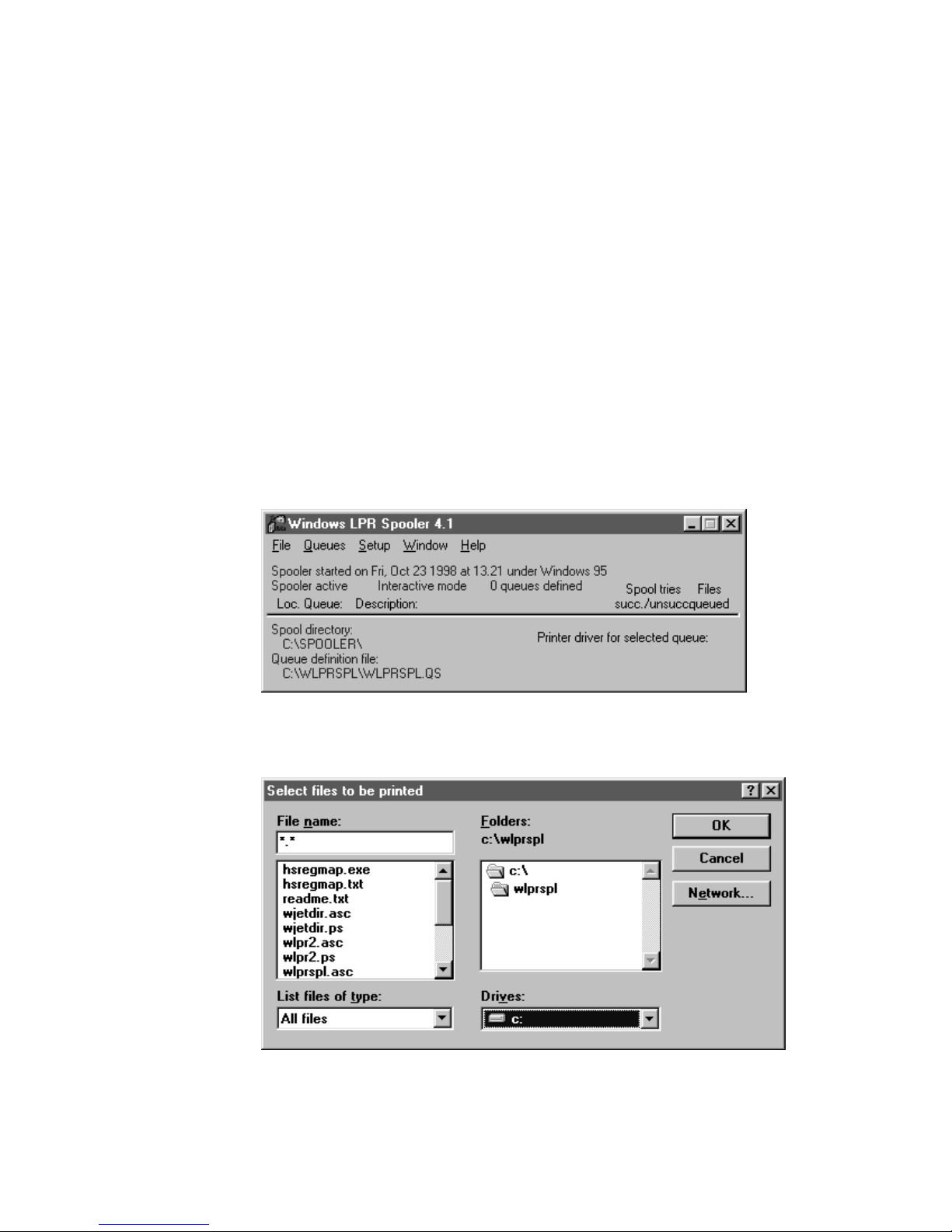
2. Click Start and select Programs then Windows LPR Spooler. The Windows LPR
Spooler window opens.
2-14
3. From the File menu, select Print file(s).
4. Under Drives, select the drive for the disks or CD-ROM.
Page 41

code39 code39 Connecting the Ethernet Adapter
5. Open the Intermec folder and select test_lbl.
6. Click OK.
7. Select the printer you want to print to and click OK.
To print the test label using an FTP session
1. Insert the disks or CD-ROM that came with the Ethernet adapter into the
appropriate drive.
2. From an MS DOS prompt, login to the Ethernet adapter using the command
host_name
example npserver.
, where host_name is the name assigned to your Ethernet adapter, for
2
ftp
3. Enter
4. Enter the following command to print the test label:
put a:\intermec\test_lbl pr1
Note:
5. Log out using the command
as user id and
root
Change
as password.
pass
to match the drive for the disks or CD-ROM.
a:
quit, bye
, or
depending on your FTP version.
exit
2-15
Page 42

Page 43

3
Setting Up the Ethernet Adapter for a
NetWare Network
Page 44

Page 45

code9 code9 Setting Up the Ethernet Adapter for a NetWare Network
This chapter explains how to install, configure, and manage your Ethernet adapter in
a NetWare network.
Setting Up Your Ethernet Adapter Using NDPS
The Ethernet adapter supports Novell Distributed Print Services (NDPS), which is
Novell’s new generation protocol for printer administration and printing.
Before you can install the Ethernet adapter, you must install NDPS and an HP Gateway
on your NetWare file server. The HP Gateway is included with the NDPS software and
is automatically installed together with NDPS. The Ethernet adapter uses the HP
Gateway when communicating with an NDPS printer.
You can disable the NDPS feature by setting the HP_JETADMIN parameter to NO.
Please refer to the appropriate Novell and Hewlett Packard documentation for further
details about NDPS and the HP Gateway.
To run NDPS, you must have NetWare version 4.11 or higher.
Note:
3
To install the connected printers as public access printers
1. Make sure that the HP Gateway is configured to automatically create a public
access printer before you connect the Ethernet adapter to the network.
2. Connect the Ethernet adapter to the NetWare network.
As soon as the HP Gateway finds the Ethernet adapter, it automatically creates a public
access printer. Any user may have access to the public access printer, which is found
with the Novell Printer Manager.
To install the connected printers as controlled access printers
1. Make sure that the HP Gateway is not configured to automatically create a public
access printer before you connect the Ethernet adapter to the network.
2. Connect the Ethernet adapter to the NetWare network.
3. Use the NetWare Administrator to create an NDPS printer as an object in the
directory. As directory objects, access to the printers is controlled and they are no
longer available as public access printers.
The controlled access printer is found in the Novell Printer Manager’s NDS object list.
3-3
Page 46

Intermec Ethernet Adapter User’s Manual code39 code39
Printing Methods
The following overview explains the advantages and limitations of the two supported
NetWare printing methods.
Print Server Mode
The Ethernet adapter logs into a file server(s) and repeatedly polls the print queues for
print jobs. In this fashion, the Ethernet adapter emulates a NetWare print server, which
is a workstation running PSERVER. It provides high printing speed with low network
load and is the recommended mode for medium to large networks. Each adapter in
PSERVER mode occupies one NetWare license.
Advantages Print server mode has high performance (typically 150 to 400K per
second).
Limitations Print server mode requires a NetWare user license for each Ethernet
adapter to file server link.
Remote Printer Mode
The Ethernet adapter connects itself to a PSERVER NetWare program running on the
file server or to a dedicated workstation running PSERVER.EXE. It then automatically
receives print jobs from the file server. In this fashion, the Ethernet adapter emulates a
workstation running the NetWare remote printer software RPRINTER or NPRINTER.
This mode is only recommended for small networks where the number of NetWare user
licenses is a major issue.
Advantages Remote printer mode does not require NetWare user licenses.
Limitations Remote printer mode has lower performance (typically 20 to 70K per
second for NetWare Loadable Module [NLM]) and causes higher network load.
Advanced Installation Using AXIS NetPilot
Having installed your Ethernet adapter, your Ethernet adapter now appears in the
contents of the Network Print Servers folder located in the AXIS NetPilot main
window. Use the NetWare Network Environment window to connect or create
additional print queues to your Ethernet adapter.
To access the NetWare Network Environment window
1. Select the required Ethernet adapter from the Network Print Server folder.
2. Choose Network from the Setup menu or click on the Network Icon on the toolbar.
3. If you are not already logged on to your NetWare file server, a dialog box will
prompt you to do so.
3-4
Page 47

NetWare Network Environment Window
For NetWare version 3.X, the Ethernet adapter periodically updates the configuration
by searching the NDS tree or the file servers in the case.
Setting Up the Ethernet Adapter for a NetWare Network
3
To connect a print queue
1. Select the adapter port you want to connect from the NetWare Network
Environment window.
2. Click the Connect button. The Connect NetWare Print Queues window appears.
3-5
Page 48

Intermec Ethernet Adapter User’s Manual
3. Select the location of the print queue from the Resources box.
4. Select an existing NetWare print queue for connection to the server port then go to
Step 7. If you want to create a print queue, click Create Queue and go to Step 5.
5. Type the queue name in the Create Queue dialog window. If you want to create a
queue in the NDS tree, type the name of the volume where you want to store the
queue. Click OK.
6. Select the newly created queue from the queue list.
7. Define the method of printing by selecting Print Server Mode or Remote Printer
Mode. If you selected Print Server mode, go to Step 10; otherwise, go to Step 8.
8. Select an appropriate NetWare Print Server name that will work with the Ethernet
adapter by using the Browse button. You cannot type or edit the name manually.
9. If you want to define a remote printer number slot manually, check the Manual box
and type the desired number in the box.
10. Click the OK button to return to the Network Environments window.
3-6
Page 49

4
Setting Up the Ethernet Adapter for a
Windows Network
Page 50

Page 51

Setting Up the Ethernet Adapter for a Windows Network
This chapter describes how to use the AXIS Print Utilities for printing in the Windows
environment.
4
Using the AXIS Print Monitor for Windows 95, 98, and NT
The AXIS Print Monitor is supplied on the CD-ROM or disks that are provided with
your Ethernet adapter. You use the AXIS Print Monitor software for network printing
within Windows 95, 98, and NT environments. It allows the Ethernet adapters to be
connected in the same simple fashion as a local printer port and, once installed, to be
automatically initialized upon system startup.
Install the AXIS Print Monitor now if you have not already done so. For help, see
“Installing AXIS Print Utilities” in Chapter 2.
To change the default name or amend any of the Ethernet adapter default parameters,
use the AXIS NetPilot or any standard Web browser. For help, see Chapter 8,
“Managing and Configuring the Ethernet Adapter.”
About the AXIS Print Monitor
AXIS Print Monitor is a Windows component developed for peer-to-peer printing under
Windows 95, 98, and NT. It allows you to send print jobs directly to the Ethernet
adapter.
You can use the AXIS Print Monitor for DOS printing when installed on
Note:
Windows NT platforms. However, in Windows 95 or 98, DOS printing is only possible
from a client workstation in a client/server configuration. If DOS peer-to-peer printing
is necessary from a Windows 95 or 98 platform, use the AXIS Print Utility for
Windows.
Printing Environments
The AXIS Print Monitor supports printing over NetBIOS/NetBEUI and TCP/IP (LPR).
To enable printing in any of the environments, ensure that the desired protocol is
running on your client.
Peer-to-Peer Printing
Install the AXIS Print Monitor on each workstation performing peer-to-peer printing.
Once installed, the AXIS Print Monitor then allows you to access all network printers,
just as if the printers were connected directly to your workstation. Peer-to-peer printing
has the following benefits:
• You can easily monitor the status of your printers by enabling error condition
pop-up messages.
• You do not have to rely on a server.
4-3
Page 52

Intermec Ethernet Adapter User’s Manual
Client/Server Printing
Do not enable pop-up messages on the server as the status of shared printers will not be
reported to the client platforms. Pop-up messages are only issued on the server.
User Dialog
Although the AXIS Print Monitor user dialog varies depending on the platform you are
using (Windows 95, Windows 98, Windows NT 4.0, or Windows NT 3.5X), the
functionality is exactly the same.
Note: Use the printer driver provided with the printer even if the desired printer is
available from the manufacturer and model lists. Using the driver provided with your
printer ensures that you are using the latest software.
Using the AXIS Print Monitor With Windows 95 or 98
Follow the next procedures to install printer ports from a Windows 95 or 98
workstation.
To install printer ports with NetBIOS or NetBEUI
1. To start the Add Printer Wizard, select Settings then Printers from the Start Menu
and double-click the Add Printer icon.
2. After clicking Next in the first dialog box, select Local Printer because the Ethernet
adapter emulates a local printer port. Click Next.
3. Choose the appropriate printer driver for your printer. If the desired printer driver
appears within the displayed manufacturer and model lists dialog box, highlight
your selection, click Next, and go to Step 6. If your printer is not in the model list,
go to Step 4.
4. Click the Have Disk button. Insert the CD-ROM or disks provided with your
adapter, select the appropriate drive, and click OK.
5. Select the printer driver and click Next.
6. Select an AXIS Printer Port from the Available Ports list. The port name appears as
name.LP1, where name is AX followed by the last six digits of the Ethernet
adapter’s serial number, for example AX100086. Click the Configure Port button.
7. Check the pop-up message box in the Configure AXIS Printer Ports dialog box to
have error condition pop-up messages appear. Define the frequency at which the
error messages appear after retry. Click Next.
8. Enter an appropriate name for your printer and click Next.
9. Click Finish.
4-4
Page 53

Setting Up the Ethernet Adapter for a Windows Network
To install printer ports with TCP/IP
To be able to print using LPR, you must install the Ethernet adapter in the
Note:
TCP/IP environment. For help, see “Setting Up for TCP/IP” in Chapter 2.
1. To start the Add Printer Wizard, select Settings then Printers from the Start Menu
and double-click the Add Printer icon.
2. After clicking Next in the first dialog box, select Local Printer as the Ethernet
adapter emulates a local printer port. Click Next.
3. Choose the appropriate printer driver for your printer. If the desired printer driver
already appears within the displayed manufacturer and model lists dialog box,
highlight your selection, click Next, and go to Step 6. If your printer is not in the
model list, go to Step 4.
4. Click the Have Disk button. Insert the CD-ROM or disks provided with your
adapter, select the appropriate drive, and click OK.
5. Select the printer driver and click Next.
6. Select an AXIS LPR Port and then click OK. Available LPR ports appear as
port_name@internet_address or port_name@host_name, for example
PR1@192.36.254.101. To install a new LPR port, select the Printers@LPR port.
Click the Configure Port button.
4
7. Check the pop-up messages box in the Configure AXIS LPR Ports dialog box to
have error condition pop-up messages appear. Define the frequency at which the
error messages appear after retry. Click OK then Next.
The dummy port cannot be used for printing and consequently cannot be
Note:
configured.
8. Enter an appropriate name for your printer and click Next.
9. Click Finish.
Continue with the following steps only if you want to install a printer to a new LPR
port and have chosen Printers@LPR port in Step 6.
10. The printer you have defined appears in the Printers Folder. Right-click the printer
object and select Properties from the Context menu.
11. Click the details tab within the Properties page and then click Add Port to display
the available monitors.
12. Click the radio button “other.” Select AXIS Port and then click OK.
13. Select LPR (TCP/IP) as your choice of network protocol and click OK.
14. Enter the IP address or the host name of your adapter and assign an appropriate
Logical Printer. Click OK.
15. The LPR port appears in the list of available ports. Click OK.
4-5
Page 54

Intermec Ethernet Adapter User’s Manual
16. Configure the port as described in Step 7.
17. Click the Apply button.
The Ethernet adapter printer port is now installed.
Using the AXIS Print Monitor With Windows NT 4.0
Follow the next procedure to install Axis Printer Ports from a Windows NT 4.0
workstation.
To install printer ports with NetBIOS or NetBEUI
1. To start the Add Printer Wizard, select Settings then Printers from the Start menu
and double-click on the Add Printer icon.
2. Select My Computer, as the Ethernet adapter emulates a local printer port.
3. Click Add Port in the Available ports dialog box, select AXIS Port and click New
Port.
4. Select the AXIS Port you want to add. The port appears as name.LP1, where name
is AX followed by the last six digits of the Ethernet adapter’s serial number, for
example AX100086. Click OK.
5. Close the Printer Ports window.
6. Click the Configure Port button. Check the pop-up messages box in the Configure
AXIS LPR Ports dialog box to have error condition pop-up messages appear.
Define the frequency at which the error messages appear after retry. Click OK then
Next.
7. Choose the appropriate printer driver for your printer. Click Next and go to Step 10.
Go to Step 8 if your printer does not feature within the model list.
8. Click the Have Disk button. Insert the CD-ROM or disks provided with your
adapter, select the appropriate drive, and click OK.
9. Select the printer driver and click Next.
10. Enter an appropriate name for your printer and click Next.
11. Choose whether you want to share the printer with other network users and click
Next.
12. Click Finish.
4-6
Page 55

Setting Up the Ethernet Adapter for a Windows Network
To install printer ports with TCP/IP
To be able to print using LPR, you must install the Ethernet adapter in the
Note:
TCP/IP environment. For help, see “Setting Up for TCP/IP” in Chapter 2.
1. To start the Add Printer Wizard, select Settings then Printers from the Start menu
and double-click on the Add Printer icon.
2. Select My Computer because the Ethernet adapter emulates a local printer port.
Click Next.
3. If the LPR Printer port you want to use already appears in the available ports list,
go to Step 8. If not, click Add Port and continue with Step 4.
4. Select AXIS port from the list of available monitors in the Printer Port dialog box.
Click the New Port button.
5. Select LPR (TCP/IP) as your choice of network protocol and click OK.
6. From the Add AXIS LPR Port dialog box, enter the IP address or host name of your
adapter and define a Logical printer name. Click OK.
7. Click OK to return to the Printer Ports dialog box. Click Close.
4
8. Select an AXIS LPR Port you want to use and then click OK. Available LPR ports
appear as port_name@internet_address or port_name@host_name, for example
PR1@192.36.254.101.
9. Click Configure Port. Check the pop-up messages box in the Configure AXIS LPR
Ports dialog box to have error condition pop-up messages appear. Define the
frequency at which the error messages appear after retry. Click OK.
10. Having selected and configured the chosen port, click Next.
11. Choose an appropriate printer driver for your printer. If the desired printer driver
already appears within the displayed manufacturer and model lists dialog box,
highlight your selection, click Next, and go to Step 14. Go to Step 12 if your printer
does not feature within the models list.
12. Click the Have Disk button. Insert the CD-ROM or disks provided with your
adapter, select the appropriate drive, and click OK.
13. Select the printer driver and click Next.
14. Enter an appropriate name for your printer and click Next.
15. Choose whether you want to share the printer with other network users and click
Next.
16. Click Finish.
4-7
Page 56

Intermec Ethernet Adapter User’s Manual
Using the AXIS Print Monitor With Windows NT 3.5X
Follow the next procedure to install Axis printer ports from a Windows NT 3.5X
workstation.
To install printer ports with NetBIOS or NetBEUI
1. Open the Print Manager and select Create Printer from the Printer Menu.
2. Enter an appropriate name in the Printer Name field.
3. Choose an appropriate printer driver for your printer from the manufacturer and
model lists displayed and then go to Step 6. Go to Step 4 if your printer does not
feature within the model list.
4. Select Other in the driver list. Insert the CD-ROM or disks provided with your
adapter, select the appropriate drive, and click OK.
5. Select the printer driver.
6. Select Other in the “Print to” list box.
7. Select Axis Port in the list of available Print Monitors and click OK.
8. Select the port you want to add and then click OK. The port appears as name.LP1,
where name is AX followed by the last six digits of the Ethernet adapter’s serial
number, for example AX100086.
9. Click on Settings. Check the pop-up messages box in the Configure AXIS LPR
Ports dialog box to have error condition pop-up messages appear. Click OK.
10. Click OK.
To install printer ports with TCP/IP
Note: To be able to print using LPR, you must install the Ethernet adapter in the
TCP/IP environment. For help, see “Setting Up for TCP/IP” in Chapter 2.
1. Open the Print Manager and select Create Printer from the Printer Menu.
2. Enter an appropriate name in the Printer Name field.
3. Choose an appropriate printer driver for your printer from the drop-down Driver
list. If the desired printer driver already appears in the displayed manufacturer and
model lists dialog box, go to Step 6. Go to Step 4 if your printer does not appear in
the model list.
4. Select Other in the driver list. Insert the CD-ROM or disks provided with your
adapter, select the drive, and click OK.
5. Select the printer driver you want to install.
6. Select Other from the “Print to” drop-down list.
4-8
Page 57

Setting Up the Ethernet Adapter for a Windows Network
7. Select AXIS Port from the list of available Print Monitors in the Print Destination
dialog box. Click OK.
8. Select LPR (TCP/IP) as your choice of network protocol and click OK.
9. From the Add LPR port dialog box, enter the IP address or host name of your
adapter and define a Logical printer name. Click OK to return to the Create Printer
dialog box.
10. Select the LPR port you want to use from the “Print to” drop-down list. The ports
appear as port_name@internet_address or port_name@host_name, for example
PR1@192.36.254.101.
11. Click the Settings button. Check the pop-up messages box in the Configure AXIS
LPR Ports dialog box to have error condition pop-up messages appear. Define the
frequency at which the error messages appear after retry. Click OK to return to the
Create Printer dialog box.
12. Having selected and configured the chosen port, click Next.
13. Select whether you want to share the printer with other network users. Click OK.
The printer properties are displayed within an appropriate dialog box that allows you to
refine your printer setup.
4
The Axis printer is now installed and will appear as an icon within the Print Manager.
Using the Microsoft LPD Monitor for Windows NT
This section provides instructions for setting up your Ethernet adapter for line printer
(LPR) or line printer daemon (LPD) printing over the TCP/IP protocol using the builtin Microsoft LPD monitor.
If you have not already done so, you should perform the TCP/IP basic setup procedures
prior to installing a printer for LPD printing. For help, see “Setting Up for TCP/IP” in
Chapter 2.
To see if TCP/IP is already installed, click the Network icon in the Control Panel. If the
TCP/IP Printing entry appears, then TCP/IP is already installed. Close the Network
folder and go to the procedure to install a printer later in this section. If the TCP/IP
Printing entry does not appear, go to the Windows NT 4.0 procedure to prepare for
LPR/LPD printing or to the Windows NT 4.0 procedure to install the TCP/IP protocol
stack.
4-9
Page 58

Intermec Ethernet Adapter User’s Manual
Using the Microsoft LPD Monitor With Windows NT 4.0
This section describes how to set up Windows NT Server version 4.0 for LPR printing.
To prepare for LPR/LPD printing
1. Open the Control Panel and click the Network icon.
2. Select Protocols.
3. Add TCP/IP Protocol.
4. Select Services.
5. Add MS TCP/IP Printing.
To install a printer for LPD printing
1. Open the Control Panel and open the Printers folder.
2. Click Add Printer, select My Computer and then go to Next.
3. Select Add Port. In Printer Ports, choose LPR Port and then click New Port.
4. In Add LPR compatible printer, enter the name or IP address of the Ethernet
adapter as the print server to provide LPD.
5. Enter “pr1,” “pr2,” … “pr8” as the name of the printer or the print queue on that
server.
6. Choose a suitable printer driver for your printer and go to Next.
7. Enter a printer name and go to Next.
8. Select Shared to share the printer over the network.
9. Enter a share name.
10. Click Next and then Finish.
To use a shared printer from a Windows 95 or 98 client
1. Open the Control Panel.
2. Open the Printers folder.
3. Click Add Printer.
4. Select Network Print Server and then go to Next.
5. Enter the path for the network printer or browse the network to find and select it.
6. Go to Next and then Finish.
4-10
Page 59

Setting Up the Ethernet Adapter for a Windows Network
4
Using the Microsoft LPD Monitor With Windows NT 3.5X
This section describes how to set up Windows NT Server versions 3.5 and 3.51 for
LPD printing.
To install the TCP/IP protocol stack
1. In the Control Panel, select Network.
2. Click Add Software.
3. Select “TCP/IP Protocol and related components” and then click Continue.
4. Check “TCP/IP Network Printing Support” and then click Continue.
5. Select path and then click Continue.
6. Click OK in the Network Settings dialog box.
To install a printer for LPD printing
1. In the Control Panel, click the Print Manager.
2. In the Printer menu, select Create Printer.
3. In the Printer Name field, type a name for your printer.
4. Choose a suitable printer driver for your printer.
5. In the Print to field, select Other.
6. In the Print Destinations dialog box, choose LPR Port and then click OK. The Add
LPR Compatible Printer dialog box appears.
7. In the Name or Address field, type the IP address or the alias name of your Ethernet
adapter. The alias name must be defined in the hosts file on your server. The hosts
file is normally located in /winnt35/system32/drivers/etc/hosts.
8. In the Name of Printer on the Machine field, type the logical printer number you
want to use, such as pr1. Click OK.
9. Click OK to complete the installation.
4-11
Page 60

Intermec Ethernet Adapter User’s Manual
Setting Up the Ethernet Adapter to Use an LPR Spooler
If you are using an LPR spooler to print via TCP/IP, follow the next instructions to
install your Ethernet adapter with the LPR spooler. For help installing the LPR spooler,
see “Installing the LPR Spooler” in Chapter 2.
To use an LPR spooler for Windows 3.1 and Windows for Workgroups
1. Start Control panel.
2. Click Printers.
3. Install a printer driver.
4. Click Connect.
5. Choose your queue. For example:
C:\spooler\myprinter
To use an LPR spooler for Windows 95 or 98
1. From the Start menu, click Settings then Printers.
2. Double-click Add Printer. The Add Printer Wizard window appears.
3. Click Next.
4. Select Local Printer and click Next.
5. Select your printer and click Next.
6. Select your queue. For example:
C:\spooler\myprinter
Using the AXIS Print Utility for Windows
The AXIS Print Utility for Windows is supplied on the CD-ROM or disks that came
with your Ethernet adapter and is the tool for network printing within Windows for
Workgroups and Windows 3.1 environments.
You should install this utility now if you have not already done so. For help, see
“Installing AXIS Print Utilities” in Chapter 2.
4-12
Page 61

Setting Up the Ethernet Adapter for a Windows Network
4
About AXIS Print Utility for Windows
AXIS Print Utility for Windows is a dual purpose application for network printing in
the Windows environment. It has two fundamental purposes:
• Install and maintain Ethernet adapter printer ports as Windows printer ports.
• Capture and monitor print jobs directed to the Ethernet adapter ports. Print jobs are
directed through a spool directory either at your local hard disk (peer-to-peer mode)
or at the file server (client/server mode). The printer port status of your Ethernet
adapter may be monitored and pop-up notification messages can be generated,
keeping you informed of completed print jobs or any problematic condition.
For more information about AXIS Print Utility for Windows, see the online help.
To use AXIS Print Utility for Windows, Microsoft Network (NetBIOS/NetBEUI) must
be running.
To print in peer-to-peer mode, AXIS Print Utility for Windows must be running. The
AXIS Print Utility for Windows is not needed on the client platforms for client/server
printing.
If you want to change the default name of your Ethernet adapter or amend any of
Note:
the default parameters, you may do so using the AXIS NetPilot or any standard Web
browser. For help, see Chapter 8, “Managing and Configuring the Ethernet Adapter.”
Peer-to-Peer vs. Client/Server Printing
Windows for Workgroups and Windows 3.1 users requiring access to a network printer
in Peer-to-Peer mode need to install the AXIS Print Utility for Windows software on
their workstations. Users may then add the required network printer to their systems
and use the printer as if it was connected directly to their workstation. Peer-to-peer
printing affords the following benefits:
• You can monitor the printer status at all times and be notified when a print job is
complete.
• You do not have to rely on a server.
Client/server operation requires only one user to install the AXIS Print Utility for
Windows software onto their workstation. This user then adds the printer to his or her
workstation (the server) and shares the printer with other users on the network. The
other users (the clients) may connect to the printer through the server via the Windows
Print Manager.
Client/server mode provides a way of maintaining queue ordering and job priority, but
at a price:
• You cannot receive printer status or print job notification.
• The workstation set up as the server must be available at all times. It must also have
the capacity to handle the print jobs that pass through it.
4-13
Page 62

Intermec Ethernet Adapter User’s Manual
Note: When using Client/Server mode, other users may still install the AXIS Print
Utility for Windows software to print in Peer-to-Peer mode. When using Client/Server
mode, it is recommended that you set up the server only on a Windows for Workgroups
workstation.
Note: AXIS Print Utility for Windows must be running when you print through your
Ethernet adapter. We strongly recommend that you copy the AXIS Print Utility icon
into your StartUp folder.
To use peer-to-peer printing
Note: In order to print to a network printer, Windows 3.1 requires the installation of
network support, such as the LAN Server or LAN Manager Workstation software.
1. Double-click the AXIS Print Utility icon.
2. In the Port menu, click Add.
3. In the NPS Port list, select the Ethernet adapter port. The port appears as name.LP1,
where name is AX followed by the last six digits of the Ethernet adapter’s serial
number, for example AX100086. However, you can change the name using AXIS
NetPilot.
4. Accept or change the suggested Windows port name and type any required
comment in the Description field. Make a note of the Windows port name as you
will need this later, then click OK to install the Windows port.
5. In the Port menu, click Connect to bring up the Windows Printers dialog box.
6. Select a printer driver from the list of Installed Printers (or click Add to install a
new driver), then click Connect.
7. Select the Windows port name from Step 4 (this name can be found at the bottom
of the Ports list).
8. Click OK to close the Connect dialog box and Close to close Printers.
The setup is completed and you can now print through your Ethernet adapter.
4-14
Page 63

Setting Up the Ethernet Adapter for a Windows Network
To set up the server for client/server printing
In order to print to a network printer, Windows 3.1 requires the installation of
Note:
network support, such as the LAN Server or LAN Manager Workstation software.
1. Choose a workstation that you want to use as a server for network printing. The
server must be available at all times and must have sufficient hard disk space for
spooling print jobs.
2. Make sure that the printer sharing option is enabled. (Open Network Setup, click
Sharing; check the “I want to be able to allow others to print to my printer(s)” box).
3. Install AXIS Print Utility for Windows on the server.
4. Set up your Ethernet adapter as described in the previous procedure.
5. Open Print Manager and select your printer.
6. In the Printer menu, select Share Printer As.
7. Type a printer name in the Share As field (this is the printer name seen by the
clients).
8. Check the Re-share at Startup box, then click OK.
4
The server setup is now complete. Set up the clients as described below.
To set up the clients for client/server printing
In order to print to a network printer, Windows 3.1 requires the installation of
Note:
network support, such as the LAN Server or LAN Manager Workstation software.
1. In the Control Panel, select Printers.
2. Select a printer driver from the list of Installed Printers, or click Add to install a
new driver. Click Connect.
3. Select Network in the Device Name list and select a local port (LPT1 to LPT3) to
redirect to your network printer.
4. In the Show Shared Printers on list, select the server from Server Setup above.
5. In the Shared Printers list, select the printer you want to use.
6. Click OK; click OK, then click Close.
7. Exit the Control Panel.
The client setup is completed and you can now print through your Ethernet adapter.
4-15
Page 64

Intermec Ethernet Adapter User’s Manual
Windows Clients Using LANtastic
From any Windows client, the Ethernet adapter may also be used for network printing
within LANtastic environments.
LANtastic users may use the AXIS utilities in exactly the same manner as described in
the preceding Windows sections, using a choice of Axis utility software that is guided
by the type of Windows client employed:
• Refer to “Using the AXIS Print Utility for Windows” earlier in this chapter if you
are using a Windows for Workgroups client.
• Refer to “Using the AXIS Print Monitor for Windows 95, 98, and NT” earlier in
this chapter if you are using either a Windows 95, 98, or NT client.
Make sure that your LANtastic client is running the desired printing protocols.
4-16
Page 65

5
Setting Up the Ethernet Adapter for an
OS/2 Network
Page 66

Page 67

Setting Up the Ethernet Adapter for an OS/2 Network
This chapter describes how to set up your Ethernet adapter for printing in the OS/2
environment.
Using the AXIS Print Utility for OS/2
The installation and setup operations are performed with the AXIS Print Utility for
OS/2. You should install this utility now if you have not already done so. For help, see
“Installing AXIS Print Utilities” in Chapter 2.
You can change the default name of your Ethernet adapter or amend any of the default
parameters by using any standard Web browser or AXIS NetPilot from any Windows
platform that is connected to your network or WinOS/2 window under OS/2. For help,
see Chapter 8, “Managing and Configuring the Ethernet Adapter.”
You do not need the AXIS Print Utility for OS/2 on the client platforms when using a
client/server configuration.
AXIS Print Utility for OS/2 is a dual purpose application for network printing in the
OS/2 environment. Its fundamental purpose is to:
• Install and maintain the Ethernet adapter printer port as an OS/2 printer port.
5
• Capture and monitor print jobs directed to the Ethernet adapter port. Print jobs may
be directed through a spool directory either at your local hard disk or at the file
server. You can monitor the printer port status of your Ethernet adapter and pop-up
notification messages can inform you of completed print jobs or any problematic
condition.
The NetBEUI protocol must be active. If this protocol is not active, use MPTS/LAPS
(LAN Server) or SETUP (LAN Manager) to activate it.
If you are using OS/2 version 2.X and want to print through TCP/IP, we
Note:
recommend that you use the IBM TCP/IP for OS/2 product. It supports the LPD and
interactive FTP print methods.
To install the Ethernet adapter
1. When AXIS Print Utility for OS/2 is running, click Install to install your Ethernet
adapter. The port appears in the list as name.LP1, where name is AX followed by
the last six digits of your adapter number, for example AX100086.LP1. However,
you can change this name using AXIS NetPilot.
2. Select the port that you want to install, then click Install.
3. Repeat this procedure for each server using the Ethernet adapter.
Note: The AXIS Print Utility for OS/2 must be running in order to print using your
Ethernet adapter.
5-3
Page 68

Intermec Ethernet Adapter User’s Manual
Integrating Your Ethernet Adapter Into the OS/2
Environment
To use your Ethernet adapter on an OS/2 network, you have to create a print queue for
the printer and adapter. After you have created the print queue, you can make the print
queue a shared resource so that other OS/2 clients can use the same printer.
Creating a Print Queue
To create a print queue with OS/2 version 1.X
1. Double-click the Print Manager icon, click Setup, then select Printers.
2. Click Add to make a new printer definition, then type a name of your choice in the
Name field.
3. Select \PIPE\name.LP1 from the Device list, then select a printer driver suitable for
your printer.
4. Click Add, then click OK to confirm the printer definition.
5. Click Setup, then select Queues.
6. Click Add to create a print queue, and type a name in the Name field.
7. Click Add, then click OK to confirm the queue definition.
To create a print queue with OS/2 version 2.X and OS/2 Warp
1. Double-click the Templates folder, then drag the Printer icon out to the Workplace
Shell (or into a folder) while holding the right mouse button down.
2. Type a name of your choice in the Name field.
3. Select \PIPE\name.LP1 from the Port list, and select a printer driver suitable for
your printer from the Standard Printer list.
4. Click OK to confirm the printer definition.
Sharing the Print Queue
A print queue must be made a shared resource before it can be accessed from other
computers (clients or other servers).
Open an OS/2 window and issue the following command:
NET SHARE
5-4
queue_name
/PRINT
Page 69

Setting Up the Ethernet Adapter for an OS/2 Network
where:
queue_name is the name of the queue created.
To share a printer resource when using OS/2 Warp with IBM Peer service
1. Click the right mouse button on the printer object.
2. Select Share and then Start sharing. In the dialogue box, enter a Description.
3. Select the check-box Start sharing at LAN workstation start-up.
4. Click OK.
The setup is completed and you can now print through your Ethernet adapter.
To share a printer resource when using LAN server 4.0
1. Open LAN Server Administration.
2. Open your domain and then Resource Definition.
3. Drag and drop a printer from the template.
5
4. Enter the Alias name, then select a Server name and the previously created Spooler
Queue Name.
5. Click OK.
The setup is completed and you can now print through your Ethernet adapter.
5-5
Page 70

Page 71

6
Setting Up the Ethernet Adapter for a
Macintosh Network
Page 72

Page 73

Setting Up the Ethernet Adapter for a Macintosh Network
This chapter describes how to set up your Ethernet adapter for printing in the
AppleTalk environment.
Installing Using the Chooser Window
To perform the basic configuration in the Apple EtherTalk environment, open the
Chooser window and select a printer. You need to create your own printer driver or
network compatible application to work with Intermec printers.
You can change the default name of your Ethernet adapter or amend any of the default
parameters. However, to access the configuration file from a Macintosh, you need FTP
support such as MacTCP, Fetch, or Anarchie.
Communications Support and Protocols
The Ethernet adapter allows your printer driver to communicate directly with the
printer and consequently facilitates complete functional control over print jobs, such as
automatic downloading of fonts not resident in the printer.
6
This functionality has backward compatibility with older Macintosh computers, which
means that the Ethernet adapter can generate appropriate responses to Macintosh
printer queries, when the connected printer does not support bi-directional
communication.
Binary communication protocol (BCP) and tagged binary communicationprotocol
(TBCP) are communication protocols used by the serial and parallel ports of a printer.
They allow 8-bit binary data in files concurrent with the use of some control characters
for communication and print job control. TBCP is required for printing with a binary
data stream on some printers, such as HP printers.
Setting Parameters
From within the Macintosh environment, you can set a small number of the parameters
of the Ethernet adapter. You can select ASCII or either of the binary data protocols for
your printing and you can set the IP address, which enables you to configure and
manage your Ethernet adapter from any standard Web browser.
To set parameters
1. Open the Chooser.
2. Select a network printer driver.
3. Select the printer port that ends with “_CFG.”
4. Close the Chooser.
5. Open a text editor such as SimpleText.
6-3
Page 74

Intermec Ethernet Adapter User’s Manual
6. Write a text file containing the following:
BINARY : YES
BINARY_TYPE : TBCP
INT_ADDR : 192.168.3.191
The BINARY parameter can take the values YES or NO. The BINARY_TYPE
parameter can take the values BCP or TBCP. See the technical reference for more
information on these parameters.
Note: Do not use the IP address in the example above. Always consult your
Network Administrator before assigning an IP address.
7. Print the above text file. The adapter permanently stores the settings.
8. Open the Chooser and select the printer port you want to use for printing
documents.
9. Finish the process by closing the Chooser.
6-4
Page 75

7
Setting Up the Ethernet Adapter for a
UNIX Network
Page 76

Page 77

Setting Up the Ethernet Adapter for a UNIX Network
This chapter explains how to use axinstall to configure your Ethernet adapter.
Integrating Into the Host Printer Spooler
Having performed the basic TCP/IP setup procedures in Chapter 2, you are now able to
print in interactive mode using LPR (LPD), FTP, or Reverse Telnet protocols.
However, if you need to integrate the Ethernet adapter into your host spooler, you can
use the Axis automatic installation script axinstall. This utility software is resident on
the Ethernet adapter, but it can also be uploaded to your host using FTP, so no disks are
required. The axinstall script is also available on the CD-ROM or disks that came with
your adapter. Having completed this operation, the printer connected to the Ethernet
adapter will appear as though they are directly connected to the host printer spooler.
To install the installation script axinstall using FTP
7
1. Login to the Ethernet adapter using the command
host_name is the name assigned to your Ethernet adapter, for example npserver.
as user id and
2. Enter
3. Download the script using the command
4. Log out using the command
The following is a typical FTP session for collecting the axinstall script.
> ftp npserver
connected to npserver.
220 AXIS 540/640 FTP Print Server v5.51 Apr 17 1998 ready.
Name (npsserver:thomas): root
331 User name ok, need password
Password: pass (not visible)
230 User logged in
ftp> get axinstall
200 PORT command successful.
150 Opening data connection for axinstall (192,36,253,4,13,223),
(mode ascii).
226 Transfer complete.
local: axinstall remote: axinstall
61187 bytes received in 14 seconds (4.2 kbytes/s)
ftp> bye
221 Goodbye.
>
root
below.
as password.
pass
quit, bye
get axinstall
, or
exit
ftp
host_name
as shown in the example
depending on your FTP version.
, where
7-3
Page 78

Intermec Ethernet Adapter User’s Manual
The axinstall script has now been downloaded to your host. Execute the script with this
command:
sh axinstall
Follow the step-by-step procedure through the installation. During the installation you
will be asked to select a print method; we suggest you choose LPD or, for more
functionality, use the PROS filter or named pipe methods. Please refer to the following
pages if you need guidance on the choice of print methods.
The axinstall script will suggest one of the systems listed when started. If you do not
find the suggestion appropriate, then manually select any of the systems listed next:
• SunOS 4 (SUN BSD, Solaris 1.X)
• SunOS 5 (SUN SYS V, Solaris 2.X)
• AIX (IBM RS/6000, BULL DPX 20)
• HP
-UX (HP 9000)
• BOS (BULL DPX 2)
• DEC
OSF/1 (Digital Equipment, Alpha)
• ULTRIX (Digital Equipment, DEC)
• IRIX (Silicon Graphics, SGI)
• SCO
UNIX (Santa Cruz Operation)
• FreeBSD (Berkeley UNIX)
• Generic BSD (Berkeley UNIX)
• Generic SYS V R3 (UNIX System V Release 3)
• Generic SYS V R4 (UNIX System V Release 4)
Print Methods on TCP/IP Networks
The Ethernet adapter supports several different print methods in the TCP/IP
environment. The utility axinstall will suggest a print method suitable for your
particular UNIX system, but you might want to use another method depending on your
printing requirements.
The next diagram shows the alternative data paths taken by some of the UNIX print
methods. This illustrates some of the advantages and limitations of the different
methods. Use the following information to determine which method to adopt.
7-4
Page 79

Data Paths Taken by UNIX Print Methods
File to
print
DIRECT
FTP
RTELNET
Print
spooler
Printer
Setting Up the Ethernet Adapter for a UNIX Network
Directly
connected
printer
AXISI.007
Filter/
interface
model
LPD
RTELNET
Ethernet adapter
FTP
PROS B
Parallel port
Named pipe
PROS print
daemon
PROS A
7
Line Printer Daemon
The line printer daemon (LPD) is a protocol for transferring print jobs between hosts.
This is the recommended method for UNIX systems, but some System V versions do
not support LPD.
Advantages LPD is easy to set up and install the Ethernet adapter as a remote queue
in System V or to add a remote printer to
/etc/printcap
using the rm and rp fields
(BSD).
Limitations Spooler features and
printcap
or
options (BSD), such as multiple
lpr
copies, are not available.
File Transfer Protocol
The file transfer protocol (FTP) is used for transferring files between hosts.
Advantages FTP uses industry standard network software on the host.
Limitations FTP does not provide printer status logging. In the case of BSD, it may
conflict with other input or output filters and does not allow both input and output
filters. In System V, you cannot use filters or interface programs.
PROS
PROS is a protocol developed at Axis. It comes in two versions named pipe (PROS A)
and filter (PROS B).
7-5
Page 80

Intermec Ethernet Adapter User’s Manual
PROS A
Advantages The Ethernet adapter appears as a device to the system. This makes all
filter and model options available. It provides accounting and status logging and
supports bi-directional printing. You can view the printer information read back in a log
file.
Limitations A ‘C’ compiler is required to build the PROS A drivers.
PROS B
Advantages It provides accounting and status logging and supports bi-directional
printing. You can view the printer information read back in a log file.
Limitations A ‘C’ compiler is required to build the PROS B drivers, and in the case of
BSD, it may conflict with other input or output filters. BSD does not allow both input
and output filters. You cannot use interface programs in System V.
Reverse Telnet
Reverse Telnet is often used for printing via a terminal server printer port and is only
recommended if you already have a Reverse Telnet driver installed.
Advantages Reverse Telnet is easy to set up with previously installed Reverse Telnet
drivers.
Limitations Reverse Telnet does not have status logging. Drivers are not supplied
with the Ethernet adapter. Existing drivers may be slow.
Other Systems
This section covers other UNIX and MVS systems you can use.
Other UNIX Systems
Most UNIX systems resemble either BSD or System V, so with some ingenuity a
solution can also be devised for other variants.
If the system has BSD socket type networking support, then
directory of the Ethernet adapter) can be used as a starting point. It receives print data
stdin
from
Alternatively, FTP may be used. You should use
a starting point.
and writes a log file to
stderr
. Nothing is written to
bsd/ftp_bsd
prosbsd
IBM MVS Systems
A sample JCL (job control language) script,
the Ethernet adapter. It gives an example of how to print a file from a multiple virtual
storage (MVS) mainframe to an Ethernet adapter using FTP.
, is available in the
jclex
(in the
stdout
or
sysv/ftp_sysv
.
directory of
mvs
bsd
as
7-6
Page 81

Setting Up the Ethernet Adapter for a UNIX Network
Customizing Your Printing
The Ethernet adapter can alter the print data to match the type of printer you are using,
so that you can use your desired print format on any type of printer. You can invoke the
following actions from the Ethernet adapter:
• You can change the character set to suit the printer.
• You can add strings before and after the print data.
• You can substitute strings within the print data.
• The Ethernet adapter can convert ASCII to PostScript
• If the printer is busy, the Ethernet adapter can redirect print data to another printer.
• You can use Hex Dump mode to assist with printing problems.
If any of these actions are required, a logical printer is used to change the print data
before being sent to the printer port. There are eight logical printers that can be set up
to filter the print data.
Edit the parameters in the Ethernet adapter’s configuration file to configure a logical
printer. For more information, see Appendix A, “Configuration Parameters.” The
default logical printers settings are such that PR1 through PR4 cause no change to the
flow of print data, while PR5 through PR8 add CR to LF control characters.
7
.
Logical Printer Changes to data
PR1 no change
PR2 no change
PR3 no change
PR4 no change
PR5 add CR to LF
PR6 add CR to LF
PR7 add CR to LF
PR8 add CR to LF
Converting Character Sets
A common problem in a multiple host environment is that different hosts use different
ASCII character sets. As a result, language-specific characters (such as å ü ô ñ) are
sometimes printed incorrectly.
To avoid this problem, the Ethernet adapter assigns a character set conversion filter to a
logical printer and then links that logical printer to the host causing the problem.
7-7
Page 82

Intermec Ethernet Adapter User’s Manual
You can choose from several different filters within the PR1_CSET Character Set
Conversion. For more information, see Appendix A, “Configuration Parameters.” The
output from the conversion filter is always IBM PC Set 2 (Code Page 437), which you
should set up on your printer.
The following text provides an example scenario:
Problem Your network contains three hosts using the character sets IBM PC Set 2,
ISO 8859-2, and DEC.
Solution In order for different hosts to direct their print jobs to the same printer, for
instance LPT1, you should assign each host to a separate logical printer and install
character set conversion filters. Edit the following entries in your configuration file:
PR1_CSET.: NONE
PR2_CSET.: ISO>IBM
PR3_CSET.: DEC>IBM
Result Logical printer PR1 prints data transparently without conversion. Logical
printer PR2 converts ISO 8859-2 data to IBM PC Set 2. Logical printer PR3 converts
DEC data to IBM PC Set 2.
This arrangement will produce correct printouts for all language-specific characters.
Adding Strings Before and After Print Jobs
These string functions provide a way to send printer control commands before and after
each print job. They may be specified individually for each logical printer.
All strings are entered as hexadecimal byte values.
Example Assume that the logical printer PR5 is configured as a PostScript printer. To
append the PostScript End of File character (Ctrl-D, hex 04) after each print job, edit
the following entry in your configuration file:
PR5_AFT. : 04
Substituting Strings
The string substitution function performs search and replace operations on the print
data. The primary application is to replace printer control commands. Up to 20 string
substitutions may be specified individually for each logical printer.
All strings must be entered as hexadecimal byte values, and each match and substitute
string must be preceded by a count byte. For help, see Appendix A, “Configuration
Parameters.”
Example 1 To replace the UNIX New Line (hex 0A) with an ASCII New Line (hex
0D 0A) for logical printer PR1, edit the following entry in your configuration file:
PR1_STR. : 01 0A 02 0D 0A
7-8
Page 83

Setting Up the Ethernet Adapter for a UNIX Network
where:
01 is the match string count byte (length of the match string)
0A is the match string
02 is the substitute count byte
0D 0A is the substitute string
This is the default setting for logical printers PR5 through PR8.
Example 2 To replace the UNIX New Line (hex 0A) with an ASCII New Line (hex
0D 0A) and the printer command ECG1 (hex 1B 47 31) with ECY (hex 1B 59) for
logical printer PR2, edit the following entry in your configuration file:
PR2_STR. : 01 0A 02 0D 0A 03 1B 47 31 02 1B 59
Extensive use of string substitutions will decrease the throughput rate of the
Note:
Ethernet adapter.
7
Converting ASCII to PostScript
The Ethernet adapter’s logical printers can translate ASCII print data into PostScript
format. This translation makes it possible to print with a PostScript printer from a host
that does not support PostScript. The conversion is selected by activating a filter that
converts ASCII data into PostScript. This filter may be activated individually for each
logical printer.
Example: The following entries in your configuration file allow print data applied to
PR1 to pass without changes; print data applied to PR2 is converted from ASCII to
PostScript, and PR3 data is searched. Any ASCII data is converted to PostScript, while
PostScript data is allowed to pass without change.
PR1_FILT. : NONE
PR2_FILT. : POSTSCR
PR3_FILT. : AUTO_PS
The
AUTO_PS
PostScript.
When a logical printer is set for PostScript conversion, the printer needs to know the
page size, page orientation, page formats, and font to use. The default page size is A4
and the default page orientation is Portrait. The following table lists the default values
for the page format parameters.
Page Format Parameter Default Value
Lines per page 66
Characters per line 0 (0=disable line wrap)
Characters per inch 10.0
Lines per inch 60
Left margin 30 (30 = 3.0 mm)
Top margin 50 (50 = 5.0 mm)
configuration is used when you are not sure if the print data is ASCII or
7-9
Page 84

Intermec Ethernet Adapter User’s Manual
The PostScript font can be any font that is installed in the printer; if no font is specified,
Courier will be used.
Example: The following entries are needed in your configuration file to set up logical
printer number 2 for ASCII to PostScript conversion with the stated printing
characteristics.
PR2_FILT. : POSTSCR
PR2_SIZE. : LETTER
PR2_ORNT. : LANDS
PR2_FORM. : 48 0 120 60 30 50
PR2_FONT. : Helvetica
(PostScript conversion on)
(Page size = letter)
(orientation = landscape)
(48 LPP, 0 CPL, 12 CPI, 6 LPI, 3 mm left
margin and 5 mm top margins)
(font = Helvetica)
Reading Back Information
The Ethernet adapter supports bi-directional printing. The Ethernet adapter reads the
information from the printer back on the parallel port when the parameter PRX_IN has
the default setting of AUTO. However, the printer must support bi-directional printing.
You can disable the communication through the PRX_IN parameter.
Example: Make the following entry in your configuration file to disable bi-directional
communication:
PR1_IN. : NONE
(Read-back of information)
Debugging Using the Hex Dump Mode
When you activate Hex Dump mode, the printer prints data and printer control
commands as hexadecimal byte values rather than characters. Use this printout to
inspect what control and print characters the printer receives in order to debug the more
difficult printing problems.
Example: The following is an example of the entries needed in your configuration file
to activate the Hex Dump mode for PR3:
PR3_DUMP.:YES
The label length for hex dump printouts is determined by the lines per label value
Note:
of the PostScript label format parameter.
7-10
(switch on hex dump mode for logical printer PR3)
Page 85

8
Managing and Configuring the Ethernet Adapter
Page 86

Page 87

Introduction
Managing and Configuring the Ethernet Adapter
This section describes how you can change the Ethernet adapter’s parameter values.
Choose the method you use to manage and configure your Ethernet adapter based on
the operating system protocols used in your network. This section covers the following
configuration methods:
• Using any standard Web browser
• Using AXIS NetPilot
• Using FTP
• Using Telnet
• Using SNMP
• Using HP administration tools
• Using Novell Utilities
The next table displays which methods you should use in the supported network
environments.
8
Operating System Protocols Configuration/Management Methods
IPX/SPX (NetWare)
TCP/IP (UNIX) Web Browser, FTP, Telnet, SNMP, HP Web
TCP/IP (Windows 95/98/NT) Web Browser, FTP, Telnet, SNMP, HP Web
TCP/IP (Windows) Web browser, FTP, Telnet, SNMP
NetBIOS/NetBEUI (Windows
95/98/NT)
NetBIOS/NetBEUI (Windows) AXIS NetPilot
NetBIOS/NetBEUI (OS/2) AXIS NetPilot
Apple EtherTalk Web browser, Mac-FTP, AXIS NetPilot via a PC
AXIS NetPilot, HP JetAdmin
JetAdmin
JetAdmin
AXIS NetPilot
platform within the same network.
, Novell Utilities
8-3
Page 88

Intermec Ethernet Adapter User’s Manual
Using a Web Browser to Manage and Configure the
Ethernet Adapter
Once you have established the Ethernet adapter in the TCP/IP environment, you can
access the Ethernet adapter’s Web pages from any standard Web browser.
To access the home page of the Ethernet adapter
Note: The following procedure uses Internet Explorer
1. Open your Web browser.
2. From the File menu, select Open.
3. Type the IP address of the Ethernet adapter in the Open dialog box.
.
8-4
Or type the host name in the Open dialog box.
Page 89

Managing and Configuring the Ethernet Adapter
The home page of your Ethernet adapter appears in your browser.
8
You can access links to the following services from the home page of the Ethernet
adapter.
Service Description
From within the Configuration pages you can
• modify configuration parameters of the Ethernet adapter. For a
complete list of parameters, see Appendix B.
• enable and disable any of the available networking protocols
and modify their operation from appropriate configuration
pages.
• change the node address.
• amend the root password.
When clicking on either Management or Configuration, you will be
prompted to provide a user name and a password, unless you are
using the default values
root
and
pass
.
8-5
Page 90

Intermec Ethernet Adapter User’s Manual
Home Page Services (continued)
Service Description
The Management Page allows you to reset the adapter and set the
parameters to the factory default values. You may also view basic
information about your Ethernet adapter, such as the current
software version, Ethernet address, serial number, base URL
address, and enabled networking protocols.
User-friendly links to other services are also provided, including
Change root password.
You may view the status of the connected printer ports from the
Status Page, examine the number of bytes printed, etc.
Maintains and displays a historical record of print jobs that also
defines the user, logical printer, protocol, file size, elapsed time,
and off-line time.
The Help page contains a short description of the configuration and
management activities that can be performed via the internal Web
pages of the Ethernet adapter.
Note: Any network configuration should involve the Network Administrator.
Using AXIS NetPilot to Manage and Configure the
Ethernet Adapter
AXIS NetPilot is the recommended tool to use when you want to configure the Ethernet
adapter in networks that support communication via NetWare, IPX/SPX, or
NetBIOS/NetBEUI.
AXIS NetPilot allows you to
• change the Ethernet adapter’s parameter values.
• modify the network environments.
• monitor your printers.
• group logically connected adapters together.
• upgrade the Ethernet adapter with the latest available software. This feature is
covered in Chapter 9, “Updating the Software.”
8-6
Page 91

Managing and Configuring the Ethernet Adapter
8
Starting AXIS NetPilot
To start AXIS NetPilot just click the NetPilot icon in the folder where you installed
AXIS NetPilot on your host computer.
Changing the Parameter Values
From AXIS NetPilot you can change the adapter properties in two different ways. You
should use the AXIS NetPilot property pages if you want to work with the
configuration file via a user-friendly interface. The Parameter List Editor, which is a
very fast and effective tool, should be used only if you are familiar with the
configuration parameters.
After AXIS NetPilot finishes configuring the Ethernet adapter, wait about one minute
before trying to communicate with the Ethernet adapter.
Property Pages
The property pages are the easy way to inspect and change any of the Ethernet
adapter’s parameters. Each property page comprises an array of selection tabs that are
appropriate to your operating environments. Each parameter can be edited by selecting
the relevant box on the property pages.
8-7
Page 92
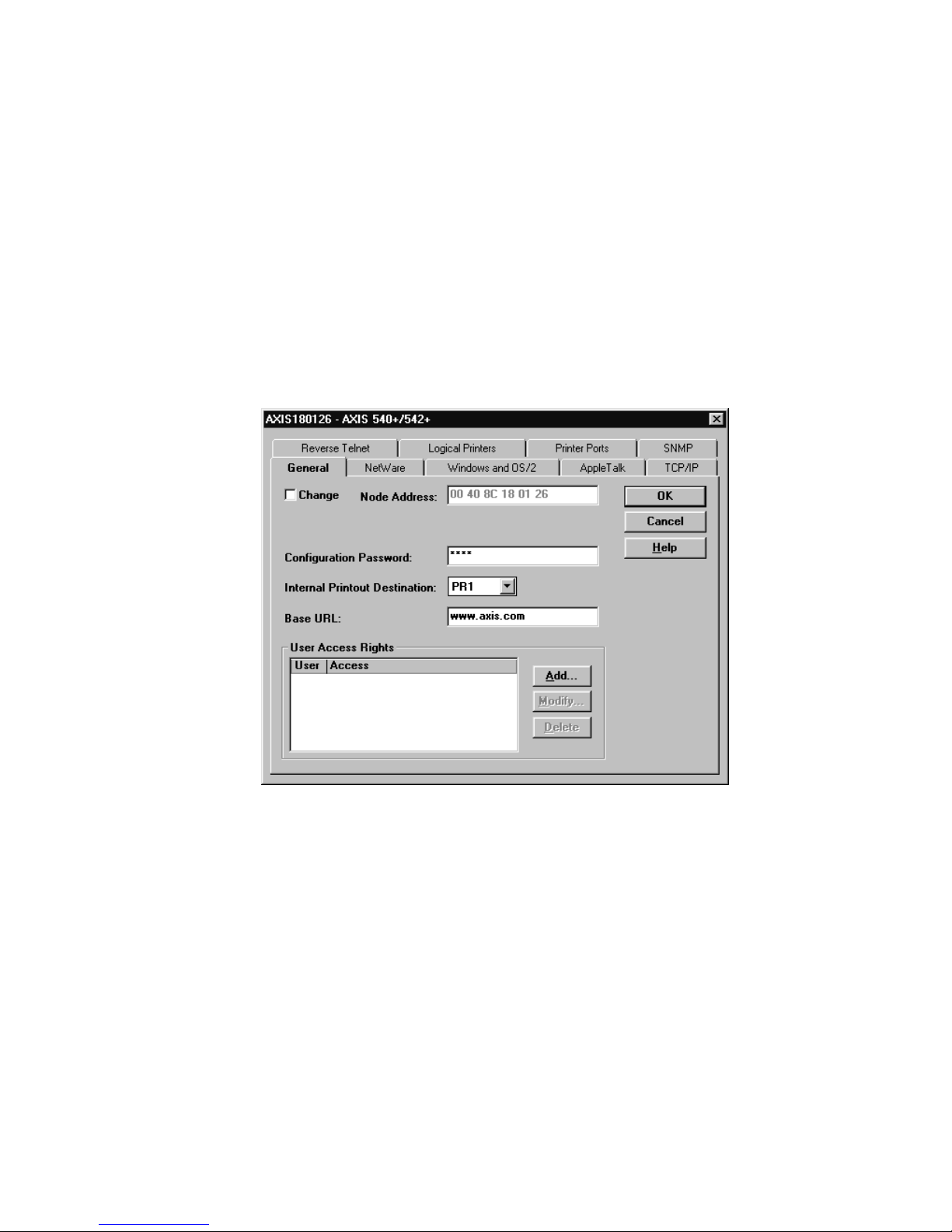
Intermec Ethernet Adapter User’s Manual
To open and edit a property page
1. Select the Ethernet adapter from the “Network Print Servers” folder.
2. Click the Properties button on the AXIS NetPilot toolbar or select Properties from
the Setup menu.
3. Select the tab that includes the parameter value you want to change.
4. Change the value.
5. Click Apply to save the change to the adapter. If you select OK instead, the
Property pages automatically close after the change has been saved.
Parameter List Editor
The Parameter List Editor is a simple editor residing within AXIS NetPilot. If you are
familiar with the configuration parameters, you can use the Parameter List Editor to
edit the configuration parameters. The Parameter List Editor enables you to
• edit the Ethernet adapter’s configuration file
• save customized configuration files on your hard disk
• configure several network adapters simultaneously
8-8
Page 93

Managing and Configuring the Ethernet Adapter
To use the Parameter List Editor
1. Start the Parameter List Editor by selecting Parameter List from the Setup menu.
2. Upload a configuration file from an adapter or from your hard disk by selecting
from File or from Print Server and click the Load button.
3. The configuration file will open in the editor. After you have done your desired
changes, you can select to save the modified configuration file to one or more
adapters or alternatively to your hard disk. Just click Save after you have made your
choice.
8
Modifying the Network Environments
From the Network Environment window you can modify the network settings for each
supported network environment.
To access the Network Environment window
1. Select the Ethernet adapter from the Network Print Servers folder.
2. Click on the Network button on the toolbar or select Network from the Setup menu.
3. Select the tab corresponding to the environment that you want to modify.
Monitoring Printers
For the purpose of printer monitoring, the AXIS NetPilot allows you to create groups of
printers. The AXIS NetPilot window displays the printers comprising each group. To
examine the status of any printer within a group, click on the appropriate group folder
icon. The status of each printer within a group appears and is marked by a colored icon.
You can create any number of groups and delete unwanted groups. Similarly, you can
include or delete individual printers from any group.
8-9
Page 94

Intermec Ethernet Adapter User’s Manual
Monitoring Printers (continued)
Grouping Logically Connected Adapters
For the purpose of simplifying administration of the Ethernet adapter, the AXIS
NetPilot allows you to create groups of adapters. The adapters comprising each group
appear in the AXIS NetPilot window. To access any adapter within a group, simply
click on the appropriate group folder icon.
You can create or delete any number of adapter groups.
Finding Printer Information
It is possible to obtain extended information about the printers that appear in the
monitoring window of the AXIS NetPilot. To open the Printer Information window,
just click the desired printer and choose Printer Information from the File menu.
8-10
Page 95

Printer Information Window
Managing and Configuring the Ethernet Adapter
8
The printer information is also displayed in the Summary window of every Ethernet
adapter connected to a printer.
8-11
Page 96

Intermec Ethernet Adapter User’s Manual
Using FTP to Manage and Configure the Ethernet Adapter
After you have assigned an IP address to the Ethernet adapter, you can use FTP to view
or edit the following files:
• The configuration file
• The status file
• The account file
Editing the Configuration File
To permanently edit the configuration file, you must type the destination file name in
capital letters. Otherwise the edits are regarded as temporary.
To edit the configuration file from a Macintosh, you will need FTP support such as
MacTCP, Fetch, or Anarchie. The procedure for doing this is the same as described for
UNIX in the previous section.
To edit the configuration file using FTP
1. Log in to the Ethernet adapter by typing the following command in the DOS
window (Windows), in the OS/2 Window, or in the UNIX shell window:
ftp
host_name
2. Enter
root
3. Fetch the configuration file by typing
Note: Type
or ftp
as user id and
instead of
help
IP_address
as password.
pass
get config
get config
.
to see a list of all available files and
commands.
4. Edit the file using your preferred text editor.
5. Save the configuration file by typing
config CONFIG
.
Example
> ftp npserver
connected to npserver.
220 AXIS 540/640 FTP Print Server v5.51 Apr 17 1998 ready.
Name (npserver:thomas):
331 User name ok, need password
pass
Password:
230 User logged in
ftp>
200 PORT command successful.
150 Opening data connection for config (192,36,253,4,13,223),
(mode ascii).
get config
(not visible)
root
8-12
Page 97

Managing and Configuring the Ethernet Adapter
226 Transfer complete.
8588 bytes received in 0.24 seconds (35.63 kbytes/s)
ftp>
200 PORT command successful.
150 Opening data connection for CONFIG (192,36,253,4,13,223),
(mode ascii).
226 Transfer complete.
8588 bytes received in 0.45 seconds (19.04 kbytes/s)
ftp>
221 Goodbye.
>
config CONFIG
bye
8
Viewing the Status File
The status command shows which printer port the logical printers are assigned to and
their current status.
To view the status file using FTP
1. Log in to the Ethernet adapter by typing the following command in the DOS
window (Windows), in the OS/2 Window, or in the UNIX shell window:
ftp
host_name
2. Enter
3. Fetch the status file by typing
4. View the status file using your preferred text editor.
root
Type
Note:
commands.
or
ftp
as user id and
instead of
help
IP_address
as password.
pass
get status
get status
.
to see a list of all available files and
Viewing the Account File
The account file contains data concerning the 10 last print jobs. It specifies an internal
job number, the user that initiated the job, the protocol and logical printer that was
used, current status (Completed, Off-line, or Printing), number of bytes printed, elapsed
time, and off-line time.
To view the account file using FTP
1. Log in to the Ethernet adapter by typing the command in the DOS window
(Windows), in the OS/2 Window, or in the UNIX shell window:
ftp
host_name
or ftp
IP_address
2. Enter
3. Fetch the account file by typing
as user id and
root
as password.
pass
get account
.
8-13
Page 98

Intermec Ethernet Adapter User’s Manual
Note: Type help
commands.
4. View the account file using your preferred text editor.
instead of
get account
to see a list of all available files and
Using Telnet to Manage and Configure the
Ethernet Adapter
After you have assigned an IP address to the Ethernet adapter, you can use Telnet to
view the accounting and status files of the Ethernet adapter and perform soft and hard
resets.
Viewing the Accounting File
The accounting file contains data concerning the last 10 print jobs. It specifies an
internal job number, the user that initiated the job, the protocol and logical printer that
was used, current status (Completed, Off-line, or Printing), number of bytes printed,
elapsed time, and off-line time.
To view the account file using Telnet
1. Log in to the Ethernet adapter by typing the command in the DOS window
(Windows), in the OS/2 Window, or in the UNIX shell window:
telnet
2. Enter
3. View the account file by typing
Note: Type
The following example shows how to view the accounts file using Telnet from a UNIX
window.
> telnet npserver
Trying 192.36.253.96...
Connected to npserver.
Escape character is ‘^]’.
AXIS 540/640 TELNET Print Server v5.51 Apr 17 1998
AXIS 540/640 network login: root
Password:
account
Root>
host_name
as user id and
root
help
pass
or telnet
pass
instead of
IP_address
as password.
account
account
(not visible)
.
to see a list of all available commands.
8-14
Page 99

Managing and Configuring the Ethernet Adapter
Current account file:
JOB USER PROT LPR S BYTES ETIME OTIME
1 Thomas FTP pr2 C 1885 2 0
2 Joe LPT pr1 C 23074 4 0
3 RICHARD PSERVER pr2 C 43044 5 0
4 MacUser APPLE pr1 C 6717 2 0
5 LSLM_user NetBIOS pr2 C 36995 3 0
6 patrick PROS pr5 P 83208 9 0
Root>
8
Viewing the Status File
The status file shows which printer port the logical printers are assigned to and their
current status.
To view the status file using Telnet
1. Log in to the Ethernet adapter by typing the command in the DOS window
(Windows), in the OS/2 Window, or in the UNIX shell window:
telnet
2. Enter
3. View the status file by typing
Note:
host_name
as user id and
root
Type
help
or telnet
instead of
as password.
pass
status
status
IP_address
.
to see a list of all available commands.
Performing Resets
Three types of reset commands allow you to perform soft and hard resets and allow you
to reset the adapter’s parameters to its default settings.
To perform a soft reset using Telnet
1. Log in to the Ethernet by typing the command in the DOS window (Windows), in
the OS/2 Window, or in the UNIX shell window:
telnet
2. Enter
3. Restart the adapter’s protocols by typing
Note:
host_name
as user id and
root
Type
help
or telnet
instead of
as password.
pass
softreset
IP_address
softreset
to see a list of all available commands.
.
Replace the command in Step 3 above with
of the other two resets.
hardreset
or
default
to perform either
8-15
Page 100

Intermec Ethernet Adapter User’s Manual
Using SNMP to Manage and Configure the Ethernet Adapter
You may use SNMP for remote monitoring of the Ethernet adapter. All major functions
applicable to adapters are supported.
SNMP actually refers to a set of standards for network management, including a
protocol, a database structure specification, and a set of data objects. The Ethernet
adapter SNMP implementation runs in the TCP/IP environment.
Network management system (NMS) software running on a host on your network
handles the actual management. The NMS software sends messages referring to one or
more objects to the network devices.
A message can contain a question or an instruction to a device or an alarm triggered by
a specific event in a device. Databases, called management information bases (MIBs),
hold the objects. MIB-II is a standard database.
The Ethernet adapter supports all relevant parts of MIB-II. It also includes a private
enterprise MIB.
System Requirements for SNMP
Your system must have the following to make full use of the Ethernet adapter SNMP
support:
• NMS software that allows you to install private enterprise MIBs.
• A host that supports FTP to run the NMS software.
To add the AXIS MIB to your NMS software
1. Log in to the Ethernet adapter using FTP.
2. Upload the MIB file
3. Install the AXIS MIB according to instructions in your NMS software
documentation.
/snmp/axis.mib
to the NMS host.
About AXIS MIB
The AXIS MIB contains a large number of objects that may be categorized as follows:
• Menu objects, which are used for viewing and changing the Ethernet adapter’s
configuration from the NMS program. For a list of the Ethernet adapter’s
parameters, see Appendix B.
• Printer status and unit administration objects, which are used for monitoring
Ethernet adapter print jobs and storing parameter changes permanently.
• Trap objects, which are used for alarms at various error conditions.
For technical details, you can view the MIB file (
8-16
axis.mib
) with any text editor.
 Loading...