

Page 1

Service Manual
EasyCoder PC4
Bar Code Label
Printer
Page 2

Intermec Technologies Corporation
Corporate Headquarters
6001 36th Ave. W.
Everett, WA 98203
U.S.A.
www.intermec.com
e information contained herein is proprietary and is provided solely for the purpose of allowing
customers to operate and/or service Intermec manufactured equipment and is not to be released,
reproduced, or used for any other purpose without written permission of Intermec.
Information and specifications in this manual are subject to change without notice.
© 2005 by Intermec Technologies Corporation. All Rights Reserved
EasyCoder, EasyLAN, Fingerprint, and LabelShop are registered trademarks of Intermec Tech
nologies Corp. e word Intermec, the Intermec logo, InterDriver, and PrintSet are trademarks of
Intermec Technologies Corp.
e name Centronics is wholly owned by GENICOM Corporation.
Microsoft is a registered trademark of Microsoft Corporation.
Windows is a trademark of Microsoft Corporation.
roughout this manual, trademarked names may be used. Rather than put a trademark (™) symbol
in every occurrence of a trademarked name, we state that we are using the names only in an editorial
fashion, and to the benefit of the trademark owner, with no intention of infringement.
Page 3

Intermec EasyCoder PC4—Service Manual iii
Preface
Contents
About is Manual ...............................................................................................................v
Notices and Approvals ..........................................................................................................
vi
1
Models and Options 1
1.1 Models............................................................................................................................ 2
1.2 Options ...........................................................................................................................
3
1.3 EasyCoder PC4 Specifications ........................................................................................
4
1.4 EasyCoder PC4 Measures ...............................................................................................
6
2
Main Parts 9
2.1 Taking the Printer Apart ................................................................................................10
2.2 Reassembling the Printer ...............................................................................................
10
2.3 Exploded View ..............................................................................................................
11
3
Top Cover 13
3.1 Description................................................................................................................... 14
3.2 Tear-Off Plate ................................................................................................................
15
4
Print Frame 17
4.1 Description.......................................................... .........................................................18
4.2 LED and Feed Switch ...................................................................................................
19
4.3 Top Cover Locks ...........................................................................................................
21
4.4 Base Lock Spring Hooks ...............................................................................................
21
4.5 Printhead ......................................................................................................................
22
4.6 Ribbon End Sensor .......................................................................................................
25
4.7 Label Gap Sensor (Emitter) ...........................................................................................
27
4.8 Ribbon Feed Mechanism ..............................................................................................
28
5
Base Frame 33
5.1 Main Parts..................................................................................................................... 34
5.2 Main Board ...................................................................................................................
35
5.3 Platen Roller .................................................................................................................
36
5.4 Peel-Off Mechanism ......................................................................................................
37
5.5 Motor assy ....................................................................................................................
39
5.6 Media Guides ................................................................................................................
40
5.7 Base Locks ....................................................................................................................
41
5.8 Label Gap/Black Mark Sensors ......................................................................................
43
5.9 Media Spindle ...............................................................................................................
45
6
Bottom Cover 47
6.1 Bottom Cover ...............................................................................................................48
Page 4

iv Intermec EasyCoder PC4—Service Manual
Preface
7
Main Board 49
7.1 Description................................................................................................................... 50
7.2 Accessing the Main Board .............................................................................................
51
7.3 Connections ..................................................................................................................51
7.4 Test Points .....................................................................................................................
52
7.5 Block Diagram ..............................................................................................................
54
7.6 Internal Memory ...........................................................................................................
55
7.7 Schematics ....................................................................................................................56
8
Power Supply 61
8.1 Description.................................................................................................................... 62
9
Memory Cartridge (option) 63
9.1 Description................................................................................................................... 64
9.2 Memory Sizes ................................................................................................................
65
9.3 Schematics ....................................................................................................................66
10
Starting Up 67
10.1 Normal Mode .............................................................................................................68
10.2 Test Mode ...................................................................................................................
69
10.3 Dump Mode ...............................................................................................................
70
11
Firmware Upgrading 71
11.1 Requirements ..............................................................................................................72
11.2 Step-by Step Instructions ............................................................................................
73
12
Troubleshooting 75
12.1 Checklist..................................................................................................................... 76
Page 5

Intermec EasyCoder PC4—Service Manual v
Preface
About This Manual
is Service Manual is intended to facilitate installation, troubleshooting
and repair of the Intermec EasyCoder PC4 in the version delivered at the
date of publishing. us, all information on the ESim firmware is based on
version 6.xx. e on-going product improvement can be followed in the
Technical Bulletins published at the Intermec Knowledge Center.
is Service Manual is supplemented by the following publications, which
the service technician also should keep easily available in their latest ver
-
sions:
• Intermec EasyCoder PC4, Quick Start Guide (multilingual)
• Intermec EasyCoder PC4, User’s Guide
• Intermec EasyCoder PC4, Spare Parts Catalog
• ESim v6.xx, Programmer’s Reference Manual
Please note that the operations described in this manual only should be car
ried out by skilled and authorized personnel with proper training and full
understanding of written English. Moving parts may cause harm, if incor
-
rectly manipulated.
It is assumed that the reader possesses adequate skills in mechanics and
electronics and is familiar with the ESim protocol and its related standard
application programs. It is also assumed that the reader has access to the
standard tools of an electronics workshop.
Page 6

vi Intermec EasyCoder PC4—Service Manual
Preface
FCC Notice (United States of America)
WARNING
is equipment generates, uses, and can radiate radio frequency energy
and if not installed and used in accordance with the instructions manual,
may interfere with radio communications. It has been tested and found to
comply with the limits for a Class A computing device pursuant to Sub
part J of Part 15 of FCC Rules, which are designed to provide reasonable
protection against such interference when operated in a commercial envi
ronment. Operation of this equipment in a residential area is likely to cause
interference in which case the user, at his own expense, will be required to
take the appropriate measures needed to correct the problem.
DOC Notice (Canada)
Canadian Dept. of Communication
REGULATIONS COMPLIANCE
(DOC-A)
is digital apparatus does not exceed the class A limits for radio noise
emissions from a digital apparatus as set out in the radio interference regu
-
lations of the Canadian Department of Communication.
Ministère des Communications du Canada
CONFORMITE DE REGLEMENTS
(DOC-A)
Le présent appareil numérique n’émet pas de bruits radio-électriques dépassant les limites applicables aux appareils numériques de classe A prescrites
dans le règlement sur brouillage radioélectrique édicté par le Ministère des
Communications du Canada.
EU Standard EN 55022 (The European Union)
WARNING
is is a Class A ITE product. In a domestic environment this product
may cause radio interference in which case the user may be required to take
adequate measures.
Notices and Approvals
Page 7

Intermec EasyCoder PC4—Service Manual 1
1
Models and Options
is chapter provides information on the various models of the EasyCoder
PC4 and contains specifications and physical measures.
Page 8
2 Intermec EasyCoder PC4—Service Manual
Chapter 1—Models and Options
1.1 Models
ere are two main models of the EasyCoder PC4; one dedicated direct
thermal (DT) model and one dual-capable direct thermal/thermal transfer
(TTR) model. Both models are based on a common double clam-shell
mechanical platform and have the same type of electronics, so except from
the fact that the direct thermal model has no transfer ribbon mechanism,
there are very few differences.
Both models are available with two different printheads; one with a density
of 203.2 dots per inch (8 dots per mm) and a maximum print width of 4.1
inches (104 mm), and another with a density of 300 dots per inch (11.81
dots per mm) and a maximum print width of 4.02 inches (102.2 mm).
Since there is no need to open the top cover in the DT model, the top
cover locks are cut off in flush with the bottom of the print frame.
e machine label, which provides information on model, part number,
serial number, etc. is attached to the bottom of the base frame.
e EasyCoder PC4 has a separate power supply unit that delivers 24
VDC to the printer's main board, where it is transformed to the various
voltages required by the printhead, motor, and logics (see Chapter 8.1).
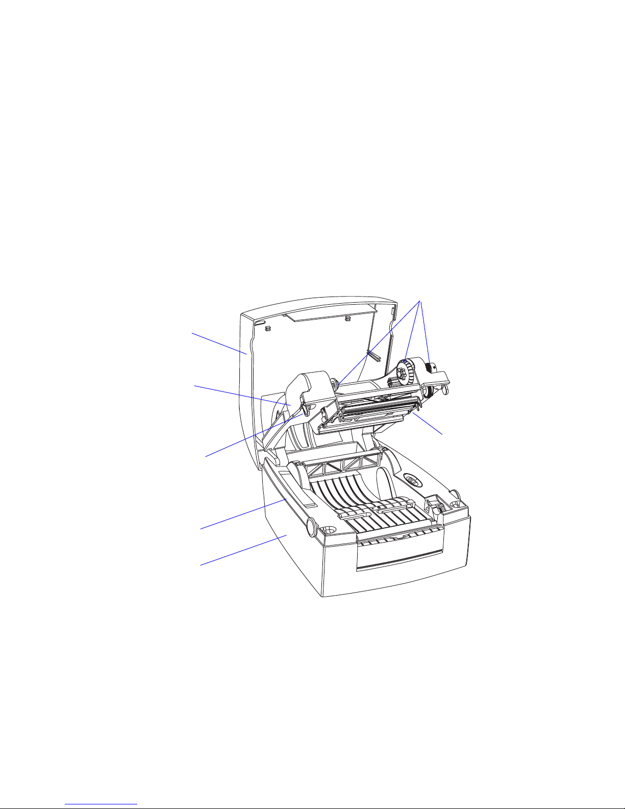
Thermal transfer
mechanism
(omitted in DT model)
Printhead
Top cover locks
(differ in DT and
TTR models)
Print frame
Top cover
Base Frame
Bottom Cover
Page 9

Intermec EasyCoder PC4—Service Manual 3
Chapter 1—Models and Options
e power supply unit (PSU) accepts 100 to 240 VAC/50 to 60 Hz. e
power supply has a standard 2-pin input voltage socket, so various types of
power cords can be used according to local voltages and standards.
e power supply has a fixed 1.5 m (4.9 ft) long cable that is connected to
the printer’s rear plate.
1.2 Options
e available options for the EasyCoder PC4 are memory cartridges, USB,
serial and parallel interface cables, a keyboard/display unit, a paper cutter,
a battery unit and an assortment of power cords. Refer to the EasyCoder
PC4, Spare Parts Catalog
or Spare Parts List for updated information.
Page 10

4 Intermec EasyCoder PC4—Service Manual
Chapter 1—Models and Options
1.3 EasyCoder PC4 Specifications
Printing
Print Technique ermal Transfer and/or Direct ermal
Printhead Resolution
203.2 dpi (8 dots/mm) or
300 dpi (11.81 dots/mm)
Print Speed (selectable) 30, 40, 50, 75 or 100 mm/sec.
(1.2,1.6, 2, 3 or 4 in/sec.)
Print Width (max) at 203.2 dpi 104 mm (4.1 inches) = 832 dots
Print Width (max) at 300 dpi
102.2 mm (4.02 inches) = 1208 dots
Print Length (min/max) at 203.2 dpi 6.35/472.5 mm (0.25/18.6 inches) Standard (no cartridge)
Print Length (min/max) at 300 dpi 6.35/220.0 mm (0.25/8.66 inches) Standard (no cartridge)
Media Width (min/max) 25.4 to 118 mm (1.00 to 4.65 inches)
Media ickness (min) 0.06 mm (0.003 inches)
Media ickness, rolls (max) 0.15 mm (0.006 inches)
Media ickness, fan-folds (max) 0.17 mm (0.006 inches)
Media Roll Diameter (max) 127 mm (5.0 inches)
Media Roll Core Diameter 25.4 or 38.1 mm (1.0 or 1.5 inches)
Ribbon Width (min/max) 33 to 110 mm (1.33 to 4.33 inches)
Ribbon Roll Diameter, Outer (max) 41 mm (1.6 inches)
Ribbor Roll Core Diameter, Inner 13 mm (0.5 inches)
Print Directions 4
Modes of operation
Tear Off (Straight-through) Yes
Peel Off (Self-strip) Yes
Firmware
Operating System Intermec ESim v6.xx
Fonts 5 resident
Font Magnification Horizontal max 8 times, vertical max 9 times
Built-in Bar Code Symbologies
33
Physical Measures
Dimensions (W × L × H) 230 × 257 × 167 mm
(9.06 × 10.11 × 6.58 inches)
Weight (excluding PSU and media) Approx. 2.3 kg (5 pounds) Depending on model
Ambient Operating Temperature +5°C to +40°C (+41°F to +104°F)
Ambient Storage Temperature
-20°C to +50°C (-4°F to +122°F)
Humidity
10 to 90% non-condensing
Electronics
Microprocessor 16-bit 20 MHz (16M of address space)
On-board Flash memory 1024K (774K firmware, 250K available to user)
On-board RAM memory 2048K (576K firmware, 1050K print buffer)
Power Supply Unit Separate unit
Input Voltage 100 to 240 VAC, 50 to 60Hz, 1.9A
Output Voltage 24 VDC, 3.0A
Input Voltage (mobile applications) 23.5 VDC ± 0.5V, 6A peak No PSU connected
Page 11

Intermec EasyCoder PC4—Service Manual 5
Chapter 1—Models and Options
Sensors
Label Gap/Black Mark/Out of Paper Yes
Label Taken Yes Not with cutter
Print Frame Open/Closed Yes
Ribbon End Yes TTR model only
Head up (DOOR L & R) Yes
Controls
Control Lamps
1 Tri-colored LED
Feed Button 1
Data Interfaces
Serial
1 × RS-232 + 1 × USB(v1.1)
Parallel
1 × Centronics
Accessories and Options
Parallel Interface Cable Standard
RS-232 Cable Option
Memory Cartridge Option 1MB flash
Keyboard/Display Unit Option
Paper Cutter Option
V-spring for stiff/thick media Option
>150µm/5.9 mils
Mobile Battery Unit Option
Battery Pack Option
Battery Charger Option
USB cable Option
Page 12
6 Intermec EasyCoder PC4—Service Manual
Chapter 1—Models and Options
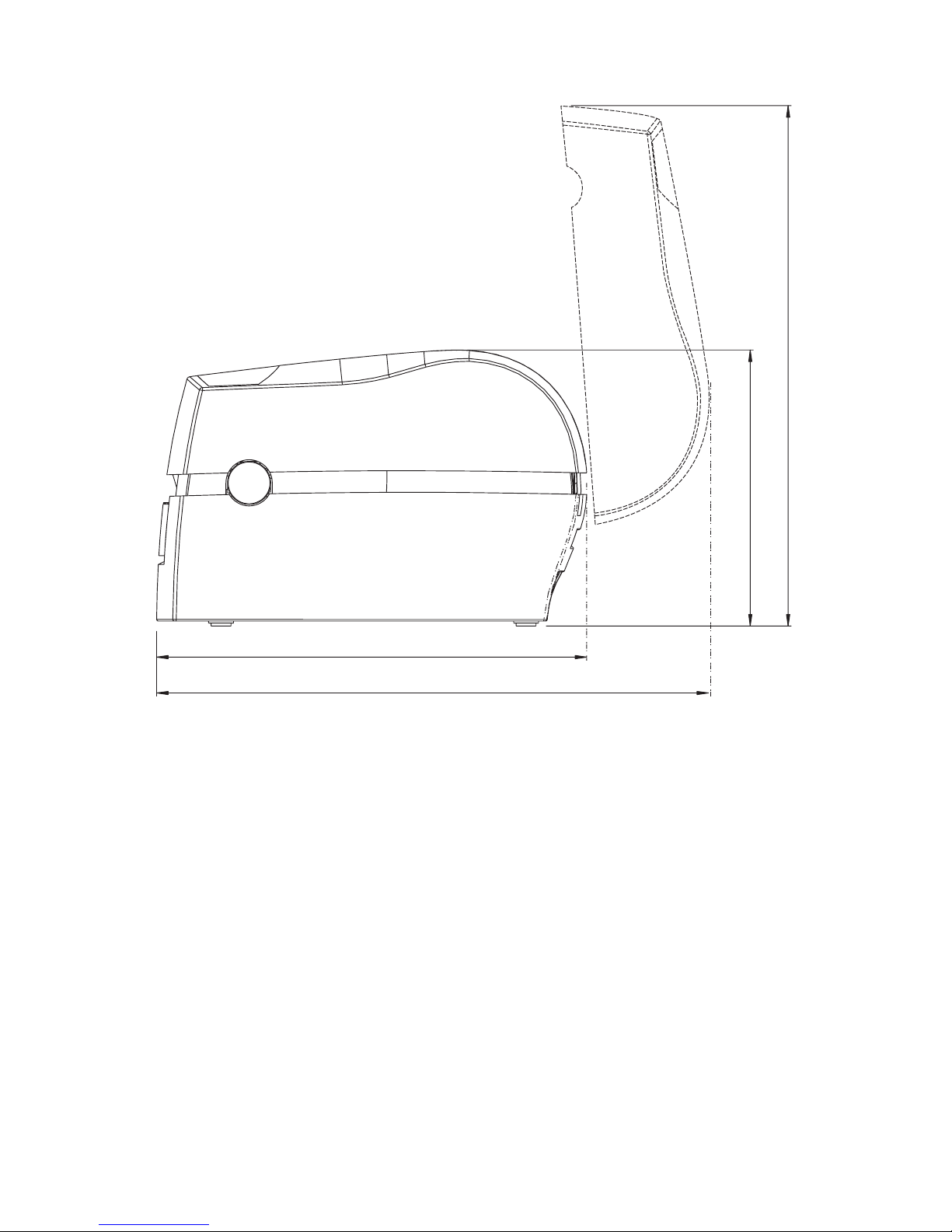
259 mm (10.20 in)
166 mm (6.54 in)
314 mm (12.36 in)
333 mm (13.11 in)
1.4 EasyCoder PC4 Measures
Side View
Page 13
Intermec EasyCoder PC4—Service Manual 7
Chapter 1—Models and Options
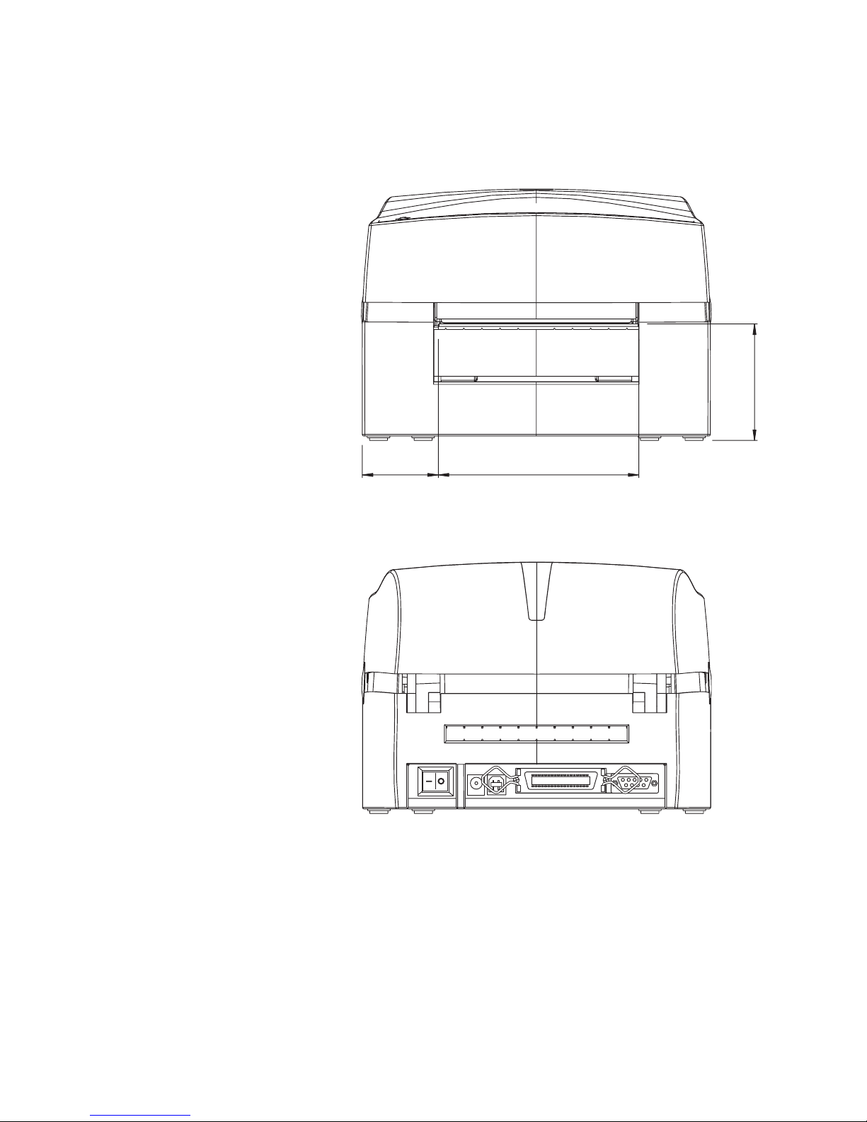
50 mm (1.97 in) 133 mm (5.24 in)
77 mm (3.03 in)
Front View
Rear View
Page 14
8 Intermec EasyCoder PC4—Service Manual
Chapter 1—Models and Options
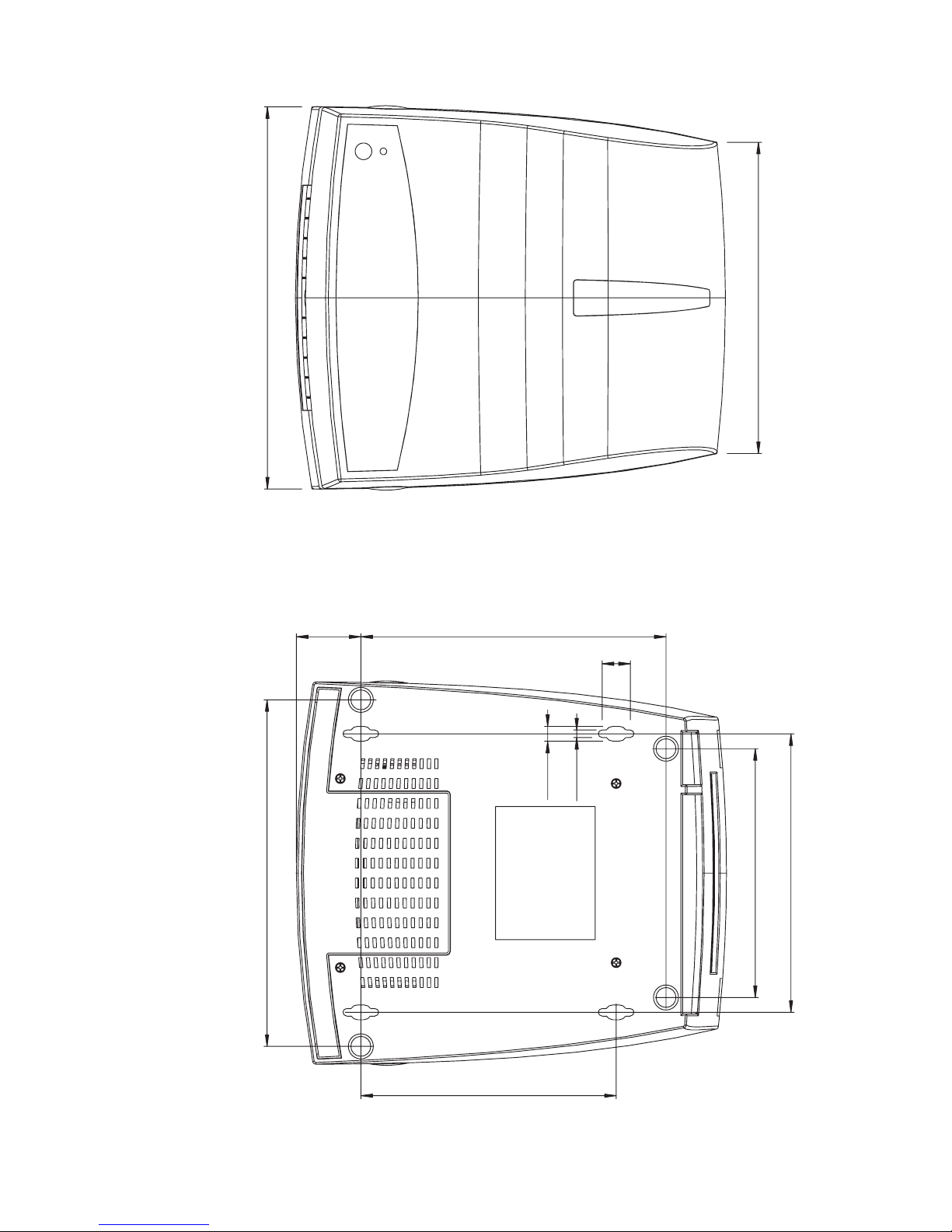
230 mm (9.06 in)
188 mm (7.40 in
)
39 mm (1.54 in)
17 mm (0.67 in)
9 mm (0.35 in)
168 mm (6.61 in)
209 mm (8.83 in)
150 mm (5.91 in)
4.6 mm (0.18 in
)
184 mm (7.24 in)
154 mm (6.06 in
)
Top View
Bottom View
Page 15

Intermec EasyCoder PC4—Service Manual 9
2
Main Parts
is chapter shows the printer’s main parts and explains how the printer is
taken apart and reassembled. Each of the main parts is described in more
detail in the chapters that follow.
Page 16

10 Intermec EasyCoder PC4—Service Manual
Chapter 2—Main Parts
2.1 Taking the Printer Apart
e EasyCoder PC4 is a so called double clam-shell design, where the print
frame and the top cover are hinged to a base frame.
e bottom part of the base frame is enclosed by the bottom cover, which
is held by four Phillips screws. Once the bottom cover has been removed,
the two pairs of bolts and E-rings that hold the base frame, the print frame,
and the top cover become accessible. You will also need to disconnect a
number of cables from the main board.
In most cases, you do not need to dismantle the base frame, print frame,
and top cover.
In the illustration in Chapter 2.3, all cables have been omitted. Detailed
descriptions of the main parts and their sub-assemblies can be found in
Chapters 3 to 7.
All screws are Phillips-type of various sizes.
2.2 Reassembling the Printer
Reassemble the printer in reverse order. Refer to Chapter 7.3 for a connection diagram, which helps you put all the cables back correctly. When put
ting the printer back into the bottom cover, tilt it a little so the rear plate is
inserted first, then carefully manipulate the front part in place. Secure the
assembly with the four Phillips screws.
Page 17
Intermec EasyCoder PC4—Service Manual 11
Chapter 2—Main Parts
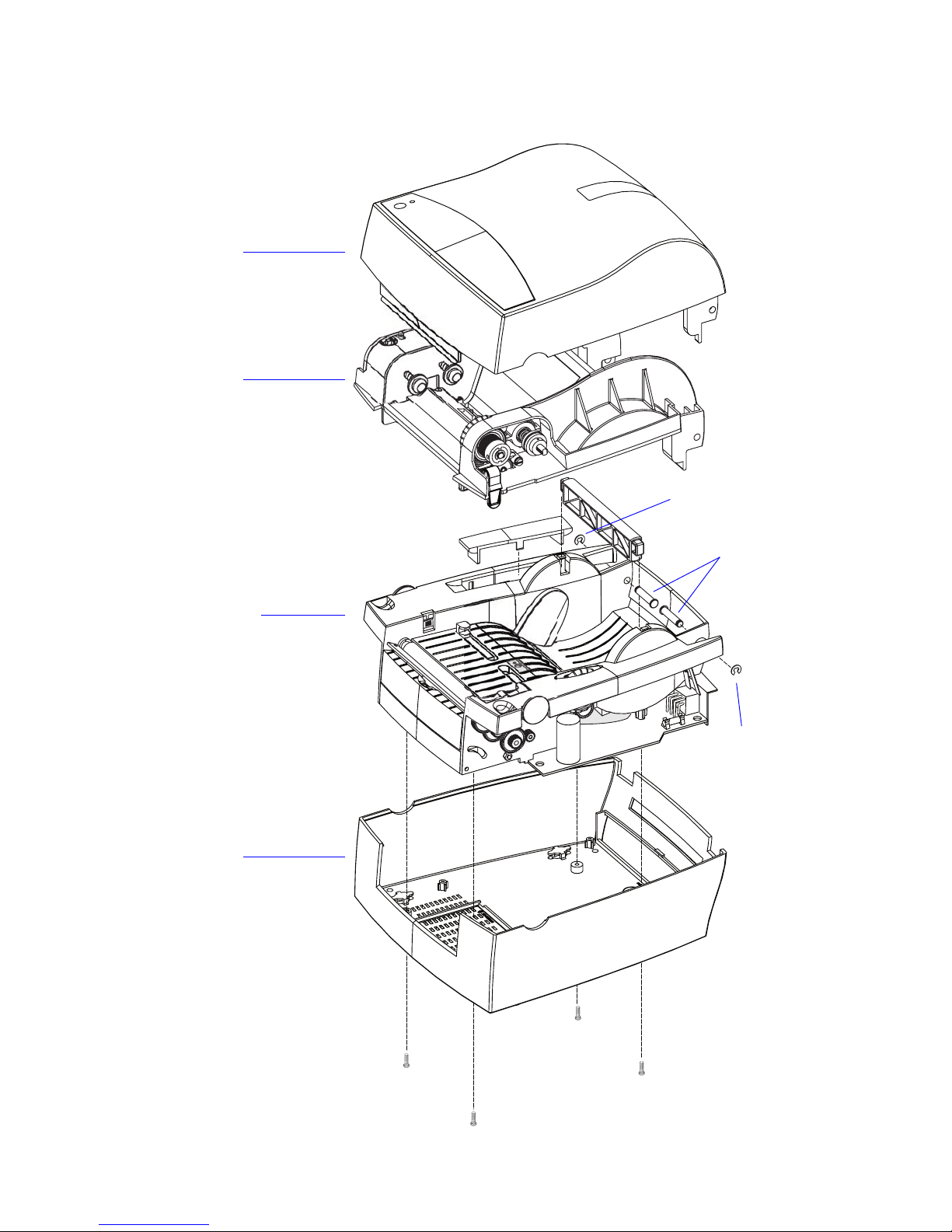
2.3 Exploded View
Top Cover
Print Frame
Base Frame
Bottom Cover
Bolts
E-ring
E-ring
Page 18

12 Intermec EasyCoder PC4—Service Manual
Chapter 2—Main Parts
Page 19

Intermec EasyCoder PC4—Service Manual 13
3
Top Cover
is chapter describes the parts of the top cover and explains how to
replace the tear-off plate.
Page 20
14 Intermec EasyCoder PC4—Service Manual
Chapter 3—Top Cover
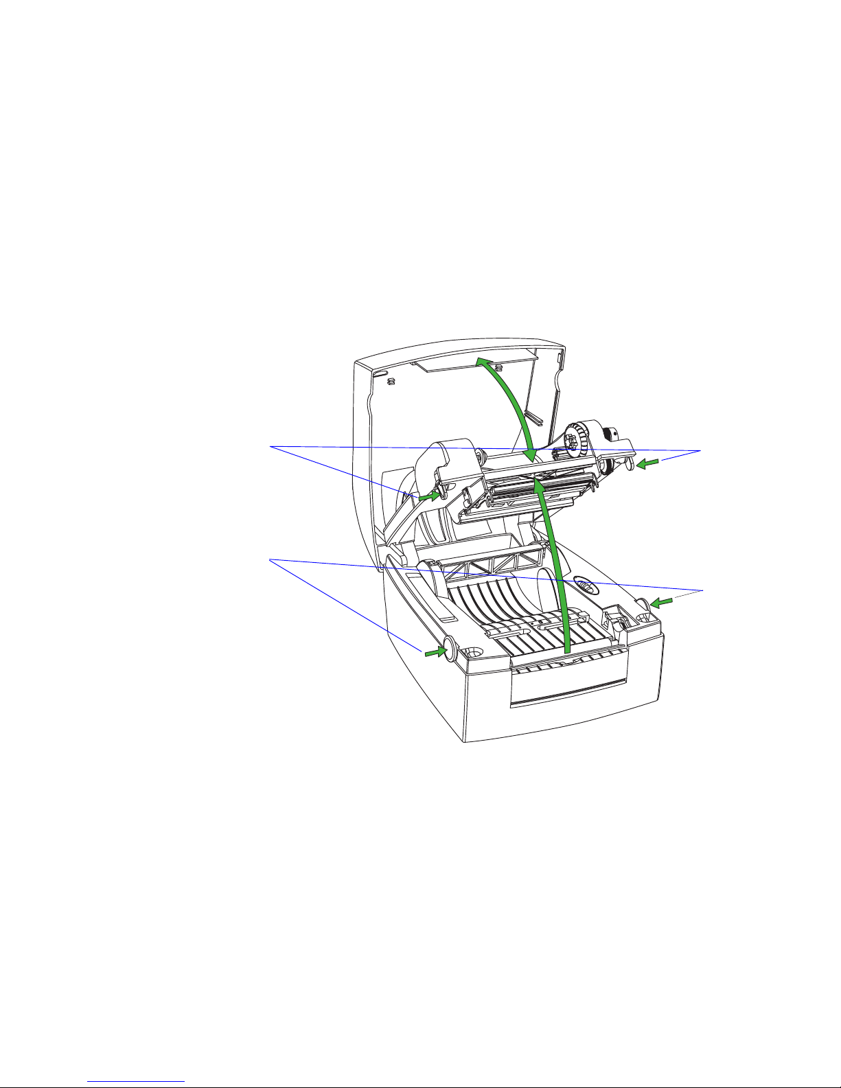
3.1 Description
e top cover encloses the print frame. It is attached to the base frame
using the same pair of bolts and E-rings as the print frame. e top cover
and the print frame opens together when the base locks on either side of
the printer are pressed. en the top cover can be released from the print
frame by pressing the two green locks at either side of the print frame, as
shown below. Note that in case of a PC4 DT printer, the locks are cut off
and you will need to insert a flat screwdriver or similar to release the locks.
Base locks
Top cover locks
Page 21

Intermec EasyCoder PC4—Service Manual 15
Chapter 3—Top Cover
e top cover is made up of the following parts:
• Top cover plastic moulding
• Clear plastic window (permanently glued to the moulding)
• Two media load instruction labels
• Tear-off plate (snap-locked to the moulding)
• Name plate (glued to the moulding)
3.2 Tear-Off Plate
e only part that can be replaced easily is the tear-off plate. It is provided
with two snap-lock tabs that engage bars at the inside of the top cover. Two
L-shaped rails hold the plate. If you need to remove the tear-off plate with
-
out discarding it, be careful not to break the tabs, which are quite delicate.
Top cover moulding
Clear window
Tear-off plate
Name plate
Page 22

16 Intermec EasyCoder PC4—Service Manual
Chapter 3—Top Cover
Page 23

Intermec EasyCoder PC4—Service Manual 17
4
Print Frame
is chapter describes the print frame which contains the thermal printhead, the transfer ribbon supply, the LED control lamp, the Feed key, and
the emitter of the label gap sensor. It also provides instructions for how to
replace the various parts.
Page 24

18 Intermec EasyCoder PC4—Service Manual
Chapter 4—Print Frame
4.1 Description
e print frame comes in two versions; one for the DT model and another
for the TTR model. Both are based on the same plastic moulding. ey
both have either a 203.2 dpi (8 dots/mm) printhead or a 300 dpi (11.81
dots/mm) printhead.
Direct Thermal (DT) Model
Thermal Transfer (TTR) Model
Print frame moulding
LED control lamp
Feed switch
(No ribbon load label)
(No transfer
ribbon mechanism)
(No ribbon end sensor)
Short top cover locks
Print frame moulding
LED control lamp
Feed switch
Ribbon load label
Transfer
ribbon mechanism
Ribbon end sensor
Long top cover locks
Printhead
Printhead
Label gap sensor
(Emitter)
Label gap sensor
(Emitter)
Page 25

Intermec EasyCoder PC4—Service Manual 19
Chapter 4 —Print Fram
4.2 LED and Feed Switch
Description
e LED control lamp and Feed switch are fitted on the same Feed Switch
PCB inside a housing on the left side of the print frame. e board is con
nected to JP9 on the main board via a four cables that run inside the left
side hinge of the print frame. e control lamp shines through a transpar
ent window and the Feed switch is activated via a dome, both in the name
plate on the top cover.
Replacement
e Feed Switch PCB can be accessed for replacement by removing the
cable cover, which is held in place by a Phillips screw and a snap lock. e
Feed Switch PCB is inserted between two rails in the moulding and is cov
-
ered by an isolation sheet.
Green (solid) Media loaded
Ribbon loaded (TTR only)
Green (flashing) Receiving data
(T
est Mode only)
Red (solid) Out of media
Out of ribbon (TTR only)
Printer reset
Red (short flashes) Upgrading firmware
Ov
ertemperature
Red (long flashes) Media jam in cutter
Ov
erheated printhead or
stepper moto
r
Orange
Error condition detecte
d
Dark
Po
wer off
Color Meaning
Feed switch PCB
Cable cover
Screw
Snap lock
Print frame
Isolation sheet
Page 26
20 Intermec EasyCoder PC4—Service Manual
Chapter 4—Print Frame
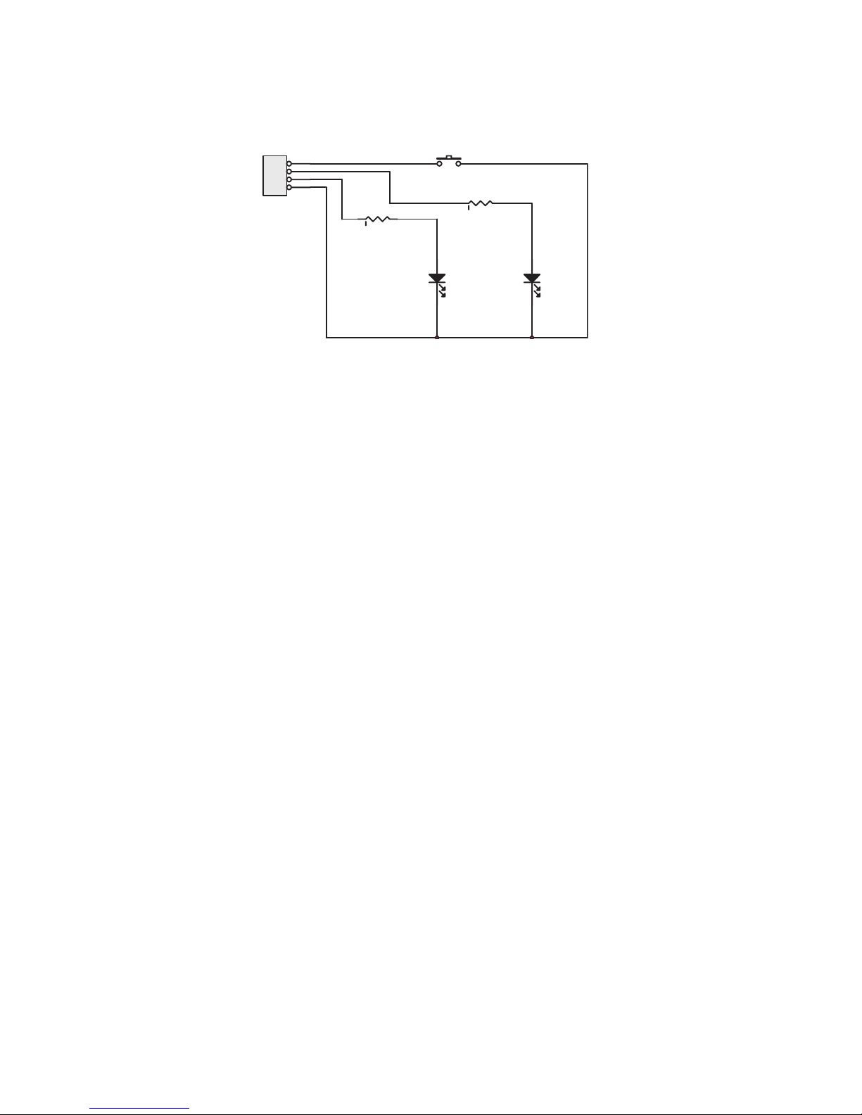
Schematics
JP1
1
2
3
4
LED1
RED
SW1
LED1
YELLO
W
R1
R2
Page 27
Intermec EasyCoder PC4—Service Manual 21
Chapter 4 —Print Fram
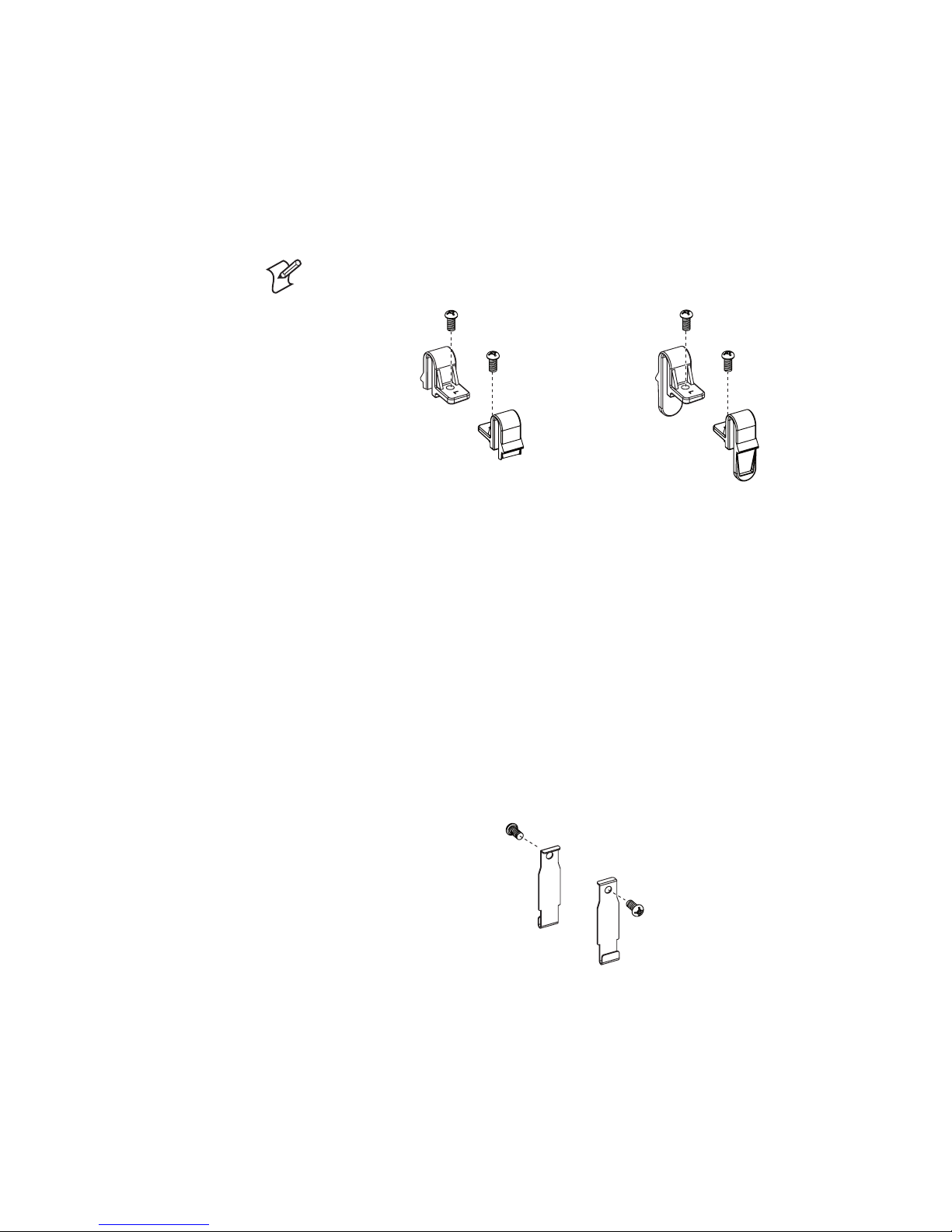
4.3 Top Cover Locks
Description
e top cover locks are shorter in the DT model than in the TTR model,
because there is normally no need to separate top cover and the print
frame, when there is no need for ribbon reload.
Note: Parts are marked with “L” or “R” indicating left or right side (frontal
view).
DT Model TTR Model
Replacement
e locks are attached to the print frame moulding with Phillips screws. To
access the left side lock, you will need to remove the cable cover as shown
in the instructions for replacing the Feed Switch PCB earlier in this chap
-
ter.
4.4 Base Lock Spring Hooks
Description
Two spring hooks that are engaged by the base lock (see Chapter 5.7) are
fitted to the print frame moulding using Phillips screws. e spring hooks
are identical for the DT and TTR models.
Replacement
e left-side spring hook is fitted inside the same housing as the Feed
switch PCB. To access it, you will need to remove the cable cover as shown
in the instructions for replacing the Feed Switch PCB earlier in this chap
-
ter.
e right-side spring hook is easily accessible in the DT model whereas in
the TTR model, you will need to dismantle the ribbon takeup mechanism
(see Chapter 4.8).
Page 28

22 Intermec EasyCoder PC4—Service Manual
Chapter 4—Print Frame
4.5 Printhead
Description
ere are two types of thermal printheads; one with a density of 203.2 dpi
(8 dots/mm), and another with a density of 300 dpi (11.81 dots/mm).
ese printheads fits both the DT model and the TTR models. Printheads
need to be replaced at intervals depending on type of printing, print speed,
ambient temperature and other environmental conditions, type of media
and ribbon, etc.
Some simple measures can be taken by the user to prevent premature wearout:
• Clean the printhead regularly, as described in the EasyCoder PC4 User’s
Guide. Not only will a dirty printhead result in an inferior printout, but
any residue on the dots will prevent heat to dissipate through the ribbon
and media.
• Follow the recommendations regarding density setup, see the
D com-
mand in the ESim v6.xx, Programmer’s Reference Manual. Too much
energy to the printhead will wear it out rapidly.
• Do not use higher Print Speed setting than necessary, see the
S com-
mand in the ESim v6.xx, Programmer’s Reference Manual.
• Low ambient temperature requires more energy to the printhead dots
than room temperatures and will therefore cause more wear to the print
head. High print speed accelerates the wear. us, at low temperatures,
select as low a print speed as is acceptable.
• Never print outside the media path. Dots that are not in contact with
the media will not be cooled properly.
• When using preprinted labels or labels with some type of varnish or
non-standard top coating for direct thermal printing, use original
Intermec labels or inks recommended by leading manufacturers of direct
thermal media. e labels must not contain any aggressive substances
such as chloride or grinding substances such as titanium dioxide.
• Only use original Intermec transfer ribbon or ribbons recommended by
Intermec.
Note: ere are two different types of V-springs; a standard type for media
fulfilling the specifications in the EasyCoder PC4 User’s Guide, and a stron
-
ger type for thick and stiff media (>150µm/5.9 mils). e latter is recog
-
nized by its yellow paint coating.
Page 29

Intermec EasyCoder PC4—Service Manual 23
Chapter 4 —Print Fram
Replacement
e thermal printhead can be replaced without tools.
To reduce the risk of electrostatic discharges, use ESD protection bracelets or similar equipment.
• Open the print frame and remove any transfer ribbon.
• Press the printhead and print frame firmly together so you overcome the
pressure of the V-shaped spring. Be careful not to touch the line of dots
at the front of the printhead, but press against the metal bracket or white
plastic cover.
• While keeping up the pressure, slide the printhead forward so the tabs at
both sides of the printhead bracket become disengaged from the pockets
at the inner sides of the cavity in the print frame.
• Continue to press forward so the U-shaped slots in the sides of the print
head bracket also become disengaged from the studs at the inner sides of
the cavity in the print frame.
Printhead assy
Tab
Pocket
Stud
Slot
V-Spring
Do not touch dot line!
Page 30

24 Intermec EasyCoder PC4—Service Manual
Chapter 4—Print Frame
• Now the printhead assy is free but still connected by three sets of cables.
Disconnect the grounding cable.
• Carefully disengage the snap-locks that hold the printhead cover to the
printhead bracket and remove the cover.
• Disconnect the two remaining cables.
• Remove the V-spring.
• Now you can install the printhead assy in reverse order. e printhead
kit comes as a complete unit including printhead, bracket, cover plate,
ground terminal, screws, and V-spring.
Be careful not to touch the dots on the printhead and make sure that the
tip of the V-spring runs between the two guiding ridges on the printhead
bracket.
• Test that the printhead can move slightly up against the pressure force
of the V-spring. Finally, check that the printhead is working properly by
printing a test label as described in Chapter 10.2.
Printhead bracket
Cable to CNB
on Main Board
Printhead cover
V-Spring guides
Snap-lock
Snap-lock
Cable to CNA
on Main Board
Ground cable teminal
Page 31

Intermec EasyCoder PC4—Service Manual 25
Chapter 4 —Print Fram
4.6 Ribbon End Sensor
Description
e ribbon end sensor is a photoelectric sensor that detects when the
printer runs out of ribbon. It is only fitted in the TTR model of EasyCoder
PC4. A beam of light is transmitted from an LED (light emitting diode)
and reflected back to a receiver by the silvery foil trailer of the ribbon. e
sensor triggers at 4V.
Note: e Ribbon End Sensor only works if the ribbon has a silver-colored
trailer that can reflect the light.
A DT printer can be set to detect ribbon end, and a TTR printer can be
set to ignore ribbon end, without any error being reported (see ESim v6.xx,
Programmer’s Reference Manual
, OD command).
Both the emitter and the receiver are fitted on a small printed circuit board,
which is installed in a pocket on the print frame moulding. A cable runs
inside the left-side hinge of the print frame and down to the main board,
where it is connected to JP7. e same circuit board is also used for the
label taken sensor.
Refer to Chapter 5.2 for an description of how to access the main board.
Replacement
Do not remove the sensor unless you intend to discard it, since you may
damage some of the components when you pull it up.
• Disconnect the cable from JP7 on the main board.
• Remove the cable cover.
• Carefully pry the sensor PCB loose (it may be fitted with a drop of glue)
and pull it straight up using a small pair of pliers while carefully manip
ulating the cable and connecter through the hinge and out through the
wall of the ribbon supply cavity.
• Install a replacement sensor in reverse order.
Ribbon end sensor
Page 32

26 Intermec EasyCoder PC4—Service Manual
Chapter 4—Print Frame
Schematics
RIBBON
S01 S02 R2 R3
YES 150 100K
YES 300STRIPPER
SW1
ON: ENABLE
OFF: DISABLE
ON
OFF
S02
12
3
4
5
R2
S01
1
2
3
4
C1
JP1
1
2
3
R3
SW1
Page 33

Intermec EasyCoder PC4—Service Manual 27
Chapter 4 —Print Fram
4.7 Label Gap Sensor (Emitter)
Description
e label gap sensor consists of two parts, a light emitter fitted in the print
frame and a receiver part fitted in the base frame (see Chapter 5.8). ey
work together with the black mark sensor to determine where a form (that
is, a label, ticket, or tag) starts so the media feed motor can be controlled
by the firmware. e label gap sensor also detects out-of-media conditions.
e label gap sensor emitter consists of a light emitting diode (LED) fitted
on a printed circuit board, which is fitted with a screw and washer in a
pocket on the upper side of the print frame, immediately to the rear of
the ribbon slot. (In the TTR model, the board is hidden under the ribbon
load label.) e LED shines downward through a hole in the print frame
moulding. Before replacing the sensor, check that the hole is not blocked
by dust or similar. e label gap sensor is connected to JP10 on the main
board via a cable running inside the left hand hinge of the print frame.
Replacement
• Disconnect the cable from JP10 on the main board.
• Remove the cable cover.
• Remove the screw that holds the circuit board and pull it straight up
while carefully manipulating the cable and connector through the hinge
and out through the wall of the ribbon supply cavity.
• Install a replacement circuit board in reverse order.
Schematics
Label gap sensor
JP1
1
2
S01
Page 34

28 Intermec EasyCoder PC4—Service Manual
Chapter 4—Print Frame
4.8 Ribbon Feed Mechanism
Description
ough the ribbon feed mechanism is not available as spare parts, it is still
appropriate to descibe how it works. Since it is factory-adjusted, please
refrain from dismantling it on your own.
e ribbon mechanism consists of four different elements, all of which are
attached to the print frame moulding:
• Ribbon supply
• Ribbon core holders
• Ribbon takeup
• Ribbon takeup drive train
In the illustrations that follow, all other parts have been omitted to give a
clearer view.
Ribbon Supply
e ribbon supply mechanism breaks the rotation of the ribbon supply
spool in order to keep the ribbon tight using a spring-loaded friction cou
pling. Another spring dampens sudden jerks. e friction is affected by the
position of the fixed holder along the ribbon supply shaft.
If you need to dismantle this assembly, make sure that the ends of the short
spring fit into the holes in the ribbon return cap and friction plate and
rotate the ribbon return cap so the hook that holds the long spring passes
the 12 o‘clock position (see the arrow). When fitting back the fixed holder,
make sure that the screws hit the indents in the ribbon supply shaft, that
was made when the printer was assembled at the factory.
Ribbon supply shaft
Spring
StarLoc washer
Ribbon return cap
Spring
Friction plate
Wool fiber disc
Fixed holder
Screws (2)
Page 35

Intermec EasyCoder PC4—Service Manual 29
Chapter 4 —Print Fram
Ribbon Core Holders
e ribbon core holders are spring-loaded and hold the ends of the ribbon
cores opposite to the ribbon feed mechanism. A green plastic disc is pressfitted on a metal shaft, that goes through the left-side wall of the print
frame moulding. e shaft is held by an E-ring inside the Feed button
cavity. A spring on the shaft makes it possible to snap the core in place. No
adjustments are facilitated.
E-ring
Washer
Spring
Ribbon core holder
Page 36

30 Intermec EasyCoder PC4—Service Manual
Chapter 4—Print Frame
Ribbon Takeup
e ribbon takeup is driven by the stepper motor via a train of gears and
rotates the ribbon takeup core so the transfer ribbon is pulled forward
along with the media. ere is a spring-loaded friction coupling similar
to the ribbon supply. A large green wheel which engages a one-way clutch
makes it easier to wind up the ribbon leader at ribbon load.
If you need to replace the right-side base lock spring hook, just remove the
E-ring and lift out the entire rewind assembly without dismantling it any
further. is way, you will keep the factory adjustments.
Ribbon rewind shaft
Fixed holder
Screws (2)
E-ring
Spring
Gear
Wool fiber disc
One-way clutch holder
Friction plate
Page 37

Intermec EasyCoder PC4—Service Manual 31
Chapter 4 —Print Fram
Ribbon Takeup Drive Train
e ribbon takeup assembly is driven by the stepper motor via a train of
gears. ere is a spring-loaded arm with two connected gears under the
ribbon takeup. e rear gear engages the gear wheel of the ribbon takeup,
whereas the other gear engages the gear train in the base frame when the
print frame is in closed and locked position. is implies that the ribbon
takeup can be rotated freely in both directions when the print frame is in
open position, but only in one direction when it is closed.
ere are no facilities for adjustments.
Spring
Arm
Gears (2)
E-rings (2)
Bolt
Page 38

32 Intermec EasyCoder PC4—Service Manual
Chapter 4—Print Frame
Page 39

Intermec EasyCoder PC4—Service Manual 33
5
Base Frame
is chapter describes the main parts of the base frame and provides
replacement instructions.
Page 40

34 Intermec EasyCoder PC4—Service Manual
Chapter 5—Base Frame
Platen roller
Peel-off mechanism
(or Paper cutter)
Main board
Memory cartridge blind plate
Peel-off bar
Motor assy
Media guide assy
Base lock assy
5.1 Main Parts
e base frame consists of a plastic moulding to which a number of assemblies are fitted. e same base frame is used for both the DT and the TTR
models of the EasyCoder PC4.
Note that the 203.2 dpi (8 dots/mm) and the 300 dpi (11.81 dots/mm)
printers not only have different firmware versions and printheads, but also
different types of stepper motors. us, modifications of printing density
are not intended.
e optional paper cutter is normally factory-fitted, but could be fieldinstalled by an authorized service technician (see EasyCoder PC4 Cutter,
Installation Instructions). It replaces the standard peel-off mechanism.
Media spindle
Black mark/
Label gap sensor
Label taken sensor
Base frame moulding
Dust protection
sheet
Page 41

Intermec EasyCoder PC4—Service Manual 35
Chapter 5—Base Frame
5.2 Main Board
Description
e main board processes all data and is the connection node for all sensors, the motor, the input voltage, and the computer interfaces. It also has
an On/Off switch and provisions for fitting an optional memory expansion
cartridge. e main board is described in detail in Chapter 7 along with
schematics and a connection diagram.
Replacement
• Make a backup on the host of all files you want to move to the flash
memory of the new board.
• Take precautions to eliminate any electrostatic discharges.
• Make sure the main board is disconnected from any power source.
• Remove the single Phillips screw almost at the center of bottom side of
the board.
• Disconnect all cables to the main board.
• Remove the nut at the top of the rear plate and disconnect the ground
-
ing cable
• Install a new board in reverse order. Refer to Chapter 7.3 for a connec
-
tion diagram.
• Download the saved files from the host to the flash memory of the new
board.
Page 42

36 Intermec EasyCoder PC4—Service Manual
Chapter 5—Base Frame
5.3 Platen Roller
Description
e platen roller feeds the media and provides counter-pressure for the
printhead. It is coated with silicon rubber and driven by the stepper motor
via a train of gears. e media feed is measured in dots, just like the print
width (1 dots = 0,125 mm/4.9 mils).
e platen roller is subject to wear and may need to be replaced.
Replacement
• From above, insert a flat-tipped screwdriver between the gear and the
platen cover and disengage the snap-lock of the platen cover. Pry up the
platen cover.
• Push the right-side bushing to the right to disengage it. en, using
a moderate amount of force, pry the bushing, gear, and platen roller
upwards.
• Lift out the platen roller and the left-side bushing.
• Replace with a new set of platen roller, bushings, and gear in reverse
order. Make sure that the D-plane of the left side bushing fits into the
D-shaped hole, and that the tab on the right-side bushing fits into the
corresponding slot in the base frame moulding before locking the assem
-
bly with the platen cover.
Plastic bushing
with brass insert
Right-side bushing
Tab
Platen roller
Platen cover
Snap-lock
Gear
Page 43

Intermec EasyCoder PC4—Service Manual 37
Chapter 5—Base Frame
5.4 Peel-Off Mechanism
Description
e peel-off mechanism is hinged to the base frame moulding. It has a
spring-loaded idle roller that is pressed against the platen roller, when the
peel-off (self-strip) mechanism is closed so the liner is pulled down over the
peel-off bar, which causes the labels to be separated from the liner.
e peel-off mechanism is fitted with a label taken sensor, which is used to
halt the printing until a printed label has been removed. e label taken
sensor is disabled by the
ON command, see ESim v6.xx, Programmer’s
Reference Manual
.
e label taken sensor consists of an LED and a photoelectric sensor with
an on/off switch. e light from the LED is reflected back to the sensor by
the back side of any label or similar that remains to be removed from the
outfeed area. e sensor triggers at 4V, which must drop to 1V before the
sensor changes it state. e same circuit board is also used as for ribbon
detection.
Replacement
e peel-off mechanism comes as a complete unit including the label taken
sensor.
• Disconnect the label taken sensor cable from JP8 on the main board.
• Disengage the hinges from the inner walls of the base frame moulding
and pull out the peel-off mechanism.
• Install a replacement unit in reverse order.
Hinges
Label Taken Sensor
Roller
To JP8
on main board
Page 44

38 Intermec EasyCoder PC4—Service Manual
Chapter 5—Base Frame
ON/OFF Switch
e On/Off switch makes it possible for the operator to enable/disable the
label taken sensor without having to issue an ESim command.
Schematics
OFF
ON
RIBBON
S01 S02 R2 R3
YES 150 100K
YES 300STRIPPER
SW1
ON: ENABLE
OFF: DISABLE
ON
OFF
S02
1
2
3
4
5
R2
S01
12
3
4
C1
JP1
1
2
3
R3
SW1
Page 45

Intermec EasyCoder PC4—Service Manual 39
Chapter 5—Base Frame
5.5 Motor assy
Description
e motor assembly consists of a stepper motor and a thermistor mounted
on a bracket, which is attached to the inner, right side of the base frame
moulding. e motor pulley and two shafts protrude through holes in the
base frame moulding. Outside the moulding two gears are fitted on the
shafts. e gears form a train from the motor pulley to the gear of the platen
roller. e platen roller gear engages the ribbon takeup gear, when the print
frame is closed.
Note: e stepper motor differs between the 202.3 dpi (8 dots/mm) and
the 300 dpi (11.81 dots/mm) models.
e termistor protects the stepper motor from overheating by stopping the
printing at approx. +80°C (+176°F). is is indicated by the LED flashing
red. When the temperature gets down to approx. +60°C (+140°F), which
usually takes 4.5 to 5 minutes, the LED switches back to green and any
interrupted print job is automatically resumed. Overtemperature is caused
by excessive load on the stepper motor (high print speed, continuous print
ing of too many labels, etc.) possibly in combination with a high ambient
temperature.
e stepper motor is connected to JP1 and the thermistor to JP2 on the
main board.
Replacement
e motor assy mechanism comes as a complete unit including stepper
motor, bracket, thermistor, gears, washer, E-rings, and nuts.
• Disconnect the cables from JP1 and JP2 on the main board.
• Remove the E-rings, washer, and gears
• Remove the two M3 self-locking nuts.
• Pull out the motor and bracket.
• Install a replacement unit in reverse order.
Washer
E-ring
E-ring
To JP1 on main board
To JP2 on main board
Motor, thermistor, and bracket
M3 nut
M3 nut
Pulley
Gear
Gear
Page 46

40 Intermec EasyCoder PC4—Service Manual
Chapter 5—Base Frame
5.6 Media Guides
Description
e EasyCoder PC4 is designed to have the media centered in relation to
the printhead. It has two stoppers that keep the media roll centered on the
media spindle and two guides that align the media before it is fed under
the printhead. e stoppers and guides can be simultaneously adjusted for
various media widths using a single adjustment knob, that activates a worm
rod via a gear.
Note: Parts are marked with “L” or “R” indicating left or right side.
e allowed media width is 25 mm (1 inch) to 116 mm (4.57 inches).
Replacement
e media guide assy mechanism comes as a kit as illustrated below.
• Rotate the adjust knob to minimum media width.
• Remove the screws that hold the label stoppers to the label guides and
pull out the stoppers.
• Remove the screw that holds the knob holder and take out the knob and
holder.
• Pull the gear away from the worm bushing.
• Pull out the worn rod and the label guides from the slots in the base
frame moulding while manipulating the guides out through the enlarged
slots in the base frame moulding starting at the left side.
• Pull out the worm rod from the worm bushing at the right side.
• Reassemble in reverse order.
Label stoppers
Label guides
Washer
Screw
Knob holder
Adjustment knob
Gear
Worm bushing
Worm rod
Screw
Screw
Page 47

Intermec EasyCoder PC4—Service Manual 41
Chapter 5—Base Frame
5.7 Base Locks
Description
e top cover and the print frame are connected by the top cover locks and
can be tilted up from the base frame as a single unit. e top and bottom
parts of the printer are held together by the base locks, one at each side of
the base frame. e base locks engage the base lock spring hooks fitted at the
print frame (see Chapter 4.4).
Note: Parts are marked with “L” or “R” indicating left or right side.
When the print frame is closed, the V-spring ensures that the printhead
is pressed against the platen roller with a sufficient force to provide a clear
printout and to drive the media.
e base locks are each provided with a microswitch that is activated by the
base lock spring hook in order to detct whether the print frame is in locked
position or not. Closed and locked position is assumed when both micro
-
switches are activated.
e right-side base lock is connected to JP12 and the left-side base lock is
connected to JP11 on the main board.
Page 48

42 Intermec EasyCoder PC4—Service Manual
Chapter 5—Base Frame
Replacement
e base locks come as a kit with two complete assembled units, one for
each side.
• Disconnect the cables from JP12 and JP11 on the main board.
• Remove the screws that hold the locks.
• Install new base locks in reverse order.
In the illustration below, the right-side base lock is exploded to better show
the principles of design.
Push button
Microswitch
Holder
Spring
Base frame
Screws (2)
Screw
Page 49

Intermec EasyCoder PC4—Service Manual 43
Chapter 5—Base Frame
5.8 Label Gap/Black Mark Sensors
Description
e receiver part of the label gap sensor and the black mark sensor are
fitted on the same circuit board. e purpose of the label gap/black mark
sensors is to control the printer’s stepper motor to feed the media properly
in relation to the gaps between labels, detection slots, or black marks at the
back of the media. It also detects out-of-media conditions. e label gap/
black mark sensor PCB is fitted below a window in the floor of the media
cavity using two screws. It is connected to JP13 on the main board.
To allow the use of parallel labels fitted on the same liner, the sensors are
placed slightly to the right of the center-line (as seen from the front) as fol
-
lows:
- Label Gap Sensor 4.5 mm 0.177 inches
- Black Mark Sensor 10 mm 0.394 inches
e board has one LED emitter and two receivers. e black mark sensor
emitter shines upwards. e black mark sensor receiver detects light
reflected by the back side of the media. No light received is interpreted as a
black mark.
e label gap sensor receiver detects light from the emitter board in the
print frame (see Chapter 4.7) that passes through gaps in the media or
through the liner between labels. No light received is interpreted as a label
(or similar) and light received is interpreted as a gap. is function can be
reversed using the
OS command, see ESim v6.xx, Programmer’s Reference
Manual
.
e sensitivity of the label gap sensor is adjusted automatically when enter
ing the Test Mode (see Chapter 10.2). At the same time, the label length is
determined.
Replacement
• Remove the main board from the base frame moulding.
• Disconnect the cable from JP13 on the main board.
• Adjust med media guides for maximum media width.
• Remove the screws that hold the sensor board.
• Install new board in reverse order.
Page 50

44 Intermec EasyCoder PC4—Service Manual
Chapter 5—Base Frame
Schematics
C1
S02
1
2
3
4
JP1
1
2
3
4
5
SO1
R2
R3
Page 51

Intermec EasyCoder PC4—Service Manual 45
Chapter 5—Base Frame
1 inch
25.4 mm
!
5.9 Media Spindle
Description
e media spindle holds the media roll during printing. It is snap-locked
between the two crescent-shaped extensions on the base frame moulding
on either side of the media supply cavity.
e media spindle can be rotated to fit media cores with an inner diam
eter of either 25.4 mm (1 inch) or 38.1 mm (1.5 inches). Text and arrows
moulded into the spindle indicate core size in millimeters on one side and
inches on the other.
As an alternative to using a media supply roll on the spindle, fan-folds or
similar can be routed from an external supply behind the printer and into
the media cavity through a slot in above the printer's rear plate.
1.5 inch
38.1 mm
!
Page 52

46 Intermec EasyCoder PC4—Service Manual
Chapter 5—Base Frame
Page 53

Intermec EasyCoder PC4—Service Manual 47
is chapter describes the bottom cover and explains how to remove the
accessory cover.
6
Bottom Cover
Page 54

48 Intermec EasyCoder PC4—Service Manual
Chapter 6—Bottom Cover
6.1 Bottom Cover
Description
e bottom cover assembly is fitted to the base frame using four Phillips
screws. An accessory cover, which facilitates installation of an optional
paper cutter, is snapped-locked to the bottom cover. Four rubber feet are
glued to the bottom plate, which also has four screw pockets that allow the
printer to be permanently attached to a table or similar.
Screw pockets
Bottom cover
Accessory cover
Screw (4)
Rubber foot (4)
Page 55

Intermec EasyCoder PC4—Service Manual 49
7
Main Board
is chapter describes the main board including test points, connections,
memory organization, and schematics.
Page 56

50 Intermec EasyCoder PC4—Service Manual
Chapter 7—Main Board
7.1 Description
e main board contains the electronics and firmware that translates
incoming data on the RS-232, USB, and parallel interfaces and processes
them into a bitmap pattern, that controls the heating of the dots on the
printhead, which in turn creates the printout. It also controls the media
feed and detects various error conditions using the connected sensors and
switches. e main board has a memory where the user can store graphics
and forms. e memory can be expanded by fitting an optional memory
cartridge directly to a connector on the main board.
PRODUCT/REV. NO.
Page 57

Intermec EasyCoder PC4—Service Manual 51
Chapter 7—Main Board
7.2 Accessing the Main Board
e main board is fitted with a single screw to the bottom of the base
frame (see Chapter 5.2). Remove the screw and disconnect the cables as
required. When the printer is assembled, the main board is supported by
mouldings extending both from the base frame and from the bottom cover.
Always disconnect the power supply and take precautions against elec
-
trostatic discharges before touching the main board.
7.3 Connections
is simplified illustration shows where the various cables are connected to
the main board.
SW1 On/Off Switch
JP6 USB
CN2 Printhead
CN1 Printhead
JP3 Centronics
JP4 RS 232
Printhead GND
J1 Power Supply
JP10 Upper Label Gap Sensor
JP13 Lower Label Gap
Sensor/Black Mark Sensor
JP7 Ribbon End Sensor
JP9 Feed Switch/LED
JP15 Memory Cartridge
JP11 Headlift (left)
JP1 Motor
JP8 LT
S
JP14 Cutter
JP2 Thermistor
JP12 Headlift (right)
PRODUCT/REV. NO.
Page 58

52 Intermec EasyCoder PC4—Service Manual
Chapter 7—Main Board
7.4 Test Points
TP1
TP2
TP3
TP4
TP5
TP6
TP7
TP8
TP9
TP10
TP12
TP13
TP14
TP16
TP17
TP15
TP18
TP19
TP20
TP21
TP22
TP27
TP28
TP29
TP30
TP31
TP32
TP33
TP35
TP36
TP37
TP38
TP34
RODUCT/REV. NO.
Page 59

Intermec EasyCoder PC4—Service Manual 53
Chapter 7—Main Board
TP1 POWER Power in detection to CPU
TP2 VDD 24V
TP3 VCC 5V
TP4 3.3V
TP5 RESET System reset
TP6 Stepper motor over temperature signal
TP7 PHSTB1 TPH control
TP8 Gate Voltage on TPH power switch
TP9 TPH Dot resistance measuring point
TP10 TPH_CTL TPH control
TP11 TPH_TM N/A
TP12 Future use
TP13 Future use
TP14 TXD0 RS232 TTL
TP15 RTS0 RS232 TTL
TP16 RXD0 RS232 TTL
TP17 CTS0 RS232 TTL
TP18 PBUSY Parallell port Busy signal
TP19 PACK Parallell port Ack signal
TP20 PINT Parallell port Interrupt
TP21 PP1 Parallell port Data strobe signal
TP22 USB Crystal 6MHz
TP23 USBRXF N/A
TP24 USBTXE N/A
TP25 USBCS_W N/A
TP26 USBCS_R N/A
TP27 RIBBON Ribbon present signal
TP28 STRIP Label taken signal(LTS)
TP29 DOOR Head lift signal
TP30 POT_MID Digital potentiometer control
TP31 POT_CLK Digital potentiometer control
TP32 POT_DI Digital potentiometer control
TP33 POT_CS Digital potentiometer control
TP34 CPU crystal 20MHz
TP35 WRCASL DRAM Control
TP36 WRCASH DRAM Control
TP37 RD# Read enable
TP38 RAS DRAM Control
Page 60

54 Intermec EasyCoder PC4—Service Manual
Chapter 7—Main Board
7.5 Block Diagram
RAM:
2048K
(U4)
Fl
ash:
1024K
(U2, U3)
MEMORY
POWER BLOCK
24 VDC input
DC to DC Converte
r
(J1)
CPU
16 bit, 20 MHz
incl. UART & IO
(U1)
CONNECTORS
JP9: Feed switch & LED
JP5:
Future options
JP10: Upper label gap sensor
JP11, JP12: Headlift switches (l & r)
JP13:
Lower label gap & black mark sensor
JP8: Label taken sensor
JP7: Ribbon end sensor
JP14:
Cutter interface
PARALLEL PORT
Centronics 36pin female
(JP3)
RS-232 PORT
DB-9pin female
(JP 4)
MOTOR BLOCK
Polar stepper motor
(JP1)
External thermistor sensor
(JP2)
MEMORY CARTRIDGE
1MB Flash
(JP15)
PRINTHEAD
8 or 11.81 dots/mm
(CN1, CN2)
MEMORY DECODER (PAL)
(U7)
USB PORT
Class B female
(JP6)
5V24V
Page 61

Intermec EasyCoder PC4—Service Manual 55
Chapter 7—Main Board
7.6 Internal Memory
e EasyCoder PC4 has, as a standard, a flash memory of 1024K and an
RAM memory of 2048K fitted on the main board.
e memory is organized as follows:
Flash Memory
Firmware and 5 std. bitmap fonts 774K
User available (forms, graphics, soft fonts) 250K
Sum 1024K
RAM Memory
Firmware
576K
Print buffer
1050K
Reserved RAM 422K
Sum 2048K
e internal memory can be expanded using an optional flash memory
cartridge, see Chapter 9.
Page 62

56 Intermec EasyCoder PC4—Service Manual
Chapter 7—Main Board
7.7 Schematics
CPU, Memory, and Reset
Y
ROM
EM
LAN
ETXE
TOLS
DR
AC
M
A
RDS 61x
M8
MARDS 61xM4
23
2_
S
R
t
e
nr
eh
tE
.ETO
N
) EVRESER (
) EVRESER (
MAR
OD
E 61
X M1MOR H
S
A
L
F
2
X 8
X
K
2
1
5
M
ARDS
6
1 X
M4
M
ARDS
6
1 X
M
8
RO
) EVRESER (
) EVRESER (
) EVR
E
S
E
R (
)
EVRESE
R
(
) E
V
RESER
(
) EV
RE
S
ER
(
TESER
7AM
E
K
C
M
MA9
01DM
41DM
8DM
6DM
MQDL
MA1
MWE#
7DM
MCS#
MA
8
K
L
CM
51
D
M
1DM
MA10
21DM
1DM
0DM
7DM
4AM
6DM
6
A
M
3DM
5AM
8DM
5DM
0ABM
1
A
M
#
S
AR
M
31DM
MBA1
MCAS
#
4
1
D
M
MQDU
MA7
5DM
MBA0
9AM
01DM
4DM
3
1
D
M
4DM
11DM
2DM
#SACM
MRAS#
3DM
21
A
M
MA6
MQDU
8AM
MA5
0AM
3AM
MA0
1A
B
M
21DM
9DM
MA4
MA
2
KLC
M
5
1
D
M
2DM
0DM
9DM
MQDL
11DM
#S
C
M
2AM
MA3
E
KC
M
01AM
#E
W
M
A10
5A
11A51A51A
1
D
4
1D
9
A
A17
4A
2
1
A
6D
11D
41
D
9A
D15
2A
7
1A
21
D
D13
31A
01D
4D
01A
8D
6
D
9
D
71A
6
1A
7
D
7
D
8D
8
D
1
A
7A
A12
6
D
8A
21
D
0
1D
61A
0D
4D
01A
5A
5
D
9
D
6A
A16
1A
7A
51A
11D
D5
D2
4D
7D
9A
5
1D
51D
3A
3
A
3D
31
A
31A
D1
9A
51D
2A
3
A
9D
3
D
31D
41A
7A
8A
1D
51D
5
D
9
D
4A
41A
2
D
D7
01A
D8
1A
5A
1
1A
5
1
A
D11
6A
6A
71
A
D3
3
D
2
1
D
31A
A13
01D
A14
2D
4D
11A
21A
1
D
2A
2
A
3A
9
D
3D
D12
31A
2
D
0
D
0
1A
0
1A
11
A
21A
2
1A
4
1
D
1
D
6A
31D
2
D
61A
0D
D4
A1
1
1
1A
51A
7
1A
4
A
4
1A
8D
1A
6D
8A
8A
41A
61A
0D
21A
1
1
D
41D
5
D
21D
3
1
D
31D
61A
A15
11
D
D14
01D4
1
A
D0
7D
5A
7A
D6
5D
71A
4A
01
D
21AM
11
AM
MA11
12A
9
1A
9
1A
81A
A21
A1
8
9
1A
9
1
A
A22
91A
A19
32A
81
A
02A91A
8
1A
A20
A2
0
A2
2
81A
A23
A2
1
81A
22A
81
A
DNG
CCV
C
CV
CC
V
CCV
CCV
CC
V
CC
V
V3
.
3 V3.3
V3
.
3
V3
.3
V3
.
3
CCV
UPC_D
N
G
UPC_DN
G
UPC_DNG
UPC_
DN
G
UPC_DNG
CCV
CCV
CCV
CCV
CC
V
T40015M
2
U
1
234
567
8
9
0111213141
51
819102122232425262728292
03
1
3
2
3
61
71
C
N
61A
51A
2
1
A
7A6A5A4A
3A2A1A0A
0
D
1D
4D2D
5
D
6D
7D
E
C
01A
E
O
11A
9
A
8A
31A
4
1A
C
N
EW
CC
V
3
D
DNG
A8U
D
MS_41
S
L47
1 2
4
U
J54-A16161811M
112141
51
617181
0
1
98765
4
42
3
20
2
2
2
2
9
1
52
1
2
6217238292031323334363735383931424
04
31
CN
CN
-S
A
RCN
C
N
0A
1A
7O/I6O/I5O/I4O/
I
ccV
3
O
/
I
2
O/
I
5A
4A
3A
ss
V
0O/
I
2
A
6
A
c
cV
7A
ccV
8
A
1O/I
9
A
-E
O
H
S
AC
-L
SA
C
CN
8O/I9O/I
1
1O/I
ss
V
01
O/I
2
1
O/I
3
1O/I
51O/I
ssV
4
1O/I
-EW
K0136R
73PT
1U
PGS2
0
803
M
123456789
01
11
213141
51
61
718191
021222324
2
41
42
43
44
45
46
47
48
49
50
51
52
53
54
55
56
57
58
59
60
61
62
63
64
65
66
67
68
69
70
71
72
374757
677787970
8
40
39
38
37
63
5343
33
23
13
039282
72
62
52
1
8
2
8
384858687888980919
29
39
49
596979
89
99
001
144
143
142
141
140
139
138
101
201
301
401
501
601
701
801
109
110
111
112
113
114
115
116
117
118
119
120
121
122
123
124
125
126
127
128
129
130
131
132
133
134
135
136
137
4DxRS/4DS/4DxT/1XENA/69P
4KLC/0XENA/59P
4SS/4STR/4STC/ni4BT/1AD/49P
3SS/3STR/3STC/ni3BT/0AD/39P
3D
xR
S
/3
A
DS
/3D
xT/ni2BT/29P
3
D
xTS/3LCS/3DxR/
n
i1B
/
19P
3KLC/ni0
B
T/09P
641P
541P
441P
341P
241P
141P
041P
ETYB
ssVNC
nicX/78P
tuocX/68P
-TESER
tuoX
ssV
niX
ccV
-IMN/58P
Vss
P65/CLK1
P64/CTS1-/RTS1-/CTS0-/CLKS
1
P63/TxD0
P62/RxD
0
P61/CLK0
P60/CTS0-/RTS0-
P137
P136
P135
P134
P57/RDY-
P56/ALE/RAS-
P55/HOLD-
P54/HLDA-/AL
E
P133
Vs
s
P132
Vc
c
P131
P130
P53/BCLK/ALE/CLKout
P52/RD-/DW-
P51/WRH-/BHE-/CASH-
P50/WRL-/WR-/CASL
-
P127
P126
P125
P147/CS0-/A23
P46/CS1-/A22
P45/CS2-/A21
P44/CS3-/A20(M12)
)1
1
AM
(/
9
1
A
/3
4P
ccV
)0
1AM
(81
A/24P
ssV
)9AM(/71A/14P
)8AM(/61A/04P
)51D()7AM(51A/73P
)41D()6AM(41A/63P
P66/RxD1
Vc
c
P67/TxD1
P70/TxD2/SDA2/TA0out
ni
5BT
/n
i0
AT/
2
LC
S/
2
D
xR
/17
P
V/tu
o1
AT
/2
K
L
C/2
7
P
-V/ni1
AT
/
2S
TR
-2STC/37P
W/
t
u
o
2AT/4
7P
-W/ni2AT/57P
tuo3AT/67P
ni3AT/77P
U/tuo4AT/08P
-U/
n
i4
A
T/18P
-0TNI/28P
-1TNI/38P
-2TNI
/
4
8
P
)
3
1
D(
)5AM
(
31
A
/53P
)
2
1
D(
)4AM
(
21
A
/43P
)
1
1D
()3AM
(
11
A
/33P
)
01D(
)
2
AM
(
01
A
/2
3
P
)9D
()1
AM
(
9A
/
13P
42
1
P
32
1
P
221P
12
1
P
02
1
P
ccV
)8D()0AM(8A/0
3
P
ssV
)7D(7A/72P
)6D(6A/62P
)5D(5
A
/52P
)4D(4
A
/42P
)3D/(3A/32P
)2D/(2A/22P
)1D/(1A/12P
P97/ADtrg-/RxD4/SCL4/STxD4
AVc
c
Vref
P100/AN0
AVs
s
P101/AN1
P102/AN2
)0D/(0A/02P
-5
T
NI/51D/71P
-4TNI/41D/61P
-3TNI/31D/51P
21
D
/4
1
P
11
D
/
3
1
P
01
D
/21
P
9D/11
P
P10/D8
P07/D7
P06/D6
P05/D5
P04/D4
P114
P113
P112
P111
P110
P03/D
3
P02/D
2
P01/D1
P00/D0
P157
P156
P155
P154
P153
P152
P151
Vs
s
P150
Vc
c
P107/AN7/KI
3
P106/AN6/KI
2
P105/AN5/KI
1
P104/AN4/KI
0
P103/AN3
24C
F
u1.
0
6U
A
61
82134T
1
2
345
6
7
8
9
01
112131
41
51
61
718191
02
12
22
324
2
52
6
2
7
2 8
2
92
0
3
13
2333
4353
63
73
83
930414
24
34
44
54
6
4
7
4
849
4
05152
5
3
5
4
5
DD
V
0QD
Q
DDV
1QD
2QD
Q
SSV
3QD
4QD
QDDV
5QD
6QD
QSSV
7Q
DDDV
MQDL
EW/
SAC/SA
R
/
SC/
0AB
1AB
PA/01A
0A1A2A
3
A
SSV
D
DV
4
A
5A6A7A
8A
9A
11A
C
.N
EKC
K
L
C
MQDU
UFR/C.N
SSV
8QD
QDDV
9QD
01QD
QSS
V
11QD
2
1
QD
Q
D
D
V
31QD
41Q
D
QS
S
V
5
1
QD
SS
V
83PT
34C
Fu
1
.0
22U
)V3(64C39
1
2
3
4
876
5
SC
KS
N
I
D
TUOD
CCV
CN
CN
DNG
2
1
C
Fu
1.0
43PT
75
R
0
01
8
5
R
K01
04C
Fu1.0
11U
CA5
4L
V5E
R
CA5
4
LV5ER
1
3
2
TUO
GND
NIV
1Y
zHM02
93C
F
u
1
.
0
7R
K001
2X
C
F
p0
1
83
C
Fu1.
0
95R
M1
5
3PT
11C
F
u1.
0
1XC
Fp01
5
PT
11NR
K01_8NR
18
27
36
45
56R
033
7U
CP5
1
-B01V
2
2FTA
02\PID
1234567
8
9
516171
81910212223242
011
121 31
41
0I/KLC
1I
2I
3I
DP/4I
5I6I7I
8I
1O/I
2O/I
3O/I
4O/I
5O/I
6O/I
7O/I
8O/I9O/I
CCV
9I
01I
11I
DNG
0O/I
C82
1
T57-V821
4
CL
5U
1
2
3
4
5
6
7
8
9
10
11
12
13
14
15
16
17
18
19
20
21
22
23
24
25
26
27
28
29
30
31
32
96
95
94
93
92
91
90
89
88
87
86
85
84
83
82
81
80
79
78
77
76
75
74
73
72
71
70
69
68
67
66
65
821
721
621
521
421
321
221
121
021
911
811
711
611
511
411
311
211
111
011
901
8
0
1
7
0
1
601501
4
0
1
3
0120
1
101
001
99
8979
33
435363
73839
3
04
14
243444
546474
849
4
05152
53545
55
65758
595
06
16
263
646
GND
TD
I
VC
C
CASL#
CASH
#
OE
#
A1
2
A1
1
A1
0
GND
A9
A8
A7
A6
A5
A4
VC
C
A3
A2
A1
A0
RAS#
WE
#
GND
D1
5
D1
4
D1
3
D1
2
D1
1
VC
C
TC
K
VC
C
VC
C
TD
O
VC
C
A1
1
A9
A8
A7
A6
GND
A5
A4
A3
A2
A1
A0
VC
C
A1
0
BA
1
BA
0
CS
#
RAS#
CAS#
GND
WE
#
F4
F3
F2
F1
F0
VC
C
TM
S
GND
51QD41QD31Q
D
2
1
QD
1
1Q
D
DN
G
CCV
0
1
QD
9QD
8QD
7QD
6Q
D
0EO
G
/0A
C
C
V
I/0KLC
D
N
G
I/3KLC
1E
O
G/0H
5QD
4QD
3QD
2QD
1QD
CCV
D
N
G
0QD
HMQD
L
MQ
D
KLC
EKC
2
1
A
DNG
D
NG
01D
9D8D7D6D5D
DNG
CCV
4D3D2D1D0D
0H
NIKC
DNG
I/2KLC
CCV
0G
1G2G3G4G5G
CCV
DN
G6G
7G8G9G
01G
3U
T40015
M
1
2
3
456
7
8
9
0111213141
51
819102122232425262728292031
3
2
3
61
71
C
N
6
1A
51A21
A
7A6A5A4A
3A2A1A0A
0
D
1D
4D2D
5D6D
7D
E
C
0
1A
EO
11A
9A
8
A
31A
4
1A
C
N
EW
CC
V
3
D
DNG
16R
K01
00126R
06
R
K01
0
3346R
4
4
C
Fu1
.
0
5
1P
J
A05REDAEH
1
3
5
7
9
11
31517
1
9
112
32527
2
921
3
33537
3
931
4
345474
94
2
4
6
8
01
214
1
6
181
0
2
2242
6
2
82
032343
63
83
04
24
44
64
84
05
6
3PT
14C
Fu1.0
TESER2
APM2
BPM2
A
0
IM2
A
1
IM2
2S
C
_
T
OP
B
0
IM2
B
1
IM2
H
S
AC
R
W
SAR
L
S
A
C
RW
1DXT2
#
DR
0
DXR
2
1
DXR
2
0STC20ST
R2
0
DXT
2
HSACRW
#
DR
2F
3F
#RW
2MAR
1MAR
#RW
#RW
0F
SA
R
1F
LSA
CRW
#
DR
0F
#
D
R
#
D
R
1STC21ST
R2
SAR
NE
_P
AG
2
NE_KCALB2
E
P
2
1YSUBP
FXRB
SU
2
RORRE2
T
NI
P2
F
L
_OT
U
A2
TCELES2
T
IN
I_P2
NI_LES2
BTS_
H
PT2
OD_HPT2
NO_HPT2
KC_HPT2
EL_HPT2
NE_
TOD2
PAG2
ID_HPT2
LTC_HPT2
RDEL2
GDEL2
PEEB2
R
O
OD2
2TATS2
2KLC
_
TOP
2
DIM_
T
OP
2
OD
_
T
OP
2
ID
_
T
OP
EXTB
S
U
2
1TATS2
NA
F
DE
E
F2
TS
RE2
ESUAP
DME2
PO
T
S
2X
1X
KCALB2
R
_TOD2
MT_
H
P
T2
MH
T
M
2
RE
WOP
2
P
IRTS
2
NOBB
I
R2
2X
#
R
W
M
O
R_W
S
1TUC
2
2TUC
2
WSC2
LSACRW
0YSUBP2
3F
0MAR
1F
2W_SCBSU
#
D
R
1YSUBP
YSUBP
#R
W
2R
_S
C
BSU
MOR_W
S
0F2F
2PP
1F
HSACRW
LSACRW
#DR
TE
SER1
Page 63

Intermec EasyCoder PC4—Service Manual 57
Chapter 7—Main Board
Power Block
Motor Block
DN
G
R
EWOP_
D
N
G
V5V
D
D
V
CCV
R
EWOP_
D
N
G
CCV
ROTO
M_
DNG
M
M
V
D
D
V
V3.3
D
D
V
3L
Hu022
2
PT
1R
0
1D
505
R
S
1
2
+
8
C
V05/Fu0
0
1
1
XL
T3800106
-
H6
R
R
ETL
IF
1
XF
A
5
_
E
S
U
F
1
2
4
3
1W
S
4
_
R
W
S
1
3
2
4
01U
33-YC7111CI
A
3
1
2
IV
GND
O
V
+
01C
V05/Fu0
1
3
PT
+
9
C
V
0
5/
F
u001
1
L
)LOR1-8060
( Hu
1
+
3C
V05/Fu001
+
1C
V5
3
/Fu0
022
1
PT
4P
T
+
2C
V
53/Fu7
4
+
6
C
V05/Fu
01
9U
362
OT_5752
M
L
1
5
4
3
2
N
I
V
/ONBFGND
TUOV
3R
K0
01
2
L
)LOR1
-8060(
Hu1
6R
0
33
3D
91
85N1
1
2
5C
Fu1.0
1
V
01
D
K
072
5D
V7.4_DZ
1
J
2
K
CAJ
-
R
EWO
P
1
2
3
7C
Fu1.
0
4C
Fu1.0
4R
03
3
2R
3060R
5
R
K
0
1
2D
9185N1
1
2
REWOP
1
P
M
E
T O
T
DNG
R
OTO
M_D
NG
MMV
ROTOM_DNG
CCV
ROTOM_DNG
MMV
ROTOM_DNG
C
CV
ROTOM_D
NG
C
CV
MM
V
CCV
ROTOM_DNG
ROTOM_DNG
CCV
MMV
31C
Fp02
8
8R
K65
9R
K1
31U
2/71
7
3
6
1\PI
D
1
2
3
4
5
6
7
8
9
0
1
1
1
21
3
1
41
51
6
1
B
M
T
M
MV
DNG
DNG
CCV
1I
0I
E
SAH
P
C
RV
DNG
DN
G
MMV
AM
E
11R
K65
4
1
R
K
01
51C
F
p02
8
21R
K1
61C
Fp
0
2
8
31R
W2/1_5.0
1PJ
W\P4\PIS
ROT
OM OT
1
2
3
4
6P
T
7D
V7.4
_DZ
2
P
J
W\P2\mm2\NOC
1
2
01R
W2/1_5.0
41C
Fp028
21U
2/717
3 6
1\PI
D
1
2
3
4
5
6
7
8
9
01
1
1
2
1
31
41
5
1
6
1
B
M
T
MMV
DNG
DN
G
CCV
1I
0I
ESAHP
C
RV
DNG
DN
G
MMV
AM
E
033
51R
1APM
1B1IM
1B0IM
1BPM
1A
0IM
1
MHTM
1A1IM
Page 64

58 Intermec EasyCoder PC4—Service Manual
Chapter 7—Main Board
C
CV
V
5V
CC
V
CC
V
NOC
_
DNG
6
1PT
2
2C
Fu1.
0
71PT
3
2C
Fu1.
0
+
62C
5080_Fu1
2NR
001_8NR
1
8
2
7
3
6
4
5
5
L
6
021
_DA
E
B
81U
DMS_
232
NIH
1
3
4
5
4
1
7
31
8
61
2
51
6
1
1
01
2
1
9
1
3
4
5
TO1
T
TO2T
NI
1R
NI
2R
6
1
2
51
6
NI1
T
NI2T
TO1R
TO2
R
5
2C
Fu
1.0
3
NR
0
0
1
_
8
NR
1
8
2
7
3
6
4
5
5PJ
mm2\5X2RED
AEH
2
4
6
8
01
1
3
5
7
9
4
2C
Fu
1.0
4
PJ
F9NOCD
5
9
4
8
3
7
2
6
1
10
11
21
P
T
41PT
31P
T
51PT
1DX
T
1
12TATS
1D
XR1
1STR
1
10DXR
10STC
10DX
T
1
0STR
11TATS
1DM
E
1TSR
E
1S
TC1
Serial Port (RS-232)
EBORTS
V
5V
NOC_DNG
V5V
CCV
CC
V
32R
K
1
65C
Fp022
85C
Fp02
2
00115R
6L
6021_DAE
B
56C
Fp
022
65R
K01
6NR
001_8N
R
1
8
2
7
3
6
4
5
12P
T
95C
Fp022
16C
Fp022
D8U
DMS_41SL4
7
9
8
4NR
001_8N
R
1
8
2
7
3
6
4
5
3
P
J
A63TNEC
1
91
2
0
2
3
1
2
4
2
2
5
32
6
42
7
5
2
8
6
2
9
7
2
0
1
8
2
1
1
9
2
2
1
0
3
3
1
1
3
4
1
2
3
5
1
3
3
61
4
3
7
1
5
3
8
1
6
3
37
94C
F
p
0
2
2
8NR
K01_8NR
1
8
2
7
3
6
4
5
05C
F
p0
22
15C
Fp022
81PT
B51U
D
MS_
32
1
CH47
6
7
9
0
1
1
1
5
2
1
TXEC
TX
EC/
T
XE
R
A
B
RL
C
Q
Q
7
1U
DMS_473SL47
3
4
7
8
31
41
7
1
8
1
1
11
2
5
6
9
2
1
5
1
61
91
0D
1D
2
D
3D
4D
5D
6
D
7D
C
O
KL
C
0
Q
1
Q
2Q
3Q
4
Q
5Q
6
Q
7
Q
7NR
001_8N
R
1
8
2
7
3
6
4
5
26
C
Fp
022
36C
Fp
022
A61U
DMS_47CH47
2
5
3
6
4
1
DQ
KLC
Q
PRCL
7
5C
Fp02
2
9N
R
K01_8NR
1
8
2
7
3
6
4
5
91PT
C8U
DMS_41SL4
7
5
6
35C
Fp0
22
B
8U
DMS_41SL47
3
4
06C
F
p02
2
E8U
DMS_41SL47
11
0
1
55C
Fp022
46C
Fp022
45C
Fp022
0
2PT
25C
Fp
022
F
p
0
0
221
2
C
5
NR
001
_
8
NR
1
8
2
7
3
6
4
5
1TESE
R
2D
1D
1RORR
E
0YSUBP
1
7D
1PP
1PP
0D
3D
1YSUBP
P
P1
KCA
P
5D
TESE
R1
6D
1NI
_LE
S
1FL
_OTUA
KCA
P
4D
1T
IN
I
_
P
TNIP
1
1P
P
1TCELES
1PP
1EP
Parallel Port (Centronic)
Page 65

Intermec EasyCoder PC4—Service Manual 59
Chapter 7—Main Board
USB
DSE ROF
I
M
E RO
F
IME ROF
-D
B
SUV
+
D
NOC_DNG
C
CV
CCV
CCV
C
CV
66C
Fu1.0
42PT
0103R
0192R
52PT
91U
CS01-64C39
1
2
3
4
8
7
6
5
SC
K
S
NI
D
TUOD
CCV
C
N
C
N
DNG
M105
R
Fu1.084C
62PT
F
u1.074C
F
u1.
064
C
1 2
3 4
6PJ
B\B
SU
5
6
1
2
3
4
5
6
C
CV
-D
+
D
DNG
22P
T
2
Y
zH
M6
4XC
Fp01
F
u1.054C
6
021
_
D
AEB7L
72C
Fp01
82C
Fu1.
0
K2.262R
3XC
Fp01
52R
K01
K5.1
82R
72R
K0
1
6021_DAEB8
L
02U
MB542TF
1
2
3
4
5
6
7
8
9
01
11
2
1
3
1
41
51
61
7
1
8
1
91
02
1
2
2
2
32
42
5
2
6
2
72
8
2
9
2
03
1
3
2
3
KSEE
ATADEE
CC
V
#TESER
#OTSR
TUO3V3
PDB
SU
MDBSU
DNG
#NERW
P
UW/IS
#FXR
O
ICCV
#EXT
RW
#DRDNG
7D
6D
5D
4D
3D
2D
1D
0D
CCV
NIT
X
T
UOTX
DNGA
CC
VA
T
SET
S
CEE
42R
K01
32P
T
6
D
1FXRBSU
7
D
0
D
1R_SC
BS
U
1EXTBSU
2
D
1
D
1W_SCB
SU
3
D
5
D
4
D
Printhead control
D
NG
DD
V
P
PV
CCV
CC
V
H_
DNG
CCV
CCV
CCV
H_DNG
H_DNG
PPV
P
PV
1
NC
52.1\P9\PIS
3
123456789
2N
C
52.1\P
9\PI
S
123456789
71R
K
01
25R
K01
B41U
D
MS_0
0
CH47
4
5
6
9
1R
0
0
6
K00112R
45R
K01
K6
.38
1
R
61R
K
01
11PT
Fu1.091C
+
71C
V
05/Fu0
0
1
K
6.302
R
55R
K01
1
Q
40
93N
2
+
81C
V05/Fu001
6D
V7.4_DZ
2Q
6
093
N2
3
Q
O
T_TEFSO
M_P D
022-
8
P
T
7
PT
9
PT
02
C
Fu1.0
A51
U
D
MS_321CH47
41
5
1
1
2
3
31
4
T
X
E
C
TXEC
/TXER
A
B
R
LC
Q
Q
1NR
001_8NR
1
8
2
7
3
6
4
5
4D
C
122MSH
3
2-T
OS
C41U
DMS_00
CH47
9
01
8
K
0122R
01PT
A
41U
DMS_00CH47
1
2
3
35R
K01
1
OD_
HPT
11B
TS
N
O_HPT
1
1BTS
HP
BTS_HPT1
11BTS
LTC_HPT
1
1R_TOD
1NE_TO
D
O
D
TESER1
K
C_HPT
1
K
C_HPT1
OD
1BTSH
P
1ID_HPT
MT_HPT
1
E
L_HPT1
Page 66

60 Intermec EasyCoder PC4—Service Manual
Chapter 7—Main Board
Sensor & I/O Connect
36P
1
5
P
3
6
P
1
6
P
0
6P
74P
CC
V
C
CV
CCV
MMV
CCV
C
CV
C
CV
CCV
C
CV
CCV
C
C
V
0
013
4
R
73R
086
K164R
1
4
R
K6.
3
6
Q
4
093N2
13PT
13
R
K01
72PT
23PT
44R
K01
33R
K01
2
3
C
Fp74
4Q
409
3
N
2
5Q
409
3
N
2
8
PJ
W\P3\m
m
2\NOC
PIR
TS OT
1
2
3
2
3
R
033
1
2
U
3
02
5DA
1
2
3
4
5
6
7
8
9
0
1
1
1
2
1
3
1
4
1
5
1
61
7
1
81
91
02
12
22
32
42
2D
N
G
A
2B
2
A
2W
4DN
G
A
4B
4
A
4W
D
NG
D
N
D
HS/
SC/
ODSIDS
KL
C
SR/
D
D
V
3DN
G
A
3W
3A
3
B
1DNGA
1
W
1A
1
B
03C
Fp74
33PT
4
1
P
J
W\P6
\m
m2\NO
C
RETT
U
C
OT
123
456
53C
Fp74
63C
Fp74
3
3
C
Fp
74
94R
K6.
3
84R
001
11PJ
W\P2\PI
S
L
W
S
ROO
D
1
2
82P
T
6
3
R
0
33
7
4
R
K01
4
3
R
033
0
4
R
033
43C
Fp
74
73C
Fp74
9
3
R
K01
92C
Fp74
0
1
N
R
K01_8NR
1
8
2
7
3
6
4
5
1
3
C
Fp
74
5
3
RK01
9PJ
W\P4
\m
m2\NO
DEEF
OT
123
4
9
2P
T
21P
J
W
\P
2
\P
IS
R
W
S
RO
OD
1
2
0
0
1
24R
7
PJ
W\P3\m
m
2\NOC
N
OBB
I
R
OT
1
2
3
54R
K1
8
3
R
K
6.
3
3
1
PJ
W
\
P
5\mm
2
\
NO
C
ROS
N
ES
OT
1
2
3
4
5
01P
J
W
\P
2
\P
IS
N
E
EE
S O
T
1
2
1ZB
4
1
\
6
.
7
\Z
U
B
2
1
03PT
1
P
AG
1DEE
F
1NE_
K
CAL
B
1N
O
BBIR
1
R
D
EL
12TU
C
1
PIR
T
S
1WSC
1
RO
OD
1GDEL
11T
U
C
1
SC_
T
OP
1ID
_TO
P
1
O
D_T
O
P
1N
E
_
P
AG
1
KLC_
T
O
P
P
A
G1
KC
A
L
B1
1D
I
M_
TOP
1
K
C
AL
B
1PEEB
Page 67

Intermec EasyCoder PC4—Service Manual 61
8
Power Supply
is chapter describes the separate power supply.
Page 68

62 Intermec EasyCoder PC4—Service Manual
Chapter 8—Power Supply
8.1 Description
e EasyCoder PC4 has a separate power supply. e power supply is
designed for an input of 100 to 240 VAC, 50 to 60 Hz, 1.9A, 100 to 200
VA and gives an output voltage of 24 VDC, 3.0A.
e power supply has a 2-pin male connector, that allows various types of
power cords to be fitted, depending on local standards.
A fixed cable with a length of 1.5 m (4.9 ft) runs from the power supply to
a connector on the printer’s rear plate (between the On/Off switch and the
parallel connector).
At the top of the power supply is a LED that indicates when the power
supply is connected to an AC source.
Dangerous voltage! e power supply must under no circumstances
be repaired or taken apart. In case of malfunction, replace the power
supply.
Page 69

Intermec EasyCoder PC4—Service Manual 63
9
Memory Cartridge (option)
is chapter describes the optional memory cartridge that can be used to
expand the printer’s built-in memory and for firmware upgrading.
Page 70

64 Intermec EasyCoder PC4—Service Manual
Chapter 9—Memory Cartridge
9.1 Description
e printer’s built-in memory can be expanded with an optional memory
cartridge, that is inserted into a slot in the base frame after the print frame
has been opened. When no cartridge is used, the slot is covered by a blind
plate.
On the front short side is a switch, that is used in connection with firmware upgrading (see Chapter 12). Normally, the switch should be set in its
lower position.
Memo
r
y
Car
tr
idge
Normal position
Firmware download
position
Page 71

Intermec EasyCoder PC4—Service Manual 65
Chapter 9—Memory Cartridge
9.2 Memory Sizes
e memory cartridge provides the printer with an additional 1024 Kb
that can be used either for firmware upgrades or to store forms, graphics
and fonts.
Note: is external memory space is directly connected to the printer's
internal memory configuration which means cartridge data is not inter
-
changeable between printers, except for firmware upgrades.
Page 72

66 Intermec EasyCoder PC4—Service Manual
Chapter 9—Memory Cartridge
9.3 Schematics
Memory Cartridge
VCC
GND
VCC
GND
A2
A4
A6
A8
D1
D3
D5
D7
A12
A14
A16
D9
D11
D13
D15
A18
-R
D
-W
E
-W
O
K
A10
U5
A1
A3
A5
A7
D0
D2
D4
D6
A9
A11
A13
A15
D8
D10
D12
D14
GND
A17
A19
F0
RAM1
RAM2
A19
A16
A17 A16 A17 A17
A15 A15 A18 A16
A13 A13 A15 A13
A14
A8 A14 A8 A8
A9 A7 A9 A7 A9 A7
A10
A6 A10 A6 A10 A6
A12 A5 A12 A5 A12 A5
A4 A4 A4
A11
A3 A11 A3 A11 A3
A2 A2 A2
D15
A1 D15 A1 D15 A1
D14
D8 D14 D8 D14 D8
D13
D9 D13 D9 D13 D9
D12
D10 D12 D10 D12 D10
D11
D11 D11
A19
A16
A17 A16 A17 A17
A15 A15 A16
A13 A13 A13
A14
A8 A14 A8 A8
A9
A7 A9 A7 A7
A10
A6 A10 A6 A6
A12
A5 A12 A5 A5
A4 A4 A4
A11
A3 A11 A3 A11 A3
A2 A2 A2
D7
A1 D7 A1 D7 A1D6D0 D6 D0 D6 D0
D5 D1 D5 D1 D5 D1
D4
D2 D4 D2 D4 D2
D3
D3 D3
A9
A14
A10
A15
A18
A12
A14
VCC
VCC VCC
VCC VCC
VCCVCC
VCC
VCC
JP1
12
34
56
78
910
1112
1314
1516
1718
1920
2122
2324
2526
2728
2930
3132
3334
3536
3738
3940
4142
4344
4546
4748
4950
U4
123456789101112131415
323130292827262524232221201918
16 17
NC
A16
A14
A12A7A6A5A4A3A2A1A0
DO1
DO2
DO3
VCC
A15
S2
W
A13
A8
A9
A11OEA10
S1
DO8
DO7
DO6
DO5
GND DO4
U3
123456789101112131415
323130292827262524232221201918
16 17
NC
A16
A14
A12A7A6A5A4A3A2A1A0
DO1
DO2
DO3
VCC
A15
S2
W
A13
A8
A9
A11OEA10
S1
DO8
DO7
DO6
DO5
GND DO4
U2
123456789101112131415
323130292827262524232221201918
16 17
NC
A16
A14
A12A7A6A5A4A3A2A1A0
DO1
DO2
DO3
VCC
A15
S2
W
A13
A8
A9
A11OEA10
S1
DO8
DO7
DO6
DO5
GND DO4
U1
123456789101112131415
323130292827262524232221201918
16 17
NC
A16
A14
A12A7A6A5A4A3A2A1A0
DO1
DO2
DO3
VCC
A15
S2
W
A13
A8
A9
A11OEA10
S1
DO8
DO7
DO6
DO5
GND DO4
C8C7 C10C9
U6
123456789101112131415 18
19202122232425262728293031
32
16 17
NC
A16
A15
A12A7A6A5A4A3A2A1A0D0D1
D2 D4
D5D6D7
CE
A10OEA11
A9
A8
A13
A14
NC
WE
VCC
GND D3
C1 C2 C3 C4 C5 C6
123456789101112131415 18
19202122232425262728293031
32
16 17
NC
A16
A15
A12A7A6A5A4A3A2A1A0D0D1
D2 D4
D5D6D7
CE
A10OEA11
A9
A8
A13
A14
NC
WE
VCC
GND D3
SW1
F0
RAM1
RAM2
-RD
-WE
-WO
-WO
-RD
RAM1
-WO
-RD
RAM2
-WE
-RD
RAM2
-WE
-RD
RAM1
F2
F3
F1
K
K
-WO -WE
F0
-RD
F0
-RD
Page 73

Intermec EasyCoder PC4—Service Manual 67
10
Starting Up
is chapter describes how the printer starts up in normal mode or test
mode and how the printer automatically switches from test mode to dump
mode.
Page 74

68 Intermec EasyCoder PC4—Service Manual
Chapter 10—Starting Up
10.1 Normal Mode
When the printer power is switched on, the buffer, processor, and hardware
is initiated upon which the LED control lamp shines red and the configua
-
tion is loaded. e firmware checks if the Feed key is being pressed or not.
If the Feed key is pressed, the printer goes into Test Mode as described in
Chapter 10.2.
If the Feed key is not pressed, the printer goes into normal mode.
If no media is loaded, the LED control lamp shines red and no further
action is taken until the media has been loaded and the Feed key is pressed.
e LED then switches from red to green.
When the firmware detects that media is loaded, it checks for an optional
memory cartridge and clears the image buffer.
e printer is now ready for use.
KO daoL ?
dao
L
es devaspu
t
eY
s
eerG E
L n
D n
o
ub etaiti
n
I r
eff
rp etaitinI
rosse
co
etait
i
n
I
r
awdrah
e
DE
L
d
e
R n
o
o
P e
w r
nO
p teS r t retni o
de
u
tes tluafp
F sI ek dee y
erp s es ?
d
aidem s
I
eda
o
l ?
d
o
N
o
N
eY
s
retxe kc
ehC
lan
e
m mo y
r
ami raelC ge
ffub er
tSa
rt
roN m nirp lare
t
m e
do
EL D
eR d->Green
EL D
neerGR>-ed
oN
aW
i
t
rof dem ia
daol F dna de
e
eb o
t d
e
sserp
uA ot
eteD itc on
DEL neerG no
M pmuD ed
o
P
r e
T tni st lebaL
eF sI yek de
desserP ?
t
aD a
e
r d
eviec
uorhtn
a hg y
?tr
op
rPinatad t
deeF sI yek
erp s es .ces 3 d
roerom
?
irP nt
fo tuO pmud
t tese
R o
uafed tl
n
E d
potS gorp mar
Wa rof ti oobert
eF de
emos spets
a dniF
g
kcalb / pa
ram k?
007 > mm
F g
nel dee ?ht
Se baL t B / paG le l raM kca k
S a
v rosne lu s
e
teS ot
aidem
tnoc insuo
u
o
N
eY s
oN
PMUD
OM DE
NO
EDOM LAMR
eY s
eYs
oN
oN
o
N
eY
s
e
Y s
L
nee
r
G E
hs
alf
D
eF s
I y
ek
d
e
d
esa
eler ?
deeF yek
d
esaeler ?
EL deR hsalf D
oN
eY s
S rae ch paG
aidem
eY s
ET T
S
OM D
E
raM kcalB hcraeS k
aidem
e
Y s
egnarO o DEL n
oN
This diagram illustrates the entire startup procedure.
Page 75

Intermec EasyCoder PC4—Service Manual 69
Chapter 10—Starting Up
10.2 Test Mode
e Test Mode determines the media length between gaps (“auto detection”) up to 700 mm (27 in) at 203.2 dpi or 460 mm (18 in) at 300 dpi,
sets the sentitivity of the label gap sensor, prints a test label, and set the
printer to Dump Mode. To enter the Test Mode, keep the Feed key pressed
down while switching on the power. Do not release the Feed key until the
LED control lamp flashes green (for detecting gap media) or red (for Black
Mark media).
e first thing that happens after you have entered the Test Mode is that
the LED flashes green and the printer feeds out three to four blank forms
(that is, labels, tags, tickets, etc) in order to determine the length of each
form. (e firmware assumes that all forms have the same length.)
If a gap has not been detected within 700 mm (27 in) at 203.2 dpi or 460
mm (18 in) at 300 dpi of media feed, the firmware assumes that a continu
-
ous media stock is used.
If you use forms longer or black marks, you must set the length of form
using a Q command (see the ESim v6.xx, Programmer’s Reference Manual).
When this Auto detection is completed, the firmware checks for any
inserted memory cartridge and prints a test label. e test label contains a
lot of information about the printer's current configuration and gives you
an opportunity to check the printout quality.
e test label shows the printer’s configuration. e test label above shows
the default configuration for a 203.2 dpi (8 dots/mm) printer without a
memory cartridge. When the test label has been printed, the printer auto
-
matically switches to Dump Mode (see Chapter 10.3).
Part No , ESim version, & checksum
Serial RS-232 port setup (see Y cmd)
USB Vendor & Product ID
Test pattern
Size of RAM installed
Image buffer size
Flash memory (total, available to user)
Form memory size
Graphic memory size
Font memory size
Memory occupied by Asian fonts
Character set (see I command)
Speed – Density – Ref. point – Dir – Errors
(see S, D, R, Z & UN/US cmds)
Label width –Form length
(see q & Q cmds)
Options (see O & C cmd)
LSS (liner+label – detection level – liner)
Dump Mode On
Page 76

70 Intermec EasyCoder PC4—Service Manual
Chapter 10—Starting Up
10.3 Dump Mode
In the dump mode, all characters received on either the serial or parallel
communication ports are printed on a label with automatic line-wrapping.
All characters between ASCII 000 dec and ASCII 255 dec are printed (see
table below).
e characters are stored in the image buffer waiting for you to press the
Feed key. You can go on and create new labels the same way.
To leave the Dump Mode, briefly tap the Feed key without entering any
characters. A label with the message “out of DUMP” will be printed. e
printer will return to normal mode and you can start printing labels.
If you leave the Dump Mode by pressing the Feed key for three seconds
or more, you will reset the printer to its default configuration (see the test
label in Chapter 10.2). Release the Feed key. Cycle the power to reboot the
printer and you can start printing labels.
Page 77

Intermec EasyCoder PC4—Service Manual 71
11
Firmware Upgrading
is chapter explains how to upgrade the printer with a later firmware
version.
Page 78

72 Intermec EasyCoder PC4—Service Manual
Chapter 11—Firmware Upgrading
11.1 Requirements
ere are two ways to upgrade the printer’s firmware:
Using a PC
To upgrade the printer’s firmware via a cable connection from a PC running MS Windows, you will need the following:
• e Intermec ESim Config Tool. is is a free software running under
Microsoft Windows
1
. It makes it possible to download various firmware
versions either directly to the printer or to a memory cartridge. It also
supports font downloading. e Config Tool supports seven languages
and comes with a comprehensive on-line help in English.
• An upgrading file (.ufz). e Intermec ESim Config Tool comes with
a collection of firmware upgrading files. New files can be downloaded
from the Intermec Web site (
http://www.intermec.com) and should be
placed in the “Firmware” subfolder.
• A host computer running Microsoft Windows with a parallel, USB, or
RS-232 connection to the EasyCoder PC4. (Parallel or USB connections
are recommended.)
• Optionally, a memory cartridge with 1 MB flash (P/N 1-092123-90).
Using a Memory Cartridge
To upgrade the printer’s firmware using a memory cartridge, you will need
the following:
• A factory-programmed upgrading memory cartridge from Intermec
(recommended if you cannot use MS Windows) or a upgrading memory
cartridge created using the Intermec ESim Config Tool.
1
/. Supported versions of MS Windows: Windows 95, Windows 98, Windows Me, Win-
dows 2000, and Windows XP.
Page 79

Intermec EasyCoder PC4—Service Manual 73
Chapter 11—Firmware Upgrading
11.2 Step-by Step Instructions
Using a PC
1 Install the Intermec ESim Config Tool in your PC.
2 Run the ESimConf.exe program.
3 Set up the parameters for the firmware download (select printer type
etc.). Use the on-line help for instructions.
4 Start the Firmware download wizard and follow the instructions.
Using a Memory Cartridge
1 Switch off the printer.
2 Move the switch on the side of the cartridge to the upper position.
3 Insert the cartridge.
4 Switch on the printer. e indicator lamp will start blinking during the
upgrading. Wait until the blinking stops, which takes about 40 seconds.
5 Switch off the printer and remove the memory cartridge. Put back the
cover over the memory cartridge slot.
6 Press the Feed key and keep it pressed while switching on the power to
the printer. A test label will be printed. Check the version number on
the test label to verify that the upgrading has been successful.
7 Tap the Feed key once to leave the Dump Mode and return to normal
operation, or keep it pressed for more than 3 seconds to reset to factory
default values (recommended).
8 You can use the same memory cartridge to upgrade several printers by
moving the cartridge from printer to printer and repeat this procedure
for each printer. Make sure not to change the position of the memory
cartridge switch until all printers have been upgraded.
9 e cartridge can be used as a normal memory expansion cartridge after
the upgrading is completed. Move the switch back to normal position,
insert the cartridge in a printer, and switch on the printer. e memory
cartridge will then be formatted automatically.
Note: If the switch is not moved back to normal position, its content will
be erased when trying to write to the cartridge.
Normal position
Firmware download
position
Page 80

74 Intermec EasyCoder PC4—Service Manual
Chapter 11—Firmware Upgrading
Page 81

Intermec EasyCoder PC4—Service Manual 75
12
Troubleshooting
is chapter list some possible error conditions and suggests remedies
depending on the cause of the error.
Page 82

76 Intermec EasyCoder PC4—Service Manual
Chapter 12—Troubleshooting
12.1 Checklist
Description:
LED on printer does not light green when power is on.
Possible Cause of Problem and Suggested Measures:
• Is the LED on the power supply unit lit?
- If the LED is not lit, check that the power cord is properly connected
to a live wall socket and to the power supply.
• Is there 24 VDC at the printer side of the power supply unit?
- If not, replace the power supply unit. Do NOT attempt to repair.
• Bad connection between Main board and Feed switch PCB?
- Disconnect and reconnect cable a few times to rub of possible oxide.
• Feed switch PCB defect?
- Replace the Feed switch board and try again.
• Main board defect?
- Replace the Main board and try again.
Description:
LED on printer lights green but printer will not feed.
Possible Cause of Problem and Suggested Measures:
• Label taken sensor active, label not removed.
- Remove label or disable label taken sensor (ON command).
• Connection error between printer and host.
- Make sure correct type of interface cable is securely plugged into both
printer and computer.
Description:
Printer seems to be working but nothing is printed.
Possible Cause of Problem and Suggested Measures:
• Media faults (DT):
- Verify that the media is intended for direct thermal printing by testing
if the media is blackened by the heat from a hot object (+ 70°C/160°F
or more).
- Check that the heat-sensitive side faces the printhead.
• Ribbon faults (TTR):
- Verify that the printer is loaded with transfer ribbon and that the ink-
coated sided faces the receiving face material.
Page 83

Intermec EasyCoder PC4—Service Manual 77
Chapter 12—Troubleshooting
• Bad connection between Main board and printhead?
- Check cables both at the Main board and at the printhead for bad
connection and oxide.
• Main board errors
- Check Main board using test points (see Chapter 7.4).
Description:
Printing is faded.
Possible Cause of Problem and Suggested Measures:
• Printhead is dirty.
- Clean the printhead with the cleaning card.
- If printing is still faded, increase the density setting using a D command.
Description:
Prints only partial label.
Possible Cause of Problem and Suggested Measures:
• Print frame not completely locked or microswitches out of order.
- Check if the print frame is securely locked on both sides.
- Check microswitches on both sides for malfunction or bad connection to Main board.
• Label caught on printhead.
- Remove and clean.
Description:
Printer keeps printing or feeding when it should not.
Possible Cause of Problem and Suggested Measures:
• Label or foreign object caught on label gap sensor (emitter or receiver).
- Open print frame. Remove the label and clean using cleaning card or
isopropyl alcohol.
• Bad label gap sensor adjustment or setup.
- Enter the Test Mode as described in Chapter 10.2 to let the printer
autoadjust the sensor. Also check on test label that the
O command is
set correctly.
- Forms longer than 200 mm or forms with black marks require that
the form length is set using a Q command. Check test label.
• Label gap sensor out of order.
- Check both emitter and receiver boards for visible damage and bad
connections. Replace if necessary.
Page 84

78 Intermec EasyCoder PC4—Service Manual
Chapter 12—Troubleshooting
Description:
Printing stops and indicator lamp lights orange.
Possible Cause of Problem and Suggested Measures:
• Possible problem with label gap sensor. Perform an auto detection in
Test Mode (see Chapter 10.2).
- See “Printer keeps printing....” above.
• Possible media jam.
- Remove jammed media. Reload media and try again.
Description:
Label stuck on platen roller.
Possible Cause of Problem and Suggested Measures:
• Open the peel-off mechanism and use fingers to peel away stuck label
while manually rotating the platen roller. Do not use any sharp tools!
Clean using a cleaning card or a cotton swab moistened with isopropyl
alcohol.
Description:
Label taken sensor does not hold printing until label/tag has been removed.
Possible Cause of Problem and Suggested Measures:
• Label/tag too short (less than 16 mm/.63 inches).
• Label taken sensor defective or bad connection.
- Disconnect and reconnect the cable to the Main board a few times to
rub off possible oxide.
- Replace the entire peel-off mechanism (see Chapter 5.4).
Description:
Indicator lamp emits short red flashes and printing is interrupted.
Possible Cause of Problem and Suggested Measures:
• Overtemperature.
- Wait for the printer to cool down until the indicator lamp switches
to green. If the printing has been halted during a batch print job, the
printing is resumed automatically.
Description:
Indicator lamp emits long red flashes and the printing is interrupted.
Possible Cause of Problem and Suggested Measures:
• Media jam in the cutter (option).
- Clear the jammed media. If necessary, remove the cutter housing and
rotate the screw on the side of the cutter motor casing.
Page 85

Intermec EasyCoder PC4—Service Manual 79
Chapter 12—Troubleshooting
Description:
No “Out of ribbon” detection
Possible Cause of Problem and Suggested Measures:
• No silver-colored ribbon trailer.
- e ribbon end sensor can only detect out-of-ribbon conditions if the
emitted light is reflected back by a silver-colored section at the end of
the ribbon.
• Ribbon end sensor out of order.
- Check for foreign objects that can block the light beam and for bad
connections. Replace if necessary.
Page 86

80 Intermec EasyCoder PC4—Service Manual
Chapter 12—Troubleshooting
Page 87

Page 88

Intermec Technologies Corporation
Corporate Headquarters
6001 36th Avenue West
Everett , WA 98203
U.S.A.
tel +425.348.2600
fax +425.355.9551
www.intermec.com
*1-960643-00*
EasyCoder PC4 Service Manual
*1-960643-00*
 Loading...