

Intermec EasyCoder 501 XP, EasyCoder XP Series, EasyCoder F Series, EasyCoder 601 XP, EasyCoder F2 Installation Instructions Manual
...Page 1

EasyCoder XP- & F-Series
Double Serial Interface Board
P/N 1-960472-01
Edition 2
January 2001
Installation Instructions
Page 2

1
EasyCoder XP- & F-Series Double Serial Interface Board – Installation Instructions Ed. 2
Chapter 1
EasyCoder XP- & F-Series
Double Serial Interface Board
Installation Instructions
Edition 2, January 2001
Part No. 1-960472-01
Description
The Double Serial Interface Board is an optional device for
EasyCoder 501 XP, EasyCoder 601 XP, EasyCoder F2, and
EasyCoder F4, that provides the printer with two extra interfaces, "uart2:" and "uart3:". The printer must be fi tted with the
Intermec Fingerprint v7.xx fi rmware.
This interface can be fi tted with straps and circuits for one of
the following alternatives:
• RS-232
• RS-422 non isolated
• RS-422 isolated
• RS-485
This interface can be fi tted with straps and circuits for one of
the following alternatives:
• RS-232
• RS-422 non isolated
• 20 mA Current Loop
The Double Serial Interface Kit contains:
• One interface board fi tted for RS-232 on both interfaces.
• One cover plate (for EasyCoder XP-series printers only.)
• One fl at cable (for EasyCoder F-series printers only.)
• This Installation Instruction booklet.
Circuits for RS-422 non-isolated, RS-422 isolated, RS-485,
and 20 mA current loop can be bought separately from Intermec.
Information in this manual is subject to change without prior notice and
does not represent a commitment on the part of Intermec Printer AB.
© Copyright Intermec Printer AB, 2001. All rights reserved. Published in
Sweden.
EasyCoder, EasyLAN, Fingerprint, and LabelShop are registered trademarks of Intermec Technologies Corp. The word Intermec, the Intermec
logo, InterDriver, and PrintSet are trademarks of Intermec Technologies
Corp.
Centronics is a registered trademark of Genicom Corporation.
Torx is a registered trademark of Camcar Division of Textron Inc.
Application of Use
"uart3:"
"uart2:"
Installation Kit
Page 3

EasyCoder XP- & F-Series Double Serial Interface Board – Installation Instructions Ed. 2
2
Chapter 2
• Switch off the power and disconnect the power cord.
Warning!
The electronics compartment contains high voltage com-
ponents and wires. Do not open the electronics compartment before the printer is safely disconnected from any AC
supply.
• Open the right-hand door.
• Remove the four #T10 T orx screws along the lower edge of
the cover over the electronics compartment.
• Remove the four #T10 T orx scre ws that hold the upper edge
of the same cover.
• Remove the cover and put it aside on a soft cloth or similar
to avoid scratches.
• Remove the four #T10 Torx screws that hold the interface
cover plate above the parallel interface connector on the
printer’s rear plate. Remove the cover plate.
• Save the cover plate for possible later use. Keep the
screws.
Installation
EasyCoder 501 XP and
601 XP
#T10 T orx screws (4x)
#T10 T orx screws (4x)
#T10 T orx screws (4x)
Cover Plate
Page 4

3
EasyCoder XP- & F-Series Double Serial Interface Board – Installation Instructions Ed. 2
Chapter 2 Installation
IC304
IC305
P32
P35
1-971600-01 P01
P81
C7
R12
R15
R14
R13
R9
R8
R3
R2
R1
JP1
IC7
IC6
IC5
IC2
IC1
C15
C14
C13
C12
C11
C6
RP1
C5
C4
C3
C2
C1
C10
D1
F1
F2
F3
F4
F5
F6
F7
F8
F9
F10
F11
F12
F13
F14
IC3IC4
IC18
JP2
P1
P2
P3
P4
R4
R5
R6
R7
R11
R10
RS422nonisol.: IC18, S1,S4
S3
+
+
+
+
S1
S2
S4
RS232: IC2
RS422isolated: IC3, S2, S4
RS485: IC4, S3, S4*
* Term. if end of cable
C8
C9
R20
R21
R23
R22
R30
R35
R33
R32
R34
R31
R26
R28
R25R24
R27
R29
IC15
D2
IC10
F32
F24
F20
F23
RP2
F31
F34
F16
F17
F18
F25
F33
F30
IC12
IC13
IC14
IC11
C119
C18
C17
C16
+
+
+
JP3
S5
S6
1-971613-00.A01
UART3
UART2
20mA CL: IC13, IC14, S6
RS232: IC11
RS422nonisol.: IC12, S5
* Term. if end of cable
RS485: IC4, S3, S4*
RS422isolated: IC3, S2, S4
RS232: IC2
RS422nonisol.: IC18, S1,S4
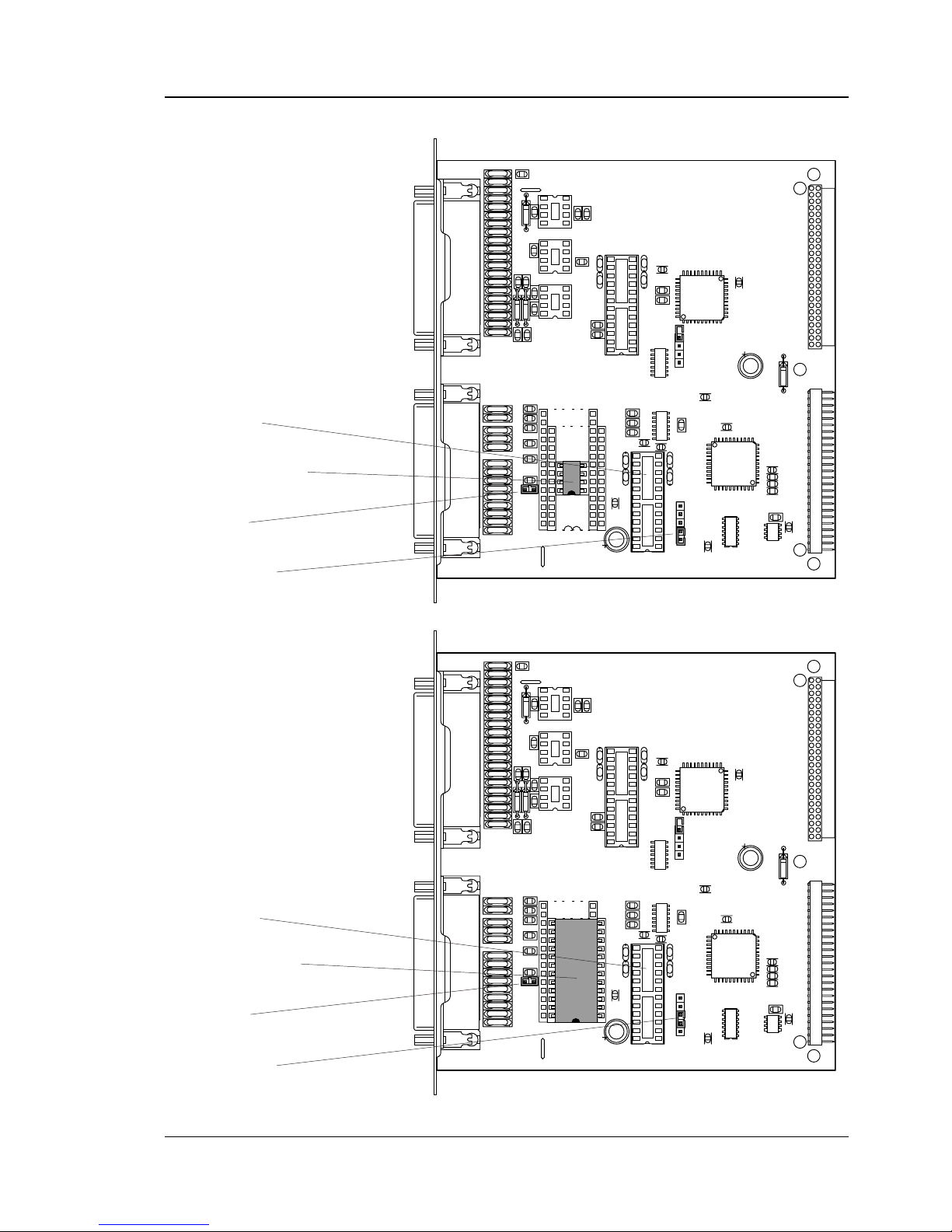
• If necessary, fi t or remove circuits and straps to adapt the
Double Serial Interface Board for the desired type of serial
interface as described in Chapter 3 and 4.
• Insert the Double Serial Interface Board with the components side facing right, as seen from behind. Check that the
board fi ts into the two square cut-outs on the left side of the
slot.
• Attach the Double Serial Interface Board to the printer’s
rear plate by means of two of the screws left ov er when you
removed the original cover plate.
• Using the remaining two screws, attach the narrow cover
plate included in the delivery so it covers the right side of
the slot.
• Connect the cable running from P81 on the CPU board to
connector P1 on the Double Serial Interface Board.
Double Serial Interface Board
EasyCoder 501 XP and
601 XP, cont.
Page 5

EasyCoder XP- & F-Series Double Serial Interface Board – Installation Instructions Ed. 2
4
Chapter 2 Installation
EasyCoder 501 XP and
601 XP, cont.
• Put back the cover over the electronics compartment. Press
fi rmly to compress the leaf springs along the front and rear
edges of the electronics compartment.
• Connect the power cord.
• Now you have two ne w interface connectors on the printer's
rear plate in addition to the standard serial interface "uart1:"
and the standard parallel interface "centronics:". Connect
the interface cables and switch on the power.
• Enter the Setup Mode to set the proper baud rate, character
length, parity, number of stop bits, fl owcontrol, new line,
and buffer size parameters for the new serial ports "uart2:"
and "uart3:".
Serial Interface
"uart3:"
Serial Interface
"uart2:"
Serial Interface
"uart1:"
Centronics Interface
"centronics:"
Page 6

5
EasyCoder XP- & F-Series Double Serial Interface Board – Installation Instructions Ed. 2
Chapter 2 Installation
• Open the electronics compartment by removing the front/
left-hand cover, which is held by three #T20 Torx screws
from the media compartment side of the center section.
Warning!
Switch off the power and disconnect the power cord. The
electronics compartment contains high voltag e components
and wires. Do not open the electronics compartment before
the printer is safely disconnected from any AC supply.
• Remove the two #T10 Torx screws that hold the interface
cover plate on the printer’s rear plate. Remove the cover
plate.
• Save the cover plate for possible later use. Keep the
screws.
EasyCoder F2 and F4
#T10 T orx screw
Cover Plate
#T10 T orx screw
#T20 Torx screws (x3)
Page 7

EasyCoder XP- & F-Series Double Serial Interface Board – Installation Instructions Ed. 2
6
Chapter 2 Installation
EasyCoder F2 and F4,
cont.
• If necessary, fi t or remove circuits and straps to adapt the
Double Serial Interface Board for the desired type of serial
interfaces as described in Chapter 3 and 4.
• Insert the interface board with the components side facing
right, as seen from behind.
• Attach the interface board to the printer’s rear plate by
means of the two screws left over when you removed the
original cover plate.
• Connect the fl at cable included in the kit between connector
P81 on the CPU board and connector P1 on the interface
board (also see the next page.)
P35
IC305
P32
IC304
P33
P81
P1
C7
R12
R15
R14
R13
R9
R8
R3
R2
R1
JP1
IC7
IC6
IC5
IC2
IC1
C15
C14
C13
C12
C11
C6
RP1
C5
C4
C3
C2
C1
C10
D1
F1
F2
F3
F4
F5
F6
F7
F8
F9
F10
F11
F12
F13
F14
IC3IC4
IC18
JP2
P1
P2
P3
P4
R4
R5
R6
R7
R11
R10
RS422nonisol.: IC18, S1,S4
S3
+
+
+
+
S1
S2
S4
RS232: IC2
RS422isolated: IC3, S2, S4
RS485: IC4, S3, S4*
* Term. if end of cable
C8
C9
R20
R21
R23
R22
R30
R35
R33
R32
R34
R31
R26
R28
R25R24
R27
R29
IC15
D2
IC10
F32
F24
F20
F23
RP2
F31
F34
F16
F17
F18
F25
F33
F30
IC12
IC13
IC14
IC11
C119
C18
C17
C16
+
+
+
JP3
S5
S6
1-971613-00.A01
UART3
UART2
20mA CL: IC13, IC14, S6
RS232: IC11
RS422nonisol.: IC12, S5
* Term. if end of cable
RS485: IC4, S3, S4*
RS422isolated: IC3, S2, S4
RS232: IC2
RS422nonisol.: IC18, S1,S4
Interface
Board
Page 8

7
EasyCoder XP- & F-Series Double Serial Interface Board – Installation Instructions Ed. 2
Chapter 2 Installation
EasyCoder F2 and F4,
cont.
• Make sure that the cable between CPU board and interface
board runs as illustrated below.
• Put back the cover over the electronics compartment.
• Connect the power cord.
• Now you have two new interface connectors on the print-
er’s rear plate in addition to the standard interfaces "uart1:"
and "usb1:". Connect the interface cables and switch on the
power.
• Enter the Setup Mode to set the proper baud rate, character
length, parity, number of stop bits, fl owcontrol, new line,
and buffer size parameters for the new serial ports "uart2:"
and "uart3:".
Serial Interface
"uart2:"
Serial Interface
"uart1:"
CPU Board
Interface Board
Cable
Serial Interface
"uart3:"
Serial Interface
"usb1:"
Page 9

EasyCoder XP- & F-Series Double Serial Interface Board – Installation Instructions Ed. 2
8
Chapter 3
C7
R12
R15
R14
R13
R9
R8
R3
R2
R1
JP1
IC7
IC6
IC5
IC2
IC1
C15
C14
C13
C12
C11
C6
RP1
C5
C4
C3
C2
C1
C10
D1
F1
F2
F3
F4
F5
F6
F7
F8
F9
F10
F11
F12
F13
F14
IC3IC4
IC18
JP2
P1
P2
P3
P4
R4
R5
R6
R7
R11
R10
RS422nonisol.: IC18, S1,S4
S3
+
+
+
+
S1
S2
S4
RS232: IC2
RS422isolated: IC3, S2, S4
RS485: IC4, S3, S4*
* Term. if end of cable
C8
C9
R20
R21
R23
R22
R30
R35
R33
R32
R34
R31
R26
R28
R25R24
R27
R29
IC15
D2
IC10
F32
F24
F20
F23
RP2
F31
F34
F15
F16
F17
F18
F25
F33
F30
IC12
IC13
IC14
IC11
C119
C18
C17
C16
+
+
+
JP3
S5
S6
1-971613-00.A01
UART3
UART2
20mA CL: IC13, IC14, S6
RS232: IC11
RS422nonisol.: IC12, S5
* Term. if end of cable
RS485: IC4, S3, S4*
RS422isolated: IC3, S2, S4
RS232: IC2
RS422nonisol.: IC18, S1,S4
Fit RS-232 circuit on IC2
No circuits on IC3, IC4, or IC18
Strap on S4 deactivated
(fi tted on one pin only)
Strap on S1 deactivated
(fi tted on one pin only)
Serial Port Confi guration "uar t2:"
The serial communication port "uart2:" can be confi gured for
one of four different types of serial communication:
• RS-232
• RS-422 non isolated
• RS-422 isolated
• RS-485
By fi tting or removing certain circuits and straps, the desired
type of interface can be selected. This is either done at factory
or by the customer. There can only be one dri v er circuit and its
corresponding straps fi tted at a time.
Caution!
When fi tting circuits yourself, do it befor e connecting the interface board and make sure that the circuits are not fi tted upside
down (see front end markings in the illustrations in this chapter.) Also take care so all “legs” of the circuits fi t into their
respective slots in the socket and are not bent. Also, take
proper pr ecautions so as to protect the board and circuits fr om
electrostatic discharges.
Introduction
RS-232
Page 10
9
EasyCoder XP- & F-Series Double Serial Interface Board – Installation Instructions Ed. 2
Chapter 3 Serial Port Confi guration "uart2:"
RS-422 Non Isolated
C7
R12
R15
R14
R13
R9
R8
R3
R2
R1
JP1
IC7
IC6
IC5
IC2
IC1
C15
C14
C13
C12
C11
C6
RP1
C5
C4
C3
C2
C1
C10
D1
F1
F2
F3
F4
F5
F6
F7
F8
F9
F10
F11
F12
F13
F14
IC3IC4
IC18
JP2
P1
P2
P3
P4
R4
R5
R6
R7
R11
R10
RS422nonisol.: IC18, S1,S4
S3
+
+
+
+
S1
S2
S4
RS232: IC2
RS422isolated: IC3, S2, S4
RS485: IC4, S3, S4*
* Term. if end of cable
C8
C9
R20
R21
R23
R22
R30
R35
R33
R32
R34
R31
R26
R28
R25R24
R27
R29
IC15
D2
IC10
F32
F24
F20
F23
RP2
F31
F34
F15
F16
F17
F18
F25
F33
F30
IC12
IC13
IC14
IC11
C119
C18
C17
C16
+
+
+
JP3
S5
S6
1-971613-00.A01
UART3
UART2
20mA CL: IC13, IC14, S6
RS232: IC11
RS422nonisol.: IC12, S5
* Term. if end of cable
RS485: IC4, S3, S4*
RS422isolated: IC3, S2, S4
RS232: IC2
RS422nonisol.: IC18, S1,S4
No circuit on IC2
Fit RS-422 circuit on IC18
Fit strap on S4
Fit strap on S1 only
No circuit on IC2
Fit RS-422 circuit on IC3
Fit strap on S4
Fit strap on S2 only
RS-422 Isolated
Page 11

EasyCoder XP- & F-Series Double Serial Interface Board – Installation Instructions Ed. 2
10
Chapter 3 Serial Port Confi guration "uart2:"
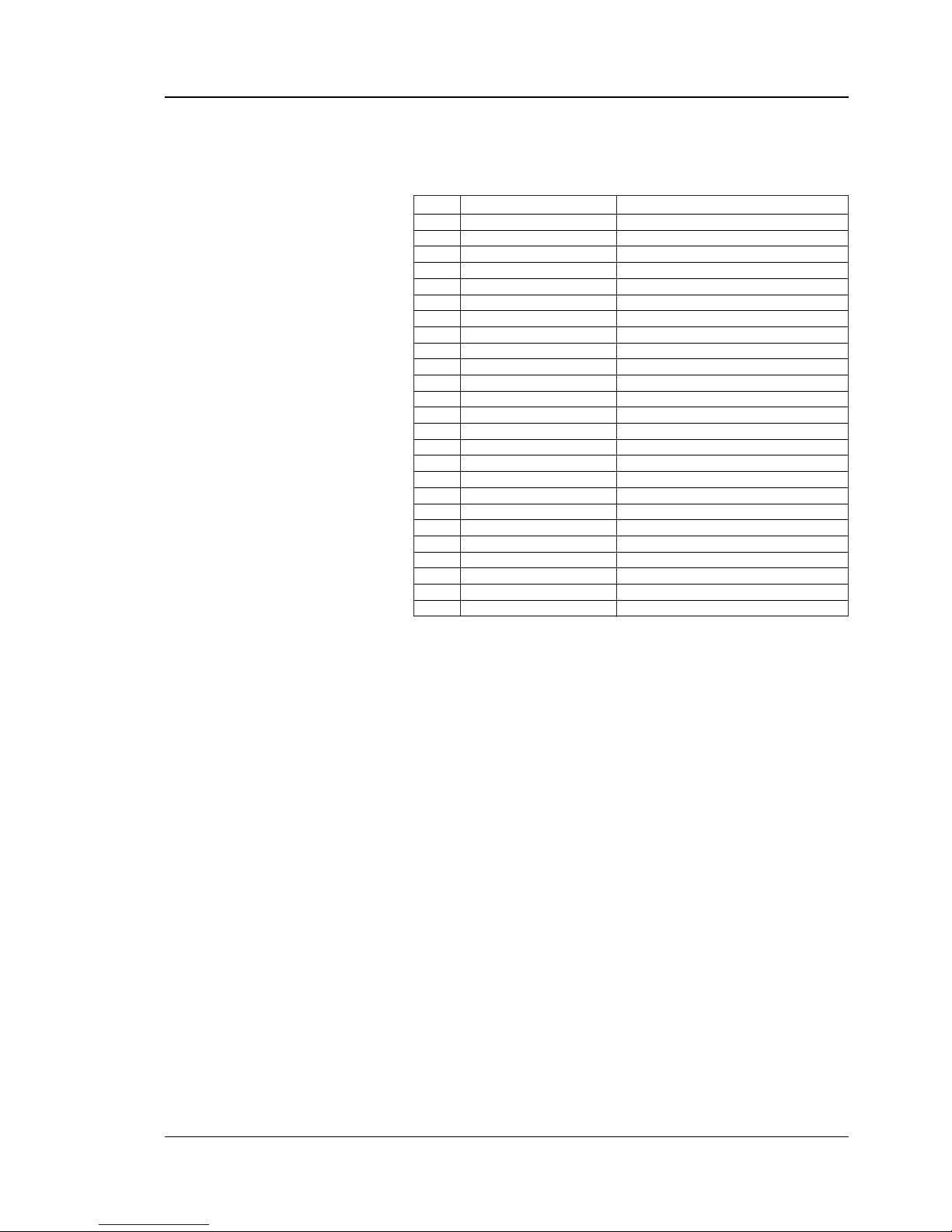
Connector Confi gura-
tion
The serial interface for "uart2:" uses a female DB-25pin connector.
Pin Signal Name Description
1 Not connected
2 TxD RS-232 Transmitter
3 RxD RS-232 Receiver
4 RTS RS-232 Request To Send
5 CTS RS-232 Clear To Send
6 DSR RS-232 Data Set Ready
7 GND Ground
8–14 Not connected
15 +RS422RI +RS-422 Receive
16 +5V 5 Volt for external use (max. 200 mA)
1
17 -RS422RI - RS-422 Receive
18 Not connected
19 +RS422DO + RS-422 Transmit/+ RS-485
20 DTR RS-232 Data Terminal Ready
21 -RS422DO - RS-422 Transmit/- RS-485
22 RI RS-232 Ring Indicator
23 Shield Optional shield for RS-422 and RS-485
24–25 Not connected
1
/. The external 5V is automatically switched off at overload.
C7
R12
R15
R14
R13
R9
R8
R3
R2
R1
JP1
IC7
IC6
IC5
IC2
IC1
C15
C14
C13
C12
C11
C6
RP1
C5
C4
C3
C2
C1
C10
D1
F1
F2
F3
F4
F5
F6
F7
F8
F9
F10
F11
F12
F13
F14
IC3IC4
IC18
JP2
P1
P2
P3
P4
R4
R5
R6
R7
R11
R10
RS422nonisol.: IC18, S1,S4
S3
+
+
+
+
S1
S2
S4
RS232: IC2
RS422isolated: IC3, S2, S4
RS485: IC4, S3, S4*
* Term. if end of cable
C8
C9
R20
R21
R23
R22
R30
R35
R33
R32
R34
R31
R26
R28
R25R24
R27
R29
IC15
D2
IC10
F32
F24
F20
F23
RP2
F31
F34
F15
F16
F17
F18
F25
F33
F30
IC12
IC13
IC14
IC11
C119
C18
C17
C16
+
+
+
JP3
S5
S6
1-971613-00.A01
UART3
UART2
20mA CL: IC13, IC14, S6
RS232: IC11
RS422nonisol.: IC12, S5
* Term. if end of cable
RS485: IC4, S3, S4*
RS422isolated: IC3, S2, S4
RS232: IC2
RS422nonisol.: IC18, S1,S4
RS-485
No circuit on IC2
Fit RS-485 circuit on IC4
Fit strap on S4 if end of cable
Fit strap on S3 only
Page 12

11
EasyCoder XP- & F-Series Double Serial Interface Board – Installation Instructions Ed. 2
Chapter 4
Serial Port Confi guration "uar t3:"
Introduction
The serial communication port "uart3:" can be confi gured for
one of three different types of serial communication:
• RS-232
• RS-422 non isolated
• 20 mA current loop
By fi tting or removing certain circuits and straps, the desired
type of interface can be selected. This is either done at factory
or by the customer.
Caution!
When fi tting circuits yourself, do it before connecting the inter-
face board and make sure that the circuits are not fi tted upside
down (see front end markings in the illustrations in this chapter.) Also take care so all “legs” of the circuits fi t into their
respective slots in the socket and are not bent. Also, take
proper pr ecautions so as to protect the board and circuits fr om
electrostatic discharges.
C7
R12
R15
R14
R13
R9
R8
R3
R2
R1
JP1
IC7
IC6
IC5
IC2
IC1
C15
C14
C13
C12
C11
C6
RP1
C5
C4
C3
C2
C1
C10
D1
F1
F2
F3
F4
F5
F6
F7
F8
F9
F10
F11
F12
F13
F14
IC3IC4
IC18
JP2
P1
P2
P3
P4
R4
R5
R6
R7
R11
R10
RS422nonisol.: IC18, S1,S4
S3
+
+
+
+
S1
S2
S4
RS232: IC2
RS422isolated: IC3, S2, S4
RS485: IC4, S3, S4*
* Term. if end of cable
C8
C9
R20
R21
R23
R22
R30
R35
R33
R32
R34
R31
R26
R28
R25R24
R27
R29
IC15
D2
IC10
F32
F24
F20
F23
RP2
F31
F34
F15
F16
F17
F18
F25
F33
F30
IC12
IC13
IC14
IC11
C119
C18
C17
C16
+
+
+
JP3
S5
S6
1-971613-00.A01
UART3
UART2
20mA CL: IC13, IC14, S6
RS232: IC11
RS422nonisol.: IC12, S5
* Term. if end of cable
RS485: IC4, S3, S4*
RS422isolated: IC3, S2, S4
RS232: IC2
RS422nonisol.: IC18, S1,S4
No circuits on IC12, IC13, or IC14
RS-232 circuit fi tted on IC11
Strap on S5/S6 deactivated
(fi tted on one pin only)
RS-232
Page 13

EasyCoder XP- & F-Series Double Serial Interface Board – Installation Instructions Ed. 2
12
Chapter 4 Serial Port Confi guration "uart3:"
RS-422 Non Isolated
No circuits on IC13 and IC14
Fit RS-422 circuit on IC12
Remove circuit on IC11
Fit strap on S5
C7
R12
R15
R14
R13
R9
R8
R3
R2
R1
JP1
IC7
IC6
IC5
IC2
IC1
C15
C14
C13
C12
C11
C6
RP1
C5
C4
C3
C2
C1
C10
D1
F1
F2
F3
F4
F5
F6
F7
F8
F9
F10
F11
F12
F13
F14
IC3IC4
IC18
JP2
P1
P2
P3
P4
R4
R5
R6
R7
R11
R10
RS422nonisol.: IC18, S1,S4
S3
+
+
+
+
S1
S2
S4
RS232: IC2
RS422isolated: IC3, S2, S4
RS485: IC4, S3, S4*
* Term. if end of cable
C8
C9
R20
R21
R23
R22
R30
R35
R33
R32
R34
R31
R26
R28
R25R24
R27
R29
IC15
D2
IC10
F32
F24
F20
F23
RP2
F31
F34
F15
F16
F17
F18
F25
F33
F30
IC12
IC13
IC14
IC11
C119
C18
C17
C16
+
+
+
JP3
S5
S6
1-971613-00.A01
UART3
UART2
20mA CL: IC13, IC14, S6
RS232: IC11
RS422nonisol.: IC12, S5
* Term. if end of cable
RS485: IC4, S3, S4*
RS422isolated: IC3, S2, S4
RS232: IC2
RS422nonisol.: IC18, S1,S4
Fit circuits on IC13 and IC14
No circuit on IC12
Remove circuit on IC11
Fit strap on S6
20 mA Current Loop
Page 14
13
EasyCoder XP- & F-Series Double Serial Interface Board – Installation Instructions Ed. 2
Chapter 4 Serial Port Confi guration "uart3:"
The serial interface for "uart3:" uses a male DB-25pin connector.
Pin Signal Name Description
1 Not connected
2 TxD RS-232 Transmitter
3 RxD RS-232 Receiver
4 RTS RS-232 Request To Send
5 CTS RS-232 Clear To Send
6 DSR RS-232 Data Set Ready
7 GND Ground
8 Not connected
9 +20M1 + 20 mA current loop
10 -20M1 - 20 mA current loop
1 1 +TXD + TXD 20 mA current loop
12 -TXD - TXD 20 mA current loop
13 +20M2 + 20 mA current loop (printer active receiver)
14 -20M2 - 20 mA current loop (printer active receiver)
15 +RS422I + RS-422 Receive
16 +5V 5 Volt for external use (max. 200 mA)
1
17 -RS422I - RS-422 Receive
18 +RxD + TXD 20 mA current loop
19 +RS422O/+RS 485 + RS-422 Transmit/+RS 485
20 DTR RS-232 Data Terminal Ready
21 -RS422O/-RS485 - RS-422 Transmit/-RS 485
22 RI RS-232 Ring Indicator
23 Shield Optional shield for RS-422
24 Not connected
25 -RxD - TXD 20 mA current loop
1
/. The external 5V is automatically switched off at overload.
Connector Confi gura-
tion
Page 15

EasyCoder XP- & F-Series Double Serial Interface Board – Installation Instructions Ed. 2
14
Notes
 Loading...