

Page 1

RT1700 Radio Data Terminal
USER’S GUIDE
" " " " " " " " " " " " " " " " " " " " " " " " " " " "
PN: 961-047-068
Revision A
May 1997
Page 2

" NOTICE This publicationcontains information proprietary to Intermec Technologies Corporation. It is
being supplied to you with the express understanding that the information contained herein is
for the benefit ofthe contracting party only,andmay not be copied, distributed, or displayedto
third parties without the express written consent of Intermec Technologies Corporation, and
shall be returned to the Corporation upon written request. If a purchase, license, or
nondisclosure agreement has been executed, the terms of that agreement shall govern this
document.
This publication is furnishedfor information only,and the information initis subject to change
without notice. Although every effort has been made to provide complete and accurate
information, the Corporation assumes no responsibility or liability for any errors or
inaccuracies that may appear in this document.
Wewelcomeyourcomments concerning this publication.Although every effort has beenmade
to keep itfree of errors, some may occur.When reporting a specific problem, please describe it
briefly and include the book title and part number,as well as the paragraph or figure number
and the page number.
Send your comments to:
Publications Department
Intermec Technologies Corporation
Norand Mobile Systems Division
550 Second Street SE
Cedar Rapids, IA 52401
Telephone(319) 369-3100
Faxsimile (319) 369-3453
Ò Registered trademark; Marca Registrada byIntermec TechnologiesCorporation,CedarRapids,
Iowa, U.S.A.
ä
Trademark, Intermec Technologies Corporation, Cedar Rapids, Iowa, U.S.A.
Ó Copyright 1994 Intermec Technologies Corporation. All rights reserved.
This publication printed on recycled paper.
Page 3

CONTENTS
" " " " " " " " " " " " " " " " " " " " " " " " " " " "
SECTION 1
General Information 1-1. . . . . . . . . . . . . . . . . . . . . . . . . . . . . . . . . . . . . .
Introduction 1-1. . . . . . . . . . . . . . . . . . . . . . . . . . . . . . . . . . . . . . . . . . . . . . .
Unpacking and Inspecting 1-3. . . . . . . . . . . . . . . . . . . . . . . . . . . . . . . . . . . .
TerminalDescription 1-3. . . . . . . . . . . . . . . . . . . . . . . . . . . . . . . . . . . . . . . .
Keyboard 1-3. . . . . . . . . . . . . . . . . . . . . . . . . . . . . . . . . . . . . . . . . . . . . .
Display 1-5. . . . . . . . . . . . . . . . . . . . . . . . . . . . . . . . . . . . . . . . . . . . . . .
Display Annunciators (messages) 1-5. . . . . . . . . . . . . . . . . . . . . . . . . . .
Annunciator Screen Position 1-8. . . . . . . . . . . . . . . . . . . . . . . . . . . . . . .
TerminalBuzzer 1-10. . . . . . . . . . . . . . . . . . . . . . . . . . . . . . . . . . . . . . . .
Scanner Connector 1-10. . . . . . . . . . . . . . . . . . . . . . . . . . . . . . . . . . . . . .
Charger Connector and Communication Port 1-10. . . . . . . . . . . . . . . . . .
Backlight 1-12. . . . . . . . . . . . . . . . . . . . . . . . . . . . . . . . . . . . . . . . . . . . . .
Battery Compartment 1-12. . . . . . . . . . . . . . . . . . . . . . . . . . . . . . . . . . . .
Battery Pack 1-12. . . . . . . . . . . . . . . . . . . . . . . . . . . . . . . . . . . . . . . . . . .
Handstrap 1-12. . . . . . . . . . . . . . . . . . . . . . . . . . . . . . . . . . . . . . . . . . . . .
Internal Memory 1-13. . . . . . . . . . . . . . . . . . . . . . . . . . . . . . . . . . . . . . . .
ETS Display Annunciators 1-14. . . . . . . . . . . . . . . . . . . . . . . . . . . . . . . . . . . .
SECTION 2
Terminal Operation 2-1. . . . . . . . . . . . . . . . . . . . . . . . . . . . . . . . . . . . . . .
Introduction 2-1. . . . . . . . . . . . . . . . . . . . . . . . . . . . . . . . . . . . . . . . . . . . . . .
Preparation 2-1. . . . . . . . . . . . . . . . . . . . . . . . . . . . . . . . . . . . . . . . . . . . . . . .
Battery Pack Installation 2-2. . . . . . . . . . . . . . . . . . . . . . . . . . . . . . . . . . . . . .
Charging the Battery Pack in the Terminal 2-4. . . . . . . . . . . . . . . . . . . .
Backlight Operation 2-5. . . . . . . . . . . . . . . . . . . . . . . . . . . . . . . . . . . . . . . . .
RT1700 Radio Data Terminal User’s Guide i
Page 4

CONTENTS "
Options 2-6. . . . . . . . . . . . . . . . . . . . . . . . . . . . . . . . . . . . . . . . . . . . . . . . . . .
Electrostatic Safe Environment 2-7. . . . . . . . . . . . . . . . . . . . . . . . . . . . .
Radio Module Removal 2-7. . . . . . . . . . . . . . . . . . . . . . . . . . . . . . . . . .
Installing Modules 2-10. . . . . . . . . . . . . . . . . . . . . . . . . . . . . . . . . . . . . .
SST Radio Module Replacement 2-11. . . . . . . . . . . . . . . . . . . . . . . . . . . . . . .
TerminalInstallation 2-14. . . . . . . . . . . . . . . . . . . . . . . . . . . . . . . . . . . . . . . . .
TerminalOperation 2-15. . . . . . . . . . . . . . . . . . . . . . . . . . . . . . . . . . . . . . . . . .
Turning the TerminalOn 2-15. . . . . . . . . . . . . . . . . . . . . . . . . . . . . . . . . .
Turning the TerminalOff 2-16. . . . . . . . . . . . . . . . . . . . . . . . . . . . . . . . .
Attaching a Bar Code Scanner 2-16. . . . . . . . . . . . . . . . . . . . . . . . . . . . . . . . .
SECTION 3
Menu Screens 3-1. . . . . . . . . . . . . . . . . . . . . . . . . . . . . . . . . . . . . . . . . . . .
Introduction 3-1. . . . . . . . . . . . . . . . . . . . . . . . . . . . . . . . . . . . . . . . . . . . . . .
Keyboard Functions 3-1. . . . . . . . . . . . . . . . . . . . . . . . . . . . . . . . . . . . .
Gold ( ) and Black ( ) Shift Keys 3-1. . . . . . . . . . . . . . . . . . . . . . . . . .
[ENTER] Key 3-1. . . . . . . . . . . . . . . . . . . . . . . . . . . . . . . . . . . . . . . . . .
Numeric Keys ([0] through [9]) 3-1. . . . . . . . . . . . . . . . . . . . . . . . . . . .
Y Up and B Down Arrows 3-2. . . . . . . . . . . . . . . . . . . . . . . . . . . . . . .
Setting the Terminal Operating Parameters 3-3. . . . . . . . . . . . . . . . . . . . . . .
Opening the Main Menu 3-3. . . . . . . . . . . . . . . . . . . . . . . . . . . . . . . . . .
Set-Up Parms 3-5. . . . . . . . . . . . . . . . . . . . . . . . . . . . . . . . . . . . . .
LCD Parms 3-5. . . . . . . . . . . . . . . . . . . . . . . . . . . . . . . . . . . . . . . .
Beeper Setup 3-6. . . . . . . . . . . . . . . . . . . . . . . . . . . . . . . . . . . . . . .
Tests 3-6. . . . . . . . . . . . . . . . . . . . . . . . . . . . . . . . . . . . . . . . . . . . .
Version Info 3-6.. . . . . . . . . . . . . . . . . . . . . . . . . . . . . . . . . . . . . . .
Exit Menus 3-6. . . . . . . . . . . . . . . . . . . . . . . . . . . . . . . . . . . . . . . .
More 3-6.. . . . . . . . . . . . . . . . . . . . . . . . . . . . . . . . . . . . . . . . . . . .
Opening the Set-Up Parms Menu 3-7. . . . . . . . . . . . . . . . . . . . . . . . . . .
57-Key Standard Terminal 3-7. . . . . . . . . . . . . . . . . . . . . . . . . . . .
37-Key Terminal Special Instructions 3-7. . . . . . . . . . . . . . . . . . . .
Radio # 3-9. . . . . . . . . . . . . . . . . . . . . . . . . . . . . . . . . . . . . . . . . . .
Bar Code Parms 3-13. . . . . . . . . . . . . . . . . . . . . . . . . . . . . . . . . . . .
Scanner Type 3-13. . . . . . . . . . . . . . . . . . . . . . . . . . . . . . . . . . . . . . .
Scan Options 3 -14. . . . . . . . . . . . . . . . . . . . . . . . . . . . . . . . . . . . . . .
Scan Options (1) 3-15. . . . . . . . . . . . . . . . . . . . . . . . . . . . . . . . . . . .
Scan Options (2) 3-18. . . . . . . . . . . . . . . . . . . . . . . . . . . . . . . . . . . .
Lengths Options 3-20. . . . . . . . . . . . . . . . . . . . . . . . . . . . . . . . . . . .
ii RT1700 Radio Data Terminal User’s Guide
Page 5

CONTENTS "
Protocol Options 3-22. . . . . . . . . . . . . . . . . . . . . . . . . . . . . . . . . . . . . . . .
Host View Size 3-23. . . . . . . . . . . . . . . . . . . . . . . . . . . . . . . . . . . . .
Data Stream 3-23. . . . . . . . . . . . . . . . . . . . . . . . . . . . . . . . . . . . . . . .
Extended CMDS 3-24. . . . . . . . . . . . . . . . . . . . . . . . . . . . . . . . . . . .
5250 Options 3-25. . . . . . . . . . . . . . . . . . . . . . . . . . . . . . . . . . . . . . .
3270 Options 3-26. . . . . . . . . . . . . . . . . . . . . . . . . . . . . . . . . . . . . . .
3210 Emulation 3-27. . . . . . . . . . . . . . . . . . . . . . . . . . . . . . . . . . . . .
VT220 3-27. . . . . . . . . . . . . . . . . . . . . . . . . . . . . . . . . . . . . . . . . . . .
Native (F1 is Func-0) 3-29. . . . . . . . . . . . . . . . . . . . . . . . . . . . . . . .
Display Options 3-29. . . . . . . . . . . . . . . . . . . . . . . . . . . . . . . . . . . . . . . .
Backlight 3-30.. . . . . . . . . . . . . . . . . . . . . . . . . . . . . . . . . . . . . . . . .
Cursor Mode 3-31. . . . . . . . . . . . . . . . . . . . . . . . . . . . . . . . . . . . . . .
Remote Display 3-31. . . . . . . . . . . . . . . . . . . . . . . . . . . . . . . . . . . . .
Radio Comm 3-32.. . . . . . . . . . . . . . . . . . . . . . . . . . . . . . . . . . . . . . . . . .
Cold Start 3-33. . . . . . . . . . . . . . . . . . . . . . . . . . . . . . . . . . . . . . . . . . . . .
LCD Parms (Parameters) 3-34. . . . . . . . . . . . . . . . . . . . . . . . . . . . . . . . . . . . .
LCD Contrast 3-35. . . . . . . . . . . . . . . . . . . . . . . . . . . . . . . . . . . . . . . . . .
Screen Size 3-36. . . . . . . . . . . . . . . . . . . . . . . . . . . . . . . . . . . . . . . . . . . .
Screen Mode 3-37. . . . . . . . . . . . . . . . . . . . . . . . . . . . . . . . . . . . . . . . . . .
Backlight 3-39. . . . . . . . . . . . . . . . . . . . . . . . . . . . . . . . . . . . . . . . . . . . . .
Key Uppercase 3-39. . . . . . . . . . . . . . . . . . . . . . . . . . . . . . . . . . . . . . . . .
Scroll Window 3-40. . . . . . . . . . . . . . . . . . . . . . . . . . . . . . . . . . . . . . . . .
Beeper Setup 3-40. . . . . . . . . . . . . . . . . . . . . . . . . . . . . . . . . . . . . . . . . . . . . . .
Key Click 3-41. . . . . . . . . . . . . . . . . . . . . . . . . . . . . . . . . . . . . . . . . . . . .
Error Tone 3-42. . . . . . . . . . . . . . . . . . . . . . . . . . . . . . . . . . . . . . . . . . . . .
Beeper Select 3-42. . . . . . . . . . . . . . . . . . . . . . . . . . . . . . . . . . . . . . . . . .
Tests 3-43. . . . . . . . . . . . . . . . . . . . . . . . . . . . . . . . . . . . . . . . . . . . . . . . . . . . .
Peripherals 3-43. . . . . . . . . . . . . . . . . . . . . . . . . . . . . . . . . . . . . . . . . . . .
Radio Test 3-44. . . . . . . . . . . . . . . . . . . . . . . . . . . . . . . . . . . . . . . . .
RS232 Test 3-44. . . . . . . . . . . . . . . . . . . . . . . . . . . . . . . . . . . . . . . .
Display Test 3-46. . . . . . . . . . . . . . . . . . . . . . . . . . . . . . . . . . . . . . .
Keyboard Test 3-47. . . . . . . . . . . . . . . . . . . . . . . . . . . . . . . . . . . . . .
Scanner Test 3-47. . . . . . . . . . . . . . . . . . . . . . . . . . . . . . . . . . . . . . .
Memory View 3-48. . . . . . . . . . . . . . . . . . . . . . . . . . . . . . . . . . . . . . . . . .
Packet Driver Test 3-48. . . . . . . . . . . . . . . . . . . . . . . . . . . . . . . . . . . . . . .
Link Test (UHF only) 3-49. . . . . . . . . . . . . . . . . . . . . . . . . . . . . . . .
Link Watch (UHF only) 3-49. . . . . . . . . . . . . . . . . . . . . . . . . . . . . .
Packet Stats 3-50. . . . . . . . . . . . . . . . . . . . . . . . . . . . . . . . . . . . . . . .
Histogram Opts 3-51. . . . . . . . . . . . . . . . . . . . . . . . . . . . . . . . . . . . . . . . .
Numbers 3-52.. . . . . . . . . . . . . . . . . . . . . . . . . . . . . . . . . . . . . . . . . . . . .
RT1700 Radio Data Terminal User’s Guide iii
Page 6

CONTENTS "
Version Info (Information) 3-52. . . . . . . . . . . . . . . . . . . . . . . . . . . . . . . . . . . .
Exit Menus 3-53. . . . . . . . . . . . . . . . . . . . . . . . . . . . . . . . . . . . . . . . . . . . . . . .
More 3-53.. . . . . . . . . . . . . . . . . . . . . . . . . . . . . . . . . . . . . . . . . . . . . . . . . . . .
Keyboard Opts (Options) 3-53. . . . . . . . . . . . . . . . . . . . . . . . . . . . . . . . .
Save Parms 3-54. . . . . . . . . . . . . . . . . . . . . . . . . . . . . . . . . . . . . . . . . . . .
Cloning Opts 3-55. . . . . . . . . . . . . . . . . . . . . . . . . . . . . . . . . . . . . . . . . . .
Session Menu 3-56. . . . . . . . . . . . . . . . . . . . . . . . . . . . . . . . . . . . . . . . . .
SECTION 4
Maintenance and
Troubleshooting 4-1. . . . . . . . . . . . . . . . . . . . . . . . . . . . . . . . . . . . . . . . . .
Introduction 4-1. . . . . . . . . . . . . . . . . . . . . . . . . . . . . . . . . . . . . . . . . . . . . . .
TerminalMaintenance 4-1. . . . . . . . . . . . . . . . . . . . . . . . . . . . . . . . . . . . . . .
Battery Pack Maintenance 4-1. . . . . . . . . . . . . . . . . . . . . . . . . . . . . . . .
Case Maintenance 4-2. . . . . . . . . . . . . . . . . . . . . . . . . . . . . . . . . . . . . . .
Cleaning Up Liquid Spills 4-3.. . . . . . . . . . . . . . . . . . . . . . . . . . . . . . .
Removing Accumulated Dirt And Grime 4-3. . . . . . . . . . . . . . . . . . . . .
Handstrap Maintenance 4-4. . . . . . . . . . . . . . . . . . . . . . . . . . . . . . . . . .
Troubleshooting the Terminal 4-5. . . . . . . . . . . . . . . . . . . . . . . . . . . . . . . . . .
Power-up Screen 4 -5. . . . . . . . . . . . . . . . . . . . . . . . . . . . . . . . . . . . . . . .
Troubleshooting Procedures 4-5.. . . . . . . . . . . . . . . . . . . . . . . . . . . . . .
APPENDIX A
Specifications A-1.. . . . . . . . . . . . . . . . . . . . . . . . . . . . . . . . . . . . . . . . . . .
Introduction A-1. . . . . . . . . . . . . . . . . . . . . . . . . . . . . . . . . . . . . . . . . . . . . . .
TerminalSpecifications A-1. . . . . . . . . . . . . . . . . . . . . . . . . . . . . . . . . . . . . .
Physical A-1. . . . . . . . . . . . . . . . . . . . . . . . . . . . . . . . . . . . . . . . . . . . . . .
Size: A-1. . . . . . . . . . . . . . . . . . . . . . . . . . . . . . . . . . . . . . . . . . . . .
Weight: A-1. . . . . . . . . . . . . . . . . . . . . . . . . . . . . . . . . . . . . . . . . . .
Environmental Characteristics A-1. . . . . . . . . . . . . . . . . . . . . . . . .
Temperature: A-1. . . . . . . . . . . . . . . . . . . . . . . . . . . . . . . . . . . . . . .
Humidity: A-1. . . . . . . . . . . . . . . . . . . . . . . . . . . . . . . . . . . . . . . . .
Altitude: A-1. . . . . . . . . . . . . . . . . . . . . . . . . . . . . . . . . . . . . . . . . .
Radio Characteristics A-2. . . . . . . . . . . . . . . . . . . . . . . . . . . . . . . . . . . .
Memory Specifications A-2. . . . . . . . . . . . . . . . . . . . . . . . . . . . . . . . . . .
Battery Pack Characteristics A-2. . . . . . . . . . . . . . . . . . . . . . . . . . . . . . .
Recommended Battery Pack Chargers A-2. . . . . . . . . . . . . . . . . . . . . . .
iv RT1700 Radio Data Terminal User’s Guide
Page 7

CONTENTS "
Communications Interfaces A-2. . . . . . . . . . . . . . . . . . . . . . . . . . . . . . . .
Model Numbers A-3. . . . . . . . . . . . . . . . . . . . . . . . . . . . . . . . . . . . . . . .
Scanner Specifications A-4. . . . . . . . . . . . . . . . . . . . . . . . . . . . . . . . . . . . . . .
Environmental Characteristics A-4. . . . . . . . . . . . . . . . . . . . . . . . . . . . .
Scanner Characteristics A-4. . . . . . . . . . . . . . . . . . . . . . . . . . . . . . .
Reading Conditions A-4. . . . . . . . . . . . . . . . . . . . . . . . . . . . . . . . . .
Depth of Field (DOF) A-4. . . . . . . . . . . . . . . . . . . . . . . . . . . . . . . .
900 MHz Radio Option A-5. . . . . . . . . . . . . . . . . . . . . . . . . . . . . . . . . . . . . .
NIC Specifications A-5. . . . . . . . . . . . . . . . . . . . . . . . . . . . . . . . . . . . . .
Synthesized UHF Radio Option A-6. . . . . . . . . . . . . . . . . . . . . . . . . . . . . . . .
NIC Specifications A-6. . . . . . . . . . . . . . . . . . . . . . . . . . . . . . . . . . . . . .
Proxim 2.4 GHz Radio Option A-7. . . . . . . . . . . . . . . . . . . . . . . . . . . . . . . . .
NIC Specifications A-7. . . . . . . . . . . . . . . . . . . . . . . . . . . . . . . . . . . . . .
Radio and Scanner Modules A-8. . . . . . . . . . . . . . . . . . . . . . . . . . . . . . . . . . .
APPENDIX B
Bar Code Symbologies B-1. . . . . . . . . . . . . . . . . . . . . . . . . . . . . . . . . . . .
Introduction B-1. . . . . . . . . . . . . . . . . . . . . . . . . . . . . . . . . . . . . . . . . . . . . . .
Bar Code Symbology B-3. . . . . . . . . . . . . . . . . . . . . . . . . . . . . . . . . . . . . . . .
UPC B-4. . . . . . . . . . . . . . . . . . . . . . . . . . . . . . . . . . . . . . . . . . . . . . . . .
EAN B-4. . . . . . . . . . . . . . . . . . . . . . . . . . . . . . . . . . . . . . . . . . . . . . . . .
Codabar B-5. . . . . . . . . . . . . . . . . . . . . . . . . . . . . . . . . . . . . . . . . . . . . . .
C11 (Code 11) B-5. . . . . . . . . . . . . . . . . . . . . . . . . . . . . . . . . . . . . . . . . .
C39 B-6. . . . . . . . . . . . . . . . . . . . . . . . . . . . . . . . . . . . . . . . . . . . . . . . . .
Extended Code 39 (Concatenation) B-6. . . . . . . . . . . . . . . . . . . . . . . . .
Encoded Code 39 (Full ASCII) B-6. . . . . . . . . . . . . . . . . . . . . . . . . . . . .
C93 B-7. . . . . . . . . . . . . . . . . . . . . . . . . . . . . . . . . . . . . . . . . . . . . . . . . .
C128 B-7. . . . . . . . . . . . . . . . . . . . . . . . . . . . . . . . . . . . . . . . . . . . . . . . .
2 of 5 (Straight 2 of 5) B-9. . . . . . . . . . . . . . . . . . . . . . . . . . . . . . . . . . .
I 2 of 5 B-10. . . . . . . . . . . . . . . . . . . . . . . . . . . . . . . . . . . . . . . . . . . . . . . .
CI 2 Of 5 B-10.. . . . . . . . . . . . . . . . . . . . . . . . . . . . . . . . . . . . . . . . . . . . .
Plessey B-11.. . . . . . . . . . . . . . . . . . . . . . . . . . . . . . . . . . . . . . . . . . . . . .
RT1700 Radio Data Terminal User’s Guide v
Page 8

CONTENTS "
APPENDIX C
Keyboard Overlays C-1. . . . . . . . . . . . . . . . . . . . . . . . . . . . . . . . . . . . . . .
General Information C-1. . . . . . . . . . . . . . . . . . . . . . . . . . . . . . . . . . . . . . . . .
APPENDIX D
Connectors and Pin Definitions D-1. . . . . . . . . . . . . . . . . . . . . . . . . . . .
APPENDIX E
Scanner Instructions E-1. . . . . . . . . . . . . . . . . . . . . . . . . . . . . . . . . . . . . .
Introduction E-1. . . . . . . . . . . . . . . . . . . . . . . . . . . . . . . . . . . . . . . . . . . . . . .
Setting Up The Terminal E-1. . . . . . . . . . . . . . . . . . . . . . . . . . . . . . . . . . . . . .
Using The Integrated Scanner E-2. . . . . . . . . . . . . . . . . . . . . . . . . . . . . . . . . .
APPENDIX F
Battery Indicators F-1. . . . . . . . . . . . . . . . . . . . . . . . . . . . . . . . . . . . . . . .
Introduction F-1.. . . . . . . . . . . . . . . . . . . . . . . . . . . . . . . . . . . . . . . . . . . . . .
TypesOf Indicators F-1. . . . . . . . . . . . . . . . . . . . . . . . . . . . . . . . . . . . . . . . . .
Charging Indicators F-1. . . . . . . . . . . . . . . . . . . . . . . . . . . . . . . . . . . . . . . . .
APPENDIX G
Module Reference G-1. . . . . . . . . . . . . . . . . . . . . . . . . . . . . . . . . . . . . . . .
Introduction G-1. . . . . . . . . . . . . . . . . . . . . . . . . . . . . . . . . . . . . . . . . . . . . . .
Adapter Boards G-2. . . . . . . . . . . . . . . . . . . . . . . . . . . . . . . . . . . . . . . . . . . . .
APPENDIX H
Reference Material and Product Accessories H-1. . . . . . . . . . . . . . .
Reference Material H-1. . . . . . . . . . . . . . . . . . . . . . . . . . . . . . . . . . . . . . . . . .
Product Accessories H-2. . . . . . . . . . . . . . . . . . . . . . . . . . . . . . . . . . . . . . . . .
vi RT1700 Radio Data Terminal User’s Guide
Page 9

CONTENTS "
FIGURES
Figure 1-1, Keyboard 1-4. . . . . . . . . . . . . . . . . . . . . . . . . . . . . . . . . . . . . . . .
Figure 1-2, Annunciator Screen Positions 1-8. . . . . . . . . . . . . . . . . . . . . . . .
Figure 1-3, RT1700 Radio Data Terminal 1-11. . . . . . . . . . . . . . . . . . . . . . . .
Figure 2-1, Handstrap Removal 2-2. . . . . . . . . . . . . . . . . . . . . . . . . . . . . . . .
Figure 2-2, Battery Pack Installation 2 -3. . . . . . . . . . . . . . . . . . . . . . . . . . . .
Figure 2-3, Battery Charger to Terminal Connection 2-4. . . . . . . . . . . . . . . .
Figure 2-4, Options 2 -6. . . . . . . . . . . . . . . . . . . . . . . . . . . . . . . . . . . . . . . . . .
Figure 2-5, Hand Strap Removal 2-7. . . . . . . . . . . . . . . . . . . . . . . . . . . . . . .
Figure 2-6, Radio Terminal Major Parts 2-8. . . . . . . . . . . . . . . . . . . . . . . . . .
Figure 2-7, Module Removal 2-9. . . . . . . . . . . . . . . . . . . . . . . . . . . . . . . . . .
Figure 2-8, Module Installation 2-10. . . . . . . . . . . . . . . . . . . . . . . . . . . . . . . .
Figure 2-9, CPU Board, Interconnect Board Alignment 2-12. . . . . . . . . . . . . .
Figure 2-10, RM40/50/80/90 Radio Modules 2-13. . . . . . . . . . . . . . . . . . . . . .
Figure 2-11,Connect Tethered Scanner 2-16. . . . . . . . . . . . . . . . . . . . . . . . . .
Figure 4-1, Handstrap Removal 4-4. . . . . . . . . . . . . . . . . . . . . . . . . . . . . . . .
Figure C-1, Native Keyboard Overlay C-2. . . . . . . . . . . . . . . . . . . . . . . . . . .
Figure C-2, 5250 Keyboard Overlay C-3.. . . . . . . . . . . . . . . . . . . . . . . . . . .
Figure C-3, 3270 Keyboard Overlay C-4.. . . . . . . . . . . . . . . . . . . . . . . . . . .
Figure C-4, VT220 Keyboard Overlay C-5. . . . . . . . . . . . . . . . . . . . . . . . . . .
Figure C-5, 37-Key Keyboard Overlay C-6. . . . . . . . . . . . . . . . . . . . . . . . . .
Figure D-1, Connector End View D-1. . . . . . . . . . . . . . . . . . . . . . . . . . . . . . .
Figure D-2, Connector Pinouts D-1. . . . . . . . . . . . . . . . . . . . . . . . . . . . . . . . .
Figure D-3, Locking 6-Pin Connector (Optional) D-2. . . . . . . . . . . . . . . . . . .
Figure D-4, Surface Contact Pin Descriptions D-2. . . . . . . . . . . . . . . . . . . . .
Figure E-1, Scanner WarningLabels E-3. . . . . . . . . . . . . . . . . . . . . . . . . . . .
Figure E-2, Radio Frequency Terminal E-4. . . . . . . . . . . . . . . . . . . . . . . . . .
Figure G-1, Adaptor Boards G-2. . . . . . . . . . . . . . . . . . . . . . . . . . . . . . . . . . .
Figure G-2, Installing Adaptor Boards G-3. . . . . . . . . . . . . . . . . . . . . . . . . . .
RT1700 Radio Data Terminal User’s Guide vii
Page 10

CONTENTS "
viii RT1700 Radio Data Terminal User’s Guide
Page 11

Section 1
General Information
" " " " " " " " " " " " " " " " " " " " " " " " " " " "
Introduction
This user’s guide contains instructions on setting-up, operating, and maintaining the RT1700Radio Data Terminal. The information in this guide is
contained in four sections:
" General Information
" Terminal Operation
" Menu Screens
" Maintenance & Troubleshooting
Appendixes contain:
" Terminal and scanner specifications
" Explanation of bar code symbologies
" List of available keyboard overlays
" Connector pin definitions
" Specifications for scanner operation
" Charging messages and Low Battery indicators
General Information contains a summary of this user’s guide, instructions
on unpacking and inspecting the terminal, and a description of the terminal
components.
Terminal Operation contains instructions on using the terminal, and contains instructions on installing and replacing the radio and scanner modules.
Menu Screens explains how to set operational parameters for the terminal.
Parameter selection depends upon the host system, and how you intend to
use the terminal.
RT1700 Radio Data TerminalUser’s Guide 1-1
Page 12

SECTION 1 " General Information
Maintenance and Troubleshooting explains the care and maintenance necessary for reliable operation.
Appendix A contains technical specifications for your terminal and scanner.
Appendix B contains an explanation of various bar code symbologies.
Appendix C shows keyboard overlays available for the terminal. The
keyboard overlays are operating system specific — the overlay on your terminal is for use with your specific operating system (5250, 3270, VT220,
etc.).
Appendix D contains the connector pin definitions for the 9 pin D-sub
connector, the 6-pin Mini-DIN RS-232 port, and for the surface connector.
Appendix E describes the integrated scanner.
Appendix F provides details on battery and charging messages and
annunciators.
Appendix G contains a radio module/adaptor board cross reference.
Appendix H lists reference material and product accessories available from
Intermec Technologies Corporation Mobile Systems Division.
1-2 RT1700 Radio Data TerminalUser’sGuide
Page 13

Unpacking and Inspecting
The following procedures explain what to do when your terminal arrives,
and what to do if the terminal was damaged in shipping.
1. Remove the terminal from its shipping container and inspect the terminal for damage.
2. If your terminal was damaged in shipping, record the model number,
part number, and serial number of the damaged unit (found on the
back of the terminal, under the handstrap).
3. Report any shipping damage to the carrier who delivered the product.
Contact the Intermec Technologies Corporation Customer Response Center
at 1-800-755-5505 for technical assistance or repair instructions.
Terminal Description
See Figure 1-3 for the location of the components described in the following
paragraphs.
SECTION 1 " General Information
Keyboard
The keyboard (Figure 1-1) has 57 color-coded alphanumeric keys, including
the ON/OFF key. Use the keyboard or a scanner to enter information into
the terminal.
The keyboard has an overlay that is specific to the host computer operating
system. Overlays use graphical and alphanumeric symbols to represent key
functions when the keyboard is in one of the shifted (black or gold) modes.
Press the black or gold key to “shift” the keyboard. The standard keyboard
layout is shown in Figure 1-1.
The keyboard can also be redefined, however, this process is not detailed in
this manual. Instructions for redefining the keyboard can be found in the
5250 Terminal Emulation Programmers Reference Guide, Part Number
977-047-039 or in the VT220/ANSI Terminal Emulation Programmers Reference Guide, Part Number 977-047-037
Appendix C shows keyboard overlays.
RT1700 Radio Data TerminalUser’s Guide 1-3
Page 14

SECTION 1 " General Information
1-4 RT1700 Radio Data TerminalUser’sGuide
Figure 1-1
Keyboard
Page 15

SECTION 1 " General Information
c
Display
The display shows the terminal status, messages from the host computer,
and the keystrokes you make.
The terminal has the following display formats:
Lines Characters Per Line
4 12, 17, 22, or 26
6 12, 17, 22, or 26
8 12, 17, 22, or 26
10 12, 17, 22, or 26
12 12, 17, 22, or 26
16 12, 17, 22, 26, or 31
21 12, 17, 22, or 26
Display Annunciators (messages)
Annunciators (terminal status indicators) appear at the right side of the display. The display annunciators, and their meaning, are:
The terminal is connected to a charging source. Does not necessarily mean the terminal is charging since that is dependent upon battery
state, temperature, and other conditions.
"
NOTE: The symbols above are larger than they appear on the terminal display.
E
Error: The terminal is connected to a charging source, however
charging is not possible. See Appendix F for details.
+
-
Low Battery Annunciator: When the low battery annunciator
appears, you may want to connect the battery pack to a charger as soon as
possible. See Appendix F for detailed charging messages and battery warnings.
"
NOTE: When the terminal shuts down due to a low battery, it will not turn on until the bat-
tery pack is rechargedor is replacedwith a fully charged pack. If you replace the
battery pack, the terminal will retainany data in RAM for up to five minutes with
the battery pack removed. Toensure no data in RAM is lost, install a fully charged
battery pack in the terminal immediately after removing the discharged battery
pack.
RT1700 Radio Data TerminalUser’s Guide 1-5
Page 16

SECTION 1 " General Information
T
X
Transmitting data: The terminal is transmitting data to the host
computer
R
X
Receiving data: The terminal is receiving data.
C
L
Communication Loss: The terminal cannot communicate with the
host computer. The terminal may be out of radio range, the base radio may
not have power, or communication between them may be improperly set up.
Y
Alpha character shift mode: The terminal keyboard is in the
alpha character shift mode—any alpha character keystrokes are entered as
uppercase characters.
A
Black shift mode: The terminal keyboard is in the black shift
mode—keystrokes perform the function shown on the overlay just to the
upper left of the key.
"
Gold Shift Mode: The terminal keyboard is in the gold shift
mode—keystrokes enter the symbol or perform the function shown on the
overlay just to the upper right of the key.
X
Input Inhibited: The keyboard has accepted enough information
for the current input field. If the “key ahead” feature is on, the terminal
stores the keystrokes made after “input inhibited” appears. The host may
also inhibit (lockout) the keyboard upon certain errors or when sending
additional information to the terminal.
^
Insert Mode: Characters are inserted, not overwritten.
B
Line Edit (Block) Mode: The radio terminal is sending to the host
computer, cumulative data when you press a terminating key.
K
Keypad Mode: The keypad is active.
1-6 RT1700 Radio Data TerminalUser’sGuide
Page 17

SECTION 1 " General Information
C
Character Mode: The radio terminal is sending, to the host com-
puter, each keystroke as you press it. This mode is available only in the
VT220/ANSI emulation.
e
Local Edit Mode: This is a feature of the VT330/VT340 terminal.
This mode is available only in the VT220/ANSI emulation.
B
Bad Battery: The battery pack you are currently using is bad.
T
Temperature: The terminal is currently out of the battery charging
temperature range, which is 5° to 40° C.
S
C
A
N
Laser scanner in use: A laser scanner is connected (to the termi-
nal) and is active.
WARNING: Never stare into the beam emitted from a laser scanner. Injury and permanent
damage to the eyes can occur.
RT1700 Radio Data TerminalUser’s Guide 1-7
Page 18

SECTION 1 " General Information
Annunciator Screen Position
Annunciators are located on the extreme right side of your terminal screen,
in 6 separate positions. Each position is 4 pixels by 7 pixels. The following
figure illustrates where each annunciator is positioned.
Position 1
Position 2
Position 3
Position 4
Position 5
Position 6
Annunciator Screen Positions
"
NOTE: Position 1 is actually 14 pixels in height, as opposed to 7 for the other positions.
Figure 1-2
Annunciator Position
T
X
1
R
X
1
C
L
X 2
K 2
1-8 RT1700 Radio Data TerminalUser’sGuide
1
Page 19

SECTION 1 " General Information
Annunciator Position
C 2
e 2
B 2
^
Y
A
"
c 4
E 5
2
3
3
3
B 6
T 6
+
-
S
C
A
N
"
NOTE: All the individual letter annunciators areonly 5 pixels in height, except for the T
(temperature) and the B (bad battery), which are 7 pixels in height.
"
NOTE: The low battery annunciator and the scan annunciator are larger icons, therefore
they take up more than one position.
4, 5, and 6
1, 2, and 3
RT1700 Radio Data TerminalUser’s Guide 1-9
Page 20

SECTION 1 " General Information
Terminal Buzzer
The buzzer sounds when you press a key (the “key click”) or make a good
scan, and when certain error conditions occur. You can adjust the frequency
level and length (duration) for the buzzer tones.
B
CAUTION: The pins on the external connectors of the terminal are fragile. Attach or
disconnect cables with care to prevent damaging the connectors.
Scanner Connector
The scanner connector (bottom of the terminal) is a D-subminiature squeeze
and release connector. This is the standard connector for 5-volt bar code
scanners. The RT1700is only compatible with 5-volt scanners.
Charger Connector and Communication Port
The 6-pin mini-DIN connector on the bottom of the terminal is the battery
charger connector and is also an RS-232 communication port.
1-10 RT1700 Radio Data TerminalUser’sGuide
Page 21

SECTION 1 " General Information
6
5
1
2
3
4
1. Function keys
2. Alpha keys
3. Numeric keys
4. Terminal ID slot
5. ON/OFF key
6. Display
RT1700 Radio Data Terminal
Figure 1-3
RT1700 Radio Data TerminalUser’s Guide 1-11
Page 22

SECTION 1 " General Information
Backlight
A backlight is available to illuminate the display under poor lighting conditions. You can set the amount of time the backlight stays on. The range is
from 1 to 25 seconds, but should be set to the minimum time you really
need. That is because the backlight consumes battery power. The longer
the backlight stays on, the shorter the battery run-time. Instructions for
configuring the backlight can be found on page 3-27.
Battery Compartment
The battery compartment (on the back of the terminal) contains the battery
pack. The battery compartment cover attaches to the terminal case by a
quarter-turn cam lock. A flat blade screwdriver or coin can be used to open
the lock. To open, turn the cam lock 1/4 turn counterclockwise; to close,
turn 1/4 turn clockwise.
Battery Pack
The battery pack has six rechargeable cells, a temperature sensor, and a
side-mounted contact block packaged in a shrink-wrap case. The battery
pack must be installed so the battery pack metal contacts touch the metal
contacts in the battery compartment. Battery packs can be alkaline,
NiMH, or NiCd, and should power the terminal for an average of 10--12
hours of normal use, but this time will vary depending upon the age of the
battery pack, the type of battery pack, and how you use the terminal. For
more information, see Appendix A, Battery Pack Characteristics.
Handstrap
A handstrap, on the back side of the terminal, allows a secure hold on the
terminal. Slipping your hand between the terminal and the handstrap makes
the terminal rest snugly against your hand.
With age, the handstrap will lose its elasticity and should be replaced.
Replacement straps are available from your Intermec sales representative.
1-12 RT1700 Radio Data TerminalUser’sGuide
Page 23

SECTION 1 " General Information
Internal Memory
The RT1700 Series Radio Data Terminal contains two types of internal
memory. One type is called volatile or pseudo-static Random Access
Memory (RAM), and the other type is called Flash Read Only Memory
(ROM).
Any data in RAM is safe (the data will not be lost) as long as the terminal
has power. However, if you remove the battery pack from the terminal for
more than five (5) minutes, or if the terminal battery pack remains in the
terminal in a low power state for 30 days or longer, data in RAM can be
lost. When the low battery icon is on, place the terminal on a charger as
soon as possible—or replace the discharged battery pack with a fullycharged pack.
When replacing the battery pack, the terminal retains RAM data for up to
five minutes with the battery pack removed. It is a good idea to replace the
battery pack with a fully-charged pack immediately after removing the discharged pack.
The flash-ROM is long-term memory,with a capacity of 512 kilobytes.
This is where terminal emulation applications and operating system programs are stored. ROM is not for data storage, and information in ROM
cannot be lost if the battery pack is removed or is left in the terminal in a
discharged condition. ROM can only be erased or rewritten with special
interface cables.
RT1700 Radio Data TerminalUser’s Guide 1-13
Page 24

SECTION 1 " General Information
ETS Display Annunciators
"
NOTE: The following applies only if your terminal is equipped with 7524 Extended Termi-
nal Services (ETS).
The icons shown below are displayed along the right-hand border of the
LCD display to show terminal status on 7524 hand-held terminals only.
C
Communication Loss
L
The terminal is out of range of the base station, or the base or terminal has a
problem with its radio.
T
Terminal is Transmitting
X
R
Terminal is Receiving
X
**
* *
****
****
****
The Keypad is in Caps Lock mode. Press the black shift followed by the
“lock” key (gold shift on handhelds) to clear the Caps Lock mode.
*
**
***
**
*
This indicates the left side (black) shift key has been pressed and the next
keystroke will take the black shifted value.
*
**
***
**
*
This indicates the right side (gold) shift key has been pressed and the next
keystroke will take the gold shifted value.
Caps Lock Mode
Black Shift Selected
Gold Shift Selected
1-14 RT1700 Radio Data TerminalUser’sGuide
Page 25

SECTION 1 " General Information
+
Battery Power Status
n
This indicate the level of battery power in the terminal. The “n” may be a 3,
2, or 1, with 3 being the highest charge and 1 being the lowest charge.
When even less power than a 1 remains, the n becomes a “--”. This indicates that very little battery power remains and the battery should either be
recharged or replaced. The terminal will turn itself off 2 minutes after this
stage is reached.
"
NOTE: Detecting battery power is a very inexact science. As a result, when the terminal is
first poweredon, it will take at least 5 minutes for the terminal to calculate how
much power it has — except for the latest stage; if the battery is extremely low, the
± symbol will be shown right away and the terminal will eventually turn itself off.
**
***
***
The small rectangle which is missing from the overall larger rectangle indicates the part of the virtual display which you can now physically see. The
example shown here indicates that you are viewing the upper left corner of
the virtual display. You cannot window up or left from this point, but you
may be able to move the window down or right if there are more rows or
columns to be seen in those directions.
Scrolling Window Indicator
The top-left corner is the “home base” or origin. If you are in the top row
and the leftmost column, you may or may not have rows below or columns
to the right, that are not currently being displayed. This depends on how the
terminal’sdisplay size has been set up in the menus. However, if the annunciator indicates you are not in the top row,then the display can be scrolled
up one or more times. Likewise, if the annunciator indicates you are not in
the leftmost column, then the display can be moved to the left one or more
times.
RT1700 Radio Data TerminalUser’s Guide 1-15
Page 26

SECTION 1 " General Information
1-16 RT1700 Radio Data TerminalUser’sGuide
Page 27

Section 2
Terminal Operation
" " " " " " " " " " " " " " " " " " " " " " " " " " " "
Introduction
This section contains instructions for setting-up and operating the RT1700
Radio Data Terminal. The section is structured in the following manner:
" Preparation
" Installation
" Operation
" Introduction to the menu screens
Preparation
The following procedures explain how to prepare your new terminal for
operation. Included are instructions for installing and charging the battery
pack.
The battery pack can be installed in the terminal and then charged, or it can
be charged outside the terminal in a charging device. Refer to your battery
care manual for addition information.
Instructions for charging the battery pack outside your terminal come with
the charger. Instructions on charging the battery pack in the terminal follow
the battery installation procedures.
RT1700 Radio Data TerminalUser’s Guide 2-1
Page 28

SECTION 2 " Terminal Operation
Battery Pack Installation
The battery pack is removed from the terminal for shipping. It should also
be removed before the terminal is placed in long-term storage (over 30
days). Fully charge (3 hours) the battery pack before you begin using the
terminal. To install the battery pack in the terminal, refer to the following
instructions.
1. Refer to Figure 2-1. Release the top handstrap retainer (1) by
squeezing the two clips toward each other with your index finger and
thumb on one hand, then push the handstrap retainer out with your
other thumb. Once removed, the handstrap (2) will hang from the
back of the terminal and allow access to the battery compartment.
1
2
3
1. Top handstrap retainer
2. Handstrap
3. Bottom hand strap retainer
Figure 2-1
Handstrap Removal
"
NOTE: Refer to Figure 2-1. Todecrease the pressureon the handstrap retainer, making it
easier to remove, stretchthe handstrap slightly toward the clip before squeezing the
clips together.
2-2 RT1700 Radio Data Terminal User’s Guide
Page 29

SECTION 2 " Terminal Operation
2. Refer to Figure 2-2. Use a small flat blade screwdriver or a coin to
turn the battery cover cam lock (2) counterclockwise approximately
1/4-turn until the screw stops.
3. Lift the battery compartment cover(3) off the terminal case to expose
the battery compartment.
B
CAUTION: The battery pack must be installed contact-side first. Installing the battery pack in
any other manner will damage the battery contacts inside the battery
compartment.
4. When installing the battery pack, insert the contact side of the battery
pack (4) into the battery compartment first. When properly installed,
the metal contacts on the battery pack will match-up with the contacts
inside the battery compartment.
2
3
1
4
1. Radio module
2. Cam lock
3. Battery compartment cover
4. Battery pack
5. Terminal
Figure 2-2
Battery Pack Installation
5
5. Install the battery compartment cover by inserting the guide tabs on
the bottom edge of the cover into the slots on the terminal case. Press
the the cover into the case, then turn the battery cover cam lock
clockwise 1/4 turn.
6. Pull the hand strap snug and flat, and reinstall the top hand strap retainer clip.
RT1700 Radio Data TerminalUser’s Guide 2-3
Page 30

SECTION 2 " Terminal Operation
Charging the Battery Pack in the Terminal
To charge the battery pack while it is in the terminal, do the following:
B
CAUTION: Do NOT remove the battery pack from the terminal with the charging device
connected. Permanent damage to the terminal will occur.
1. Connect an approved charger to the 6-pin mini-DIN connector on the
bottom of the terminal.
From
Battery Charger
Battery Charger to TerminalConnection
2. Plug the charger into a wall outlet supplying the required source voltage for the charger. During the charge cycle, if your terminal is
turned on, the display will show the annunciator icon (C) indicating
the terminal is attached to a charger.
Charging the battery in the terminal takes between 2 and 3-1/2 hours. The
actual time depends on the condition of the battery and the amount of terminal activity during the charge cycle. The battery pack should be recharged
whenever the low battery icon appears on the display.
2-4 RT1700 Radio Data Terminal User’s Guide
Figure 2-3
Page 31

Backlight Operation
The backlight illuminates the display in poor lighting conditions. It can
stay on up to four minutes (you can adjust this time) after the most recent
key press, before automatically shutting off. If the backlight turns off
because of terminal inactivity (when you have not pressed a key recently) it
comes back on the next time you press a key.
To turn the backlight ON, press the gold ( ) shift key,then the backlight symbol ( ) key. Repeating the process turns it off. For more
information on configuring the backlight, see page 3-27.
SECTION 2 " Terminal Operation
RT1700 Radio Data TerminalUser’s Guide 2-5
Page 32
SECTION 2 " Terminal Operation
RADIOMODULE
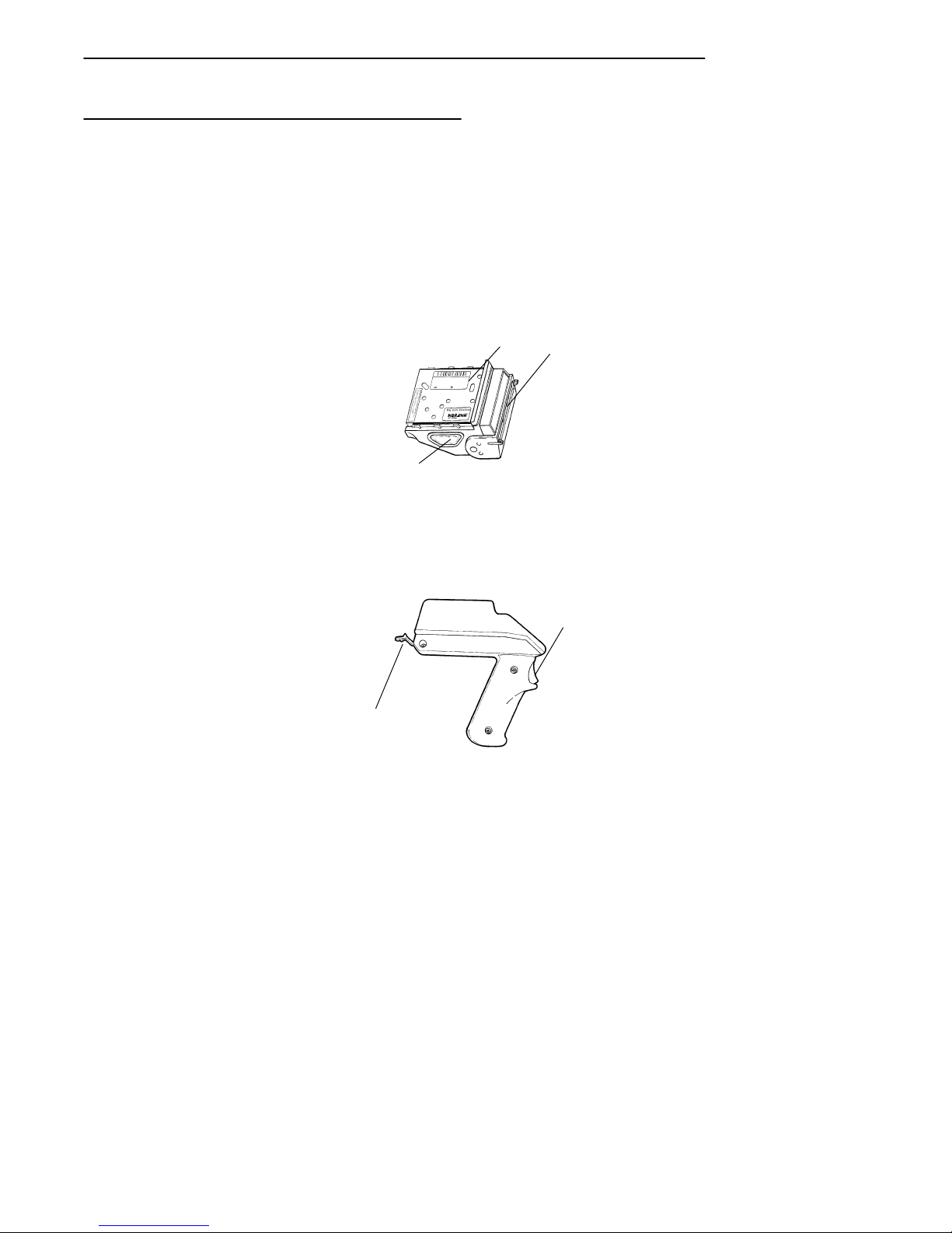
Options
You can change the radio module or you can replace it with an “integrated”
radio and bar code scanner module. A convenient handle can be attached to
the terminal. The handle has a trigger that actuates the integrated scanner. A
tethered scanner can be connected to the 9-pin D-sub connector on the bottom of the terminal.
WITH INTEGRATED SCANNER
1
3
1. Radio
2. Scanner window
3. Scan button(s)
2
2-6 RT1700 Radio Data Terminal User’s Guide
HANDLE ACCESSORY
(holds terminal, actuates scanner)
1
2
1. Scan trigger
2. Terminal retainer
Figure 2-4
Options
Page 33
SECTION 2 " Terminal Operation
Electrostatic Safe Environment
The following steps should be taken to provide an electrostatic safe environment for your data terminal.
" Whenever possible, perform all work on a metal countertop.
" Because of the sensitive nature of electronic components, do not walk
across carpet while holding any part of your radio terminal. Completely reassemble your terminal before leaving your work station.
" Avoid touching any exposed electronic components on your terminal
module.
" Avoid touching the exposed connector pins on the radio module.
For customers doing large volume module replacements; we advise installing an electrostatic safe workplace for this type of procedure.
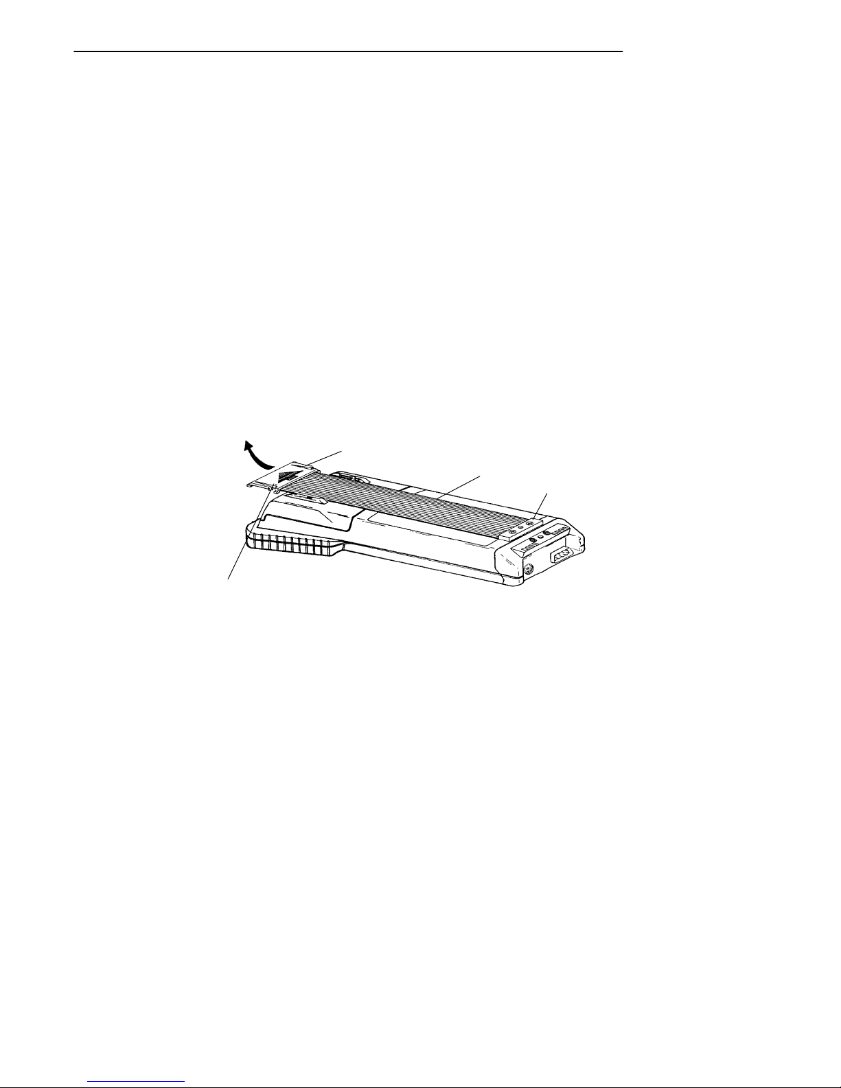
Radio Module Removal
To remove the radio module from the terminal:
1
2
3
Press in on both
sides to release
1. Top handstrap clip
2. Handstrap
3. Bottom handstrap fastener
Figure 2-5
Hand Strap Removal
1. Squeeze the hand strap clips, and slide the top hand strap clip out of
the retaining brackets. (See Figure 2-5)
RT1700 Radio Data TerminalUser’s Guide 2-7
Page 34
SECTION 2 " Terminal Operation
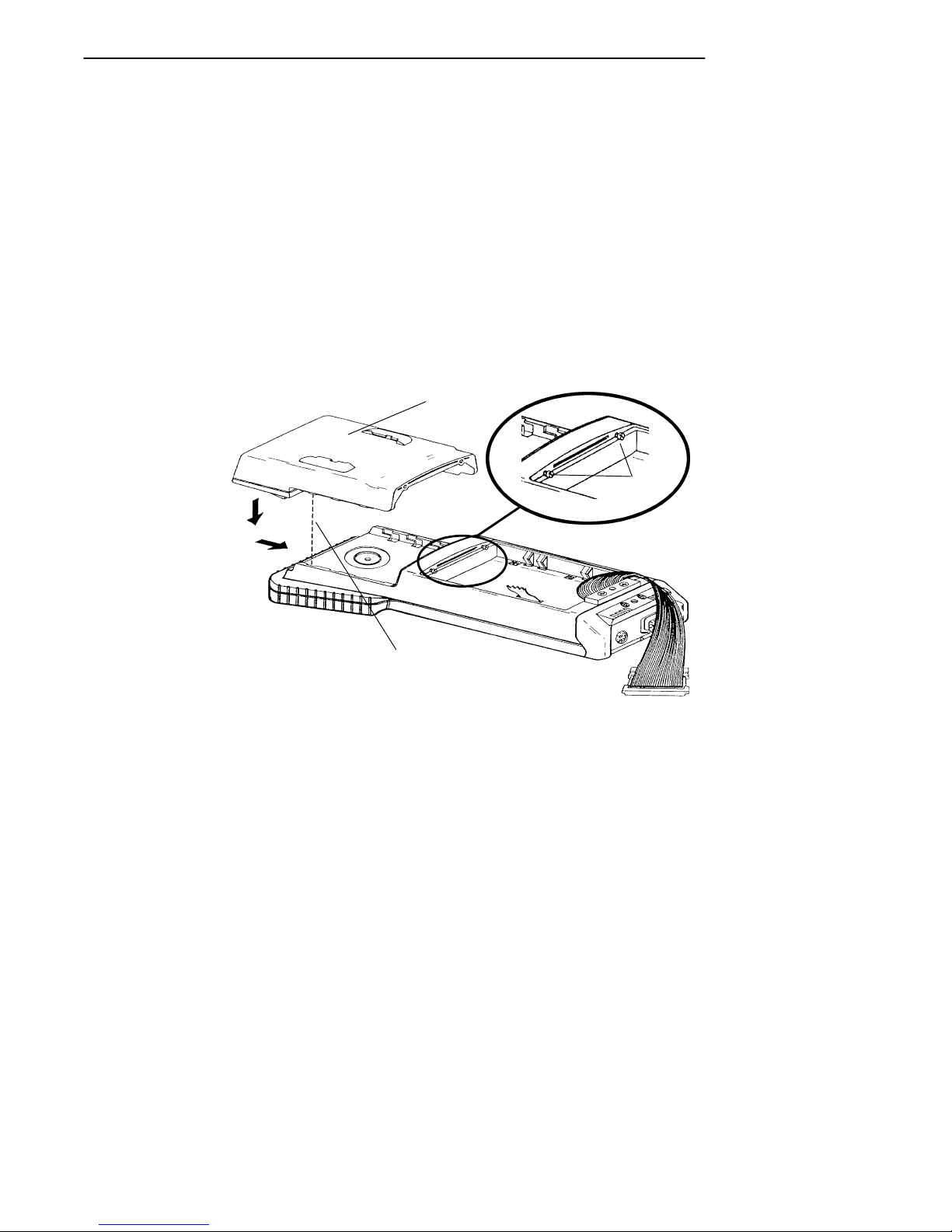
2. Remove the battery compartment cover by turning the cam lock
counterclockwise 1/4 turn.
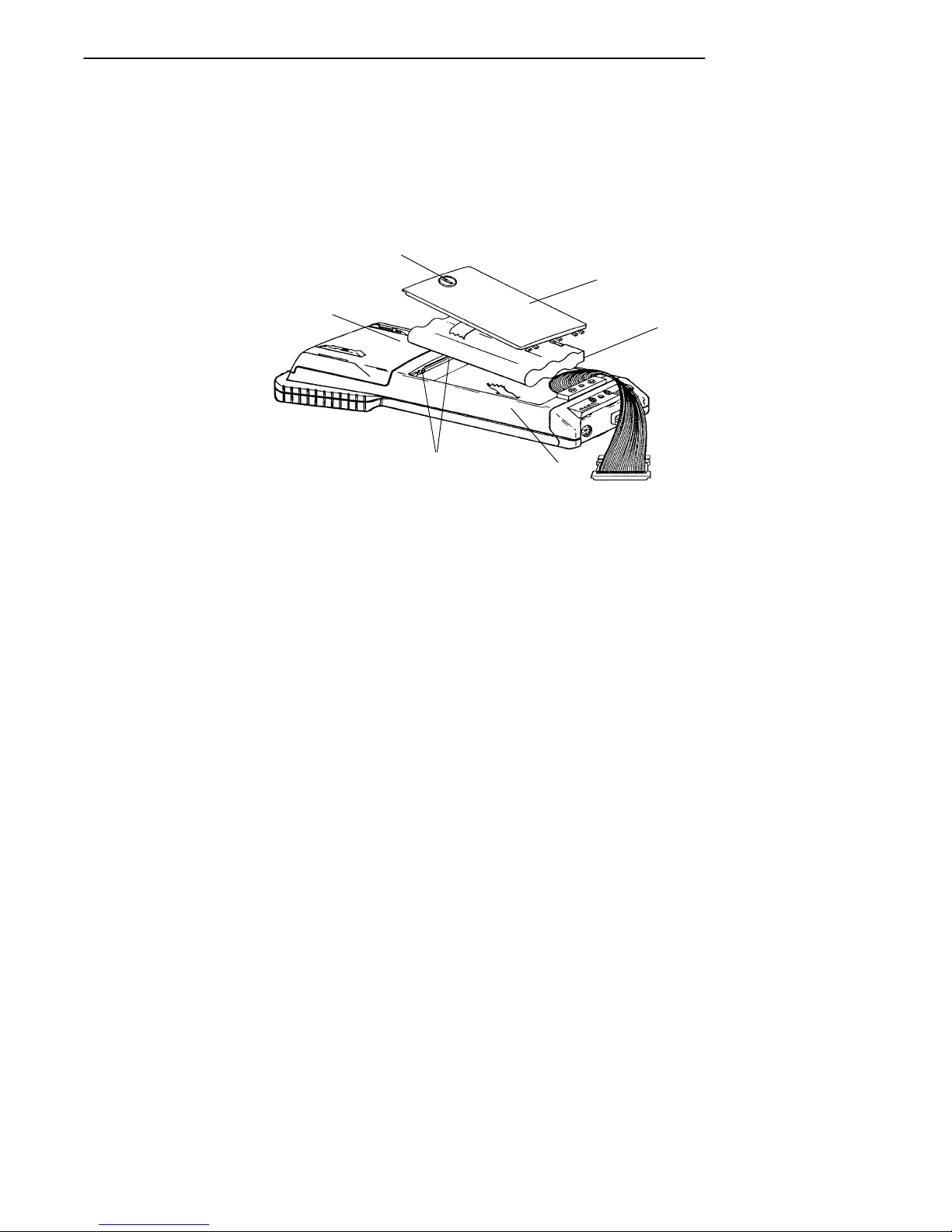
3. Remove the battery pack. (See Figure 2-6)
2
3
1
4
4. Loosen the two Phillips retaining screws located inside the battery
compartment (see Figure 2-6). These screws secure the radio module
to the terminal module. The screws remain attached to the terminal
after they have disengaged the module.
5. Place the terminal face down on your work surface.
6. Grasp the terminal module with one hand and the radio module with
your other hand.
7. Bear down slightly on the radio module, while gently pulling it
straight out, then up and away from the terminal module (see
Figure 2-7).
2-8 RT1700 Radio Data Terminal User’s Guide
5
1. Radio Module
2. Cam lock
3. Battery compartment cover
4. Battery pack
5. Retaining screws
6. Terminal
Figure 2-6
Radio Terminal Major Parts
6
Page 35
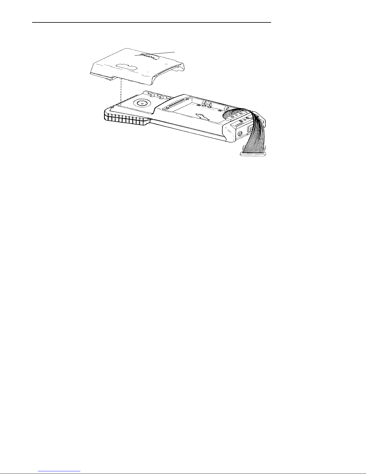
SECTION 2 " Terminal Operation
RADIO MODULE
Figure 2-7
Module Removal
RT1700 Radio Data TerminalUser’s Guide 2-9
Page 36
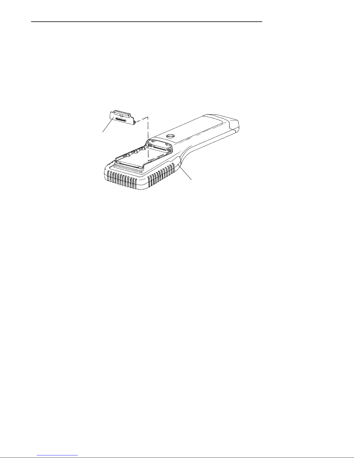
SECTION 2 " Terminal Operation
1
Installing Modules
Follow the instructions in the previous paragraphs on Radio Module
Removal to loosen the handstrap and remove the battery pack:
1. Refer to Figure 2-8. The two retaining screws (2) inside the battery
compartment should already be loosened. If not, make sure that they
are.
2. Lower the module (1) into place and slide it toward the bottom of the
terminal until it fits snugly into place.
3. Be sure to tighten the module retaining screws (2) before reinstalling
the battery pack and the hand strap.
2
Align notches,
slide module
into terminal.
2-10 RT1700 Radio Data Terminal User’s Guide
1. Module
2. Retaining screws (for module)
Figure 2-8
Module Installation
Page 37

SECTION 2 " Terminal Operation
SST Radio Module Replacement
These instruction cover replacing:
" RM40 and RM80 Radio Modules with interconnect board
" RM50 and RM90 Radio Modules with Standard, Long Range (LR),
or Vehicle Identification Number (VIN) Integrated Scanning
WARNING: Standard range scanners are Class II laser products. These products emit less
than one milliwatt of laser light from the output window. No controls are
provided for operation or maintenance. Laser light in excess of Class II limits
the inside internal protective cover. Do not stare into beam if protective cover is
removed.
WARNING: Long range and VIN scanners are Class IIIa laser products. These products
emit a 5.0 milliwatt beam of laser light from the output window. No controls
are provided for operation or maintenance. Laser light in excess of Class II is
present inside the internal protective cover. DO NOT stare into beam if
protective cover is removed.
Your choice of radio module will determine which interface board is
required. The part numbers are:
" RM40 SST radio module with interconnect board, part number
705-280-001.
" RM50 SST radio with integrated scanning interconnect board, part
number 705-281-001.
" RM80 SST radio module with interconnect board, part number
705-318-001.
" RM90 SST radio with integrated scanning interconnect board, part
number 705-319-001.
"
NOTE: If the terminal already has an interconnect board and you are replacingwith the
same model radio module, you do not need this procedure.
Refer back to the instructions for removing the radio module and replace
with your new radio module.
Inserting the interconnect board requires some extra care to ensure you get a
proper fit. Follow the illustrations and the steps carefully to ensure success
with this procedure.
RT1700 Radio Data TerminalUser’s Guide 2-11
Page 38
SECTION 2 " Terminal Operation
1. Hold the terminal with the opening on top and towards you. Line up
the interconnect board so it is positioned with the pins facing away
from you. (See Figure 2-9)
2. Slide the interconnect board into the recessed opening of the component cover on the host board.
3. Gently wiggle the board side to side to start it into the connector.
1
2
1. Adapter board
2. Terminal
CPU Board, Interconnect Board Alignment
"
NOTE: Before you push the board firmly into place, visually ensure that both rowsof pins
on the board fit into the connector, and that the notch on the interconnect board will
clear, but set tight against the plastic boss on the radio terminal.
Figure 2-9
When installed properly,the interconnect board fits flush against the CPU
board in your terminal. The pins on the interconnect board fit all the way
into the connector when completed.
B
CAUTION: If you remove the interconnect board, BE CAREFUL! Do not use pliers to grab
the black alignment handle. This board fits in very tightly,by design.
2-12 RT1700 Radio Data Terminal User’s Guide
Page 39
SECTION 2 " Terminal Operation
B
CAUTION: To remove, firmly grab both sides of the handle and wiggle it side to side while
pulling out. It is helpful to use a small flat blade screwdriver, being careful to lift
up with the same amount of pressure on both sides, to ensure you do not bend or
break off the pins. If you need help, contact our Customer Response Center.
4. Gently slide the new radio module into place.
"
NOTE: The terminal case has three alignment blocks on each side for securing the radio
module into place. Hold the radio module at an angle to help in sliding this module
into position. When finished sliding it into place, the radio module will fit securely
onto the interconnect boardconnector.
5. Tightenthe two Phillips screws to secure the module to the terminal
module.
6. Reinstall the battery pack and the battery compartment cover. Be sure
that the battery door tether strap is positioned around the battery
pack, and then into the battery compartment.
7. While pressing the hand strap release clips, slide the hand strap clip
into the retaining brackets. Be sure the clips snap into place.
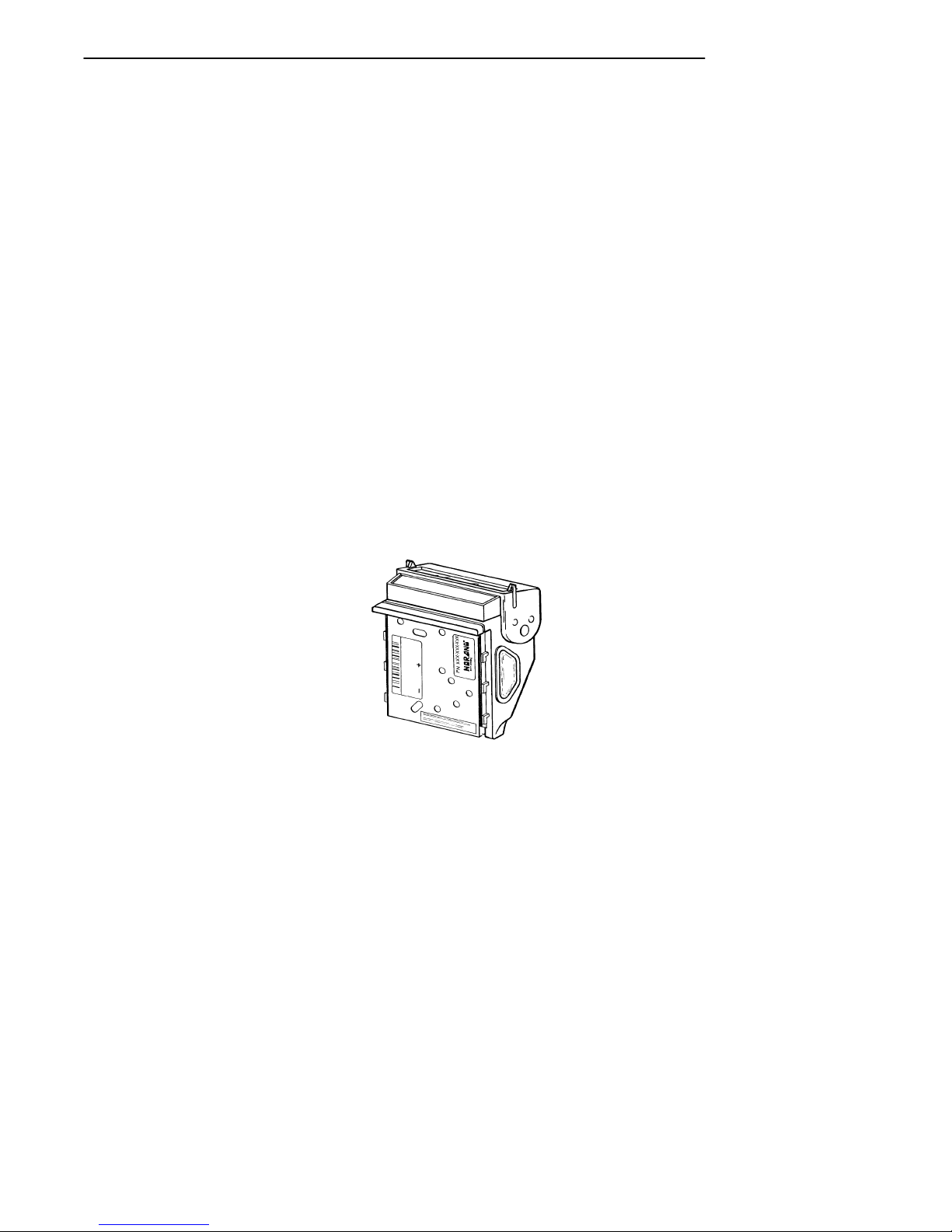
8. The RM40, RM50, RM80, and RM90 radio modules (see
Figure 2-10) contain an internal antenna. If the module you are
replacing had an external antenna, you do not need to replace it.
RM40/50/80/90 Radio Modules
Figure 2-10
RT1700 Radio Data TerminalUser’s Guide 2-13
Page 40

SECTION 2 " Terminal Operation
Terminal Installation
There are no special installation procedures for the RT1700 Radio Data
Terminal. If you have performed the following, your terminal is ready for
use:
" Installed all components of the radio data network including the Base
Radio Transceiver(s), the Network Controller(s), and all necessary
power supplies.
" Installed system software on the host computer, and programmed all
operating parameters required by the software.
" Programmed the operating parameters of the terminal (described in
Section 3 of this guide).
If you have accomplished all of the above, and the host computer does
not recognize (or acknowledge) your terminal, refer to the Maintenance
and Troubleshooting Section of this guide. If the steps provided in the
Maintenance and Troubleshooting Section do not resolve the problem,
contact our Customer Response Center at: 1-800-755-5505.
Programming the Flash ROM
Programming the terminal ROM requires a special cable. The cable connects the round mini-DIN connector on the bottom of the terminal to the
RS-232 communication port on the host computer. You can also connect
one RT1700terminal to another to clone (copy) parameter settings or application programs.
" For computers with a 9-pin RS-232 port use download cable
part number: 216-806-001.
" For computers with a 25-pin RS-232 port, use download cable
part number 216-824-001.
" For cloning parameters or an application from one terminal to anoth-
er, use cloning cable part number 216-909-001.
2-14 RT1700 Radio Data Terminal User’s Guide
Page 41
Terminal Operation
Turning the Terminal On
Turn the terminal on by pressing and releasing the [ON/OFF] key, located
on the terminal keyboard. Each time it is turned on, the terminal displays
several messages in fairly rapid succession. The first message shows the
firmware version and its release date (DD/MM/YY):
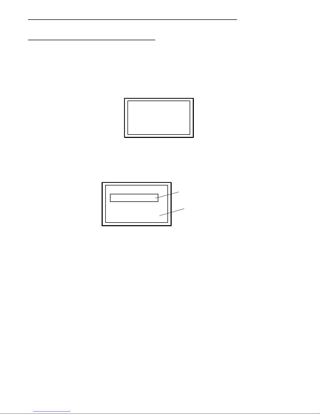
This screen is followed by two more screens that display the firmware name
and version, emulation (host or operating system) type and the unit (terminal) identification number. When session switching is supported, the second
line in the screen below shows the session number.
SECTION 2 " Terminal Operation
FWP170X0 Vx.xx
of DDMMYY
COPR. 1991-1998
INTERMEC.ALL
RIGHTS RESERVED
FWP170X0 Vx.xx
Session: #
Host:
(emulation) ###
ACTIVE SESSION
NUMBER
TERMINAL
ID
NUMBER
Specific terminal operating procedures (how data is entered into the terminal, screens that appear on the terminal display,etc.) depend on the parameters programmed into the terminal and the software controlling your network. Ask your system administrator for additional information.
Turning the Terminal Off
Turn the terminal OFF by pressing and releasing the [ON/OFF] key once.
There will be a momentary delay before the terminal goes off.
RT1700 Radio Data TerminalUser’s Guide 2-15
Page 42

SECTION 2 " Terminal Operation
Attaching a Bar Code Scanner
The RT1700 Radio Data Terminal can be equipped with an integrated scanner, or it can be connected to a variety of tethered 5-volt bar code scanners. Scanners allow the terminal to read and interpret active (enabled) bar
code symbologies.
The tethered bar code scanner attaches to the terminal at the 9-pin D-sub
connector located on the bottom of the terminal. All scanners are powered
by the terminal.
Refer to the documentation you received with your bar code scanner for
instructions on using it.
1
Connect
scanner
here.
2-16 RT1700 Radio Data Terminal User’s Guide
2
1. Typical scanner
2. 9-pin D-sub connector
Figure 2-11
Connect Tethered Scanner
Page 43

Section 3
Menu Screens
" " " " " " " " " " " " " " " " " " " " " " " " " " " "
Introduction
This section describes the menus available to you to set the operating and
scanner parameters for the terminal. Additional information can be found in
the programmer’s guide and technical overview for your particular operating system.
Keyboard Functions
Some keys on the terminal have special functions, which can vary depending upon the application software. General function keys (keys that perform
the same task, regardless of the application) are described in the following
paragraphs.
Gold ( ) and Black ( ) Shift Keys
Use the gold ( ) and black ( ) shift keys to put the keyboard in the
desired (gold or black) shift mode. These shifted key functions are shown
on the keyboard overlays in Appendix C.
[ENTER] Key
Press the [ENTER] key to select an option in the menu shown on the display. This either restores the display to the previous menu or advances to
the next menu in the sequence. You can also press the [ENTER] key several times to return the display to the Main Menu.
Numeric Keys ([0] through [9])
Many menus have numbered options. To choose a particular option, press
the numeric key that corresponds to the option.
RT1700 Radio Data TerminalUser’s Guide 3-1
Page 44

SECTION 3 " Menu Screens
If the menu remains visible, the choice will be darkened. This means that
option is turned on or enabled, and you can select additional options from
the same menu.
To deselect an enabled option, press the number corresponding to that option.
In some cases, pressing a number to make a selection brings up a different
menu (submenu). This allows you to further modify the choice made in the
parent menu. Press the [ENTER] key to confirm the settings and exit this
menu.
After the modification(s), you may (depending on the menu and function)
be permitted to return to the parent menu to make additional selections.
There are also situations where pressing (6) causes the terminal to Exit from
of a subroutine or to do a Cold Start.
Various menus require entering a number,but do not necessarily have simple choices such as 1, 2, 3, 4, etc. Instead, you may have to enter a number
from 0 - 32, or 1 - 255, or some other figure.
These instances will be detailed in the text that applies to those menus, or in
the menu displays.
Y Up and B Down Arrows
These keys are defined by the host computer. Use these keys to:
" Adjust the length and frequency of the key click and error buzzers.
" Adjust the contrast of the display.
" Set the screen size (th e number of lines and the number of charac-
ters per line) of th e display.
3-2 RT1700 Radio Data TerminalUser’sGuide
Page 45

Setting the Terminal Operating Parameters
Make sure there is a fully-charged battery pack in the terminal before setting
the parameters.
Opening the MAIN MENU
The Main Menu is the first screen displayed when you open the terminal
menus. All other menus are accessed from the Main Menu.
To open the Main Menu, press the gold ( ) then the black ( )
shift (menu) key. After the main menu appears, enter a number (1 through
7) to make a selection. The Main Menu is shown below:
1) Set-up Parms
2) LCD Parms
3) Beeper Setup
4) Tests
5) Version Info
6) Exit Menus
7) More
SECTION 3 " Menu Screens
Main Menu
RT1700 Radio Data TerminalUser’s Guide 3-3
Page 46

SECTION 3 " Menu Screens
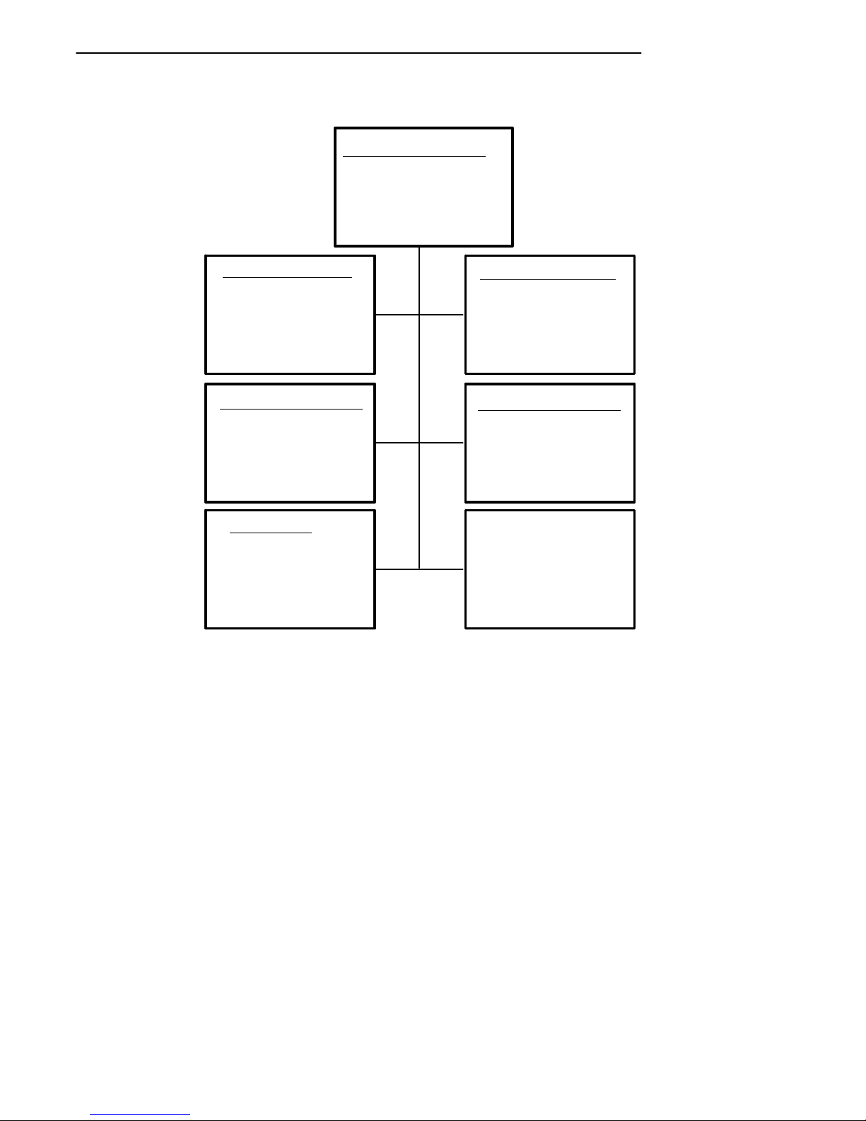
Main Menu
1) Set-up Parms
2) LCD Parms
3) Beeper Setup
4) Tests
5) Version Info
6) Exit Menus
7) More
Set Parameters
1) Radio #
2) Barcode Parms
3) Protocol Opts
4) Display Opts
5) Radio Comm
6) Cold Start
Beeper Setup
1) Key Click
2) Error Tone
3) Beeper Select
Version Info
Firmware name
Version number
Date ddmmyy
(1) (2)
(3) (4)
(5) (7)
LCD Parms
1) LCD Contrast
2) Screen Size
3) Screen Mode
4)
5) Backlight
6) Key Uppercase
7) Scroll Window
Tests
1) Peripherals
2)
3) Memory View
4) Packet Driver
5) Numbers
Main Menu 2
1) Keyboard Opts
2) Save Parms
3) Cloning Opts
4) Session Menu
To return to the Main Menu from the terminal menus program, simply press
(and release) the [ENTER] key several times. You can then select 6) Exit
Menus, to return to the operating system.
The following paragraphs describe options available from the Main Menu.
3-4 RT1700 Radio Data TerminalUser’sGuide
Page 47

SECTION 3 " Menu Screens
Set-Up Parms
The Set-up Parms (parameters) menu is password protected to guard against
unwanted changes or loss of data. Enter the password CR52401 to access
these menus. (This is one of the few times you do not press [ENTER] after
making a selection.)
You can change the following:
" Radio identification number
" Bar code parameters
" Host and emulation mode options
" Display options
" Radio Comm (not user accessible at this time)
Or, you can perform a cold start.
LCD Parms
This menu adjusts the following display (Liquid Crystal Display) parameters:
" Contrast
" Screen size (number of lines displayed and the number of characters
per line)
" Cursor position (Screen Mode)
" Backlight timer
" Uppercase display
" Scrolling window parameters
RT1700 Radio Data TerminalUser’s Guide 3-5
Page 48

SECTION 3 " Menu Screens
Beeper Setup
Beeper Setup lets you adjust the frequency and the length (duration) of the
buzzer. Different buzzer tones can be programmed, and you can select the
buzzer output:
" Key click (The buzzer tone indicating a valid key has been pressed or
a good scan has occurred).
" Error tone (the buzzer tone indicating some error condition has oc-
curred. For example, an illegal or inappropriate key stroke.).
" Internal output (terminal buzzer) or headset output.
Tests
The Tests menu allows you to perform the following tests:
" Peripherals
" Packet driver
" Numbers
Version Info
You can use the UP and DOWN arrow keys in the VersionInfo option menu
to display:
" The type of program in FLASH ROM.
" The release date of the program in FLASH ROM.
" The terminal serial number.
" Various software components.
Exit Menus
The Exit Menus option is used to exit from the terminal menus and return to
the power-up screen.
More
The More option opens a menu called Main Menu 2, which lets you (1) set
a keyboard “type-ahead” option, (2) save parameter settings as the new
terminal default parameters, (3) clone and communicate parameters to other
terminals electronically, and (4) designate session switching parameters.
3-6 RT1700 Radio Data TerminalUser’sGuide
Page 49

SECTION 3 " Menu Screens
Opening the Set-Up Parms Menu
The Set-Up Parms (“parameters”) menu is password protected to prevent
unauthorized persons from changing terminal parameters.
Parameter settings you make apply only to the current session. If more than
one session is available to you, use the Session Menu (#4 in Main Menu 2)
to verify or change the current session before making parameter settings.
57-Key Standard Terminal
To open the Set-Up Parms menu:
" press the [1] key,
" press the [ENTER] key,
" at the prompt, enter the password CR52401.
The Set-Up Parms menu, and the menus you can access from it, are shown
on the following page.
37-Key Terminal Special Instructions
The 37-key keyboard option varies slightly from the standard 57-key terminal. Because of this, the key-entry sequences for the Password, and to initiate a Cold Start are slightly different on the 37-key terminal.
Setup Menu Access
Press the gold-colored menu key and then press the black MENU key to
open the user setup menus. This step remains the same as on the standard
57-key terminal.
Password Procedure
Since there are no alphabet keys on the 37-key keyboard, you must press
F12, F11and then enter 52401 to access password-protected menus.
COLD START Procedure
You must press the F10 key in place of the Y (“yes”) key to initiate the
“COLD START”menu option.
RT1700 Radio Data TerminalUser’s Guide 3-7
Page 50
SECTION 3 " Menu Screens
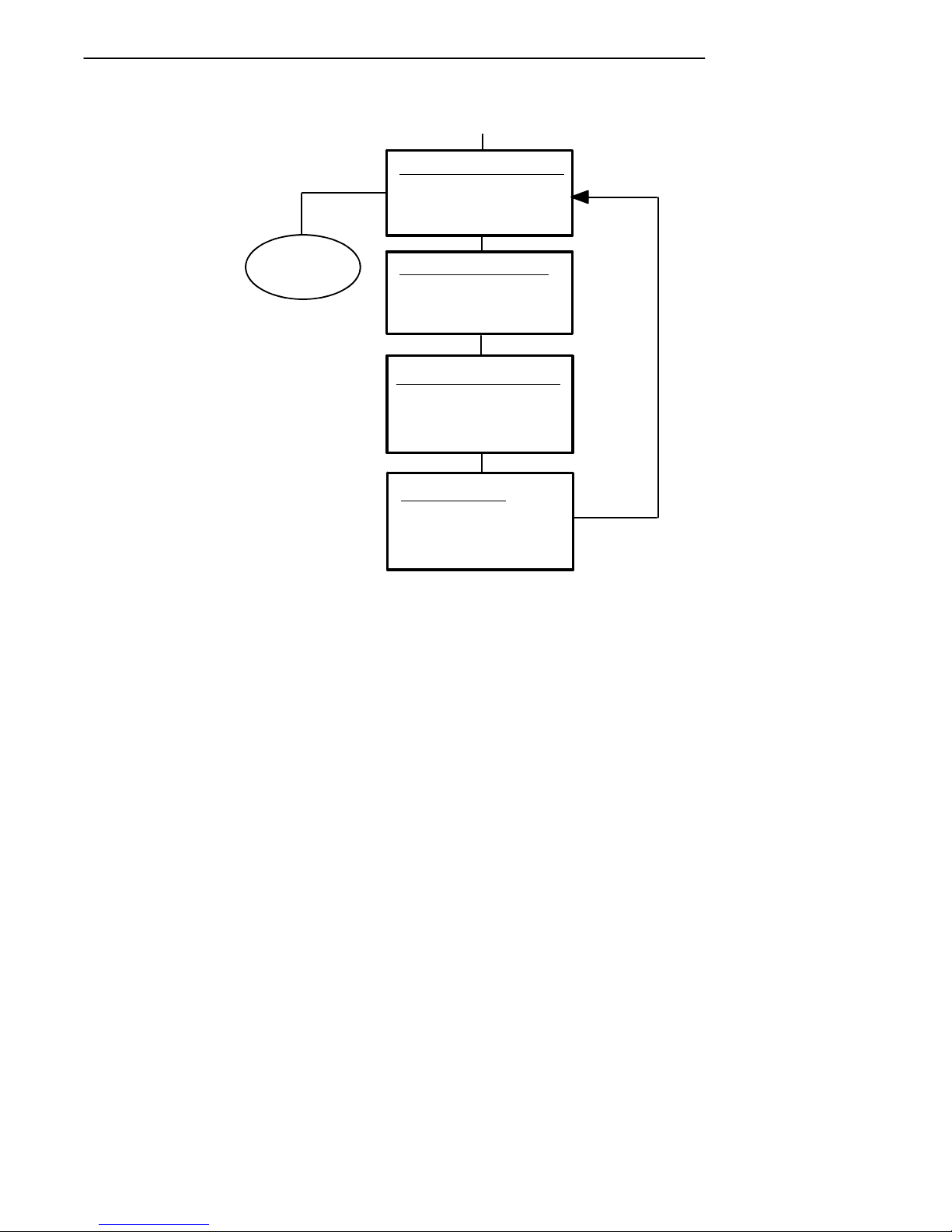
Set-up Parms
1) Radio #
2) Barcode Parms
3) Protocol Opts
4) Display Opts
5) Radio Comm
6) Cold Start
‘ADVANCED SETUP’
ONLY APPLIES TO
SST AND OWL RA-
DIOS
Enter Unit
Number:
Press A for
Advanced Setup
1) Host View Size
2) Data Stream
3) Extended Cmds
4) 5250
5) 3270
6) VT220
7) Native
Radio #
xx
Protocol Opts
Radio Comm
1) Protocol
2) Baud Rate
(1) (2)
(3) (4)
(5) (6)
Scanner Type
1) No Scanner
2) Wand
3) Laser
4) Wand Emulate
5) Auto Detect
Display Opts
1) Backlight
2) Cursor Mode
3) Remote Disp
Cold Start
Enter “Y”
To Cold Start
Terminal:
3-8 RT1700 Radio Data TerminalUser’sGuide
Page 51

SECTION 3 " Menu Screens
Radio #
Use the Radio # menu to set, view, or change the terminal identification
number. This number allows the host computer to identify individual terminals in the radio data network. Each terminal must have a unique number. Do not assign the same number to two terminals in the same network).
To set or change the terminal identification number use the numeric keys on
the terminal keyboard. After entering a number (between 0 and 126), press
the [ENTER] key to return to the Main Menu, or the [A] key to go to the
Advanced Setup menus.
The LAN ID number can be 0--254 depending on the radio you are using.
With the Proxim 2.4 Ghz radio, the range is 0--15. Your terminal will only
be able to communicate with equipment using the same ID number that you
assigned to your LAN.
The second option in the Advanced Setup menu allows you to change the
radio configuration setting. At the present time this is not used and is left
available for custom settings necessary at a particular customer site. An
Intermec System Engineer will work with the customer to make this setting.
RT1700 Radio Data TerminalUser’s Guide 3-9
Page 52

SECTION 3 " Menu Screens
If your terminal has a 902 Mhz radio module, use the up and down arrows
to pick the Direct Sequence (DS) and Channel configuration.
Use the next option if there is more than one host computer on your OWL
network. This allows you to designate up to three host computers the terminal can communicate with. Each host is assigned a separate priority
level (1, 2, or 3). When powered on, the terminal seeks host A. If host A
is not available, the terminal seeks host B; if host B is not available, the
terminal logs on to host C.
When designating additional hosts, you must:
" Tell the terminal the communication protocol of each host
computer (Native, 3270, 5250, or VT220).
" Assign a terminal number to the terminal for each host.
" Tell the terminal the name of each host.
"
NOTE: If the terminal loses the link with the host it is logged onto, you must turn the termi-
nal off (then back on again) to establish a communication link with a differenthost.
The Set Radio # menu, and the Advanced Setup menus, are shown on the
following page:
3-10 RT1700 Radio Data TerminalUser’sGuide
Page 53

SECTION 3 " Menu Screens
"
NOTE: Selections in these menus apply only to the current session. Use the Session Menu
to verify or change the currentsession.
RM60/70
Radios
Set Mode/Channel
Use Cursor UP
and Down Keys
To Adjust
DS xxxK
Channel xx
Enter Unit
Number: xx
Press A for
Advanced Setup
(not currently available)
Radio #
(A)
Advanced Setup
LAN
X
ENTER
Advanced Setup
Radio Config#
ENTER
RM80/90
Radios
B
RM11/31
Syn UHF
Radio
Set Frequency
Use Cursor UP
and Down Keys
To Adjust
1) Freq Agility
2) Single Freq
B
ENTER (continue on next page)
RT1700 Radio Data TerminalUser’s Guide 3-11
Mode
Page 54
SECTION 3 " Menu Screens
ENTER
(continuation)
Advanced Setup
1) Host A
2) Host B
3) Host C
DONE
(when setup is
complete)
ENTER
1) Native
2) 3270
3) 5250
4) VT220
Enter Unit
Number: xxx
(host emulation)
Unit XXX
Enter Host Name:
xxxx
Host A
ENTER
Host A
ENTER
Host A
ENTER
(repeat for
multiple hosts)
3-12 RT1700 Radio Data TerminalUser’sGuide
Page 55

SECTION 3 " Menu Screens
Bar Code Parms
The Bar Code Parms (parameters) menus are where you designate:
" the type of bar code scanner you are using (if any),
" various scan options,
" the bar code symbologies you want enabled (the terminal can only
decode the bar code symbologies you enable),
" and various options for each enabled bar code symbology (e.g., mini-
mum and maximum bar code lengths).
The Scanner Type menu is the first Bar Code Parms menu you see. Choose
the desired option from this menu and press the [ENTER] key. The next
Bar Code Parms menu appears on the display.
Scanner Type
Use the Scanner Type menu to designate the type of bar code scanner you
are using.
Scanner Type
1) No Scanner
2) Wand
3) Laser
4) Wand Emulate
5) Auto Detect
To make a selection, press the numeric key corresponding to the desired
option, then press the [ENTER] key. The display then advances to the
Scan Options menu.
"
NOTE: You can choose option 1, “No Scanner,”and still set the remaining scanner and bar
code options. Then, if you use a scanner at a later time, all parameters will be set
and it will only be necessary to designate the scanner type.
"
NOTE: Enabled options are highlighted on the display. To deselect an enabled option,
press the key that corresponds to the option.
RT1700 Radio Data TerminalUser’s Guide 3-13
Page 56

SECTION 3 " Menu Screens
Scan Options
Use the Scan Options menu to designate how the terminal handles scanned
bar codes. The Scan Options menu is shown below. Descriptions of each
option follow.
Scan Options
1) Redundancy
2) MOD 10 Check
3) Concatenate
4) BC Type Char
5) Stream Scan
6) Scan All Flds
7) More
Redundancy: Requires two identical scans of a bar code before the terminal accepts the scan as valid.
"
NOTE: When using a wand scanner with redundancy enabled, you must physically scan a
bar code two times (or more)to get two identical scans.
Mod 10 Check: A check digit is added at the end of the bar code after a
good read. This is a variation of the modulus 10 formula and is used infrequently.
For additional information on Mod10, refer to the book “NORAND Asynch-
ronous Radio Data Network Native Data Stream Programmers Guide”
part number: 977-047-010.
Concatenate: Each bar code read is added to the end of the previous bar
code read until the current input field is filled.
When this option is OFF, each bar code read is placed at the beginning of
the current input field. After a bar code read is placed in a field, any subsequent reads replace the first read.
BC Type Char: Adds a character associated with the bar code type at the
beginning of the scanned bar code. Appendix B lists the characters and
their associated bar codes.
Stream Scan: If the scanned bar code is too big for the input field, the overflow information appears in the next field. This continues until the entire
bar code is entered.
3-14 RT1700 Radio Data TerminalUser’sGuide
Page 57

SECTION 3 " Menu Screens
When this option is OFF, and the scanned bar code is too big for the input
field, the overflow information is dropped.
Scan All Fields: The scanner is enabled whenever the cursor is in an input
field. When this option is OFF, the host computer must enable the scanner
each time an input field requires scanned data.
1) Scan Timeout
2) Scan Prechar
3) Scan Postchar
More
Scan Timeout: You can adjust the scanning timeout period from 1 to 200
seconds. When using a proximity-detect scanner you can shorten the timeout period to speed up scanning while also reducing the duration of errant
scans. In the case of a long range scanner, you may want to increase the
timeout period to ensure sufficient aiming time.
To enable the Scan Options, press the numeric key(s) corresponding to the
options you want, then press [ENTER]. You can enable morethan one
Scan Option at a time.
After you press the [ENTER] key,the display advances to additional Scan
Options menus.
Scan Prechar and Scan Postchar: Enter a hex value from 00 -- FF for the
character to be sent preceding the scanned data or after the scanned data.
The value of 20h means that pre-- or post characters will not be sent.
Scan Options (1)
This is one of two menus that can be used to enable (or disable) various bar
code symbologies. To enable a bar code, press the numeric key corresponding to the number of the bar code (as shown on the menu), then press the
[ENTER] key.
After enabling a particular bar code you may have to select various options
for the bar code. After selecting the desired options, you are prompted to
RT1700 Radio Data TerminalUser’s Guide 3-15
Page 58

SECTION 3 " Menu Screens
set length requirements (such as minimum and maximum length, fixed
lengths, leading and trailing character options, etc.).
Once the length requirements have been set, the display returns to the same
Scan Options menu. You may then choose to enable another bar code
symbology from that menu, or you can advance to the next Scan Options
menu by pressing the [ENTER] key without making a selection from the
menu.
The Scan Options (1) menu, and the bar code symbologies you can enable
from it, are shown here. Additional information on bar code symbologies
can be found in Appendix B.
3-16 RT1700 Radio Data TerminalUser’sGuide
Page 59

Scan Options (1)
1) UPC
2) EAN
3) Code 39
4) Code 128
5) Codabar
SECTION 3 " Menu Screens
UPC
1) Enabled
2) Add-On 2
3) Add-On 5
4) Sys 1 UPCE
5) Sys 0 UPCE
6) Expand E To A
Code 39
1) Enabled
2) Chk Digit
3) Extended
4) Encoded
5) Auto-Encoded
6) Relax Std
7) Full ASCII
RELAX CODE 39
1) Quiet zone
2) Data decode
3) Element decode
4) START decode
"
NOTE: See the TECHNICAL OVERVIEW manual or PROGRAMMER’S guide for the pro-
(1) (2)
(3) (4)
*
(5)
EAN
1) Enabled
2) Add-On 2
3) Add-On 5
4) Expand 8To13
Code 128
1) Enabled
2) UCC/EAN
Codabar
1) Codabar
2) ABC Codabar
tocol emulation you are using for details about encoded bar codes.
RT1700 Radio Data TerminalUser’s Guide 3-17
Page 60

SECTION 3 " Menu Screens
Scan Options (2)
This menu offers additional bar code selections. After enabling a bar code
symbology, you can set various options for the bar code, then set length
options for the bar code. When all options have been set, the display returns to the Scan Options (2) menu. The Scan Options (2) menu, and the
bar code symbologies you can enable from it, are shown on the following
page.
When you have enabled all needed bar code symbologies, press the [EN-
TER] key (without making a selection). The display returns to the Scan
Options (1) menu. Press the [ENTER] key again (without making a
selection) to return to the Set-Up Parms menu.
3-18 RT1700 Radio Data TerminalUser’sGuide
Page 61

Scan Options (2)
1) Plessey
2) Str 2of5
3) Int 2of5
4) CI 2of5
5) Code 11
6) Code 93
SECTION 3 " Menu Screens
Plessey
1) Enabled
2) MOD10 Chk
3) MOD11 Chk
4) Allow Alpha
Int 2of5
1) Enabled
2) Chk Digit
Code 11
1) Enabled
2) Chk Dig 1
3) Chk Dig 2
(1) (2)
(3) (4)
(5) (6)
Str 2of5
1) Enabled
2) Disabled
CI 2of5
1) Enabled
2) Disabled
Code 93
1) Enabled
2) Disabled
RT1700 Radio Data TerminalUser’s Guide 3-19
Page 62

SECTION 3 " Menu Screens
Lengths Options
The Lengths Options menus determine the maximum and minimum length
for a specific bar code symbology. Setting the length of enabled bar codes
helps the terminal determine if a scanned bar code is valid and improves
terminal response time.
The Length Options must be set for each enabled bar code. Instructions for
setting the length options follow the menus.
xxxxxx
Max Length xxxx
xxxxxx
Max Length xxxx
Min Length xxxx
xxxxxx
Max Length xxxx
Min Length xxxx
Fix Length 1 xxxx
xxxxxx
Max Length xxxx
Min Length xxxx
Fix Length 1 xxxx
Fix Length 2 xxxx
xxxxxx
Drop Leading xxxx
Drop Trailing xxxx
xxxxxx
Drop Leading xxxx
xxxxxx
Max Length xxxx
Min Length xxxx
Fix Length 1 xxxx
Fix Length 2 xxxx
Fix Length 3 xxxx
Fix Length 4 xxxx
xxxxxx
Max Length xxxx
Min Length xxxx
Fix Length 1 xxxx
Fix Length 2 xxxx
Fix Length 3 xxxx
3-20 RT1700 Radio Data TerminalUser’sGuide
Page 63

SECTION 3 " Menu Screens
1. Key in the maximum length (0 -- 2000) for the selected bar code, then
press [ENTER].
2. Key in the minimum length (0 -- 2000) for the bar code, then press
[ENTER].
"
NOTE: The next prompt(s) set fixed bar code lengths (the enabled bar code must be of a
certain length—determined by your entry). Fixed-length entries override the maximum and minimum length entries (if you entered maximum and minimum lengths
for the bar code shown, your entries will be ignored). If you do not want fixed
lengths for the enabled bar code, enter zero (0).
3. Press the fixed length (0--2000) for the defined bar code, then press
[ENTER]. Each time you set a fixed length, (then press the
[ENTER] key) you are prompted to set another fixed length—up to
four. Toset fewer than four fixed lengths, enter zero (0) at the first
prompt after you have set the desired fixed lengths. (For example, if
you only require 2 fixed lengths, enter zero when the Fixed Length 3
prompt appears on the display.)
"
NOTE: Use the next two prompts to drop a particular number of characters from the front
(leading) or rear (trailing) edge of the scanned bar code.
4. Enter the number of characters (0--15) to drop from the beginning of
the scanned bar code, then press [ENTER] .
5. Enter the number of characters (0--15) to drop from the end of the
scanned bar code, then press [ENTER] .
After you have set all of the length options for the enabled bar code the
display returns to one of the Scan Options menus (depending on which
menu you enabled the bar code from).
RT1700 Radio Data TerminalUser’s Guide 3-21
Page 64

SECTION 3 " Menu Screens
Protocol Options
Use this selection to designate the type of terminal emulation supported by
the host computer. You can also designate which additional commands and
command sets are available.
The Protocol Opts menu has seven sub menus to customize your terminal.
The Protocol Opts menu is shown below. Following the menu are descriptions of each option on the menu.
Protocol Opts
1) Host View Sze
2) Data Stream
3) Extended Cmds
4) 5250
5) 3270
6) VT220
7) Native
3-22 RT1700 Radio Data TerminalUser’sGuide
Page 65

SECTION 3 " Menu Screens
Host ViewSize
The Host ViewSize option tells the terminal the format of display information sent from the host. The default setting is 25 characters high by 12 or 16
characters wide (depending on your terminal).
Host View Sze
Width
16
The number of characters shown on each line can be set from 1 to 80. (For
example, if the host display is 60 characters wide, you will want to set the
Host ViewSize option to 60.)
To change the width, enter a number (between 1 -- 80), then press
[ENTER]. The display returns to the Protocol Opts menu.
Data Stream
Use this menu to specify the communication protocol used by the host computer.
Data Stream
1) Native
2) 3270
3) 5250
4) VT220
Enter the number corresponding to the protocol of the host computer, then
press [ENTER]. The display returns to the Protocol Opts menu.
RT1700 Radio Data TerminalUser’s Guide 3-23
Page 66

SECTION 3 " Menu Screens
Extended CMDS
With this option ENABLED, the host computer can change the following
parameters on the terminal:
" RS-232 communications (e.g., printer)
" Bar code options
" Display screen and font size
1. Press [1] to enable the extended command set, or press [2] to disable
the extended command set.
2. Press [ENTER] to return to the Protocol Opts menu.
Extended Cmds
1) Enabled
2) Disabled
3-24 RT1700 Radio Data TerminalUser’sGuide
Page 67

SECTION 3 " Menu Screens
5250 Options
The 5250 Options menu lets you enable the following features if you are
using the 5250 communication protocol:
" Beep On Error
" Auto Tab Scan
5250 Options
1) Beep On Error
2) Auto Tab Scan
3) Telnet
Enabling Beep On Error causes the buzzer to sound, but allows you to continue working (normally,when an error occurs the keyboard locks-up, and
must be reset either from the host or the RESET key on the terminal itself).
The Auto Tab Scan option causes the cursor to automatically tab forward to
the next input field when a good scan is obtained.
To enable either option:
1. Press [1] to enable the Beep On Error option.
Press [2] to enable the Auto Tab Scan option.
2. Press [ENTER] to return to the Protocol Options menu screen.
When you choose the Telnet option here, or in any of the other menus that
follow,the terminal is directed to use the Telnet communication protocol for
network communication.
RT1700 Radio Data TerminalUser’s Guide 3-25
Page 68

SECTION 3 " Menu Screens
3270 Options
The 3270 Options menu lets you enable the following features if you are
using the 3270 communication protocol:
" Keyboard Unlock
" Auto Tab Scn (scan)
" Auto Entr (enter) Scn
" Emulate 3210
1) Keybrd Unlock
2) Auto Tab Scan
3) Auto Entr Scn
4) Emulate 3210
5) Telnet
3270
Enabling Keyboard Unlock unlocks the keyboard after the [PA1], [PA2],
or [CLEAR] keys are pressed. (Normally the keyboard remains
locked—until unlocked or reset by the host—after any of these keys are
pressed.) When using Token Ring as your host, the tab key will also unlock
the keyboard.
Enabling Auto Tab Scan causes the cursor to tab forward to the next input
field whenever a good scan is obtained.
Enabling Auto Entr Scan actuates the [ENTER] function whenever a good
scan is obtained.
"
NOTE: Auto Tab Scan and Auto Entr Scan cannot be enabled at the same time.
3-26 RT1700 Radio Data TerminalUser’sGuide
Page 69

SECTION 3 " Menu Screens
3210 Emulation
The 3210 emulation option causes the RT1700 terminal to perform the
same functions as the RT3210 terminal. For full 3210 compatibility: you
must disable buffering the keyboard, set cursor to lazy mode, and LCD
Parms to Key Uppercase.
After enabling the desired 3270 options, press the [ENTER] key to return
to the Protocol Opts menu.
VT220
The VT220 menu lets you enable the following features if you are using the
VT220 communication protocol:
" DEL to BS (delete to backspace)
" CR to CRLF (carriage return to carriage return line feed)
" Auto Entr (enter) Scn
" Auto Tab Scan
" Local Echo
" Answerback
" More
VT220
1) DEL to BS
2) CR to CRLF
3) Auto Entr Scan
4) Auto Tab Scan
5) Local Echo
6) Answerback
7) More
The DEL to BS option, when enabled, causes the [CLEAR] key to delete
the character to the left of the cursor position, and moves the cursor back
one space. When this option is not enabled, the [CLEAR] key deletes the
character at the cursor position.
The CR to CRLF option, when enabled, causes the [ENTER] key to perform a carriage return and line feed. When this option is not enabled, the
[ENTER] key performs a carriage return only.
RT1700 Radio Data TerminalUser’s Guide 3-27
Page 70

SECTION 3 " Menu Screens
Enabling Auto Entr Scn actuates the [ENTER] function whenever a good
scan is obtained.
The Auto Tab Scan option causes the terminal to automatically tab to the
next input field when a good scan is obtained.
"
NOTE: The Auto Entr Scan and Auto Tab Scan options cannot be enabled at the same time.
Enabling the Local Echo option allows characters to be displayed from terminal memory and not from host memory.
The Answerback option allows the user to input up to a 30 character string,
which is then sent back to the host in response to an enq
(hex 05).
The More option calls up the following screen(s):
First “More” Second “More”
VT220
1) Screen Lock
2) DiscreteBells
3) UserKey Locked
4) RS232 Setup
5) VT220 Mode
6) Lock Mode
7) More
VT220
1) Telnet
The Screen Lock option allows the user to set up and lock in a specified
screen size. Characters falling outside this screen size will be ignored by
the terminal.
If the DiscreteBells option is enabled, the host terminal will send a tone for
each input character. If disabled, the terminal will sound normally with
each input character, unless it is already beeping. In this case, further tones
will be ignored.
RS232 Setup produces Baud Rate, Parity,Stop Bits, Data Bits, and flow
setup menus.
After enabling the desired VT220 options, press the [ENTER] key to return to the Protocol Opts menu.
3-28 RT1700 Radio Data TerminalUser’sGuide
Page 71

SECTION 3 " Menu Screens
Native (F1 is Func-0)
This option is enabled by default to preserve backward compatibility. When
enabled, pressing <F1> is equivalent to pressing Black 0, while pressing
<F2> is equivalent to Black-1, etc. When disabled, <F1> is equivalent to
Black-1, and <F2> is equivalent to Black-2, etc.
Native
1) F1 is Func-0
Display Options
Display Opts allows you to:
" Set the length of time the backlight stays on when the terminal is
inactive.
" Choose how the cursor appears on the display.
" Access an additional menu that allows you to enable the remote dis-
play or set the screen size.
Display Opts
1) Backlight
2) Cursor Mode
3) Remote Disp
RT1700 Radio Data TerminalUser’s Guide 3-29
Page 72

SECTION 3 " Menu Screens
Backlight
The Backlight option lets you set the length of time the backlight stays on
after the last entry.
To adjust the backlight timer, press the [Y] (up) or [B] (down) arrow key.
The timer can be set from 1 to 25 seconds, or OFF (which disables the
backlight). To set the backlight OFF, back the timer below 1. Press the
[ENTER] key when you have set the timer to the desired length of time.
The display returns to the Display Opts menu.
Backlight Timer
Use Cursor Up
and Down Keys
To Adjust
xxx
"
NOTE: The backlight uses considerable battery power. To ensuremaximum use from the
battery pack between charges, always set the backlight timer to the shortest practical time.
3-30 RT1700 Radio Data TerminalUser’sGuide
Page 73

SECTION 3 " Menu Screens
Cursor Mode
Cursor Mode allows you to specify the cursor style you prefer.
Cursor Mode
1) Underline Blink
2) Block Blink
3) Underline
4) Block
> <
" The Underline mode shows the cursor location with a solid underline
( _ ) character.
" Cursor location in the Block mode is indicated by a reverse video
(highlighted) block (J) character.
" Blink modes will blink the respective cursor.
After making your selection, press the [ENTER] key. The display returns
to the Display Opts menu.
Remote Display
This menu allows communication to a remote display. You can specify the
screen size, the remote baud rate (9600, 19,200, 38,400), and the terminal
type (VT100, VT220, ANSI).
Remote Display
1) Enabled
2) Screen Size
3) Remote Baud
4) Remote type
RT1700 Radio Data TerminalUser’s Guide 3-31
Page 74

SECTION 3 " Menu Screens
Radio Comm
These menus allow you to specify the communication protocol and speed
of the terminal when equipped with older UHF or SST radio modules.
UHF ONLY
Protocol
1) RTC
2) Adaptive Poll
3) RTC Diag Mode
OR
Protocol
1) SST
2) SST - Diag Mode
SST ONLY
Radio Comm
1) Protocol
2) Baud Rate
(1) (2)
(1)
Baud Rate
1) 4800
2)
3) 9600
#2 OPTION ‘BAUD
RATE’ APPLIES TO
UHF ONLY
UHF ONLY
"
NOTE: Diagnostic modes disable data compression and are reserved for engineering tests.
3-32 RT1700 Radio Data TerminalUser’sGuide
Page 75

SECTION 3 " Menu Screens
Cold Start
The Cold Start option performs a terminal cold start. A cold start resets all
terminal parameters to their default values.
Cold Start
Enter “Y”
To Cold Start
Terminal:
Press the [Y] key to cold start the terminal, or press any other key to return
to the Set-Up Parms menu.
RT1700 Radio Data TerminalUser’s Guide 3-33
Page 76

SECTION 3 " Menu Screens
LCD Parms (Parameters)
The LCD Parms menu allows you to adjust the following features of the
liquid crystal display:
" The contrast of the display.
" The screen size (number of lines displayed, and the number of char-
acters on each line).
" The screen mode (how the cursor positions itself on the display).
" The intensity (brightness) of the backlight.
" Making all alphabetic character keystrokes display as uppercase char-
acters.
" Scrolling window parameters.
LCD Parms
1) LCD Contrast
2) Screen Size
3) Screen Mode
4)
5) Backlight
6) Key Uppercase
7) Scroll Window
3-34 RT1700 Radio Data TerminalUser’sGuide
Page 77

SECTION 3 " Menu Screens
LCD Contrast
Use LCD Contrast to adjust the contrast of the display to a level that is most
readable for the user. The terminal uses this setting as a baseline, automatically readjusting contrast as necessary,based upon temperature changes.
LCD Contrast
Use Cursor Up
and Down Keys
To Adjust
xxx
To adjust the contrast:
" Press the [Y] or [B] arrow key to adjust.
" When the display is most readable, press the [ENTER] key.
RT1700 Radio Data TerminalUser’s Guide 3-35
Page 78

SECTION 3 " Menu Screens
Screen Size
Screen Size lets you select the number of lines, and the number of characters in each line, that can be viewed on the display. Choices include:
" 4 lines, with 12, 17, 22, or 26 characters per line
" 6 lines, with 12, 17, 22, or 26 characters per line
" 8 lines, with 12, 17, 22, or 26 characters per line
" 10 lines, with 12, 17, 22, or 26 characters per line
" 12 lines, with 12, 17, 22, or 26 characters per line
" 16 lines, with 12, 17, 22, 26, or 31 characters per line
" 21 lines, with 12, 17, 22, or 26 characters per line
Only one option can be selected at a time.
Screen Size
12 17 22 26 31
4 Off Off Off off
6 Off Off Off off
8 Off Off On off
10 Off Off Off off
12 Off Off Off off
16 Off Off Off off off
21 off off off off
To change the screen size:
1. Press the arrow keys. Each key press moves the word On one position in the direction pressed. The word On indicates the current setting (the setting above is 8 lines with 22 characters per line—the
word On is in the row 8, column 22.
2. When you have set the desired screen size, press the [ENTER] key.
3-36 RT1700 Radio Data TerminalUser’sGuide
Page 79

SECTION 3 " Menu Screens
Screen Mode
Use Screen Mode to select cursor position and movement as you scroll
through data in the display buffer. This buffer stores data in a standard CRT
format (as sent from the host computer). Since your terminal screen is
smaller than a CRT,these Screen Mode options allow you to optimize your
view of information (data) on the terminal display.
In order to see all of the data, use the arrow keys to scroll (or “move”) the
data across the screen.
Screen Mode
1) Center Cursor
2) Corner Mode
3) Page Mode
4) Lazy Mode
Center Cursor is the default mode. The cursor begins near the center of
the display and attempts to remain there as you scroll through the data.
Upon reaching an outside boundary of the full CRT screen, the display
stops advancing while the cursor moves beyond the center of the screen.
When the cursor reaches the boundary of the CRT screen, an error tone
sounds (the terminal “beeps”). The cursor does not wrap to the next line in
the display. This option is recommended when your application program
sends the full CRT display to the terminal.
The Corner Mode option starts the display at the upper-left corner of the
full CRT screen and keeps the cursor in the lower-right corner of the display. As you scroll, the cursor remains there as data advances in the
scrolled direction (up, down, right, or left)—until an outside boundary of
the full CRT screen is reached. Then, the display stops moving and the
cursor moves in the scrolled direction (the cursor no longer remains in the
corner of the display). When the cursor reaches the CRT screen boundary
it stops moving (the cursor does not wrap to the next line in the display).
An error tone sounds if you try to move the cursor beyond the boundary.
This option is recommended when your application uses only the upper-left
corner of the full CRT screen.
RT1700 Radio Data TerminalUser’s Guide 3-37
Page 80

SECTION 3 " Menu Screens
The Page Mode option divides the full CRTscreen into predefined “pages,”
and starts the terminal display on page 1. The cursor first appears in the
upper-right corner of the display. As you scroll, only the cursor moves (the
data on the screen does not appear to move). When you scroll off the edge
of the displayed page, the display snaps to the next (or previous) page.
Upon reaching the boundary of the CRTscreen, the cursor stops moving
and an error tone sounds each time you attempt to move beyond the boundary.
"
NOTE: Some “pages” in Page Mode overlap each other (the same information is shown on
both pages). This overlap occurs because the 24 line by 80 column CRT screen can
not be divided equally.
Lazy Mode starts the cursor in the upper left corner of the terminal display.
The cursor moves across the display in the scrolled direction. When the
cursor goes beyond the edge of the display,the data begins to move in the
scrolled direction and the cursor remains at the edge of the display. When
you reach an outside boundary of the full CRTdisplay, an error tone sounds
each time you try to move beyond the boundary.
3-38 RT1700 Radio Data TerminalUser’sGuide
Page 81

SECTION 3 " Menu Screens
Backlight
The Backlight menu allows you to adjust the intensity (brightness) of the
display backlight. The intensity can be set from 0 (off) to 15 (fully on).
BLight Intensity
Use Cursor Up
and Down Keys
To Adjust
xxx
Keep in mind that the backlight uses considerable battery power. You will
conserve battery power by keeping the intensity and the duration of the
backlight as low as posssible. To adjust the backlight intensity:
1. Press the [Y] or [B] keys to adjust the intensity of the backlight.
Each press of the [Y] key increases the intensity,and each press of
the [B] key decreases the intensity.
2. When the backlight is bright enough, press the [ENTER ] key. The
display returns to the LCD Display menu.
Key Uppercase
The Key Uppercase option, when enabled, places all uppercase alphabet
characters on the display.
RT1700 Radio Data TerminalUser’s Guide 3-39
Page 82

SECTION 3 " Menu Screens
Scroll Window
Menu items are: (1) Tab Size, (2) ScreenSize, (3) Define Width, and (4) De-
fine Height. Choices 1 and 2 allow you to define the size (tab size, or screen
size) of cursor movement: how far it moves with each press of the arrow
key. Choices 3 and 4 allow you to customize the screen size.
This menu allows you to define the size of cursor movement: how far it
moves with each press of the arrow key.
Option 1 causes the cursor to move by 8 in the direction selected.
Option 2 causes the cursor to move over by the virtual screen size selected.
Scroll Window
1. Tab Size
2. Screen Size
3. Define Width
4. Define Height
Options 3 and 4 are used to manually define the x-axis and y-axis position
movement of the cursor.
Beeper Setup
The Beeper Setup menus allow you to adjust the the beeper tones for key
clicks (presses) and error conditions. “Beeper Select” allows you to direct
the audio output to the internal buzzer or to a headset.
3-40 RT1700 Radio Data TerminalUser’sGuide
Beeper Setup
1) Key Click
2) Error Tone
3) Beeper Select
Page 83
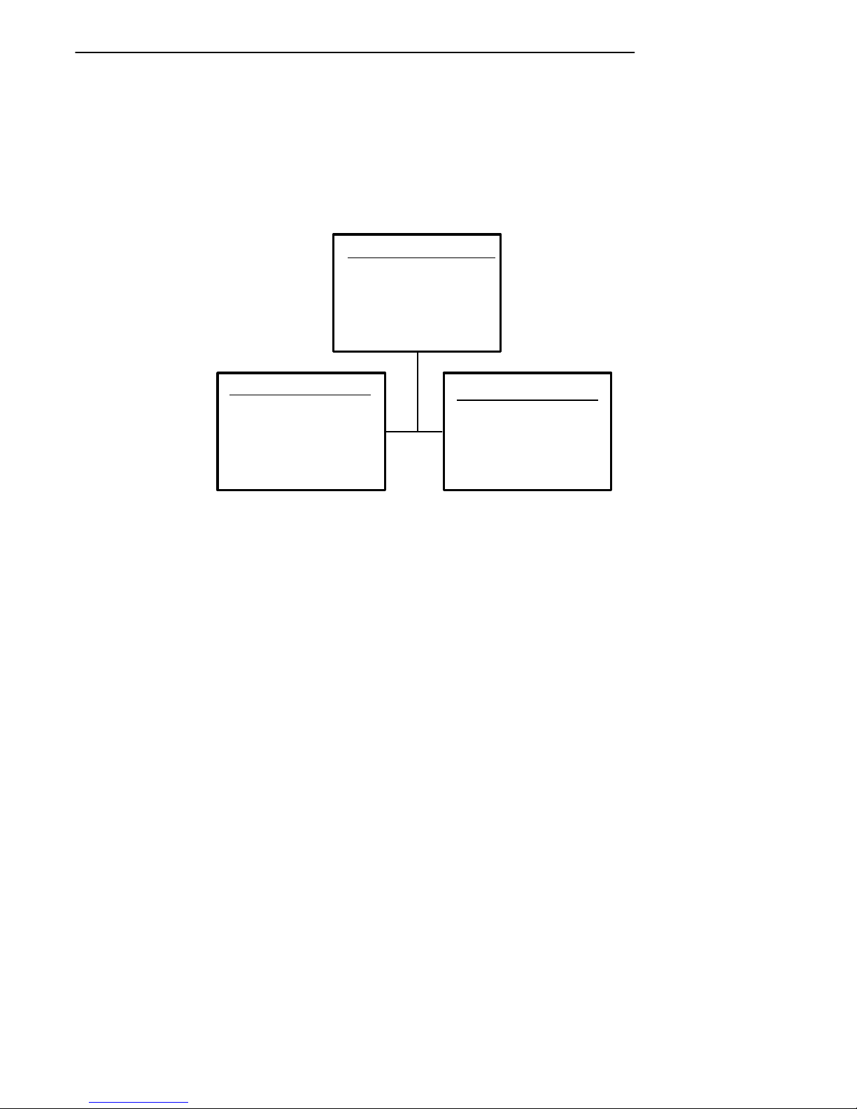
SECTION 3 " Menu Screens
Key Click
Use Key Click to adjust the frequency and length (duration) of the sound
made when you press a key.
The frequency of the tone is adjustable in steps from 0 to 32. The length is
adjustable in steps from 0 to 10. The Key Click menus are shown below.
Key Click
1)
2) Length
3) Frequency
Length
Use Cursor Up
and Down Keys
To Adjust
Key Click> xx
(2) (3)
Frequency
Use Cursor Up
and Down Keys
To Adjust
Key Click> xx
To adjust the key click tone:
1. Press key [2] or key [3].
2. Press the [Y] or [B] keys to make the desired adjustment. Each
key press is accompanied by a tone at the new frequency or length.
3. Press ENTER to confirm your selection and return to the Beeper
Setup Menu.
RT1700 Radio Data TerminalUser’s Guide 3-41
Page 84

SECTION 3 " Menu Screens
Error Tone
The Error Tone option lets you to adjust the length and frequency of the
tone made when an error occurs (for example, pressing an invalid key). The
Error Tone adjustments and the procedures for making them are identical to
the Key Click adjustments.
Beeper Select
This menu allows you to direct the audio output (e.g., buzzer error tones,
key clicks, good scan tone, etc.) to either the internal buzzer or to an external headset. The headset plugs into the mini-DIN connector on the bottom
of the terminal, and has its own in-line volume control. Press 1 to direct
the audio to the internal buzzer, or press 2 to direct sound to the headset.
Beeper Select
1) Beeper Internal
2) Beep Head Set
3-42 RT1700 Radio Data TerminalUser’sGuide
Page 85

Tests
SECTION 3 " Menu Screens
The Tests menus allow you to test peripherals, the display,RF communications, and memory.
Tests
1) Peripherals
2)
3) Memory View
4) Packet Driver
5) Numbers
6) Timed Numbers
Peripherals
The Peripherals menu allows you to test various terminal peripheral devices.
There are currently five different tests:
" Radio Test (password-protected).
" RS-232, which tests the communication port on the terminal.
" Display,which tests the operation of the terminal display.
" Keyboard, which tests the operation of the terminal keyboard.
" Scanner, which tests the operation of a bar code scanner attached to
the terminal.
The peripherals menu is shown below. Detailed descriptions of each peripheral test follow.
Peripherals
1) Radio Test
2) RS232 Test
3) Display Test
4) Keyboard Test
5) Scanner Test
RT1700 Radio Data TerminalUser’s Guide 3-43
Page 86

SECTION 3 " Menu Screens
Radio Test
The Radio Test is used for calibration purposes and is password-protected
by a unique seven-digit password before the menu will display. Technicians
and engineers use these tests to determine the performance of the radio
transceiver at different communication speeds and modes of operation.
RS232 Test
The RS232 Test checks the data communication port on the bottom of the
terminal (the mini-DIN, or round connector).
This test requires a special loop-back connector that links the following
input and output pins on the data connector:
" The TX output to the to RX input.
" The DTR output to the DSR input.
" The CTS output to the RTSinput.
3-44 RT1700 Radio Data TerminalUser’sGuide
Page 87
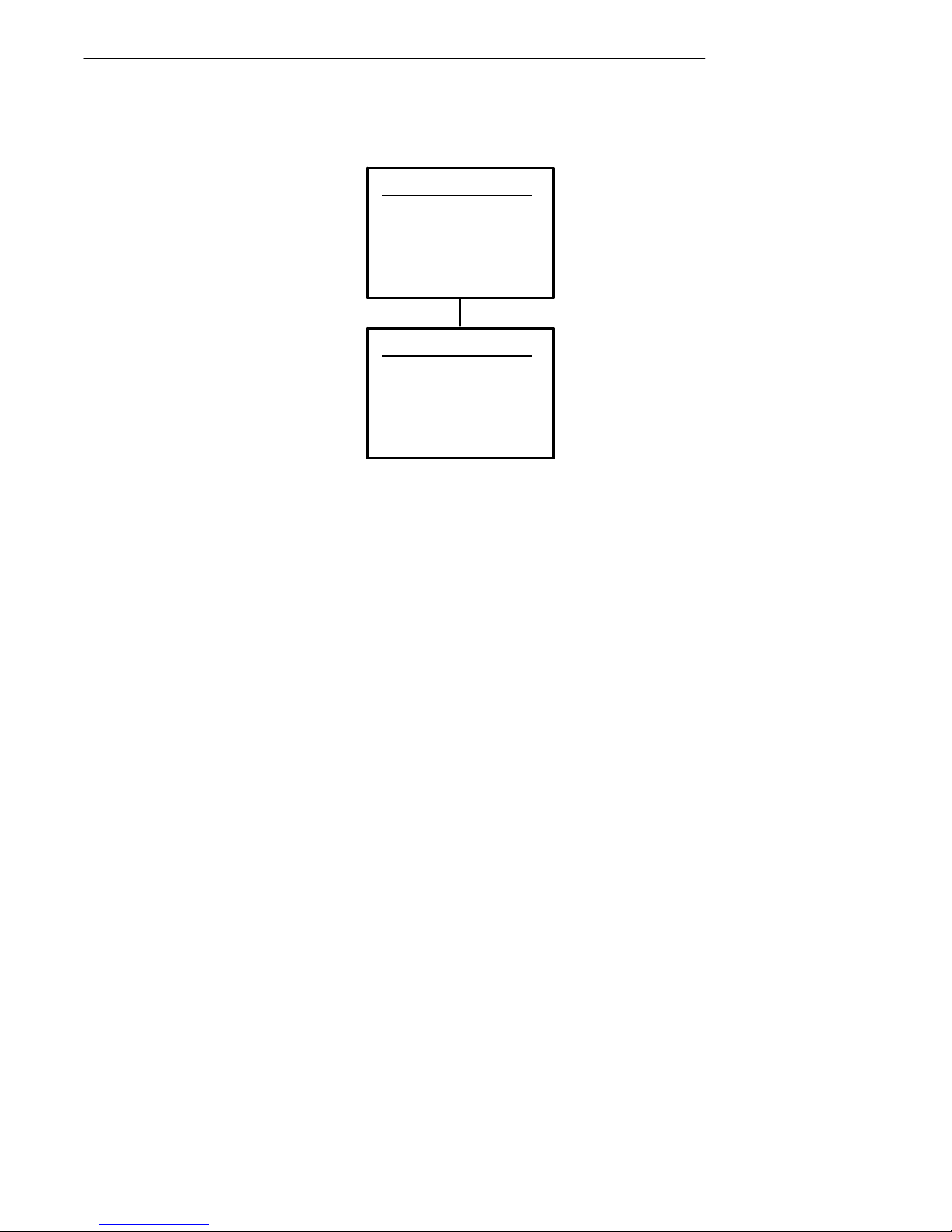
The RS232 Test menu is shown below.
RS232 Test
Attach RS232
Loopback
Connector
Press Enter
RS232 Test
Results:
RTS-CTS: xxxx
TX-RX: xxxx
Any Key To Stop
SECTION 3 " Menu Screens
To run the test:
1. Select the RS232 Test from the Peripherals menu.
2. Attach the loop-back connector to the round connector on the bottom
of the terminal, then press [ENTER]. The display changes to the
second RS232 Test menu (shown above)
The condition of each line-pair displays as passing or failing the test. If any
test fails, the terminal should be returned for service.
RT1700 Radio Data TerminalUser’s Guide 3-45
Page 88
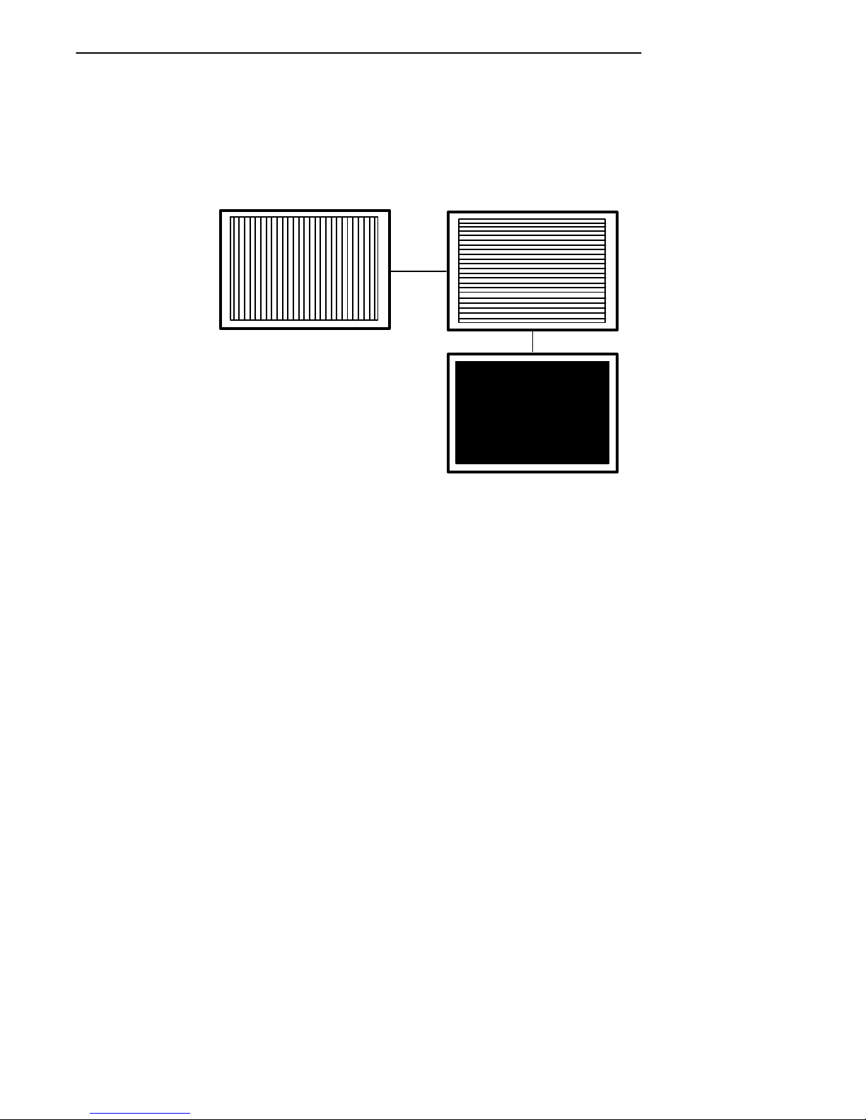
SECTION 3 " Menu Screens
Display Test
The Display Test activates each element in the LCD display. If a line appears broken, or there are gaps in the display,the LCD panel needs to be
repaired or replaced. The Display Test screens, are shown below.
To perform the Display Test:
1. From the Display Test Menu, press [ENTER] to start the test. The
display screen is painted with a series of vertical lines.
2. If all lines appear clear and complete (no broken segments), press
[ENTER]. The display screen is painted with a series of horizontal
lines.
3. If all lines appear clear and complete (no broken segments), press
[ENTER]. The display screen is painted black.
4. If the screen appears to be uniformly black, press [ENTER]. The
display returns to the Peripherals menu.
3-46 RT1700 Radio Data TerminalUser’sGuide
Page 89
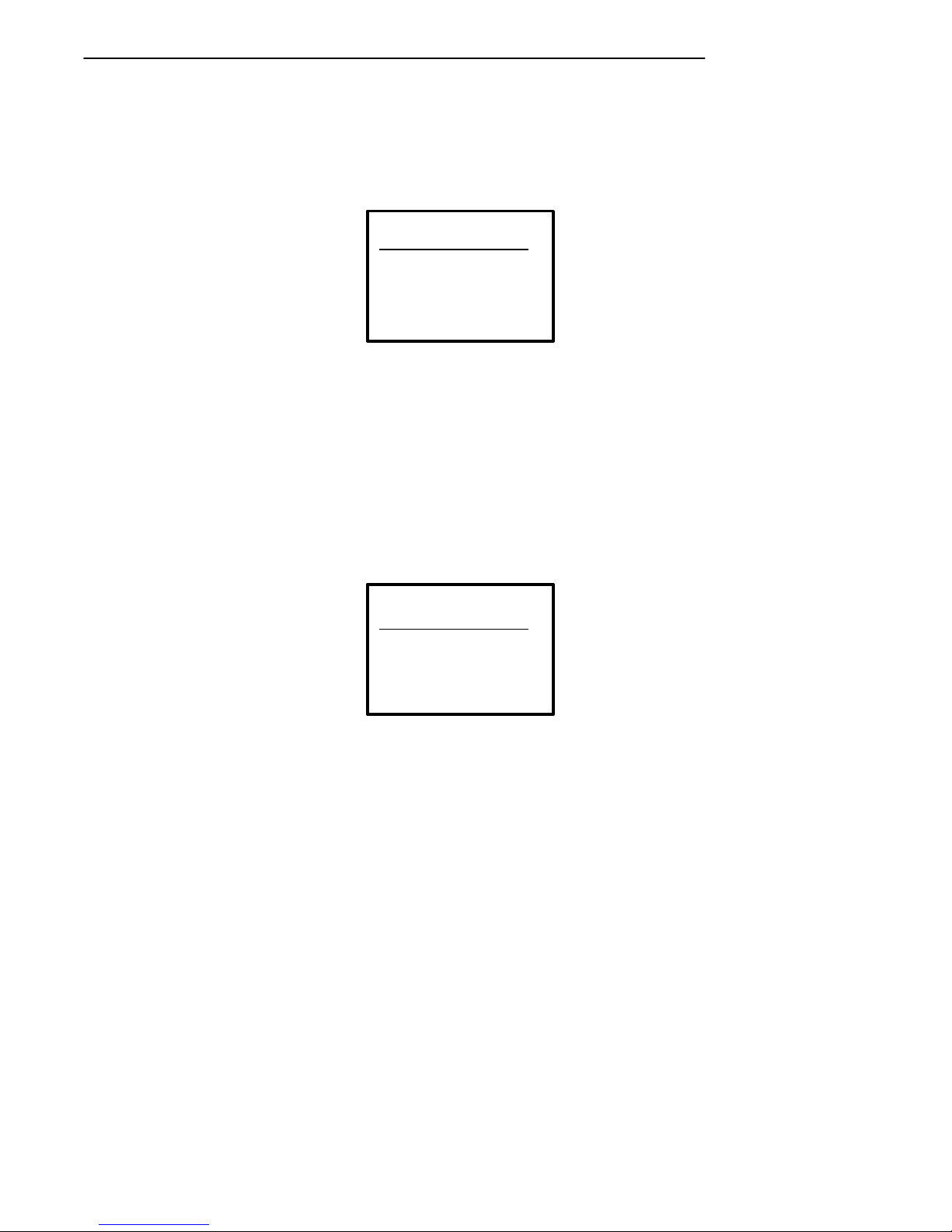
SECTION 3 " Menu Screens
Keyboard Test
The Keyboard Test lets you test each key on the terminal keyboard. The
Keyboard Test menu is shown below:
Keyboard Test
Press a key
ENTER To Exit
Key =
’A’
To perform the test, press each key on the keyboard (except the [ENTER]
key). A character representing the key pressed should appear on the display.
Scanner Test
The Scanner Test allows you to test the operation of an attached bar code
scanned. From the Scanner Test menu, scan an enabled bar code. The bar
code and the bar code length appears on the display. Press any key to exit.
The Scanner Test menu is shown below.
Scanner Test
Scan Code>
Length>
RT1700 Radio Data TerminalUser’s Guide 3-47
Page 90

SECTION 3 " Menu Screens
Memory View
This menu is reserved for engineering test and evaluation.
Packet Driver Test
The Packet Driver tests allow you to test the accuracy of data transmissions
to and from the terminal.
Memory View
F1 - Exit
F2 - Heap
F3 - Far Heap
Address: XXXXXX
Packet Driver
1) Link Test
2) Link Watch
3) Packet Stats
4) Histogram
5) Clear Stats
"
NOTE: Link Test and Link Watch apply to UHF only,and are black when using SST radio.
3-48 RT1700 Radio Data TerminalUser’sGuide
Page 91
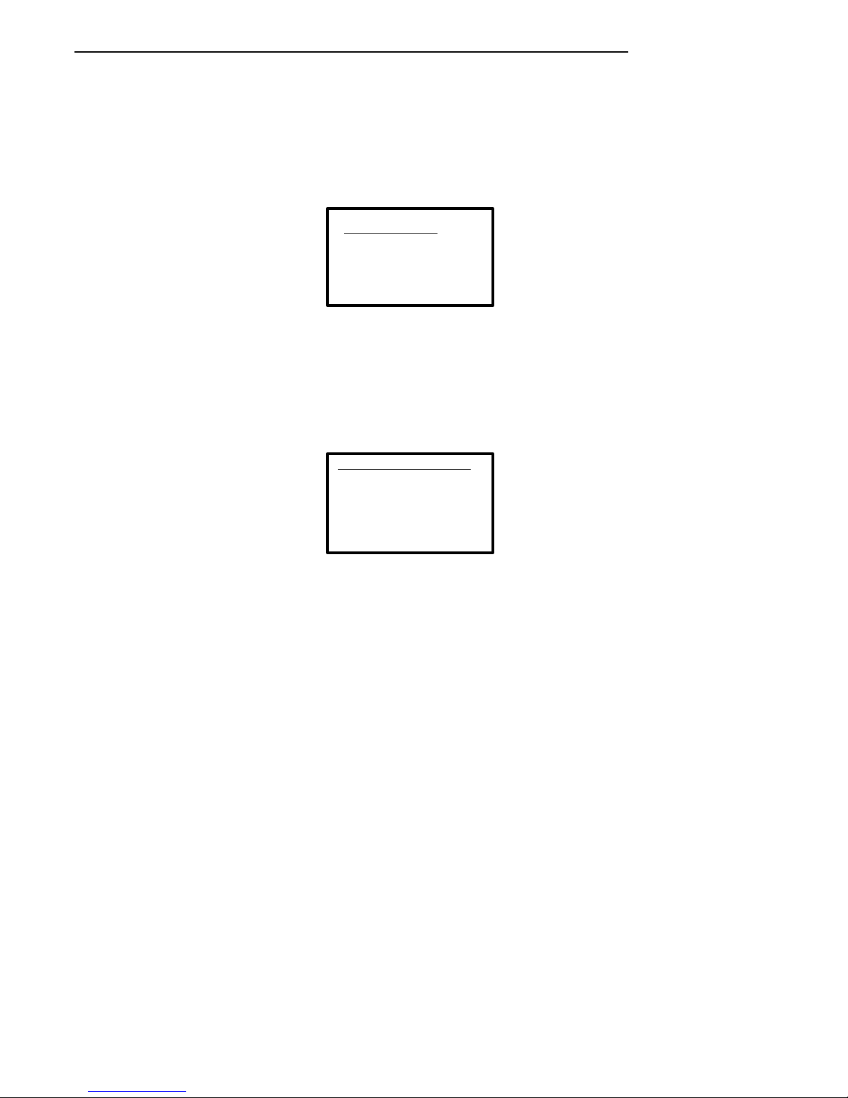
SECTION 3 " Menu Screens
Link Test (UHF only)
The Link Test allows you to display data sent to the terminal, and respond to
test signals from the host computer. Press [ENTER] to end the test and
return to the Packet Driver menu.
Link Test
Respond To Tests
Enter to Exit
Link Watch (UHF only)
Link Watch allows you to view all data transmissions occurring in the terminal (between the terminal and the controller). Press [ENTER] to end the
test and return to the Packet Driver menu.
Link Watch
View All Traffic
Enter to Exit
RT1700 Radio Data TerminalUser’s Guide 3-49
Page 92

SECTION 3 " Menu Screens
Packet Stats
The Packet Stats (statistics) test shows the number of packets sent and
received, number of errors, and number of packets dropped.
Receive
Statistics
Pkt xxx
Chr xxx
Err xxx
Lost xxx
Transmit
Statistics
Pkt xxx
Chr xxx
Err xxx
Transaction
Statistics
Qty xxx
Sec xxx
Qty/Min xxx
Ops xxx
RTC Statistics
3-50 RT1700 Radio Data TerminalUser’sGuide
* SEE TEXT
‘HISTOGRAM
OPTIONS’
Page 93

SECTION 3 " Menu Screens
Histogram Opts
A technician or systems engineer may ask you to access this menu if your
terminal has problems. From this menu you can provide that individual
with vital information about your terminal.
The actual menus are not shown in this manual, however some of the general terminology is shown below. Several of the menu options, such as
“Clear.. ., ” are password-protected and will only be accessible if the technician or engineer provides you with the correct password.
Terminology you might see:
" avg tx time
" avg trans time
" ptt (push-to-talk) count
" addrs on list
" poll no data
" send retries
" rcv retries
" reset count
" interval time
" time bucket #
If you are asked to access the Stats Opts menus, the technician or engineer
will walk you through it.
Histogram Opts
1) Start
2) Stop
3) View
RT1700 Radio Data TerminalUser’s Guide 3-51
Page 94

SECTION 3 " Menu Screens
Numbers
The Numbers test checks the operation of the terminal microprocessor.
During the test, the terminal display is filled with hex numbers that march
across the screen horizontally and scroll vertically. Character movement
indicates the processor is still running.
This test is helpful in detecting lockups during severe operating conditions.
The Numbers test display is not shown here.
Version Info (Information)
Version Info (Information) menu shows:
" The version of the program loaded in the firmware.
" The release date of the firmware program.
" The terminal identification number.
Use the Y(Up) or B(Down) arrows to view the version number of the
EPROM program, and the H8 processor program The Version Info menu is
shown below.
3-52 RT1700 Radio Data TerminalUser’sGuide
Version Info
Firmware name
Version x.x
Date ddmmyy
Page 95

Exit Menus
More
SECTION 3 " Menu Screens
The Exit Menus option (#6) gets you out of the terminal menus and returns
the terminal to the power-up screen.
The More selection opens Main Menu 2, which is shown below.
Main Menu 2
1) Keyboard Opts
2) Save Parms
3) Cloning Opts
4) Session Menu
Keyboard Opts (Options)
Use the Keyboard Opts menu to choose the Type-Ahead option. This lets
you key in information when the terminal cannot immediately send data to
the host computer.
Keyboard Opts
1) Type-Ahead
RT1700 Radio Data TerminalUser’s Guide 3-53
Page 96
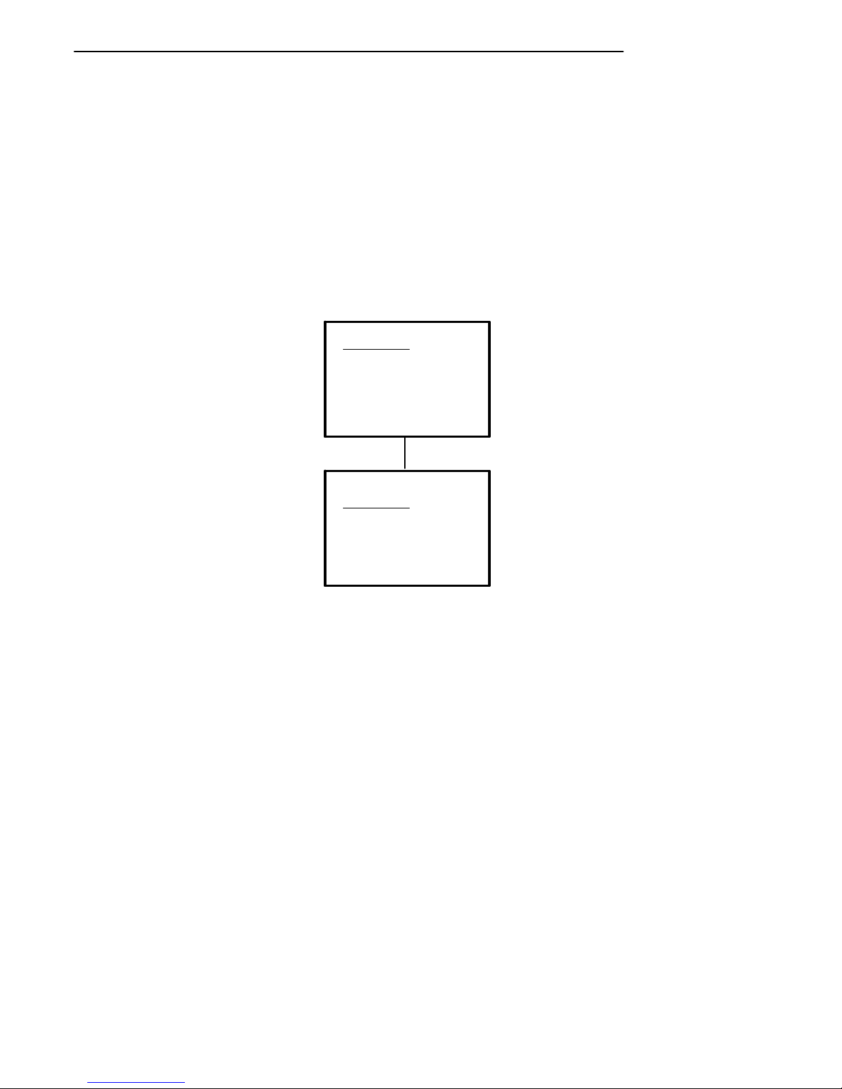
SECTION 3 " Menu Screens
Save Parms
Save Parms retains the parameters you programmed into the terminal.
When you save parameters, they become the default settings for the terminal. When you select Save Parms, you will be prompted to enter a sevendigit password (CR52401), as shown in the following. Once the password
is correctly entered, the terminal automatically begins saving (writing to
FLASH ROM) the parameters.
"
NOTE: Use the Save Parms option sparingly. When you save parameters using this option,
the changes are written to FLASH ROM and are not erased. Each time this option
is used, it occupies additional FLASH ROM memory space.
Save Parms
Enter
Password
> . . . . . . .
3-54 RT1700 Radio Data TerminalUser’sGuide
Save Parms
Working
Please Wait
........
Page 97

SECTION 3 " Menu Screens
Cloning Opts
This function allows you to “clone” (copy) either an application program or
parameter settings from one terminal (the “source” terminal) to another (the
“target” terminal). This requires a cloning cable and both terminals must be
correctly set up for cloning.
To clone an application program from one terminal to another:
1. Connect the terminals using the cloning cable.
2. Turnthe source terminal ON, open the Cloning Opts menu, and select #1, “Clone Prgms.”
3. Depress and hold the I key on the target(receiving) terminal, then
switch it ON; the program from the source terminal will be downloaded into the target terminal.
To clone parameters from one terminal to another:
1. Make sure the desired parameters are already set in the source terminal.
2. Connect the terminals via the cloning cable.
3. Withboth terminals ON, access the Cloning Opts menu.
4. On the sourceterminal, select menu item #2, “Clone Parms.”
5. On the targetterminal, select menu item #3, “Receive Parms.”
Cloning Opts
1) Clone Prgms
2) Clone Parms
3) Receive Parms
RT1700 Radio Data TerminalUser’s Guide 3-55
Page 98
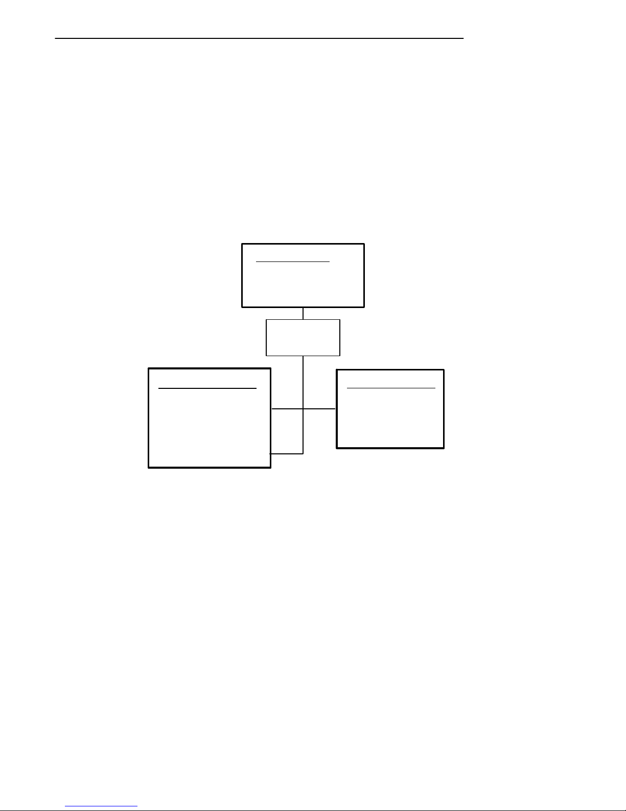
SECTION 3 " Menu Screens
Session Menu
The Session Menu allows you to define different host communication sessions and to designate a “hot key” that allows switching quickly between the
different session.
Use the Switch option to change the current session. The current (or intended) session must be identified (or designated) before setting Parameters.
When you select Set Hot Key,the current hot key is displayed. Use the cursor up and down keys to view the available choices. When the desired key
name is highlighted, press [ENTER] to make your selection. The Set Hot
Key option is only available for terminals that support session switching.
Session Menu
1) Switch
2) Set Hot Key
3) Copy Setup
Select Session
Use Cursor Up
and Down Keys
To Adjust
Session: X
Host: XXXX
<Datastream> XXX
“COPY SETUP” COPIES
PARAMETERS OF BACKGROUND SESSION TO THE
CURRENT SESSION.
3-56 RT1700 Radio Data TerminalUser’sGuide
“Copy Setup”
is password
protected
(1)
(3)
(2)
(2)
Set Hot key
Use Cursor Up
and Down Keys
To Adjust
< xx >
Page 99

Section 4
Maintenance and
Troubleshooting
" " " " " " " " " " " " " " " " " " " " " " " " " " " "
Introduction
This section contains maintenance and troubleshooting procedures for the
RT1700 Radio Data Terminal. Maintenance procedures include instructions on cleaning the terminal and replacing the hand strap. Troubleshooting procedures consist of problems that may be encountered when using a
radio data terminal, and corrective measures you can take to isolate the
problem or to restore normal operation.
Terminal Maintenance
These terminals are designed to withstand normal use in your environment.
However, the terminal does require occasional maintenance to ensure continued trouble-free operation.
The following paragraphs include maintenance procedures that help keep
your terminal in good working order.
Battery Pack Maintenance
The RT1700Radio Data Terminal contains a rechargeable battery pack.
Depending upon the battery type, (e.g., nickel-cadmium or nickel metal-hydride), it will recharge inside the terminal within 2--3 hours after connection
to a charging source.
You can charge the battery pack in the terminal or outside the terminal.
Instructions for charging the battery pack in the terminal are on page 2--4, in
RT1700 Radio Data TerminalUser’s Guide 4-1
Page 100

SECTION 4 " Maintenance and Troubleshooting
the paragraph Charging the Battery Pack in the Terminal. Instructions for
charging the battery pack when it is removed from the terminal come with
the charging device.
Case Maintenance
The terminal case is designed to protect internal components from electrostatic discharges—commonly called static electricity—of up to 20,000 volts.
The electronic components in the terminal can be damaged by the small
electrostatic discharges (ESD) you experience nearly everyday (for
instance, when turning on a light switch after walking across carpet, or getting out of your car after a short trip). The terminal case protects internal
components from those discharges.
In addition, the case is designed to protect the internal components of your
terminal from accidental spills of noncorrosive liquids and to conceal minor
scratches and blemishes. The following procedures explain what to do if
liquid is spilled on the terminal, and how to clean the terminal when it becomes soiled.
B
CAUTION: Do not use abrasives or solvents (or any product containing these substances) to
clean the display. Permanent damage to the display cover will occur.
B
CAUTION: Never use ketonic solvents (acetone or ketone) or aromatic solvents (toluene or
xylene) to clean any part of your terminal. Doing this can damage the terminal.
4-2 RT1700 Radio Data Terminal User’s Guide
 Loading...