

Page 1

INSTALLATION INSTRUCTIONS
and
OPERATIONS MANUAL
TURN OFF POWER TO THE ELECTRIC SERVICE OR PANEL AND TO EQUIPMENT TO BE
PROTECTED BEFORE INSTALLING ANY SURGE PROTECTION DEVICE. ALL WIRING
SHOULD COMPLY WITH THE
NATIONAL ELECTRIC CODE AND LOCAL ELECTRIC CODES.
INSTALLATION
1. TEST and verify system voltage to assure proper selection of the Surge Protection Device (SPD) in accordance with the wiring
diagrams shown on page 2. Turn OFF the electric power to the panel.
2. CONFIRM that the Surge Protection Device is the proper voltage configuration for this installation. Refer to the installation diagrams for additional information.
3. SELECT a location to mount the SPD cabinet. Mount as close as possible to the electric panel or individual piece of equipment
to be protected. The SPD should be mounted on a flat vertical surface that can support the weight of the device. Consideration
should be given to the available knockout positions in the panel when deciding where to locate the SPD. All wire leads should be
kept as short as possible to insure optimum operation.
4. The integral disconnect switch and internal Ferraz Shawmut VSP fuses are the prime current protection devices for this SPD;
therefore, lead wires may be connected to either a bus bar or a multi-pole breaker. If connected to a breaker, use a 60 to 100
amp breaker with the appropriate number of poles. Panel breakers will not trip from surge activity due to their inherent slow
response.
NOTE: For installations connecting directly to bus bar, the PG Series must be less than ten feet (10’) wire distance from the bus
bar to qualify the internal disconnect switch and fuses as the primary overcurrent device in accordance with the NEC 10 foot
rule 240-21(b).
MOUNTING
1. Attach the upper and lower mounting rails to the PG Series Cabinet using the screws provided.
2. Pre-drill holes in the surface on which the PG Series will be mounted. Use at least four (4) appropriate size mounting screws
or bolts.
3. Open the hinged cover on the PG Series unit by placing the Disconnect Switch handle in the OFF position and unscrewing the
locking bolts in the cover.
4. Remove the deadfront panel.
5. Select and remove the proper size knockout from the PG Series cabinet. Install conduit, sealtite or other proper wire protection between the panel and the SPD.
WIRING
1. Refer to the chart on page 2 for the proper wire size.
2. Measure and cut all leads to proper length, keeping in mind that leads should be as short and straight as possible.
3. Tie wrap or tape all wires together to minimize inductive coupling.
4. Route the wire lead bundle through the conduit to the panel.
5. Connect the GROUND (green) lead to the ground bus in both the PG Series and the electric panel.
6. If used, connect the NEUTRAL (white) to the neutral terminal in the PG Series and the neutral bus in the electric panel. If
installing at the main distribution panel, the neutral and ground leads could terminate at a common bus bar in the panel.
7. Connect the phase leads to the disconnect switch in the PG Series. Then connect them to the appropriate breaker or bus
connections in the electric panel. NOTE: For HIGH LEG DELTA, make certain that the high leg is connected to the center switch
position in the PG Series.(Refer to Figure 3)
8. Connect wires to the alarm relay leads. Alarm wires should be routed through a knockout that is separate from the power leads.
(Refer to alarm wiring drawings on page 2)
9. CHECK all connections for tightness.
10.REPLACE Dead-front panel.
11. Close and secure the hinged front cover, remembering to replace all of the locking bolts.
12.Rotate the Disconnect Switch handle to the ON
position.
13.Turn power to the unit ON
if an exterior switch or breaker is used.
CAUTION:
HARDWIRED SURGE PROTECTION DEVICES
PPGG 44000000 - 44550000 - 55000000
SSeerriieess
Page 2
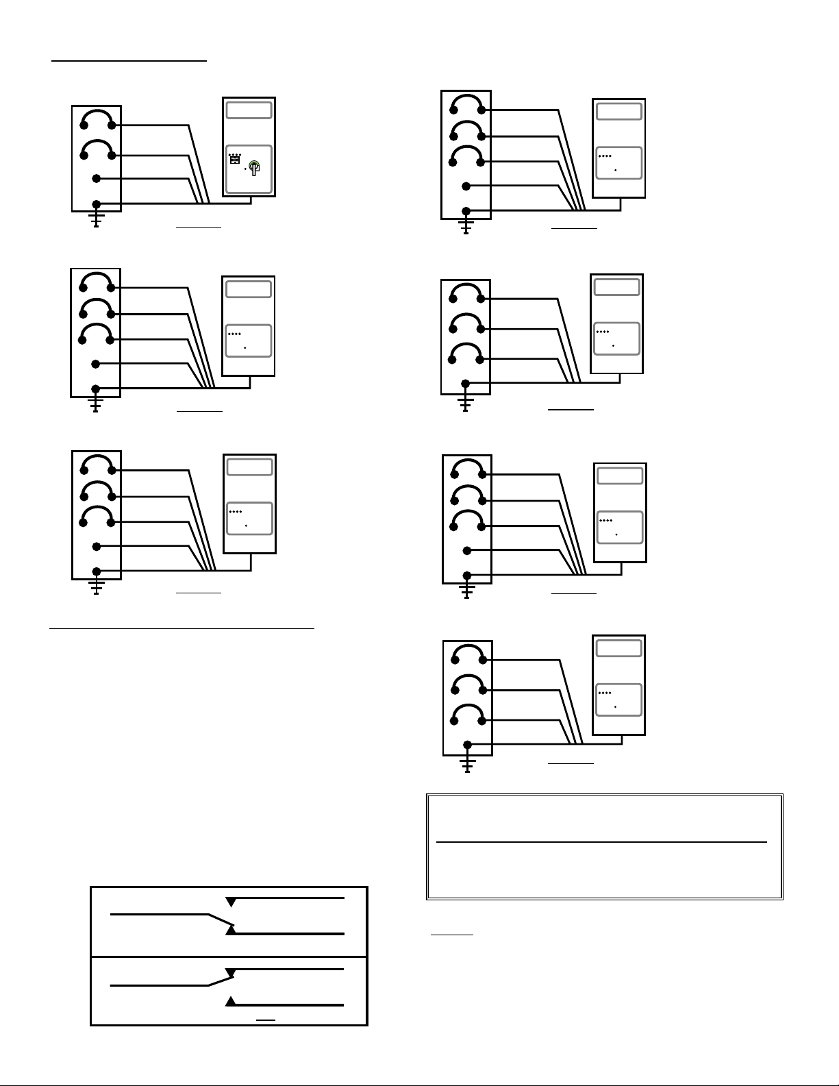
WIRING DIAGRAMS
120/240 VAC Single Phase
120/208 VAC Three Phase Wye
277/480 VAC Three Phase Wye
480 VAC Three Phase Delta
120/240 VAC Three Phase High Leg Delta
L1
L2
L3
N
G
L1
L2
L3
N
G
L1
L2
L3
N
G
L1
L2
N
G
L1
L2
L3
G
BLACK
BLACK
BLACK
WHITE
GREEN
BLACK
BLACK
BLACK
WHITE
GREEN
BLACK
BLACK
BLACK
GREEN
BLACK
RED
BLACK
WHITE
GREEN
BLACK
BLACK
WHITE
GREEN
Figure 1
Figure 5
Figure 3
Figure 4
L1
L2
L3
N
G
BLACK
BLACK
BLACK
WHITE
GREEN
Figure 2
NOTE: For convenience and working safety, these wiring
diagrams show installation on the load side of a breaker.
PG Series4000, 4500 and 5000 systems may be installed
without an external breaker. Refer to installation instruction number 4 on page 1.
MODELS:
PG4001-240-2S
PG4501-240-2S
PG5001-240-2S
MODELS:
PG4001-208-3Y
PG4501-208-3Y
PG5001-208-3Y
MODELS:
PG4001-600-3Y
PG4501-600-3Y
PG5001-600-3Y
MODELS:
PG4001-480-3Y
PG4501-480-3Y
PG5001-480-3Y
MODELS:
PG4001-480-3D
PG4501-480-3D
PG5001-480-3D
MODELS:
PG4001-240-3HLD
PG4501-240-3HLD
PG5001-240-3HLD
ALARM RELAY OUTPUT CONNECTIONS
1. Two Wire Closed Loop: Connect feed wire to the Common (C)
wire and return wire to the Normally Opened (N/O) wire. During
normal operation, the contact will be closed between C and N/O.
The contact will open during an alarm condition.
2. Two Wire Opened Loop: Connect the feed wire to the Common
( C ) wire and return wire to the Normally Closed (N/C) wire.
During normal operation, the contact will be opened between C
and N/C. The contact will close during an alarm condition.
3. Three Wire Supervised Loop: Connect feed wire to the
Common (C) wire, one return wire to the Normally Opened (N/O)
wire and the second return wire to the Normally Closed (N/C)
wire. During normal operation, the contact will be closed between
C and N/O and opened between C and N/C. An alarm condition
will reverse the condition.
4. Consult the instructions for your specific monitoring system for
additional information.
2
Brown - c
Brown - c
Violet - n/c
Orange - n/o
Orange - n/o
Violet - n/c
Normal operating condition - relay energized
Alarm condition - relay not energized
SUGGESTED WIRE SIZES
SERIES UNDER 3’ UNDER 6’ OVER 6’
PG4000 8 AWG 6 AWG 4 AWG
PG4500 6 AWG 4 AWG 2 AWG
PG5000 4 AWG 2 AWG 2 AWG
347/600 VAC Three Phase Wye
Figure 6
600 VAC Three Phase Delta
L1
L2
L3
G
BLACK
BLACK
BLACK
GREEN
Figure 7
MODELS:
PG4001-600-3D
PG4501-600-3D
PG5001-600-3D
OFF
SILENCENORMAL TEST
ON
SILENCENORMAL TEST
SILENCENORMAL TEST
SILENCENORMAL TEST
SILENCENORMAL TEST
SILENCENORMAL TEST
SILENCENORMAL TEST
Page 3

FINAL CHECKOUT PROCEDURE
1. Make sure that the Dead-front panel has been replaced and properly secured by replacing all bolts.
2. Make sure that the cover is closed and secured by all bolts.
3. Place alarm Alarm Switch in the NORMAL position.
4. Turn the PG Series disconnect switch to ON position.
5. RESTORE electric power to the PG Series circuit or equipment circuit.
6. Check all PROTECTION STATUS Line indicator lights for proper illumination.
7. Confirm that the PROTECTION STATUS Alarm indicator is OFF.
8. Check output continuity for the alarm relay. (a) Common to Normally Open = 0 ohms; (b) Common to Normally
Closed = greater than 10 M ohms.
9. Audible Alarm should be silent.
10. Place Alarm Switch in SILENCE position: Audible alarm should sound. Return Alarm Switch to normal position.
11. Place and hold Alarm Switch in TEST position. Audible alarm should sound and the alarm relay outputs should
reverse state. Release the switch and allow it to return to the NORMAL position.
OPERATION
1. The ALARM SWITCH should be in the NORMAL position for standard operating conditions.
2. The cabinet door must be closed and all bolts secured to prevent access by unauthorized personnel.
3. The PROTECTION STATUS Line indicator lights should be ON.
4. The PROTECTION STATUS Alarm indicator light should be OFF.
5. Periodic functional checks of the system as required by local codes or procedures are conducted by performing
steps 10 and 11 of the FINAL CHECKOUT PROCEDURE.
ALARM CONDITIONS
Alarm sounding and relay in “alarm state”
1. The audible alarm will sound and the alarm relay output will reverse state upon the loss of one or more protection
components.
2. Move the Alarm Switch to the SILENCE position. The local audible alarm will silence but the alarm relay output will
remain in the alarm condition until the unit is returned to normal operating condition.
3. Determine the cause of the alarm. One or more of the PROTECTION STATUS indicator lights may be off. Turn the
PG Series disconnect switch to the OFF position and open the cabinet door by removing the locking bolts.
4. Remove the deadfront panel and verify that the wiring is correct and secure. CAUTION: LINE VOLTAGE MAY BE
PRESENT AT THE INPUT SIDE OF THE DISCONNECT SWITCH.
5. Verify that the proper line voltage is present at the input side of the disconnect switch and the neutral and ground
busses.
6. Replace the deadfront panel and close and secure the cabinet door.
7. Turn the disconnect switch to the ON position. If the alarm condition does not clear, contact Intermatic Technical
Assistance for help.
Alarm not sounding but relay in “alarm state”
1. The alarm relay output will change state but the audible alarm will not sound under the following conditions:
]loss of power to the PG Series unit
]The disconnect switch is turned to the OFF position
]fault in the remote monitor system
2. Check for PROTECTION STATUS indicator light illumination. If all of the Line indicator lights are ON and the Alarm
indicator light is OFF, consult directions for trouble shooting the remote monitoring system.
TECHNICAL ASSIST
ANCE
For application or technical assistance contact Intermatic at 1-800-391-4555 or on the web at www.intermatic.com.
3
Page 4

TEN YEAR LIMITED PRODUCT WARRANTY
For
Intermatic PG Series SURGE PROTECTION DEVICES
(1) What Is Covered By This Limited Warranty
Repair or Replacement of Product
Intermatic Incorporated ("Intermatic") warrants to the original purchaser only, the Intermatic model PG4001-240-2S, PG4001-208-3Y,
PG4001-240-3HLD, PG4001-480-3Y, PG4001-480-3D, PG4001-600-3Y, PG4001-600-3D, PG4501-240-2S, PG4501-208-3Y,
PG4501-240-3HLD, PG4501-480-3Y, PG4501-480-3D, PG4501-600-3Y, PG4501-600-3D, PG5001-240-2S, PG5001-208-3Y,
PG5001-240-3HLD, PG5001-480-3Y, PG5001-480-3D, PG5001-600-3Y and PG5001-600-3D PanelGuardTMSurge Protection
Devices (each a "Product") shall be free from defects in material or workmanship for a period of ten years (120 months) from date of
purchase or 126 months from date of manufacture. If the purchaser discovers a defect in material or workmanship, the purchaser
must promptly submit a warranty claim. Upon a determination by Intermatic that the Product is defective, Intermatic shall correct any
defect in material or workmanship by, at Intermatic's option, either repairing or replacing the Defective Product. Any repair, including
both parts and labor, shall be at Intermatic's expense. The foregoing remedies are the purchaser's exclusive remedies for a breach
of warranty.
For purposes of this Limited Warranty, a Power Transient shall mean over-voltage resulting from momentary voltage spikes or
surges on an AC power line of magnitude that the Product, according to its specifications, is designed to stop before such spikes or
surges affect downstream equipment.
The Product must be installed in the appropriate application in complete accordance with the installation instructions. All building
wiring and other connections to the Product must conform to all applicable national, state and local electrical codes; the Product
must not be opened, modified, exposed to extreme heat or cold, submerged or subjected to abnormal use or service. All products
must be used in accordance with the instructions provided with the Product and the purchaser shall be solely responsible for selecting a Product model with specifications appropriate for the equipment to be protected. Intermatic shall determine, in its sole discretion, whether any Product returned by a purchaser has been used in accordance with its instructions, is an appropriate model for the
purchaser's use thereof, and whether the Product is defective.
(2) What Is Not Covered By This Warranty
Intermatic does not warrant (a) defects in the Product or damage to any equipment caused by the failure to properly install the
Product, (b) damage caused by use of the Product for purposes other than those for which it was designed, (c) damage caused by
disaster such as fire, flood and wind, (d) damage caused by unauthorized attachments or modification of the Product, (e) damage to
the Product occurring during shipment, or (f) damage caused by electrical disturbances exceeding published product specifications,
(g) damage to the Product caused by any other abuse or misuse by the purchaser.
(3) Disclaimer of Warranty
THE FOREGOING WARRANTIES ARE IN LIEU OF ALL OTHER EXPRESSED WARRANTIES. TO THE EXTENT ALLOWED BY
LAW, ANY IMPLIED WARRANTIES OF MERCHANTABILITY OR FITNESS FOR A PARTICULAR PURPOSE ARE LIMITED IN
DURATION TO THE DURATION OF THIS LIMITED WARRANTY.
(4) Limitation of Remedies
IN NO CASE SHALL INTERMATIC BE LIABLE FOR ANY SPECIAL, INCIDENTAL, OR CONSEQUENTIAL DAMAGES BASED
UPON BREACH OF WARRANTY, BREACH OF CONTRACT, NEGLIGENCE, STRICT TORT, OR ANY OTHER LEGAL THEORY.
SUCH EXCLUDED DAMAGES INCLUDE, BUT ARE NOT LIMITED TO, DAMAGE TO SOFTWARE, LOSS OF DATA, LOSS OF
PROFITS, LOSS OF SAVINGS OR REVENUE, LOSS OF USE OF THE PRODUCT OR ANY ASSOCIATED EQUIPMENT, COST
OF CAPITAL, COST OF ANY SUBSTITUTE EQUIPMENT, FACILITIES OR SERVICES, DOWNTIME, THE CLAIMS OF THIRD
PARTIES INCLUDING CUSTOMERS, DAMAGE TO PROPERTY AND PERSONAL INJURY. SOME STATES DO NOT ALLOW
LIMITS ON WARRANTIES OR ON REMEDIES FOR BREACH IN CERTAIN TRANSACTIONS. IN SUCH STATES, THE LIMITS IN
THIS PARAGRAPH AND IN PARAGRAPH (3) MAY NOT APPLY.
(5) T
ime Limit for Bringing Suit
No action arising out of any claimed breach of warranty may be brought more than one year after the cause of action has occurred.
(6) No Other Warranties
Unless modified in writing signed by both parties, this agreement is understood to be the complete and exclusive agreement
between the parties, superseding all prior agreements, oral or written, and all other communications between the parties relating to
the subject matter of this agreement. No employee of Intermatic or any other party is authorized to make any warranty in addition to
those made in this agreement.
INTERMATIC INCORPORATED
SPRING GROVE, ILLINOIS
http://www.intermatic.com
158PG10585 PDF 8.01
 Loading...