

Page 1
INSTALLATION
PF1000 SERIES
FREEZE PROTECTION CONTROLS
OPERATION &
SERVICE MANUAL
MODEL: PF1222TB1 SUBPANEL
TWO CIRCUIT POOL EQUIPMENT CONTROL WITH FREEZE AND HEATER PROTECTION
IN INDOOR/OUTDOOR ENCLOSURE
PANEL RATING: 60 AMP. 120/240 VOLT, 607 HZ.
Risk of drowning!
Do not permit unsupervised children to use pool or spa.
Close supervision of children required at all times.
WARNING
Turn power off at main panel before servicing this switch or the equipment it controls. This control panel must be
installed according to the National Electrical Code and local code requirements. Use MIN 75˚C Copper conductors ONLY.
Install interchangeable circuit breakers with an interrupting current rating of 10000 symmetrical amperes, or higher.
Follow manufacturers instructions for installing and testing of ground fault circuit breakers (GFCB) and interrupters
(GFCI). Install only LISTED receptacle(s) and/or wiring device(s) inside the enclosure. When panel is outdoors, a LISTED
rainproof cover must be installed over the wiring device in the side knockouts. This control should not be connected
to any equipment which would cause bodily injury or property damage should it be activated unexpectedly.
Reinstall safety guard after wiring.
Risk of Fire or Electrical Shock
DANGER
GENERAL INFORMATION
This Pool Equipment Control is designed to automatically operate the Filter Pump, Cleaner Pump and also to provide
freeze protection for the pool equipment. Nevertheless this product is not intended to be a substitute for insulation,
coverings, or maintenance.
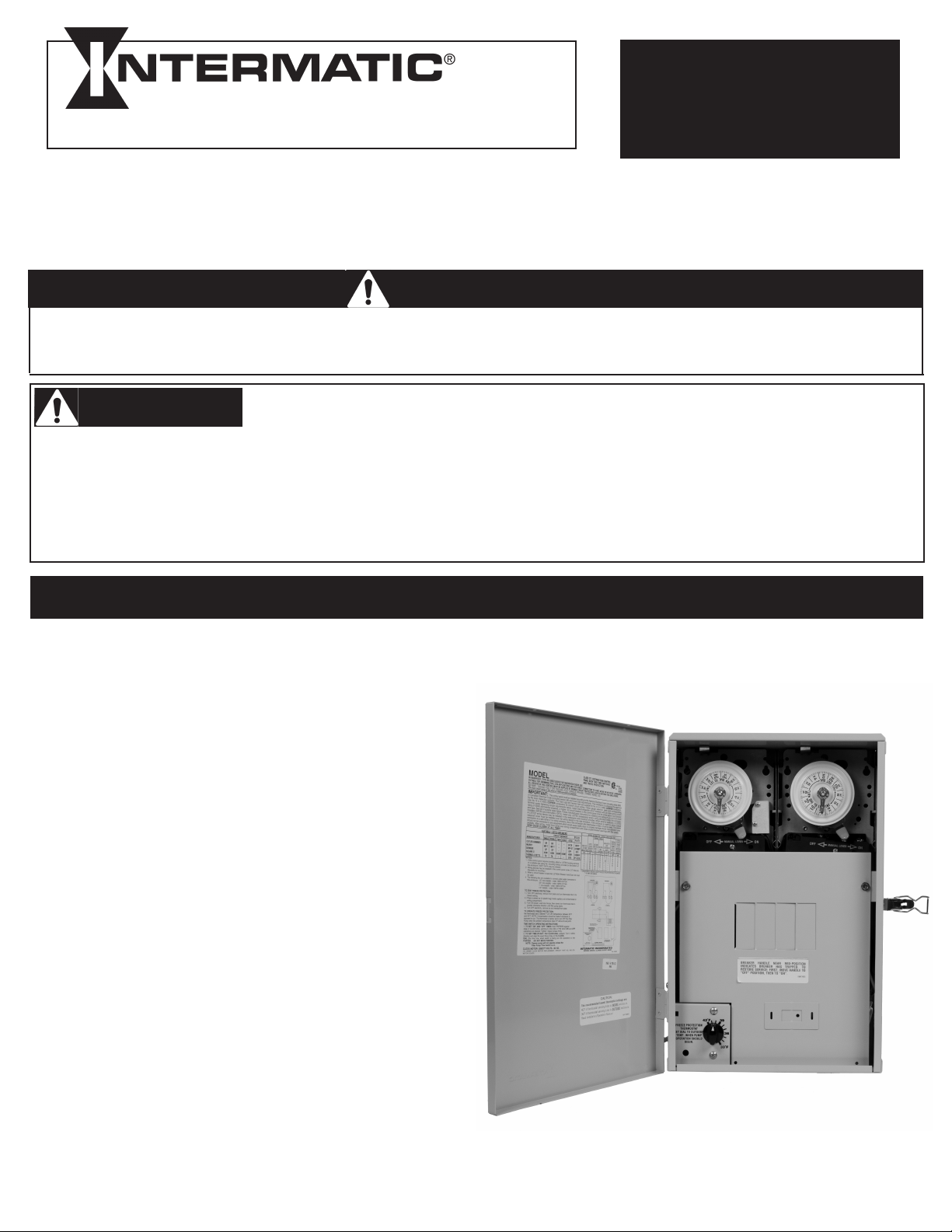
THE FILTER PUMP TIME SWITCH is located in the upper
left side of the enclosure and operates the Filter Pump, as
set by the trippers on the yellow dial, on a 24 hour
schedule. For setting the schedule, refer to page 3 of this
Manual.
THE FIREMAN SWITCH (heater protection mechanism) is
located next to the manual lever and its function is to stop
the heating process 20 minutes before the Time Switch
turns OFF the Filter Pump. By doing so, the circulating
water cools the heat exchanger thus preventing excess
heat build-up.
THE CLEANER PUMP TIME SWITCH is located in the
upper right side of the enclosure and operates the Cleaner
Pump (Booster Pump). The trippers of this Time Switch
should be set so that the operation of the Cleaner Pump
falls within the operation of the Filter Pump. To avoid
equipment damage, the two Time Switches are interlocked
and the Cleaner Pump would not operate unless the Filter
Pump is already operating.
THE FREEZE PROTECTION THERMOSTAT is located in
the lower left side of the enclosure and turns ON the Filter
Pump when the air temperature (where the Control Panel
is located) drops below the temperature set by the dial
(between 33˚F and 42˚F).
Page 2
CAUTION
Risk of injury or property damage!
Do not install or operate this equipment and other associated equipment without basic safety
precautions.
Read and follow the safety instructions listed below and other basic safety precautions before
installation or operation of this control and other associated equipment.
1. This control must be installed by a qualified person, according to the national and local electrical
codes.
2. Install this control not less than 5 feet (3 meters in Canada) from inside edge of pool and 1 foot
(30cm) above ground.
3.USECOPPERCONDUCTORSONLYrated75˚Cminimum.
4. Do not exceed maximum ratings of individual components, wiring devices and current carrying
capacity of conductors.
5. For control grounding, bonding, installing and the wiring of underwater lights, refer to Article 680
of the National Electrical Code or Article 68 of the Canadian Electrical Code.
6. The control should not operate any equipment which would cause bodily injury or property
damage should it be activated unexpectedly.
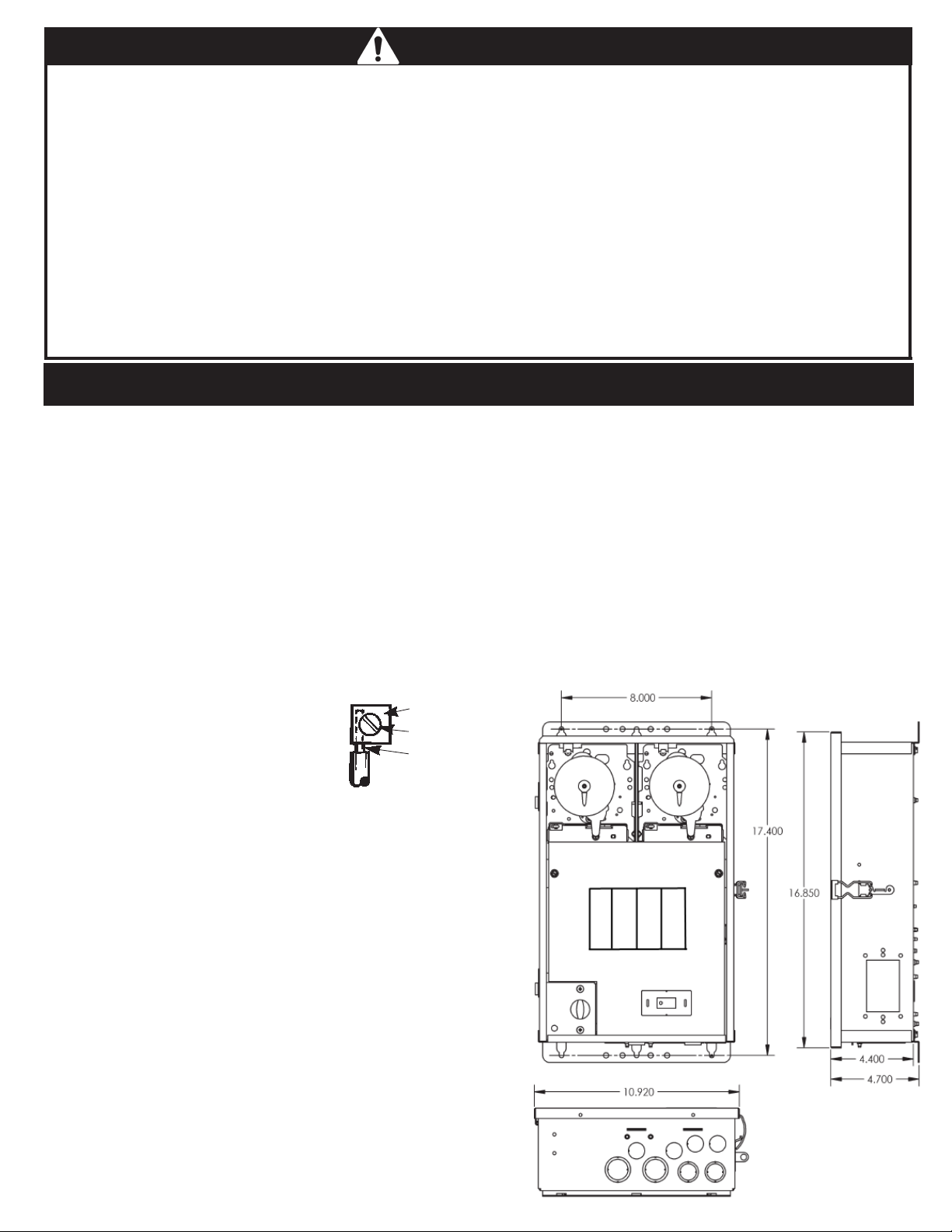
INSTALLATION
1. Select the proper location for the Control Panel and
prepare the necessary conduit run(s) required by the
installation layout.
2. Remove the four #10 hex head screws from the back
of the enclosure and attach mounting brackets to
enclosure.
3. Hang enclosure on a flat vertical surface or other
support, using hardware suitable for the purpose.
4. Properly terminate conduits at both ends and pull-in
the conductors as specified by the installation layout.
5. Follow wiring diagram on page 4, connect 240 Volt
Supply to LINE 1, LINE 2, NEUTRAL (if needed) and
EQUIPMENT GROUND to the terminals so indicated.
PRESSURE
6. Insert a 20 or 30 Amp 240 Volt
circuit breaker into the Breaker Base
and connect leads to Terminal TB1 on
the left, see insert for proper termination.
7. Connect Filter Pump leads to terminals 2
and 4 of Filter Pump Time Switch and
Cleaner Pump leads to terminals 2 and 4 of Cleaner
Pump leads to terminals 2 and 4 of Cleaner Pump Time
Switch. Connect the grounding leads of each pump to
the Equipment Grounding Terminal at the bottom of the
enclosure.
PLATE
TERMINAL
SCREW
MAKE SURE
INSULATION
CLEARS
PRESSURE
PLATE
11. TEST INSTALLATION:
a. Turn the thermostat dial to its lowest setting and
place crushed ice (in plastic bag) inside capillary coil
of Thermostat.
b. Turn ON power to Control Panel, wait 20 seconds
then slowly turn thermostat dial counter-clockwise
until Filter Pump starts.
c. Using the manual lever on Cleaner Time Switch,
turn ON-OFF the Cleaner Pump.
d. Turn OFF power to Control Panel, remove ice,
check wiring, tighten terminal screws if necessary,
reinstall time switch insulators and front plate.
e. Turn ON power to Control Panel and set time
Switches and the Thermostat, see OPERATION
instructions on page 3.
8. If the Control Panel is installed in location, where it is
exposed to direct sun most of the day, extend 8 inches
of the copper capillary tube of the thermostat into an
open ended (plastic or metal) conduit, about 10 inches
long, installed at bottom of the enclosure. Handle
capillary tube with care!.
9. If external bonding is required, install a bonding lug at
bottom of enclosure and bond installation according to
code requirements.
10. If required by the heater manufacturer, follow his
instructions and make the fireman switch connections.
Use at least #18 AWG wiring with insulation rated 300
Volt or higher. Connect heater ON/OFF switch in series
with the fireman Switch and turn switch on heater to
ON.
Figure 1
2
Page 3

OPERATION
TO SET FILTER TIME SWITCH, follow instructions on
the right. The length of the daily filtration/heating cycle
depends on many variables such as size, shape, and
geographic location of the pool, water chemistry, type
of pool equipment, usage and season of year. If not
sure, contact your local pool service professional for advice.
TO SET CLEANER TIME SWITCH, follow instructions
on the right. NOTE: This Control is factory wired to
prevent equipment damage by allowing the Cleaner
Pump to operate only when the Filter Pump is already
operating. This requires that the Cleaner Time Switch
settings (ON and OFF times) must be within the
operating hours of the Filter Pump. For example: If the
Filter Pump is set to operate from 8 am to 2 pm daily,
the Cleaner Pump Time Switch should be set to
operate no longer than 8:30 am to 1:30 pm.
TIME SWITCH OPERATING INSTRUCTIONS
1. TO SET “ON” AND “OFF” TIMES: Hold TRIPPERS
against edge of CLOCK-DIAL, pointing to time (AM or
CLOCK
DIAL
TIME
POINTER
OFF
TRIPPER
MANUAL
LEVER
now, when switch is being put into operation) to the
POINTER. DO NOT MOVE POINTER
• TO OPERATE SWITCH MANUALLY: Move
MANUAL LEVER below CLOCK-DIAL left or right as
indicated by arrows, This will not affect next
operation.
• FOR MORE THAN ONE DAILY ON-OFF
OPERATION: Place additional tripper pairs on CLOCK-
DIAL (order 156T1978A).
• IN CASE OF POWER FAILURE, reset CLOCK-DIAL
to proper time-of-day. See step 2 above.
PM) when ON and OFF operations
are desired. Tighten tripper screws
firmly.
2. TO SET TIME-OF-DAY: Pull
ON
CLOCK-DIAL outward. Turn in either
TRIPPER
direction and align the exact time-ofday on the CLOCK-DIAL (the time
TO SET THERMOSTAT, turn dial, pointing to desired temperature, marked on the plate, between 32˚F
and 45˚F. Again, many variables must be considered before selecting the “turn ON” temperature of the
Filter Pump and your local pool service professional is the best source of information. The Thermostat is
factory set to turn OFF the Filter Pump when the ambient temperature rises 5˚F above its set point.
THE FIREMAN SWITCH (Heater Protection Mechanism), if installed, is factory set and shuts OFF
the heater 20 minutes before the Time Switch turns OFF the filter pump. The Fireman Switch
requires no setting or service.
TROUBLESHOOTING
SYMPTOM CAUSE(S) CORRECTIVE ACTION
1. Time Switch will not keep 1a. Frequent power outages Reset dial
time - dial is turning. 1b. Wrong voltage/cycle Change clock motor
1c. Loose clock motor connections Check connections
2. Time Switch Dial stops 2a. Loose tripper Check/change tripper
at ON or OFF tripper. 2b. Bent dial Check/change mechanism
2c. Defective motor Change clock motor
3. Load is ON at all times-- 3a. Welded contacts Change mechanism
dial is turning. 3b. Two ON-trippers on dial Change tripper
3c. No OFF tripper on dial Change tripper
3d. Defective mechanism Change mechanism
4. Dead clock motor. (Clock 4a. Defective clock motor (open Change clock motor
motor gears do not rotate.) coil due to lightning or surge)
4b. Loose clock motor connections Check connections
4c. Wrong voltage Change clock motor
5. Filter Pump will not start 5a. Defective thermostat Replace thermostat
when temp. is below 32˚F. 5b. Defective relay Replace relay
5c. Faulty wiring Check wiring
5d. Power outage Install stand-by power
3
Page 4

WIRING
DIAGRAM
NOTE: Ground connections
are not shown and
vary with installation.
Filter Control
Time Switch
To Filter
Pump
240 V.
Clock
Motor
TB1
Team
Block
Fireman
Switch
To
Heater
Cleaner Control
Time Switch
Line 2
240 V.
Clock
Motor
To Cleaner
Pump
Relay
T. Stat
ALTERNATE WIRING FOR
TWO INDEPENDENTLY
WIRED PUMPS
See Note 6
on Page 2
Breaker Base
Line 1
Neutral
Equipment Ground
If within the warranty period specified, this product fails due to a defect in
material or workmanship, Intermatic Incorporated will repair or replace it, at its
sole option, free of charge. This warranty is extended to the original household
purchaser only and is not transferable. This warranty does not apply to: (a)
damage to units caused by accident, dropping or abuse in handling, acts of
God or any negligent use; (b) units which have been subject to unauthorized
repair, opened, taken apart or otherwise modified; (c) units not used in
accordance with instructions; (d) damages exceeding the cost of the product;
(e) sealed lamps and/or lamp bulbs, LED’s and batteries; (f) the finish on any
portion of the product, such as surface and/or weathering, as this is considered
normal wear and tear; (g) transit damage, initial installation costs, removal
costs, or reinstallation costs.
INTERMATIC INCORPORATED WILL NOT BE LIABLE FOR INCIDENTAL
OR CONSEQUENTIAL DAMAGES. SOME STATES DO NOT ALLOW THE
EXCLUSION OR LIMITATION OF INCIDENTAL OR CONSEQUENTIAL
DAMAGES, SO THE ABOVE LIMITATION OR EXCLUSION MAY NOT
APPLY TO YOU. THIS WARRANTY IS IN LIEU OF ALL OTHER EXPRESS
OR IMPLIED WARRANTIES. ALL IMPLIED WARRANTIES, INCLUDING THE
WARRANTY OF MERCHANTABILITY AND THE WARRANTY OF FITNESS
FOR A PARTICULAR PURPOSE, ARE HEREBY MODIFIED TO EXIST ONLY
AS CONTAINED IN THIS LIMITED WARRANTY, AND SHALL BE OF THE
SAME DURATION AS THE WARRANTY PERIOD STATED ABOVE. SOME
STATES DO NOT ALLOW LIMITATIONS ON THE DURATION OF AN IMPLIED
WARRANTY, SO THE ABOVE LIMITATION MAY NOT APPLY TO YOU.
This warranty service is available by either (a) returning the product to the
dealer from whom the unit was purchased or (b) completing a warranty
claim online at www.intermatic.com. This warranty is made by: Intermatic
Incorporated, Customer Service 7777 Winn Rd., Spring Grove, Illinois
60081-9698. For warranty service go to: http://www.Intermatic.com or call
815-675-7000.
LIMITED ONE YEAR WARRANTY
Because of our commitment to continuing research and improvements, Intermatic Incorporated reserves the right to make
changes, without notice, in the specifications and material contained herein and shall not be responsible for any damages,
direct or consequential, caused by reliance on the material presented.
158--01294
INTERMATIC INCORPORATED, SPRING GROVE, IL. 60081-9698
4
 Loading...