

Page 1

INSTALLATION
INSTRUCTIONS
IG 1300 Series
CAUTION !
Electricity is dangerous if safety rules
are not followed. Never work on equipment with the electricity turned 'ON'. Be
absolutely certain the power is turned
‘OFF' on the circuit or device you are
installing or repairing. If you are not
able to determine that power is removed
have it checked by a licensed electrician. Be sure you read carefully and
understand all of these installation steps
and have the necessary tools and supplies before you begin to install the protector. Check and follow your local elec-
trical codes, they are for your protection.
When installing outdoors, care must be taken to comply with all local and national electric codes regarding outdoor or wet locations. Do not touch electric devices when you
are wet or you are standing on a wet surface. Use a circuit tester or AC voltmeter to be
sure the electricity is "OFF' before you touch wires or devices.
Install Telephone protection per Article 800 of the National Electrical Code on the equipment side of the primary telephone Listed equipment.
NOTE:
ELECTRICAL GROUND IS REQUIRED FOR THIS UNIT TO
FUNCTION PROPERLY AND SAFELY!
STEP 1
Verify that all parts are included for your system.
DESCRIPTION QUANTITY QUANTITY
(IG1300-2T-1C) (IG1300-4T-2C)
PanelGuard IG1300 AC Voltage Protection Device 1 1
with 30” wire leads
Mounting Plate 1 1
Wire channel cover 1 1
4-wire (2-pair) Telephone protection module 1 2
1-circuit coaxial cable protection module 1 2
STEP 2
Tools and additional materials required.
AC Voltmeter or Voltage tester
Screwdrivers
Flat or phillips blade for cabinet mounting screws.
Torx T-20 for internal screws
Lineman’s pliers or wire strippers
Hammer (optional)
3 each 1-1/4” x #10 sheet metal, wood or masonry screws
Page 2

STEP 3
Select a location for the Surge Protection Device (SPD) which will allow con-
venient connection to the panel while keeping the lead wires as short as possible. Use an AC voltmeter or circuit tester across two breaker outputs to confirm that there is 240 volts between them. If the voltage is 0, select a different
breaker or pair of breakers and retest for the presence of 240 volts. A two-pole
or two single-pole breakers of no larger than 20 amp capacity should be used.
STEP 4
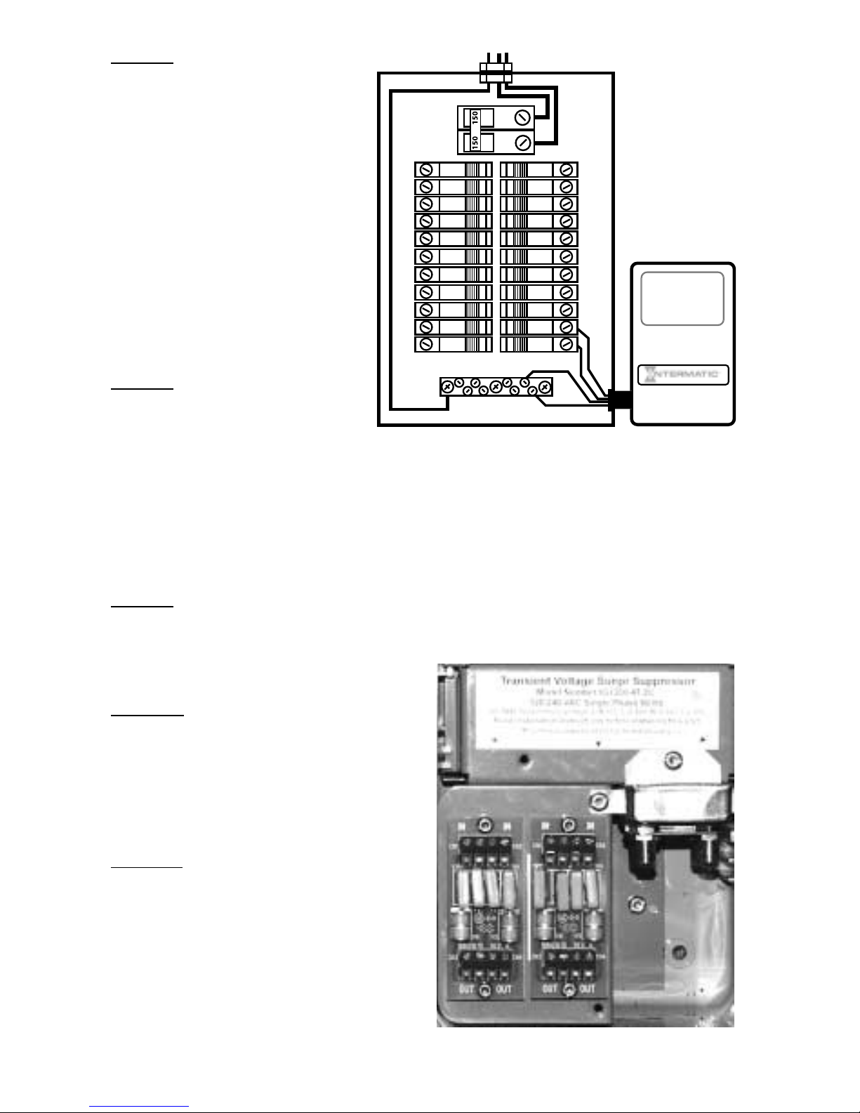
Select a mounting position for the protector at the electric panel. If you have
a panel that is not similar to the diagram in Figure 2, call Intermatic for assistance at the numbers listed at the end of these instructions between the hours
of 8:00 am and 4:00 pm central time Monday through Friday.
Note
: Operation of the IG1300 Series will be optimized by keeping the wire
lead lengths as short and balanced as possible. It is better to use two breakers near the bottom of the electrical panel with short wire leads than to use
two breakers at the top of the panel with long wire leads.
STEP 5
Prepare the protector for installation. Open the cover of the NEMA 3R cabi-
net and remove the screws from holes A and B using a Torx T-20 screwdriver
or bit.
STEP 6
Lift the telephone and coaxial protection module assembly out of the cab-
inet and place it to one side for future use. Straighten the four 14 AWG wires
and let them hang.
Figure 1
Torx T-20
in Hole A
Torx T-20
in Hole C
Hole D
Hole F
Torx T-20 in
Hole B
(hole E
located under wire
channel cover
AC Voltage
Protection Device
Mounting Plate
4-wire Telephone
protection modules
Coaxial Cable
protection module
Mounting Screw
Hole (second hole
located under wire
channel cover)
Mounting Screw
Keyhole
2
Wire Channel
Cover
Page 3
STEP 7
Position the protector on the
wall next to the electrical panel
and mark the position of the the
cabinet mounting holes on the
wall. Care should be exercised
to position the knockout in the
protector cabinet in line with a
knockout in the electrical panel.
At least 2” should be allowed
between the protector and the
electrical panel to allow the
cover to open. Predrill the holes
and set one screw in the hole
for the top mounting screw.
STEP 8
Remove the appropriate
knockout from the protector
cabinet. Install a 2-1/2” nipple,
length of seal-tite or conduit
between the protector and electrical cabinets. Hang the protector cabinet on
the screw using the exterior top keyhole of the cabinet. Insert the remaining
two mounting screws through the holes in the protector cabinet and tighten all
of the cabinet mounting screws. Tighten the connectors on the nipple, seal-tite
or conduit between the cabinets.
STEP 9
Make sure that the electric power is OFF in the electrical panel. Remove
the front cover or trim panel from the panel. Select and remove the desired
knockout through which the protector
wiring will enter the panel.
STEP 10
Twist the four 14 AWG wires around
each other at a rate of 1-1/2 turns per
foot of length. Wrap a piece of tape on
the ends of the wires and feed them
through the connector and into the
electrical panel.
STEP 1
1
The IG1300 Series is shipped ready
for installation on the right-hand side
or top positions of the electrical panel.
If the protection panel is mounted on
the left side of the electrical panel,
refer to the Special Instructions at
the end of this section to reverse the
wire channel cover and telephone and
coaxial modules.
Figure 3
3
Figure 2
Page 4

Replace the telephone and coaxial protection module assembly that was
removed in Step 6. Replace the Torx screws in holes A and B that were
removed in Step 5. Tighten the screws firmly to ensure a good ground bond.
STEP 12
Select and remove the appropriate knockout to use with telephone and
coaxial cables. Use a knockout that is accessible after the wire channel cover
has been reinstalled. DO NOT route telephone or coaxial cables through the
same knockout or conduit with AC power wires. If conduit is used, it is important to keep telephone and cable conductors in a different conduit than AC
power conductors.
STEP 13
Identify and confirm wire pairs for each telephone line. Make sure that
enough wire is available to reach each terminal block on the telephone protection modules. Cut each wire pair and strip the end to a length of 5/16”. Route
the wires through the knockout and insert the stripped end of each wire into
the terminal blocks as shown in Figure 3. Be sure to route the wires from the
outside phone connection to the “IN” terminal and the wires to the house
phones to the “OUT” terminal. Secure each wire by tightening the terminal
block screws. NOTE: Exercise caution to ensure that each wire of a telephone
pair is in line to prevent polarity reversal.
STEP 14
Route the coaxial cable through the knockout. If insufficient space is avail-
able in the knockout, the second knockout may be used. Connect the cable to
the protection module making sure that the connectors are tightened snugly.
Do not overtighten the connectors.
STEP 15
Connect the AC Power protection to the electrical panel. Measure each wire
lead and cut it to proper length. Each wire should be as short as possible to
provide optimum operation. Do Not coil excess lead.
NOTE: The protector functions best if all bends in the wire leads are rounded,
ideally to a 4” radius. Hard 90obends reduce efficiency.
Connect the Green Ground wire to the panel ground bus first. Connect the
White Neutral wire to the Neutral bus if the electrical panel has one. Many
panels have a common Neutral and Ground bus which will result in both the
Green and White wires connecting to the same bus.
STEP 16
Connect the two black wires to two separate 15 or 20 amp single-pole cir-
cuit breakers.
STEP 17
Check to be sure that all wires are securely fastened and all screws are
tight. Confirm that the protector is wired to the correct breakers by measuring
the voltage between the two black leads. A voltage of 220 to 240 VAC means
that the IG1300 is connected across both sides of the electrical service.
STEP 18
Replace the cover or trim panel on the electrical cabinet. Return all breakers
to their original positions and check the IG1300 for two green indicators.
4
Page 5

STEP 19
Close the cover on the IG1300.
SPECIAL INSTRUCTIONS
Use the following steps when installation requires placing the IG1300 on the
left side of the electrical panel.
STEP A
Loosen the screw in hole C that secures the coaxial cable protection
module(s) to the wire channel cover. Remove the coaxial modules and set
them to one side for future use. Remove screw C completely.
STEP B
Invert the wire channel cover with the telephone line protection modules still
attached to it and place it into
the IG1300 cabinet as shown
in Figure 4. Install a Torx
screw through the hole in the
foot of the wire channel cover
and into hole E and tighten it
snugly to the back of the cabinet.
STEP C
Insert a Torx screw through
the elongated hole on the
coaxial protection module(s)
and into hole D as shown in
Figure 4. Do not tighten the
screw.
STEP D
Place the remaining Torx
screw through the opening on
the tab of the coaxial protection module(s) and into hole F.
Tighten the Torx screws firmly
to ensure a good ground
bond.
NOTE:
If the telephone protection Modules are left in an inverted position as shown in
figure 4, be sure to observe the “IN” and “OUT” markings.
STEP E
Return to Step 12.
Figure 4
5
Torx T-20
in Hole E
Torx T-20
in Hole D
Torx T-20
in Hole F
TROUBLESHOOTING and ASSISTANCE:
Technical Services 815-675-7000
http://www.intermatic.com
Page 6

INTERMA TIC IG1300 SERIES
FIVE YEAR LIMITED PRODUCT and CONNECTED EQUIPMENT W ARRANTY
(
1) What Is Covered By This Limited Warranty
(A) Repair or Replacement of Product
Intermatic Incorporated ("Intermatic") warrants to the original purchaser only , the Intermatic IG13002T-1C or IG1300-4T-2C Surge Protection Devices (each a "Product") shall be free from defects in
material or workmanship for a period of five years (60 months) from date of purchase or 66 months
from date of manufacture. If the purchaser discovers a defect in material or workmanship, the purchaser must promptly submit a warranty claim. Upon a determination by Intermatic that the
Product is defective, Intermatic shall correct any defect in material or workmanship by , at
Intermatic's option, either repairing or replacing the Defective Product. Any repair, including both
parts and labor, shall be at Intermatic's expense. The foregoing remedies are the purchaser's
exclusive remedies for a breach of warranty .
The Product must be installed in the appropriate application in complete accordance with the installation instructions. All building wiring and other connections to the Product must conform to all
applicable national, state and local electrical codes; the Product must not be opened, modified,
exposed to extreme heat or cold, submerged or subjected to abnormal use or service. All products
must be used in accordance with the instructions provided with the Product and the purchaser shall
be solely responsible for selecting a Product model with specifications appropriate for the equipment to be protected. Intermatic shall determine, in its sole discretion, whether any Product
returned by a purchaser has been used in accordance with its instructions, is an appropriate model
for the purchaser's use thereof, and whether the Product is defective.
(B) Repair or Reimbursement for Damage to Properly Connected Equipment
In addition to the above described Product warranty , Intermatic warrants to the original purchaser of
the Product for a period of five years from the date of purchase, the following: In the event that any
major household connected electrical equipment (as defined below) is damaged (the "Damaged
Equipment") as a direct result of the failure of a Product to protect the Damaged Equipment from
Power Transients (as hereinafter defined) and all of the conditions are satisfied, Intermatic shall, at
Intermatic's option, either repair the Damaged Equipment or reimburse the purchaser of the defective product. The limit of Intermatic's liability under this warranty shall be the Fair Market V alue (as
hereinafter defined) of the Damaged Equipment or the deductible amount of the original purchaser's homeowner's insurance policy , whichever is less. In no event shall Intermatic incur repair costs
or reimburse the purchaser for an amount in excess of Ten Thousand Dollars ($10,000.00).
As used herein, "major household connected electrical equipment" shall mean major household
appliances and electronic devices, including refrigerators, freezers, air conditioners, stoves and
ovens, microwave ovens, clothes washers and/or dryers, dishwashers, audio and stereo equipment or components, video equipment, televisions and computers. Major household connected
electrical equipment that normally requires an additional connection such as phone/modem connection, antenna or cable connection or other temporary or permanent connection must be properly connected to the Intermatic IG1300 Series Surge Protection Device that incorporates surge protection for both the AC (power) and all other input connections. If this is not physically possible, then
all input connections for any specific piece of equipment must be properly connected to an
Intermatic UL listed Surge Protection Device that incorporates surge protection for both the AC
(power) and all other input connections. The Fair Market V alue of the Damaged Equipment shall
be the current value of the equipment specified in the most recent version of the Orion Blue Book
(printed or on-line edition) by Orion Research Corporation, or a comparable publication.
Promptly upon discovering any Damaged Equipment, the purchaser must submit a claim pursuant
to the claim procedure provided below. In no event may a purchaser initiate a claim later than (30)
days after the Protected Equipment is damaged. In order to receive the Connected Equipment pro-
6
Page 7

tection provided in this Section, all of the following conditions must be satisfied with respect to the
use of the Product: (a) the Product must be properly installed; (b) all building wiring and other connections to the Product and the Damaged Equipment must conform to all applicable federal, state
and local electrical codes; (c) no ground wires or ground connections in addition to the AC power
source can be used in connection with the Product or the Damaged Equipment; (d) Equipment
with additional wiring or data/cable connections (as defined above) must be properly connected to a
UL listed Surge Protection Device (as noted above); and (e) the Product(s) and Protected
Equipment must not be opened, modified, exposed to extreme heat or cold, submerged or subjected to abnormal use or service.
For purposes of this Limited Warranty, a Power Transient shall mean over-voltage resulting from
momentary voltage spikes or surges on an AC power line of magnitude that the Product, according
to its specifications, is designed to stop before such spikes or surges affect downstream equipment.
(2) What Is Not Covered By This W
arranty
Intermatic does not warrant (a) defects in the Product or damage to any equipment caused by the
failure to properly install the Product, (b) damage caused by use of the Product for purposes other
than those for which it was designed, (c) damage caused by disaster such as fire, flood and wind,
(d) damage caused by unauthorized attachments or modification of the Product, (e) damage to the
Product occurring during shipment, (f) electrical disturbances exceeding published product specifications, (g) damage to the Product caused by any other abuse or misuse by the purchaser.
This warranty applies to residential use of Intermatic IG1300 Series and excludes any commercial
applications. This device is not intended to provide protection during Utility voltage swells or loss of
neutral conditions which are by definition not transient events and are not covered by this warranty .
(3) Disclaimer of W
arranty
THE FOREGOING WARRANTIES ARE IN LIEU OF ALL OTHER EXPRESSED WARRANTIES. TO THE EXTENT ALLOWED BY LA W, ANY IMPLIED WARRANTIES OF MERCHANT ABILITY OR FITNESS FOR A PARTICULAR PURPOSE ARE LIMITED IN DURA TION
TO THE DURATION OF THIS LIMITED WARRANTY.
(4) Limitation of Remedies
IN NO CASE SHALL INTERMA TIC BE LIABLE FOR ANY SPECIAL, INCIDENTAL, OR CONSEQUENTIAL DAMAGES BASED UPON BREACH OF WARRANTY, BREACH OF CONTRACT, NEGLIGENCE, STRICT TORT, OR ANY OTHER LEGAL THEORY. SUCH EXCLUDED DAMAGES INCLUDE, BUT ARE NOT LIMITED TO, DAMAGE TO SOFTWARE, LOSS OF
DA TA, LOSS OF PROFITS, LOSS OF SA VINGS OR REVENUE, LOSS OF USE OF THE
PRODUCT OR ANY ASSOCIA TED EQUIPMENT, COST OF CAPITAL, COST OF ANY SUBSTITUTE EQUIPMENT, FACILITIES OR SERVICES, DOWNTIME, THE CLAIMS OF THIRD
P ARTIES INCLUDING CUST OMERS, DAMAGE TO PROPERTY AND PERSONAL INJURY .
SOME ST ATES DO NOT ALLOW LIMITS ON WARRANTIES OR ON REMEDIES FOR
BREACH IN CERT AIN TRANSACTIONS. IN SUCH STA TES, THE LIMITS IN THIS PARAGRAPH AND IN P ARAGRAPH (3) MAY NOT APPLY .
(5) T
ime Limit for Bringing Suit
No action arising out of any claimed breach of warranty may be brought more than one year after
the cause of action has occurred.
(6) No Other W
arranties
Unless modified in writing signed by both parties, this agreement is understood to be the complete
and exclusive agreement between the parties, superseding all prior agreements, oral or written,
and all other communications between the parties relating to the subject matter of this agreement.
No employee of Intermatic or any other party is authorized to make any warranty in addition to
those made in this agreement.
7
Page 8

(7) Claim Procedure
In order to submit a claim for warranty service the purchaser must:
(A) Contact the Intermatic Insurance Claims Center at 1-800-270-7227 before having the
damaged equipment repaired.
(B) Request that an Incident Claim Report be written regarding the damage including
descriptions and model identification (if available) of the equipment that was damaged.
Record the W
arranty Claim Number for future reference.
(C) File a claim for the damaged equipment with your homeowner’s (or renter”s) insurance company .
(D) Send the INTERMA TIC® IG1300 Series Surge Protection Device to the
INTERMA TIC
WARRANTY COORDINA TOR at the address listed below. All returned devices must be plainly
marked with the INTERMA TIC WARRANTY CLAIM NUMBER.
(E) Send all of the following information in a single packet to the
INTERMA TIC WARRANTY
COORDINA TOR
at the address listed below .
(1) Claimant’s name, address and telephone number
(2) Original dated sales receipt for the Intermatic IG1300 Series Protection Device
(3) Original report for repair work
(4) The damage report
(5) A copy of the claim report by the homeowner’s (renter’s) insurance company or a
copy of the policy showing the deductible amount exceeds the cost of the repair .
(F) Address all communications and product returns to:
I
NTERMA TIC WARRANTY COORDINA T OR
7777 WINN ROAD,
SPRING GROVE, ILLINOIS 60081
ATTN: SURGE CLAIM PROCESSOR
PRODUCT & INSTALLATION INFORMATION
Purchase date:
Installation date:
Installed by:
INTERMATIC INCORPORATED
SPRING GROVE, ILLINOIS
http://www.intermatic.com
158IG10842
 Loading...