

Page 1
DE
Bedienungsanleitung 2
EN
Operating manual 14
FR
Notice d‘utilisation 26
IT
Manuale operativo 38
ES
Instrucciones de
manejo
PT
Instruções de uso 62
NL
Bedieningshandleiding
CS
Návod k obsluze 86
50
74
SV
Användningsinstruktion
NO
Betjeningsanvisning 110
DA
Betjeningsvejledning 122
FI
Käyttöopas 134
PL
Instrukcja obsługi 146
HU
Kezelési utasítás 158
Registration numbers 170
talento smart
98
B10 m ini
Page 2

Diese Anleitung ermöglicht den sicheren und efzienten Umgang mit der Verteilerschaltuhr (im Fol-
genden „Gerät“). Diese Anleitung ist Bestandteil des Geräts und muss für jeden, der mit dem Gerät
umgeht, jederzeit zugänglich aufbewahrt werden. Jeder, der mit dem Gerät umgeht, muss diese Anleitung vor Beginn aller Arbeiten sorgfältig durchgelesen und verstanden haben. Grundvoraussetzung für
sicheres Arbeiten ist die Einhaltung aller angegebenen Sicherheitshinweise und Handlungsanweisungen in dieser Anleitung.
Urheberschutz
Diese Anleitung ist urheberrechtlich geschützt.
Die Überlassung dieser Anleitung an Dritte, Vervielfältigungen in jeglicher Art und Form – auch auszugsweise – sowie die Verwertung und/oder Mitteilung des Inhaltes sind ohne schriftliche Genehmigung des Herstellers, außer für interne Zwecke nicht gestattet. Zuwiderhandlungen verpichten zu
Schadenersatz. Der Hersteller behält sich das Recht vor, zusätzliche Ansprüche geltend zu machen.
Das Urheberrecht liegt beim Hersteller.
Download
Folgende Informationen nden sich unter www.graesslin.de:
Anleitung zum Download und Technische Daten
2
Page 3
DE
Konformitätserklärung
Hiermit erklärt Grässlin GmbH, dass der Funkanlagentyp „talento smart B10 mini“ der Richtlinie
2014/53/EU entspricht. Der vollständige Text der EU-Konformitätserklärung ist unter der folgenden
Internetadresse verfügbar: http://qrc.graesslin.de/talento-smart-conformity
Übersicht ................................................................................................. 4
Sicherheit ............................................................................................... 10
Installation ............................................................................................. 12
Entsorgung ............................................................................................ 13
3
Page 4

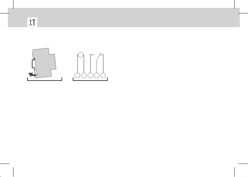
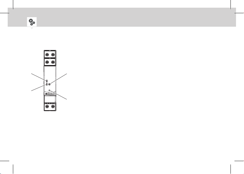
Übersicht
5
5
5
1
2
3
1
4
5
6
Abb. 1: Verteilerschaltuhr
4
Klicksystem für Montage auf DIN-Schiene
2
Anschlussklemmen für Kanal 1
3
Potentialfreie Leerklemme
4
LED 1
5
Bedientaste
6
LED 2
Reset-Taste
Anschlussklemme Neutralleiter
Anschlussklemme Phase
Page 5
DE
Funktionsbeschreibung
Die Verteilerschaltuhr ist eine Schaltuhr, die mit einem Klicksystem auf eine DIN-Schiene (Abb. 1/
1
)
montiert wird; diese steuert das jeweils damit verbundene Gerät an. Die Verteilerschaltuhr verfügt
über 1 Kanal und kann über eine Bedientaste (Abb. 1/5) bedient werden. Der Zustand der Verteilerschaltuhr wird über 2 LEDs angezeigt (Abb. 1/4 und 6). Die Verteilerschaltuhr kann über ein mobiles
Gerät mittels App oder PC-Software programmiert werden. Die Frequenz des Funksignals liegt bei
2,4GHz und die maximale Sendeleistung beträgt 1,8 mW .
Technische Daten (DIN EN 60730-1)
Wirkungsweise 1.B
Verschmutzungsgrad 2
Bemessungsstoßspannung 4000 V
Die technischen Daten der Geräte, die in dieser Anleitung beschrieben sind, nden Sie unter:
http://qrc.graesslin.de/talento-smart-specs.
5
Page 6

Anzeige- und Bedienelemente
1
3
2
4
Abb. 2: Anzeige- und Bedienelemente
6
1
2
3
4
LED 1
LED 2
Bedientaste
Reset-Taste
Page 7
DE
Funktion Tasten (Abb. 2 3 und 4)
EIN (FIX) Den Kanal dauerhaft einschalten.
AUS (FIX) Den Kanal dauerhaft ausschalten.
OVR Das laufende Programm wird bis zum nächsten Automatikbefehl
überschrieben.
Reset Reset starten.
Bootloader
aktivieren
Vor einem Update muss der Bootloader-Modus aktiviert werden:
1. Reset-Taste drücken
2. Bedientaste gleichzeitig drücken – 2 Sekunden gedrückt halten
3. Reset-Taste loslassen
4. Bedientaste loslassen
5. LED 1 blinkt 2 mal blau
7
Page 8

LED 1 (Abb. 2 1) LED 2 (Abb. 2 2)
weiß
grün
weiß / grün (Status Relais)
gelb weiß / grün (Status Relais)
gelb weiß / grün (Status Relais)
blau weiß / grün (Status Relais)
2 × blau
blau
rot rot
3 × weiß 3 × weiß
8
Beschreibung
Relais AUS
Relais EIN
Power AUS
Auto Modus
OVR Modus
FIX Modus
Bluetooth verbunden
Bootloader aktiv
Firmware Update
Keine Uhrzeit
Werksreset
Page 9
DE
1 sec rot
LED AUS LED blinkt LED EIN
Die Verteilerschaltuhr kann über ein mobiles Gerät programmiert werden,
dazu QR-Code scannen und App installieren.
Abb. 3: mobile App für Android und iOS-Geräte
Sperrung durch PIN
9
Page 10
Sicherheit
Bestimmungsgemäße Verwendung
• Die Verteilerschaltuhr dient ausschließlich zur Schaltung von elektrischen Geräten im privaten
und gewerblichen Bereich, deren bestimmungsgemäße Verwendung dies nicht untersagt.
• Die Verteilerschaltuhr darf ausschließlich auf DIN-Schienen montiert werden.
• Die Verteilerschaltuhr nur in trockenen Räumen einsetzen und nicht in der Nähe von Geräten mit
induktiver Entladung montieren (Motoren, Transformatoren usw.).
Zur bestimmungsgemäßen Verwendung gehört auch die Einhaltung aller Angaben in dieser Anleitung.
Jede über die bestimmungsgemäße Verwendung hinausgehende oder andersartige Benutzung gilt als
Fehlgebrauch. Durch Eingriffe und Veränderungen am Gerät erlischt die gesetzliche Gewährleistung.
10
Page 11
DE
Restrisiko
Lebensgefahr durch elektrischen Schlag!
Unsachgemäße Montage und Installation des Geräts können zu lebensgefährlichen elektrischen Spannungen führen.
WARNUNG!
− Montage und Anschluss ausschließlich durch Elektrofachkraft durchführen
lassen.
FCC-Zertizierung
FCC ID: 2AHH7-B10
Dieses Gerät entspricht Abschnitt 15 der FCC-Regeln. Der Betrieb ist unter folgenden Bedingungen
zulässig: (1) Dieses Gerät darf keine störenden Interferenzen verursachen und (2) das Gerät muss
empfangene Interferenzen akzeptieren, auch solche, die zu unerwünschtem Betrieb führen können.
11
Page 12
Installation
CH1
M
~
L N
1 2 3
BA
Abb. 4: Montage auf DIN-Schiene und Schaltbild
A Montage auf DIN-Schiene
B 110 – 230 V 1-Kanal-Verteilerschaltuhr
1. Verteilerschaltuhr von oben auf die DIN-Schiene (Abb. 4/A) setzen und nach hinten drücken, bis
diese einrastet.
2. Verteilerschaltuhr gemäß Schaltbild (Abb. 4/B) installieren (Leitungen mit einem Querschnitt
zwischen 1 mm² und 2,5 mm² verwenden).
12
Page 13
DE
Entsorgung
Unsachgemäße Entsorgung
Gefahr für die Umwelt durch falsche Entsorgung!
Durch falsche Entsorgung können Gefahren für die Umwelt entstehen.
− Elektroschrott und Elektronikkomponenten fachgerecht entsorgen, d. h.
UMWELT-
SCHUTZ!
getrennt nach Materialgruppen der zu entsorgenden Teile.
− Grundsätzlich so umweltverträglich entsorgen, wie es dem Stand der
Umweltschutz-, Wiederaufbereitungs- und Entsorgungstechnik entspricht.
13
Page 14

This manual ensures safe and efcient use of the DIN-rail timer (referred to as “device” in the following). This manual is a component of the device and must remain accessible at all times for everyone
who uses the device. Everyone who uses the device must have read and understood this manual
before commencing any work. The basic prerequisite for working safely is compliance with all safety
instructions and usage instructions specied in this manual.
Copyright
This manual is copyright protected.
Handover of this manual to third parties, reproductions of any type and form – including excerpts –
and use and/or disclosure of the content without the written permission of the manufacturer, except
for internal purposes, is not permitted. Violations will result in liability for compensation. The manu-
facturer reserves the right to assert additional claims.
The copyright is held by the manufacturer.
Download
You can nd the following information at www.graesslin.de:
Download instructions and technical data.
14
Page 15

EN
Declaration of conformity
Grässlin GmbH hereby declares that the radio system type “talento smart B10 mini” conforms to
Directive 2014/53/EU. The complete text of the EU declaration of conformity is available from the
following Internet address: http://qrc.graesslin.de/talento-smart-conformity.
Overview ................................................................................................ 16
Safety ..................................................................................................... 22
Installation ............................................................................................. 24
Disposal ................................................................................................. 25
15
Page 16
Overview
5
5
5
1
2
3
1
4
5
6
Fig. 1: DIN-rail timer
16
Click system for installation on a DIN rail
2
Terminals for channel 1
3
Potential-free empty terminal
4
LED 1
5
Control button
6
LED 2
Reset button
Terminal for neutral conductor
Terminal for phase
Page 17

EN
Description of function
The DIN-rail timer is a timer that is installed on a DIN rail (Fig.1/
1
) by means of a click system; the
timer activates the connected device. The DIN-rail timer has one channel and can be operated via a
control button (Fig.1/5). The state of the DIN-rail timer is indicated by two LEDs (Fig.1/4 and 6).
The DIN-rail timer can be programmed using an app on a mobile device or using PC software. The
radio signal frequency is 2.4GHz and the maximum transmission power is 1.8mW.
Technical data (DIN EN 60730-1)
Mode of operation 1.B
Pollution degree 2
Rated impulse voltage 4000V
The technical data for the devices described in this manual can be found at:
http://qrc.graesslin.de/talento-smart-specs.
17
Page 18

Display and control elements
1
3
2
4
Fig. 2: Display and control elements
18
1
LED 1
2
LED 2
3
Control button
4
Reset button
Page 19

EN
Function of buttons (Fig. 2 3 and 4)
ON (FIX) Permanently switch on the channel.
OFF (FIX) Permanently switch off the channel.
OVR The current programme is overwritten up to the next automatic command.
Reset Start a reset.
Activate boot
loader
Boot loader mode must be activated before an update:
1. Press the reset button.
2. At the same time, press and hold the control button for two seconds.
3. Release the reset button.
4. Release the control button.
5. LED 1 ashes blue twice
19
Page 20
LED 1 (Fig. 2 1) LED 2 (Fig. 2 2)
white
green
white / green (relay status)
yellow white / green (relay status)
yellow white / green (relay status)
blue white / green (relay status)
2 × blue
blue
red red
3 × white 3 × white
20
Description
Relay OFF
Relay ON
Power OFF
Auto mode
OVR mode
FIX mode
Bluetooth connected
Boot loader active
Firmware update
No time
Factory reset
Page 21

EN
1 sec red
LED OFF LED ashes LED ON
The DIN-rail timer can be programmed using a mobile device.
To do so, scan the QR code and install the app.
Fig. 3: Mobile app for Android and iOS devices
Locked by PIN
21
Page 22

Safety
Intended use
• The DIN-rail timer is intended solely for switching electric devices in private and commercial
areas, provided this does not infringe on the intended use of these devices.
• The DIN-rail timer may only be installed on DIN rails.
• Only use the DIN-rail timer in dry rooms and do not install close to devices with inductive dis-
charge (motors, transformers, etc.).
The intended use also includes compliance with all information specied in this manual. Any use other
than the intended use is considered incorrect use. The legal warranty is voided by any interference
with, or modications to, the device.
22
Page 23
EN
Residual risk
Risk of fatal electric shock!
Improper assembly and installation of the device can lead to life-threatening
electrical voltages.
WARNING!
− Only allow a qualied electrician to install and connect the device.
FCC Certication
FCC ID: 2AHH7-B10
This device complies with Section 15 of the FCC Regulations. Operation is only permitted under the
following conditions: (1) This device must not cause any disruptive interferences and (2) the device
must be able to receive interferences, also such interferences which could result in undesired
operations.
23
Page 24

Installation
CH1
M
~
L N
1 2 3
BA
Fig. 4: Installation on a DIN rail and circuit diagram
A Installation on a DIN rail
B 110–230V 1-channel DIN-rail timer
1. Place the DIN-rail timer on the DIN rail (Fig.4/A) from above and press it back until it locks into
place.
2. Install the DIN-rail timer in accordance with the circuit diagram (Fig.4/B) (use wires with a
cross-section between 1mm² and 2.5mm²).
24
Page 25

EN
Disposal
Improper disposal
ENVIRON-
MENTAL
PROTEC-
TION!
Incorrect disposal presents an environmental danger.
Incorrect disposal could result in environmental dangers.
− Electric scrap and electronic components must be disposed of correctly, i.e.
the parts for disposal must be sorted into material groups.
− Disposal must be environmentally responsible and must employ state-of-
the-art environmental protection, recycling and disposal technology.
25
Page 26
Cette notice permet une utilisation sûre et efcace de l'horloge modulaire (ci-après «appareil»).
Cette notice fait partie intégrante de l'appareil et doit être conservée dans un endroit accessible en
permanence à toute personne utilisant l'appareil. Cette notice doit être lue attentivement et comprise
par toute personne utilisant l'appareil avant de commencer tous travaux. Le respect de toutes les
consignes de sécurité et instructions de manipulation indiquées dans cette notice est une condition
fondamentale à un travail sécurisé.
Protection du droit d'auteur
Cette notice est protégée par le droit d'auteur.
La cession de cette notice à un tiers, les reproductions de tout type et sous toute forme – y compris
d'extraits – ainsi que l'utilisation et/ou la communication du contenu sont interdites sans autorisation
écrite du fabricant, sauf pour un usage interne. Toute infraction sera sanctionnée par des dommages
et intérêts. Le fabricant se réserve le droit de faire valoir d'autres prétentions.
Le fabricant est propriétaire du droit d'auteur.
Téléchargement
Les informations suivantes sont disponibles sur www.graesslin.de:
Notice à télécharger et caractéristiques techniques
26
Page 27

FR
Déclaration de conformité
Grässlin GmbH déclare par la présente que le type d'installation radio «talento smart B10 mini»
satisfait à la directive 2014/53/UE. Le texte complet de la déclaration de conformité UE est disponible
à l'adresse Internet suivante: http://qrc.graesslin.de/talento-smart-conformity
Vue d'ensemble ..................................................................................... 28
Sécurité .................................................................................................. 34
Installation ............................................................................................. 36
Élimination ............................................................................................. 37
27
Page 28

Vue d'ensemble
5
5
5
1
2
3
1
4
5
6
Fig. 1: Horloge modulaire
28
Système à encliquetage pour montage sur rail DIN
2
Bornes de raccordement pour canal 1
3
Borne vide libre de potentiel
4
LED 1
5
Touche de commande
6
LED 2
Touche de réinitialisation
Borne de raccordement conducteur neutre
Borne de raccordement phase
Page 29

FR
Description du fonctionnement
L'horloge modulaire est une horloge montée sur un rail DIN (g. 1/
1
) grâce à un système à encliquetage; le rail active l'appareil correspondant ainsi raccordé. L'horloge modulaire possède 1 canal
et peut être commandée par une touche de commande (g. 1/5). L'état de l'horloge modulaire est
afché à l'aide de 2 LED (g. 1/4 et 6). L'horloge modulaire peut être programmée via un appareil
portable à l'aide d'une application mobile ou d'un logiciel PC. La fréquence du signal radio est de
2,4GHz et la puissance d'émission maximale est de 1,8mW.
Caractéristiques techniques (DIN EN 60730-1)
Mode d'action 1.B
Degré de pollution 2
Tension de choc de mesure 4000 V
Vous trouverez les caractéristiques techniques des appareils décrits dans cette notice sur:
http://qrc.graesslin.de/talento-smart-specs.
29
Page 30
Éléments d'af chage et de commande
1
2
3
1
3
4
2
4
Fig. 2: Éléments d'af chage et de commande
30
LED 1
LED 2
Touche de commande
Touche de réinitialisation
Page 31

FR
Fonction des touches (fig. 2 3 et 4)
MARCHE (FIXE) Permet d'activer durablement le canal.
ARRÊT (FIXE) Permet de désactiver durablement le canal.
OVR Le programme en cours est écrasé jusqu'à la prochaine commande
automatique.
Réinitialisation Démarrer la réinitialisation.
Activation du
Bootloader
Il faut activer le mode Bootloader avant une mise à jour:
1. Appuyer sur la touche de réinitialisation
2. Appuyer simultanément sur la touche de commande et la maintenir
appuyer 2 secondes
3. Relâcher la touche de réinitialisation
4. Relâcher la touche de commande
5. La LED 1 clignote 2 fois en bleu
31
Page 32

LED 1 (fig. 2 1) LED 2 (fig. 2 2)
blanc
vert
blanc / vert (état relais)
jaune blanc / vert (état relais)
jaune blanc / vert (état relais)
bleu blanc / vert (état relais)
2 × bleu
bleu
rouge rouge
3 × blanc 3 × blanc
32
Description
Relais ARRÊT
Relais MARCHE
Alimentation ARRÊT
Mode Auto
Mode OVR
Mode FIXE
Connecté via Bluetooth
Bootloader activé
Mise à jour du micrologiciel
Pas d'heure
Réglage d'usine
Page 33

FR
1 s rouge
LED éteinte LED clignotante LED allumée
L'horloge modulaire peut être programmée via un appareil portable.
À cette n, il faut scanner le code QR et installer l'application mobile.
Fig. 3: Application mobile pour appareils Android et iOS
Verrouillage par PIN
33
Page 34

Sécurité
Utilisation conforme
• L'horloge modulaire est utilisée exclusivement pour la commutation d'appareils électriques dans
le domaine privé et commercial, si leur utilisation ne l'interdit pas.
• L'horloge modulaire doit être montée exclusivement sur des rails DIN.
• Utiliser l'horloge modulaire uniquement dans des pièces sèches et ne pas l'installer à proximité
d'appareils à décharge inductive (moteurs, transformateurs, etc.).
L'utilisation conforme comprend également l'observation de toutes les indications de cette notice.
Toute utilisation différente ou dépassant le cadre de l'utilisation conforme est considérée comme non
conforme. La garantie est annulée en cas d'intervention sur l'appareil ou de modications apportées.
34
Page 35

FR
Risque résiduel
Danger de mort par électrocution!
Un montage et une installation non conformes de l'appareil peuvent provoquer
des tensions électriques mortelles.
AVERTISSE-
MENT!
− Seul un électricien est habilité à effectuer le montage et le raccordement.
Certication FCC
Identiant FCC: 2AHH7-B10
Cet appareil satisfait au paragraphe 15 du règlement FCC. Le fonctionnement est autorisé si les conditions suivantes sont respectées: (1) cet appareil ne doit pas générer d’interférences gênantes et (2)
l’appareil doit accepter les interférences reçues, même celles qui pourraient entraîner un fonctionne-
ment non désiré.
35
Page 36

Installation
CH1
M
~
L N
1 2 3
BA
Fig. 4: Montage sur rail DIN et plan de câblage
A Montage sur rail DIN
B Horloge modulaire à 1 canal 110 – 230 V
1. Placez l'horloge modulaire par le haut sur le rail DIN (g. 4/A) et appuyez-la vers l'arrière jusqu'à
ce qu'elle s'encliquète.
2. Installer l'horloge modulaire selon le plan de câblage (g. 4/B) (utiliser des câbles d'une section
comprise entre 1mm² et 2,5mm²).
36
Page 37

FR
Élimination
Élimination non conforme
Danger pour l'environnement en cas d'élimination incorrecte!
Risque pour l'environnement en cas d'élimination incorrecte!
− Éliminer les déchets électroniques et les composants électroniques de
PROTEC-
TION DE
L'ENVIRON-
NEMENT!
manière adéquate, c'est-à-dire selon les groupes de matériaux des composants à éliminer.
− De manière générale, éliminer les déchets conformément aux normes de
protection de l'environnement, de recyclage et d'élimination des déchets en
vigueur.
37
Page 38

Il presente manuale consente un utilizzo sicuro ed efciente dell’interruttore orario (di seguito “apparecchio”). Il presente manuale costituisce parte integrante dell’apparecchio e deve essere conservato
in modo da risultare accessibile in qualsiasi momento a chiunque utilizzi l’apparecchio. Chiunque
utilizzi l’apparecchio deve aver letto per intero e compreso il presente manuale prima di iniziare qualsiasi lavoro. Il presupposto per un lavoro sicuro è rappresentato dal rispetto di tutte le avvertenze di
sicurezza riportate e delle istruzioni operative del presente manuale.
Tutela del diritto d’autore
Il presente manuale è protetto dal diritto d’autore.
La cessione del presente manuale a terzi, le riproduzioni di qualsiasi tipo e forma (anche parziali) e lo
sfruttamento e/o la divulgazione del relativo contenuto non sono consentiti senza il consenso scritto
del produttore, se non per uso interno. Le contravvenzioni obbligano al risarcimento dei danni. Il
produttore si riserva il diritto di far valere ulteriori diritti.
Il diritto d’autore è detenuto dal produttore.
Download
Le seguenti informazioni sono disponibili sul sito www.graesslin.de:
Istruzioni per il download e dati tecnici
38
Page 39

IT
Dichiarazione di conformità
Con la presente Grässlin GmbH dichiara che il tipo di impianto radio “talento smart B10 mini” risponde
ai requisiti della Direttiva 2014/53/UE. Il testo completo della dichiarazione di conformità UE è dispo-
nibile al seguente indirizzo web: http://qrc.graesslin.de/talento-smart-conformity
Panoramica ...........................................................................................40
Sicurezza ...............................................................................................46
Installazione .......................................................................................... 48
Smaltimento ..........................................................................................49
39
Page 40

Panoramica
5
5
5
1
2
3
1
4
5
6
Fig. 1: Interruttore orario
40
Sistema a scatto per montaggio su guida DIN
2
Morsetti di collegamento per canale 1
3
Morsetto a potenziale zero
4
LED 1
5
Tasto di comando
6
LED 2
Tasto Reset
Morsetto di collegamento conduttore di neutro
Morsetto di collegamento fase
Page 41

IT
Descrizione del funzionamento
L’interruttore orario è un timer che viene montato con un sistema a scatto su una guida DIN (Fig.
1
1/
); questo timer attiva l’apparecchio a cui è rispettivamente collegato. L’interruttore orario dispone
di 1 canale e può essere comandato mediante un tasto di comando (Fig. 1/5). Lo stato dell’interruttore orario viene visualizzato mediante 2 LED (Fig. 1/4 e 6). L’interruttore orario può essere
programmato tramite un dispositivo mobile utilizzando un’app o un software per PC. La frequenza del
radiosegnale è di 2,4GHz e la potenza di trasmissione massima è pari a 1,8mW.
Dati tecnici (DIN EN 60730-1)
Modalità d’azione 1.B
Grado di imbrattamento 2
Tensione a impulso di misurazione 4000 V
I dati tecnici degli apparecchi descritti nel presente manuale sono disponibili sul sito:
http://qrc.graesslin.de/talento-smart-specs.
41
Page 42

Elementi di visualizzazione e di comando
1
2
3
1
3
4
2
4
Fig. 2: Elementi di visualizzazione e di comando
42
LED 1
LED 2
Tasto di comando
Tasto Reset
Page 43

IT
Funzione dei tasti (Fig. 2 3 e 4)
ON (FIX) Attivare in modo permanente il canale.
OFF (FIX) Disattivare in modo permanente il canale.
OVR Il programma in corso viene sovrascritto fino all’ordine automatico
successivo.
Reset Avviare il reset.
Attivazione del
boot loader
Prima di un aggiornamento deve essere attivata la modalità boot loader:
1. Premere il tasto Reset
2. Premere contemporaneamente il tasto di comando – tenere premuti i
tasti 2 secondi
3. Rilasciare il tasto Reset
4. Rilasciare il tasto di comando
5. Il LED 1 lampeggia 2 volte con luce blu
43
Page 44

LED 1 (Fig. 2 1) LED 2 (Fig. 2 2)
bianco
verde
bianco / verde (stato relè)
giallo bianco / verde (stato relè)
giallo bianco / verde (stato relè)
blu bianco / verde (stato relè)
2 × blu
blu
rosso rosso
3 × bianco 3 × bianco
44
Descrizione
Relè OFF
Relè ON
Power OFF
Modalità automatica
Modalità OVR
Modalità FIX
Bluetooth connesso
Boot loader attivo
Aggiornamento firmware
Nessun orario
Reset di fabbrica
Page 45

IT
1s rosso
LED OFF LED lampeggia LED ON
L’interruttore orario può essere programmato tramite un dispositivo mobile,
a tal scopo, scannerizzare il codice QR e installare l’app.
Fig. 3: App mobile per Android e apparecchi iOS
Blocco mediante PIN
45
Page 46

Sicurezza
Utilizzo conforme alla destinazione d’uso
• L’interruttore orario serve esclusivamente ad accendere apparecchi elettrici in aree private e
commerciali, il cui utilizzo conforme alla destinazione d’uso non lo vieta.
• L’interruttore orario può essere installato esclusivamente su guide DIN.
• Impiegare l’interruttore orario soltanto in ambienti asciutti e non installarlo in prossimità di appa-
recchiature con scarica induttiva (motori, trasformatori ecc.)
L’utilizzo conforme alla destinazione d’uso comprende anche l’osservanza di tutte le indicazioni
contenute nel presente manuale. Qualsiasi uso che esuli dall’utilizzo conforme alla destinazione d’uso
o di altro tipo è considerato uso errato. Eventuali interventi e modiche all’apparecchio comportano il
decadimento della garanzia legale.
46
Page 47

IT
Rischio residuo
Pericolo di vita per scossa elettrica!
Un montaggio e un’installazione inadeguati dell’apparecchio possono provocare
tensioni elettriche pericolose per l’incolumità.
AVVERTI-
MENTO!
− Far eseguire il montaggio e l’allacciamento esclusivamente a elettrotecnici.
Certicazione FCC
ID FCC: 2AHH7-B10
Questo dispositivo è conforme al capitolo 15 delle norme FCC. Il funzionamento è consentito alle
seguenti condizioni: (1) Questo apparecchio non può provocare interferenze dannose e (2) l’apparecchio deve accettare qualsiasi interferenza ricevuta, comprese quelle che potrebbero comprometterne
il funzionamento.
47
Page 48

Installazione
CH1
M
~
L N
1 2 3
BA
Fig. 4: Montaggio su guida DIN e schema elettrico
A Montaggio su guida DIN
B Interruttore orario da 1 canale a 110 – 230V
1. Posizionare l’interruttore orario dall’alto sulla guida DIN (Fig. 4/A) e spingerlo all'indietro sino a
quando non si innesta.
2. Installare l’interruttore orario conf. allo schema elettrico (Fig. 4/B) (utilizzare cavi con una sezione
compresa tra 1mm² e 2,5mm²).
48
Page 49

IT
Smaltimento
Smaltimento inappropriato
Pericolo per l’ambiente dovuto a smaltimento errato!
Uno smaltimento errato può provocare pericoli per l’ambiente.
− Smaltire correttamente i rottami elettrici e i componenti elettronici, ovvero
TUTELA
AMBIEN-
TALE!
smistarli secondo il gruppo dei materiali delle parti da smaltire.
− In generale, lo smaltimento dev’essere rispettoso dell’ambiente nella
misura stabilita dallo stato della tecnica di tutela ambientale, riciclaggio e
smaltimento.
49
Page 50

Estas instrucciones permiten manejar de forma segura y eciente el interruptor horario de carril
DIN (en adelante denominado «aparato»). Estas instrucciones son parte integrante del aparato y
deberán permanecer en todo momento al alcance de cualquier persona que lo maneje. Las personas
que manejen el aparato deberán haber leído y comprendido estas instrucciones antes de comenzar
cualquier trabajo. Cumplir todas las indicaciones de seguridad e instrucciones de operación indicadas
en este manual es condición fundamental para poder trabajar de forma segura.
Derechos de autor
Este manual está protegido por derechos de autor.
Su entrega a terceros, su reproducción de cualquier tipo (aunque sea parcial), así como la utilización
o difusión de su contenido no están permitidos sin el consentimiento expreso del fabricante, de no ser
para uso interno. Si se incumple lo anterior, podrá exigirse el pago de indemnizaciones. El fabricante
se reserva el derecho a exigir otras compensaciones.
Los derechos de autor sobre este manual son propiedad del fabricante.
Descarga
En www.graesslin.de puede encontrar la información siguiente:
Instrucciones de descarga y datos técnicos.
50
Page 51

ES
Declaración de conformidad
Por la presente, Grässlin GmbH declara que el tipo de equipo radioeléctrico «talento smart B10 mini»
cumple con la Directiva 2014/53/UE. El texto completo de la declaración de conformidad UE puede
encontrarse en la siguiente dirección de internet: http://qrc.graesslin.de/talento-smart-conformity
Vista general .......................................................................................... 52
Seguridad ..............................................................................................58
Instalación ............................................................................................. 60
Eliminación ............................................................................................61
51
Page 52

Vista general
5
5
5
1
2
3
1
4
5
6
Fig. 1: Interruptor horario de carril DIN
52
Sistema de montaje rápido en carril DIN
2
Bornes de conexión del canal 1
3
Borne libre sin potencial
4
LED 1
5
Botón de mando
6
LED 2
Botón Reset
Borne de conexión del neutro
Borne de conexión de fase
Page 53

ES
Descripción del funcionamiento
El interruptor horario de carril DIN es un interruptor horario que puede montarse en un carril DIN
1
(g.1/
) por medio de un sistema de montaje rápido; sirve para controlar el aparato conectado a
él. El interruptor horario de carril DIN dispone de 1 canal y puede manejarse a través de un botón de
mando (g.1/5). El estado del interruptor horario de carril DIN se muestra mediante 2 LED (g. 1/4
y 6). El interruptor horario de carril DIN puede programarse desde un dispositivo móvil a través de
una app o un software para PC. La frecuencia de la señal de radio es de 2,4GHz y la potencia máxima
de emisión de 1,8mW.
Datos técnicos (DIN EN 60730-1)
Modo de acción 1.B
Nivel de contaminación 2
Tensión de choque asignada 4000V
Encontrará los datos técnicos de los aparatos descritos en este manual en:
http://qrc.graesslin.de/talento-smart-specs.
53
Page 54

Elementos de visualización y mando
1
3
2
4
Fig. 2: Elementos de visualización y mando
54
1
LED 1
2
LED 2
3
Botón de mando
4
Botón Reset
Page 55

ES
Función de los botones (fig. 2 3 y 4)
ON (FIX) Activar el canal permanentemente.
OFF (FIX) Desactivar el canal permanentemente.
OVR El programa que se está ejecutando se sobrescribe hasta el siguiente
comando automático.
Reset Iniciar el restablecimiento.
Activar Bootloader Antes de una actualización debe activarse el modo Bootloader:
1. Pulsar botón Reset
2. Pulsar al mismo tiempo el botón de mando y mantenerlo pulsado 2
segundos
3. Soltar botón Reset
4. Soltar el botón de mando
5. El LED 1 parpadea dos veces en azul
55
Page 56

LED 1 (fig. 2 1) LED 2 (fig. 2 2)
blanco
verde
blanco/ verde (estado relé)
amarillo blanco/ verde (estado relé)
amarillo blanco/ verde (estado relé)
azul blanco/ verde (estado relé)
2 veces en a zul
azul
rojo rojo
3 veces en bl anco 3 veces en blan co
56
Descripción
Relé OFF
Relé ON
Potencia OFF
Modo automático
Modo OVR
Modo FIX
Bluetooth conectado
Bootloader activo
Actualización del firmware
Sin horario
Restablecer a valores de fábrica
Page 57

ES
1s en rojo
LED OFF LED parpadea LED ON
El interruptor horario de carril DIN puede programarse desde un dispositivo móvil.
Para ello, escanee el código QR e instale la app.
Fig. 3: App para dispositivos móviles Android e iOS
Bloqueo mediante PIN
57
Page 58

Seguridad
Uso previsto
• El interruptor horario sirve exclusivamente para conectar y desconectar en el ámbito doméstico o
comercial aparatos eléctricos cuyo uso previsto no lo excluya.
• El interruptor horario deberá montarse exclusivamente en carriles DIN.
• Instale siempre el interruptor horario de carril DIN en estancias secas y no lo instale cerca de
aparatos que produzcan descargas inductivas (motores, transformadores, etc.).
El uso previsto implica también respetar todas las especicaciones de este manual. Cualquier uso que
exceda el previsto o diera de él se considera un uso incorrecto. Cualquier manipulación o modicación del aparato conlleva una pérdida de la garantía.
58
Page 59

ES
Riesgo residual
¡Peligro de muerte por descarga eléctrica!
Un montaje e instalación incorrectos del aparato pueden producir tensiones
eléctricas mortales.
¡ADVERTEN-
CIA!
− Encargue su montaje y conexión únicamente a técnicos en electricidad.
Certicación FCC
FCC ID: 2AHH7-B10
Este aparato cumple con el apartado15 de las reglasFCC. Solo se permite el funcionamiento bajo las
siguientes condiciones: (1) El aparato no debe producir interferencias y (2) el aparato debe aceptar las
interferencias recibidas, incluso aquellas que puedan ocasionar un funcionamiento no deseado.
59
Page 60

Instalación
CH1
M
~
L N
1 2 3
BA
Fig. 4: Montaje en carril DIN y esquema de conexiones
A Montaje en carril DIN
B Interruptor horario de carril DIN de 1 canal de 110–230V
1. Coloque el interruptor horario de carril DIN desde arriba en el carril DIN (g.4/A) y apriete hacia
atrás hasta que quede encajado.
2. Instale el interruptor horario de carril DIN según el esquema de conexiones (g.4/B) (utilice
cables con secciones de 1mm² a 2,5mm²).
60
Page 61

ES
Eliminación
Eliminación incorrecta
¡Peligro para el medio ambiente en caso de eliminación incorrecta!
Una eliminación incorrecta puede generar peligros para el medio ambiente.
− Elimine correctamente los componentes y desechos electrónicos, es decir,
¡PROTEC-
CIÓN DEL
MEDIO
AMBIENTE!
− En general, deséchelos de forma tan ecológica como permitan los últimos
separados por grupos de materiales de los componentes desechados.
avances en tecnología de protección del medio ambiente, tratamiento y
gestión de residuos.
61
Page 62

Este manual permite uma utilização segura e ecaz do temporizador do distribuidor (a seguir denominado o "dispositivo”). Este manual faz parte integrante do dispositivo e deve ser guardado de modo
a estar sempre acessível a todos os seus utilizadores. Todos os utilizadores do dispositivo devem
ter lido atentamente e compreendido este manual antes de iniciarem qualquer trabalho. Para que o
trabalho seja realizado de modo seguro, é indispensável o cumprimento de todas as advertências de
segurança e instruções de operação incluídas neste manual.
Proteção dos direitos de autor
Este manual está protegido por direitos de autor.
A disposição deste manual a terceiros, as reproduções – mesmo parciais – independentemente da
sua forma e natureza, bem como a utilização e/ou comunicação do conteúdo não são permitidas sem
a autorização por escrito do fabricante, exceto para efeitos internos. As infrações obrigam a uma
indemnização. O fabricante reserva-se o direito de beneciar de direitos adicionais.
Os direitos de autor pertencem ao fabricante.
Transferência
As seguintes informações podem ser consultadas em www.graesslin.de:
Manual para a transferência e dados técnicos
62
Page 63

PT
Declaração de conformidade
A Grässlin GmbH declara pelo presente documento que o modelo de equipamento de rádio "talento
smart B10 mini" está em conformidade com a Diretiva 2014/53/UE. O texto completo da declaração
de conformidade da UE encontra-se disponível no seguinte website:
http://qrc.graesslin.de/talento-smart-conformity
Visão geral ............................................................................................. 64
Segurança .............................................................................................70
Instalação .............................................................................................. 72
Eliminação ............................................................................................. 73
63
Page 64

Visão geral
5
5
5
1
2
3
1
4
5
6
Fig. 1: Temporizador do distribuidor
64
Sistema de encaixe para montagem em calha DIN
2
Bornes de conexão para canal 1
3
Borne vazio livre de potencial
4
LED 1
5
Botão de comando
6
LED 2
Botão de reinicialização
Borne de conexão Condutor neutro
Borne de conexão Fase
Page 65

PT
Descrição funcional
O temporizador do distribuidor é um temporizador que está montado com um sistema de encaixe
sobre uma calha DIN (g. 1/
1
); este aciona cada um dos dispositivos conectados. O temporizador
do distribuidor dispõe de 1 canal e pode ser utilizado através de um botão de comando (g. 1/5). O
estado do temporizador do distribuidor é indicado por 2 LEDs (g. 1/4 e 6). O temporizador do distribuidor pode ser programado através de um dispositivo móvel mediante uma aplicação ou software de
PC. A frequência do sinal de rádio é de 2,4GHz e a potência de transmissão máxima é de 1,8mW.
Dados técnicos (DIN EN 60730-1)
Modo de ação 1.B
Grau de poluição 2
Tensão de choque nominal 4000 V
Os dados técnicos do dispositivo, que estão descritos neste manual, encontram-se em:
http://qrc.graesslin.de/talento-smart-specs.
65
Page 66

Elementos de visualização e de comando
1
2
3
1
3
4
2
4
Fig. 2: Elementos de visualização e de comando
66
LED 1
LED 2
Botão de comando
Botão de reinicialização
Page 67

PT
Função teclas (fig. 2 3 e 4)
ON (FIX) Ligar o canal permanentemente.
OFF (FIX) Desligar o canal permanentemente.
OVR O programa em curso é substituído até ao comando automático seguinte.
Reset Iniciar uma reinicialização.
Ativar Bootloader Antes de uma atualização é necessário ativar o modo Bootloader:
1. Premir o botão de reinicialização
2. Premir ao mesmo tempo o botão de comando – manter premido durante
2 segundos
3. Soltar o botão de reinicialização
4. Soltar o botão de comando
5. LED 1 pisca 2 vezes a azul
67
Page 68

LED 1 (fig. 2 1) LED 2 (fig. 2 2)
branco
verde
branco / verde (relé de estado)
amarelo branco / verde (relé de estado)
amarelo branco / verde (relé de estado)
azul branco / verde (relé de estado)
2 × azul
azul
vermelho vermelho
3 × branco 3 × branco
68
Descrição
Relé OFF
Relé ON
Power OFF
Modo automático
Modo OVR
Modo FIX
Bluetooth ligado
Bootloader ativo
Atualização do firmware
Sem hora
Reinicialização de fábrica
Page 69

PT
1 seg vermelho
LED OFF LED pisca LED ON
O temporizador do distribuidor pode ser programado através de um dispositivo móvel,
efetuando a leitura do código QR e instalando a aplicação.
Fig. 3: aplicação móvel para Android e dispositivos iOS
Bloqueio por PIN
69
Page 70

Segurança
Utilização prevista
• O temporizador do distribuidor destina-se exclusivamente à comutação de dispositivos elétricos
nos setores privado e comercial, desde que a sua utilização prevista não proíba tal situação.
• O temporizador do distribuidor apenas pode ser montado em calhas DIN.
• O temporizador do distribuidor apenas deve ser instalado em locais secos e não deve ser mon-
tado na proximidade de dispositivos com descarga indutiva (motores, transformadores, etc.).
A utilização prevista implica igualmente o cumprimento de todas as instruções deste manual. Qual-
quer utilização diferente ou que transcenda a utilização prevista é considerada incorreta. No âmbito
dos termos legais da garantia, esta expira em caso de manipulação e modicação do dispositivo.
70
Page 71

PT
Risco residual
Perigo de morte devido a choque elétrico!
A montagem e instalação indevidas do dispositivo podem dar origem a tensões
elétricas potencialmente fatais.
AVISO!
− Solicitar a montagem e a ligação exclusivamente por eletricistas.
Certicação FCC
ID FCC: 2AHH7-B10
Este dispositivo está em conformidade com a Parte 15 do Regulamento FCC. A operação é permitida
nas seguintes condições: (1) Este dispositivo não pode causar interferência prejudicial e (2) o dispositivo deve aceitar quaisquer interferências recebidas, incluindo aquelas que possam causar uma
operação indesejada.
71
Page 72

Instalação
CH1
M
~
L N
1 2 3
BA
Fig. 4: Montagem em calha DIN e esquema de ligação
A Montagem em calha DIN
B Temporizador do distribuidor com 1 canal 110 – 230 V
1. Colocar o temporizador do distribuidor sobre a calha DIN (g. 4/A), a partir de cima, e pressionar
para trás até engatar.
2. Instalar o temporizador do distribuidor de acordo com o esquema de ligação (g. 4/B) (utilizar
cabos com uma secção transversal entre 1mm² e 2,5mm²).
72
Page 73

PT
Eliminação
Eliminação indevida
PROTEÇÃO
DO MEIO
AMBIENTE!
Perigo para o meio ambiente se a eliminação for feita incorretamente!
Uma eliminação incorreta pode originar perigos para o meio ambiente.
− Eliminar os resíduos e componentes eletrónicos de forma adequada, sepa-
rando-os por grupos de material das peças a eliminar.
− Por princípio, a eliminação deve ser sempre efetuada de forma ecológica, de
acordo com os mais recentes avanços da tecnologia ambiental, de reutilização e de eliminação.
73
Page 74

Deze handleiding maakt veilig en efciënt gebruik van de verdeelkast-schakelklok (hieronder “apparaat”) mogelk. Deze handleiding maakt deel uit van het apparaat en moet voor iedereen die met
het apparaat werkt steeds toegankelk worden bewaard. Iedereen die met het apparaat werkt moet
deze handleiding voor het begin van alle werkzaamheden zorgvuldig gelezen en begrepen hebben.
Algemene voorwaarde voor veilig werken is het in acht nemen van alle aangegeven veiligheidsaanwzingen en handelingsaanwzingen in deze handleiding.
Auteursrecht
Deze handleiding is auteursrechtelk beschermd.
Het doorgeven van deze handleiding aan derden, verveelvoudiging op welke wze dan ook – ook
gedeeltelk – alsmede gebruik en/of bekendmaking van de inhoud ervan is zonder schriftelke toe-
stemming van de fabrikant behalve voor interne doeleinden niet toegestaan. Overtredingen verplichten
tot schadevergoeding. De fabrikant kan verdere vorderingen afdwingen.
Het auteursrecht berust b de fabrikant.
Downloaden
Volgende informatie vindt u onder www.graesslin.de:
Handleiding als download en technische gegevens
74
Page 75

NL
Conformiteitsverklaring
Hiermee verklaart Grässlin GmbH dat het radio-installatietype “talento smart B10 mini” voldoet aan
de richtln 2014/53/EU. De volledige tekst van de EU-conformiteitsverklaring is onder het volgende
internetadres beschikbaar: http://qrc.graesslin.de/talento-smart-conformity.
Overzicht ................................................................................................ 76
Veiligheid ...............................................................................................82
Installatie ...............................................................................................84
Afvoer ..................................................................................................... 85
75
Page 76

Overzicht
5
5
5
1
2
3
1
4
5
6
Afb. 1: Verdeelkast-schakelklok
76
Kliksysteem voor montage op DIN-rail
2
Aansluitklemmen voor kanaal 1
3
Potentiaalvr e lege klem
4
LED 1
5
Bedientoets
6
LED 2
Reset-knop
Aansluitklem nulleider
Aansluitklem fase
Page 77

NL
Functiebeschrving
De verdeelkast-schakelklok is een schakelklok die met een kliksysteem op een DIN-rail (afb. 1/
1
)
wordt gemonteerd; deze stuurt het ermee verbonden apparaat aan. De verdeelkast-schakelklok
beschikt over 1 kanaal en kan via een bedientoets (afb. 1/5) worden bediend. De status van de veerdeelkast-schakelklok wordt weergegeven met 2 LED's (afb. 1/4 en 6). De verdeelkast-schakelklok
kan via een mobiel apparaat worden geprogrammeerd per app of via PC-software. De frequentie van
het radiosignaal ligt b 2,4 GHz en het maximale zendvermogen bedraagt 1,8 mW.
Technische gegevens (DIN EN 60730-1)
Werkingswze 1.B
Vervuilingsgraad 2
Nominale impulsspanning 4000 V
De technische gegevens van de apparaten die in deze handleiding beschreven zn, vindt u onder:
http://qrc.graesslin.de/talento-smart-specs.
77
Page 78

Weergave- en bedieningselementen
1
3
2
4
Afb. 2: Weergave- en bedieningselementen
78
1
2
3
4
LED 1
LED 2
Bedientoets
Reset-knop
Page 79

NL
Functie van de toetsen (afb. 2 3 en 4)
AAN (FIX) Het kanaal permanent inschakelen.
UIT (FIX) Het kanaal permanent uitschakelen.
OVR Het actieve programma wordt tot het volgende automatische commando
overschreven (override).
Reset Een reset starten.
Bootloader
activeren
Voor een update moet de modus Bootloader worden geactiveerd:
1. Reset-knop indrukken
2. Bedientoets tegelkertd indrukken – 2 seconden ingedrukt houden
3. Reset-knop loslaten
4. Bedientoets loslaten
5. LED 1 knippert 2 keer blauw
79
Page 80

LED 1 (afb. 2 1) LED 2 (afb. 2 2)
wit
groen
wit / groen (status relais)
geel wit / groen (status relais)
geel wit / groen (status relais)
blauw wit / groen (status relais)
2 × blauw
blauw
rood rood
3 × wit 3 × wit
80
Beschrijving
Relais UIT
Relais AAN
Voeding UIT
Automatische modus
OVR-modus
FIX-modus
Bluetooth verbonden
Bootloader actief
Firmware-update
Geen tijd
Reset fabrieksinstellingen
Page 81

NL
1 sec. rood
LED UIT LED knippert LED AAN
De verdeelkast-schakelklok kan via een mobiel apparaat worden geprogrammeerd,
hiervoor de QR-code scannen en de app installeren.
Afb. 3: mobiele app voor Android en iOS-apparaten
Vergrendeling met pincode
81
Page 82

Veiligheid
Reglementair gebruik
• De verdeelkast-schakelklok is uitsluitend bedoeld voor het schakelen van elektrische apparaten
in privéomgevingen en commerciële omgevingen voorzover dit overeenstemt met het reglementaire gebruik ervan.
• De verdeelkast-schakelklok mag uitsluitend op DIN-rails worden gemonteerd.
• De verdeelkast-schakelklok alleen in droge ruimtes gebruiken en niet in de buurt van apparatuur
met inductieve ontlading (motoren, transformatoren enz.)
Tot het reglementair gebruik behoort ook het in acht nemen van alle instructies in deze handleiding.
Elk ander gebruik dan reglementair gebruik geldt als onjuist gebruik. Door ingrepen en wzigingen aan
het apparaat vervalt de wettelke garantie.
82
Page 83

NL
Restrisico
Levensgevaar door elektrische schok!
Onjuiste montage en installatie van het apparaat kunnen leiden tot levensge-
vaarlke elektrische spanningen.
WAARSCHU-
WING!
− Montage en aansluiting uitsluitend door een elektromonteur laten
uitvoeren.
FCC-certicering
FCC ID: 2AHH7-B10
Dit apparaat voldoet aan hoofdstuk 15 van de FCC-regels. Gebruik is onder de volgende voorwaarden
toegestaan: (1) Dit apparaat mag geen storende interferenties veroorzaken en (2) het apparaat moet
ontvangen interferenties accepteren, ook de interferenties die tot een ongewenste werking kunnen
leiden.
83
Page 84

Installatie
CH1
M
~
L N
1 2 3
BA
Afb. 4: Montage op DIN-rail en schakelschema
A Montage op DIN-rail
B 110 – 230 V 1-kanaal-verdeelkast-schakelklok
1. Verdeelkast-schakelklok van boven op de DIN-rail (afb. 4/A) plaatsen en naar achteren drukken
tot deze vergrendelt.
2. Verdeelkast-schakelklok volgens schakelschema (afb. 4/B) installeren (leidingen met een doorsnede tussen 1 mm² en 2,5 mm² gebruiken).
84
Page 85

NL
Afvoer
Niet-reglementaire afvoer
Gevaar voor het milieu door onjuiste afvoer!
Door onjuiste afvoer kunnen gevaren voor het milieu ontstaan.
− Elektrisch afval en elektronische componenten vakkundig afvoeren, d.w.z.
MILIEU-
BESCHER-
MING!
gescheiden volgens materiaalgroepen van de onderdelen die moeten worden
verwderd.
− Zorg principieel voor een milieuvriendelke verwdering in overeen-
stemming met de stand van de milieubeschermings-, recycling- en
afvalverwderingstechnologie.
85
Page 86

Tento návod umožňuje bezpečné a efektivní zacházení se spínacími hodinami pro montáž do rozvaděče (dále „přístroj“). Tento návod je součástí přístroje a musí se uchovávat tak, aby měl k němu
přístup každý, kdo s přístrojem zachází. Každý, kdo s přístrojem zachází, si musí tento návod před
zahájením veškerých prací pečlivě přečíst a porozumět mu. Základním předpokladem pro bezpečnou
práci je dodržování všech bezpečnostních upozornění a instruktážních pokynů uvedených v tomto
návodu.
Ochrana autorských práv
Tento návod podléhá ochraně autorských práv.
Přenechávání tohoto návodu třetím osobám a kopírování jakýmkoli způsobem a vjakékoli formě – i
jen částečně – stejně jako zpeněžování a/nebo sdělování obsahu, nejsou, s výjimkou pro interní účely,
bez písemného souhlasu výrobce povolené. Při nedodržení vzniká povinnost náhrady škod. Výrobce si
vyhrazuje právo uplatnit další nároky.
Autorská práva náleží výrobci.
Stahování
Následující informace naleznete na www.graesslin.de:
Návod ke stažení a technické údaje
86
Page 87

CS
Prohlášení o shodě
Tímto rma Grässlin GmbH prohlašuje, že typ rádiového zařízení „talento smart B10“ splňuje směrnici
2014/53/EU. Úplný text prohlášení o shodě EU je k dispozici na následující internetové adrese:
http://qrc.graesslin.de/talento-smart-conformity
Přehled ................................................................................................... 88
Bezpečnost ............................................................................................ 94
Instalace ................................................................................................96
Likvidace ................................................................................................ 97
87
Page 88

Přehled
5
5
5
1
2
3
1
4
5
6
Obr. 1: Spínací hodiny pro montáž do rozvaděče
88
Klik systém pro montáž na lištu DIN
2
Připojovací svorky pro kanál 1
3
Bezpotenciálová prázdná svorka
4
LED 1
5
Ovládací tlačítko
6
LED 2
Tlačítko Reset
Připojovací svorka nulového vodiče
Připojovací svorka fáze
Page 89

CS
Popis funkce
Spínací hodiny pro montáž do rozvaděče jsou spínací hodiny, které se montují pomocí klik systému
na lištu DIN (obr. 1/
1
); spínají k nim připojená zařízení. Spínací hodiny pro montáž do rozvaděče mají
1 kanál a lze je obsluhovat prostřednictvím ovládacího tlačítka (obr. 1/5). Stav spínacích hodin pro
montáž do rozvaděče je indikován 2 LED (obr. 1/4 a 6). Spínací hodiny pro montáž do rozvaděče
je možné programovat prostřednictvím mobilního zařízení nebo PC-softwaru. Frekvence rádiového
signálu je 2,4 GHz a maximální vysílací výkon činí 1,8 mW.
Technické parametry (DIN EN 60730-1)
Princip činnosti 1.B
Stupeň znečištění 2
Jmenovité rázové napětí 4000 V
Technické parametry zařízení popsaných v tomto návodu naleznete na:
http://qrc.graesslin.de/talento-smart-specs.
89
Page 90

Zobrazovací a ovládací prvky
1
3
2
4
Obr. 2: Zobrazovací a ovládací prvky
90
1
LED 1
2
LED 2
3
Ovládací tlačítko
4
Tlačítko Reset
Page 91

CS
Funkční tlačítka (obr. 2 3 a 4)
ZAP (FIX) Trvalé zapnutí kanálu.
VYP (FIX) Trvalé vypnutí kanálu.
OVR Běžící program se přepíše až do příštího automatického příkazu.
Reset Spustit reset.
Aktivace spouštěcího zavaděče
Před aktualizací se musí aktivovat režim spouštěcího zavaděče:
1. Stiskněte tlačítko Reset
2. Stiskněte současně ovládací tlačítko – podržte stisknuté 2 sekundy
3. Uvolněte tlačítko Reset
4. Uvolněte ovládací tlačítko
5. LED 1 blikne 2x modře
91
Page 92

LED 1 (obr. 2 1) LED 2 (obr. 2 2)
bílá
zelená
bílá / zelená (stav relé)
žlutá bílá / zelená (stav relé)
žlutá bílá / zelená (stav relé)
modrá bílá / zelená (stav relé)
2 × modrá
modrá
červená červená
3 × bílá 3 × bílá
92
Popis
Relé VYP
Relé ZAP
Napájení VYP
Automatický režim
Režim OVR
Režim FIX
Připojení pomocí Bluetooth
Aktivní spouštěcí zavaděč
Aktualizace firmwaru
Žádný čas hodin
Tovární reset
Page 93

CS
1 s červená
LED NESVÍTÍ LED bliká LED SVÍTÍ
Spínací hodiny pro montáž do rozvaděče je možné programovat prostřednictvím mobilního zařízení, za tímto účelem naskenujte QR kód a instalujte aplikaci.
Obr. 3: mobilní aplikace pro přístroj se systémem Android a iOS
Uzamknutí pomocí PIN
93
Page 94

Bezpečnost
Použití ke stanovenému účelu
• Spínací hodiny pro montáž do rozvaděče slouží výhradně ke spínání elektrických zařízení v soukromém a komerčním sektoru, kde toto není z hlediska správného používání zakázáno.
• Spínací hodiny pro montáž do rozvaděče se smí montovat výhradně na lišty DIN.
• Spínací hodiny pro montáž do rozvaděče používejte jen v suchých prostorách a nemontujte je do
blízkosti přístrojů sindukčními výboji (motory, transformátory atd.).
Ke správnému používání patří také dodržování všech údajů v tomto návodu. Jakékoli používání nad
rámec správného používání nebo odlišné používání je považováno za nesprávné. Při zasahování do
přístroje a jeho úpravách pozbývá zákonná záruka platnosti.
94
Page 95

CS
Zbytkové riziko
Nebezpečí ohrožení života elektrickým proudem!
Nesprávná montáž a instalace přístroje může způsobit ohrožení života elektrickým napětím.
VÝSTRAHA!
− Montáž a připojení nechte provést výhradně kvalikovaným elektrikářem.
Certikace FCC
FCC ID: 2AHH7-B10
Tento přístroj odpovídá odstavci 15 pravidel FCC. Jeho provoz je přípustný za těchto podmínek: (1)
Tento přístroj nesmí způsobovat žádné rušivé interference a (2) tento přístroj musí akceptovat přijaté
interference, včetně takových, které mohou vést knežádoucímu provozu.
95
Page 96

Instalace
CH1
M
~
L N
1 2 3
BA
Obr. 4: Montáž na lištu DIN a schéma zapojení
A Montáž na lištu DIN
B Jednokanálové spínací hodiny pro montáž do rozvaděče 110 – 230 V
1. Spínací hodiny pro montáž do rozvaděče nasaďte shora na lištu DIN (obr. 4/A) a zatlačte dozadu,
až zaskočí.
2. Spínací hodiny pro montáž do rozvaděče instalujte podle schématu zapojení (obr. 4/B) (používejte
vodiče o průřezu od 1mm² do 2,5mm²).
96
Page 97

CS
Likvidace
Nesprávná likvidace
OCHRANA
ŽIVOTNÍHO
PROSTŘEDÍ!
Nebezpečí pro životní prostředí při nesprávné likvidaci!
Při nesprávné likvidaci může dojít k ohrožení životního prostředí.
− Elektroodpad a elektronické součásti likvidujte odborně, tzn. díly určené
klikvidaci roztřiďte podle skupin materiálů.
− Likvidaci zásadně provádějte šetrně kživotnímu prostředí podle stavu ekologické a recyklační techniky, stejně jako zařízení pro likvidaci odpadů.
97
Page 98

Denna bruksanvisning möjliggör en säker och effektiv hantering av kopplingsuret (hädanefter ”apparat”). Denna bruksanvisning är en del av apparaten och måste förvaras så att den alltid är tillgänglig
för alla som använder apparaten. Alla som hanterar apparaten måste läsa igenom och ha förstått
denna bruksanvisning före alla arbeten. En grundförutsättning för ett säkert arbete är att alla angivna
säkerhetsanvisningar och åtgärdsanvisningar i denna bruksanvisning följs.
Upphovsrätt
Denna bruksanvisning är skyddad av upphovsrätten.
Det är förbjudet att överlåta denna bruksanvisning till tredje person, kopiera den på något sätt – även
delvis – samt utnyttja och/eller vidarebefordra innehållet utan skriftlig tillåtelse från tillverkaren om
det inte är för interna syften. Överträdelser leder till skadestånd. Tillverkaren förbehåller sig rätten till
ytterligare anspråk.
Tillverkaren äger upphovsrätten.
Nedladdning
Följande information nns under www.graesslin.de:
Bruksanvisning för nedladdning och Tekniska data.
98
Page 99

SV
Försäkran om överensstämmelse
Härmed intygar Grässlin GmbH att radioanläggningstypen ”talento smart B10” motsvarar riktlinjen
2014/53/EU. Den fullständiga texten för Försäkran om överensstämmelse nns tillgänglig under
följande Internetadress: http://qrc.graesslin.de/talento-smart-conformity
Översikt ................................................................................................ 100
Säkerhet ............................................................................................... 106
Installation ........................................................................................... 108
Avfallshantering .................................................................................. 109
99
Page 100

Översikt
5
5
5
1
2
3
1
4
5
6
Bild 1: Kopplingsur
100
Klicksystem för montering på DIN-skena
2
Anslutningsklämmor för kanal 1
3
Potentialfri tom klämma
4
LED 1
5
Manöverknapp
6
LED 2
Reset-knapp
Anslutningsklämma neutral ledare
Anslutningsklämma fas
 Loading...