

Page 1

®
ET716CK
Electronic Seven Day Time Switch
With Photo Sensor Enable And Battery Powered Carryover
OWNER/ INSTALLER INSTRUCTION MANUAL
ATTENTION: READ CAREFULLY BEFORE ATTEMPTING TO INSTALL YOUR INTERMATIC
TIMER! FAILURE TO COMPLY WITH INSTRUCTIONS COULD RESULT IN PERSONAL INJURY
AND/OR PROPERTY DAMAGE! RETAIN FOR FUTURE REFERENCE.
The Intermatic Model ET716CK is an Electronic
Seven Day TIme Switch with Photo Sensor Enable.
Loads can be automatically switched ON or OFF
according to a programmed schedule, providing
appropriate light levels exist. The Photo Enable function ensures that loads are ON only if the ambient light
level is low enough to require lighting and only if the
user programmed schedule is switched ON. This timer
is not designed to directly switch loads over 5 amps or
tungsten (lamp) or other high inrush loads. The program will allow up to 28 set points (14 ON/14 OFF)
with up to 196 set points by using repeat daily cycling
for a seven day schedule. The photo sensor assembly
includes a sliding bracket which can be adjusted to
partially shield the photo cell, thereby increasing the
light level at which the load will switch ON and OFF.
The photo sensor can be located up to 1,000 feet from
the electronic time switch using ordinary 18 AWG bell
wire.
CAUTION: Connections made to the photo sensor
inputs, must be made outside of the enclosure and
made using UL listed 14 to 18 AWG wire. DO NOT
apply power to the photo sensor inputs.
Time Switch Specifications
CLOCK VOLTAGE: 120, 240, 277 volt A.C. 60 Hz.
POWER CONSUMPTION: 3.5 Watts Max.
CONTACT RATING: 5 Amps. Resistive @ 24-277
V.A.C. DPDT Isolated Contacts.
SET POINTS: (“On” or “Off”): 28 Total
BATTERY POWERED CARRYOVER: 24 hours.
MIN: “ON” or “OFF” TIME: 1 Minute
MAX. “ON” or “OFF” TIME: 6 Days 23 hours 59
minutes.
SHIPPING WEIGHT: 2.9 Lbs. (1.32 Kg)
CASE: Drawn steel,; 7 3/4” (19.7 cm) high, 5”
(12.7cm) wide, 3” (7.6 cm) deep; gray finish w/lockable spring hasp.
KNOCKOUTS: Combination 1/2-3/4” (one on back
and each side, two on bottom)
If within one (1) year from the date of purchase, this product fails due to
a defect in material or workmanship, Intermatic Incorporated will replace
or repair it free of charge.
The warranty does not apply to: (a) damage caused by accident, abuse,
mishandling, dropping; (b) units which have been subject to unauthorized
, opened, taken apart; (c)) units not used in accordance with direc
repair
tions; (d) damage exceeding the cost of the product. Some states do not
allow a limitation of damages, so the foregoing limitation may not apply to
you. This warranty gives you specific legal rights and you may also have
other rights which vary from state to state.
This warranty service is available by either (a) returning the product to the
dealer from whom the unit was purchased, or (b) mailing postage prepaid
to the authorized service station listed. Please be sure to wrap the product securely when mailing to avoid damage. This warranty is made by
Intermatic Incorporated, Intermatic Plaza, Spring Grove, Illinois
60081-9698.
AUTHORIZED SERVICE STATION: INTERMATIC INCORPORATED,
INTERMA
TIC PLAZA, SPRING GROVE, IL
FULL ONE YEAR WARRANTY
60081-9698.
-
-1-
Consists of photo cell light sensor. DO NOT apply
power to this sensor. Use only the supplied photo
sensor with the ET716CK time switch.
HOUSING: Completely sonic welded Lexan case.
WIRING: 2-12” Wire leads provided; additional low
voltage wiring for remote installations is required.
PHOTO SENSOR ACTIVATION: 2 to 15 FC “ON” and
2 to 15 FC “OFF” without the use of the sliding bracket. A built in hysteresis of 10% minimum ensures that
the ON and OFF switching levels are not the same.
REPLACEMENT PHOTO CONTROL ONLY: Order
Intermatic part #177ET144A
General Safety Information
WARNING: Disconnect all power before installing or
servicing this timer or its connected loads.
1. Follow all local electrical and safety codes, as well
as the National Electrical Code (NEC), and the
Occupational Safety and Health
2. If the power disconnect point is out of sight, lock it
in the “OFF” position and tag it to prevent unexpected
application of power
This timer must be grounded.
3.
4. Do not exceed the maximum current carrying
capacity of this timer
Always replace the plastic insulator covering the
5.
Description
Photo Sensor
Act (OSHA).
.
.
Page 2
ARNING: DISCONNECT THE POWER TO THE TIMER
11 22 33 44 55 99 1010 1111 1212 1313 1414
TIMER POWERTIMER POWER
PHOTO SENSOR CONNECTIONPHOTO SENSOR CONNECTION
(DO NOT APPLY POWER)(DO NOT APPLY POWER)
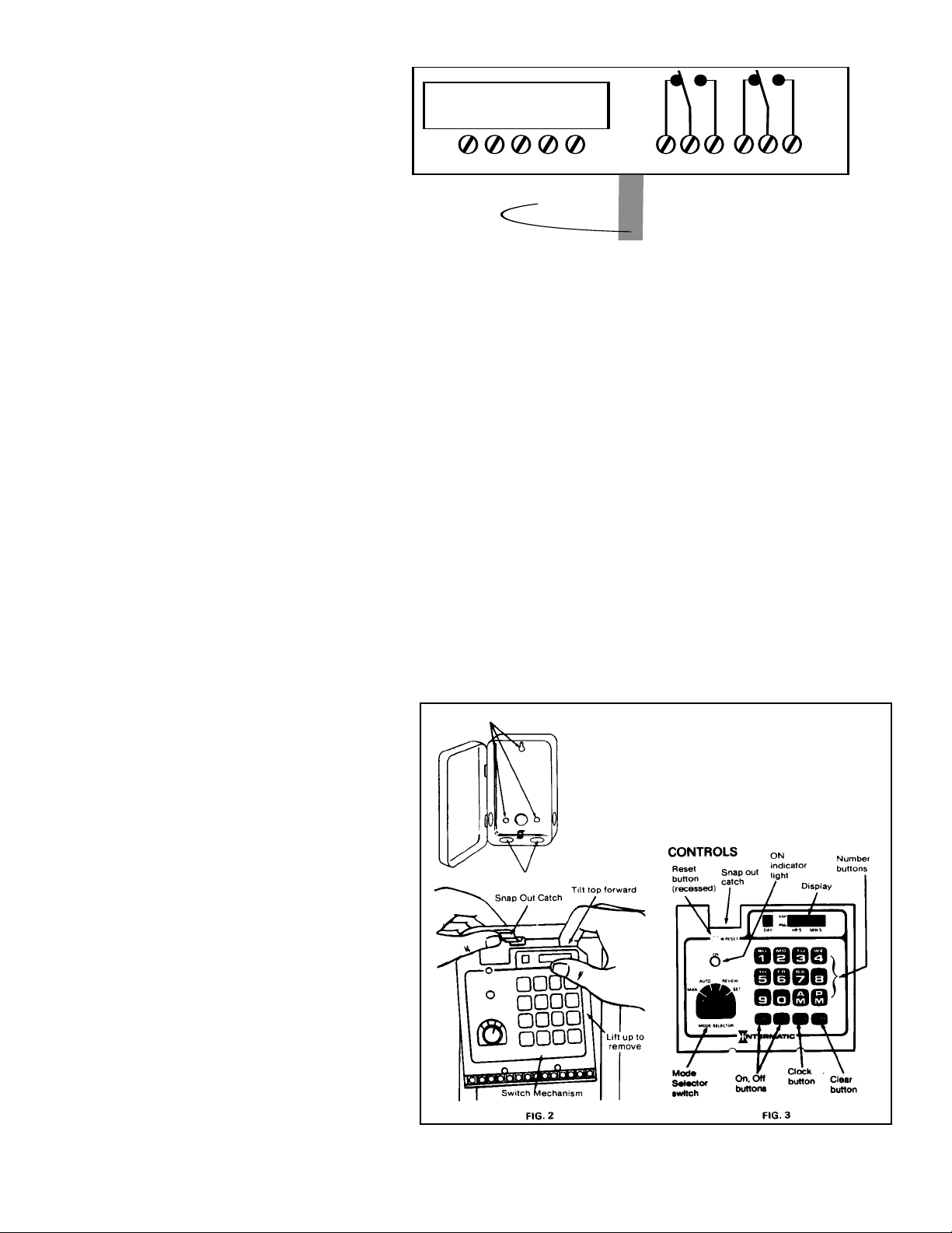
Installation
W
THE LOADS BEFORE INSTALLING THIS TIMER.
AND
1. Remove the mechanism from the case by depressing
the catch at the top of the case and pulling out. (See
Fig. 2) CAUTION: DO NOT TOUCH CIRCUIT BOARD
COMPONENTS.
2. Mount the timer in the desired location (three holes for
mounting are located on the back). (See FIg. 1).
3. Replace the mechanism in the case.
Lift left side of insulation off of retaining post and pivot
4.
it up and away to expose the terminal strip.
Strip supply and load wires by removing 1/2” of insula-
5.
tion.(Do not use aluminum wire.) Insert the wire ends
under the proper terminal plates and tighten the
screws firmly. (See Note Below)
6. Locate photo sensor timer input lead (large black cable
at bottom of terminal strip). Strip leads and connect
directly to photo cell or to connecting bell wire (14-18
AWG). Up to 1,000 feet of bell wire may be
used.
CAUTION: make all photo sensor connections
outside of the enclosure.
7. Replace the plastic insulator
8. Be sure that the battery clip is connected to the battery.
The batteries are factory installed.
9. Place the selector switch in the “MAN” position.
10. Re-apply power to the timer.
11. Wait until the display is lit steadily, then press “RESET” for two seconds. The display will now show: 1’10:00. The timer is now ready
for programming.
NOTE:
For inductive loads (lighting contactors, relays, etc.), it is necessary to install a surge suppressor across the time switch contacts. The
surge suppressor selected must be of the same voltage as the load (contactor or relay coil) being controlled. Use Intermatic part
number as follows:
176ET8A for 24 volt nominal loads - marked 8A
176ET9A for 120 volt nominal loads - marked 9A
176ET10A for 240 volt nominal loads - marked 10A
176ET22A for 277 volt nominal loads - marked 22A
Where excessive electrical noise is generated elsewhere in the load circuit an isolation relay may be required in addition to the surge suppressor or additional surge suppressors may be required on external contacts.
STEP 1. Insert load wire under one side of pressure plate and insert surge suppressor lead under other side of pressure plate.
STEP 2. Securely tighten the terminal screw.
Be certain that the body of the surge suppressor is at least 1/2 inch from the timer switch case. Insert surge suppressor(s) across each contact switching an inductive load. Do not use surge suppressors on both the normally open and normally closed side of the same output relay.
.
General Information (See Fig. 3)
MODE SELECTOR switch has four settings:
“MAN” -The automatic operation is bypassed while in
this position. Load(s) can be manually switched “ON”
or “OFF”.*
“AUTO”-Normal position for automatic operation.
Load(s) can be manually switched “ON” or “OFF”. The
timer will resume automatic operation beginning with
next set point.*
the
“SET”-T
“REVIEW”-To check the program, or clear entries for
program modification.
ON INDICATOR LIGHT:*
Flashes when the selector switch is set in “REVIEW”
or “SET”.
Glows steadily when normally “open” contacts are
“closed” during automatic or manual operation.
Does not glow when normally “open” contacts are
“open” during automatic or manual operation.
RESET BUTT
Resets the microprocessor before programming or to
erase the entire program.
CLEAR BUTTON:
Clears the displayed entry in “SET” or “REVIEW”.
CLOCK BUTTON:
Sets the time of day.
AND OFF BUTT
ON
To enter programming steps for “ON/OFF” set points as well as manually controlling the loads.
*NOTE: If the photo sensor has been connected the load will not switch ON unless darkness is sensed. To check the wiring, tempor-
arily disconnect the photo sensor from the time switch. This will allow the load to be switched ON, regardless of the ambient light
level, by pressing the ON keypad in either MAN or AUTO modes. A built in time delay may cause up to a 2 minute response delay to
sudden changes at Photo Sensor input.
o set or modify the clock, and program.
ON:
ONS:*
•ET716CK POWER AND LOAD CONNECTIONS
TIMER SCHEMATIC: Turn off power at fuse box or circuit breaker. Use
approved #18 to #14 gauge solid or stranded copper wire.
Mounting Holes
Knockouts
-2-
Page 3

Programming Steps
WARNING: DO NOT PRESS RESET BUTTON WHILE
PROGRAMMING OR THE ENTIRE PROGRAM WILL BE
.
LOST
SET OR MODIFY
Turn selector switch to “SET”.
1.
2. Press the numbered button corresponding to the day. For
examaple press ´2´ for Monday.
3. Enter the current time of day. For example, if the time is
8:00 AM press 800 and press “AM”.
4. For our example, the display will show: “2 ‘8:00”.
5. Press “CLOCK” button.
The display will now show: “- --:--.”
6.
To verify that the correct time is set, turn the selector
7.
switch to “AUT
steps 1-6.
8. Turn selector switch to “SET”.
PREPARE “ON” AND “OFF” SET POINTS FOR
PROGRAMMING.
1. List all desired ON and OFF set points as shown in the
example.
Example: The lighting load must switch ON when dark-
ness is sensed after 8:00 AM anytime from Monday thru
Saturday. The load must switch OFF at 11:00 PM
Monday thru Thursday and OFF at 2:00 AM on Friday
and Saturday (actually Saturday and Sunday morning).
DAY TIME AM/PM ON/OFF
2 (Mon) 8:00 AM ON
2 (Mon) 11:00 PM OFF
Since Tuesday thru Thursday repeat Monday the
COPY feature can be used. Refer to example 2 to follow.
6 (Fri) 8:00 AM ON
7 (Sat) 2:00 AM OFF
7 (Sat) 8:00 AM ON
1 (Sun) 2:00 AM OFF
Complete the above list for all on/off set points.
2. Now list all days to be repeated(exactly) from days
already programmed.
Example:Tuesday, Wednesday and Thursday repeat
Mondays schedule.
Day To Repeat ON Day Being Repeated
3 (Tue) ON 2 (Mon)
4 (Wed) ON 2 (Mon)
NOTES:
1. Any day can repeat any programmed day. A repeat day
2. If a day already has a program, it cannot repeat another
3. If a day being repeated has a program change, the day
ENTER THE PROGRAM
1. Enter the program in the exact order:
Press 2 800 AM ON
Displays 2 --:-- 2 -8:00 2 ´8:00 - --:-Press 2 1100 PM OFF
Displays 2 --:-- 2
Press 6 800 AM ON
Displays 6 --:-- 6 -8:00 6 ´8:00 - --:-Press 7 200
Displays 7 --:-- 7 -2:00 7 ´2:00 - --:-Press 7 800 AM ON
Displays 7 --:-- 7 -8:00 7 ´8:00 - --:-Press 1 200 AM OFF
Displays 1 --:-- 1 -2:00 1 ´2:00 - --:--
5 (Thu) ON 2 (Mon)
may not be repeated.
days cycle unless the scheduled events for that day
are removed.
repeating it will recognize that change
automatically.
Day; Time; AM/PM; ON/OFF
Example; for above listed on/off set pts.
THE TIME OF DAY:
O” or “MAN”. If the time is incorrect repeat
11:00 2 ,11:00 - --:--
-
AM OFF
AM is indicated as ˝ ´ ˝ flashing.
NOTE:
2. Enter the program for repeat cycles.
Example; for above listed repeat cycles:
Press 3 ON 2
Displays 3 --:-- 3 --:-- - --:--
Press 4 ON 2
Displays 4 --:-- 4 --:-- - --;--
Press 5 ON 2
Displays 5 --:-- 5 --:-- - --:--
3. The program is now complete. It is suggested that the
program be reviewed before activating the loads. Follow
the procedures shown in “REVIEW”.
REVIEW
1. Turn the selector switch to “REVIEW”.
2. Press the button corresponding to the day being
reviewed.
3. The display will show one of the following:
• Example: Press 3;3 -2:-- (Tuesday “3” repeats
Monday “2”)
or
• Example: Press 2;--:-- (Monday events can be reviewed). In the second example, each time the “ON”
button is pressed, the correct time for that operation
will appear. Likewise each time “OFF” is pressed, off
times will be displayed. Continue pressing ´ON´ and
´OFF´ until ˝- --:--˝ is displayed thus indicating all
possible setpoints have been reviewed.
To modify a set point, that set point must first appear on the
display. Next, the clear button is pressed. Display will then
show ˝- --:--˝ indicating that setpoint has been removed.
Turn the selector switch to “SET” and enter the new information in the correct order (day; time; AM/PM; ON/OFF).
COUNTING SET POINTS
Count each on and off set point. Our example would total 6.
Do not count repeat daily schedules. Up to 28 on or off set
points can be programmed. The display would show
“E EE:EE” if you tried to program the 29th set point.
OPERATION (Automatic)* (See Note* Bottom of Page 2)
1. Turn selector switch to “AUTO”.
2. Apply voltage to loads.
NOTE: When in automatic operation, if the “ON” or “OFF”
buttons are pressed, the loads will activate accordingly.
The load will stay in this condition until the next
programmed event.
BATTERY POWERED CARRYOVER
If the power goes out, the batteries will maintain the program and keep the correct time to within .01%, for a period
of 24 hours. In order to achieve 24 hours of carryover
batteries need to have been charged for at least 24 hours.
Battery recharging is automatic when the timer is in operation.
CAUTION: USE ONL
ABLE BATTERIES, AA SIZE, RATED 1.25 VOLTS. DO
USE
NOT
While under battery power, normally “open” loads will not
activate. The timer will recognize the set points and keep
the time of day. As batteries are depleted, the display will
dim and go out, but the program and time may still be maintained. Once power returns, if the display shows the correct
time, the time and program have been retained.
time of day
OF DAY.
+
OTHER
ANY
, refer to the section SET OR MODIFY THE TIME
+
+
flashing
flashing
flashing
NICKEL CADMIUM RECHARGE-
Y
.
Y
TYPE OF BA
When installing batteries
observe correct polarity.
+
TTER
CAUTION
o reset the
T
, the
PM is indicated as ˝ ‚ ˝ flashing.
-3-
Page 4

SYMPTOM
120 VOLT120 VOLT
11 22 33 44 55 99 1010 1111 1212 1313 1414
LOADLOAD
120 VOLT120
VOLT
CONTACTOR COILCONTACTOR COIL
TIMER POWERTIMER POWER
PHOTO SENSORPHOTO SENSORPHOTO SENSORPHOTO SENSOR
HOTHOT
NEUTRALNEUTRAL
NEUTRALNEUTRAL
HOTHOT
240 VOLT240 VOLT
11 22 33 44 55 99 1010 1111 1212 1313 1414
LOADLOAD
240 VOLT240
VOLT
CONTACTOR COILCONTACTOR COIL
TIMER POWERTIMER POWER
PHOTO SENSORPHOTO SENSOR
277 VOLT277 VOLT
11 22 33 44 55 99 1010 1111 1212 1313 1414
LOADLOAD
277 VOLT277
VOLT
CONTACTOR COILCONTACTOR COIL
TIMER POWERTIMER POWER
PHOTO SENSORPHOTO SENSOR
Load does not turn on or of
Note that the load will switch ON
Y WHEN A LOW AMBIENT
ONL
LEVEL IS SENSED by the
LIGHT
photo sensor. Also note the Photo
sensor has deliberate time delay
(up to 2 minutes.
Load turns on and off at the wrong
time. Note that the load will switch
ON ONLY WHEN A LOW AMBiENT
LEVEL IS SENSED by the
LIGHT
photo sensor
Display does not light up or shows
dim, erratic or meaningless data.
imer gains time on regular basis.
T
Timer loses time
imer set points or time of day are
T
altered sporadically
Timer loses program during power
outage
.
f.
.
POSSIBLE CAUSE(S)
1. Mode selector not in
2. Fault in wiring.
3. Load power is out.
1. Time and day of week on display read-out incorrect.
2. Program is in error.
1. Power supply deficient
1. Spikes on power line cause
extra counts.
1. Timer power out.
2. Timer faulty.
1. Electrical noise from timer
contacts.
2. Electrical noise on contacts
from other sources on controlled line.
1. Battery(s) defective.
2. Batteries not seated.
AUTO.
Trouble Shooting
Turn to AUTO or MAN. Press ON then OFF.
1.
2. If ON indicator light switches on and of
and wiring to load. Make sure supply voltage is provided to output relay common termi
nals (10 and/or 13) as shown in diagrams below
3. If ON indicator does not switch on and off power may be out. Check power supply
to timer and load. If power is on remove batteries. If light still does not operate,
return for servicing.
1. If wrong, set correct time. If correct, review set points (Switching times.) See*
2. Review set points. If set points are correct, return for servicing.
1. Check power supply. If power supply is OK, check batteries. Try removing batteries.
Discharged or faulty batteries may drain unit of power even with power on. Check
polarity and seating;. Let stand 10 minutes or more with the power on to charge
batteries. Reset timer
Turn to AUTO Or MAN. Press recessed RESET button with pen or pencil
10 a.m.
and hold for two seconds. While pressing: ON indicator light will be lit and display
will show a colon. When released, display should show 1˙10:00. If unit does not
clear properly try resetting with batteries removed and timer power on. Check
battery voltage, defective cells will measure less than .2 volt. If unit does not clear
, return for servicing. Make sure timer power connection are appropriate for
properly
supply voltage. See diagrams below
1. a. Change to quieter line.
b. Put in line filter or isolation transformer
c. Check for good grounds.
1. Correct fault.
2. Return for repair.
1a. Use surge suppressors.
Use isolation relay.
b.
2a. Use surge suppressors on contacts elsewhere.
b. Use RFI line Filter.
c. Use isolation relay.
1. Unclip battery connection from timer, check battery pack voltage. Pack should
measure approx. 5 volts or 1.25 volts per cell. Replace defective cell(s). It is best to
replacle all 4 cells.
2. Check for battery seating and connections.
CORRECTIVE ACTION
f, but load stays off, check connections
..
. RESET clears the stored program and sets the clock to Sun.
.
.
1. Wiring diagram example for
2. Wiring diagram example for
3. Wiring diagram example for
CAUTION: MAKE ALL CONNECTIONS TO PHOTO
1.
158ET861
120 volt installation.
240 volt installation.
277 volt installation.
SENSOR OUTSIDE OF ENCLOSURE.
DO NOT
APPLY
POWER TO PHOTO SENSOR CONNECTIONS.
2.
INTERMATIC INCORPORATED
1 MADE
SPRING GROVE, ILLINOIS 60081-9698
3.
4.
AND PRINTED IN U.S.A.
 Loading...