

Page 1

InterForm400
®
eForms & Intelligent Document Management
for i5, iSeries & AS/400
Page 2

2 User’s Manual for InterForm400
®
Page 3

Document IF-003-29
Users Guide for Intermate InterForm400
®
V2006.M01
Printed in Denmark 2006
No part of this guide may be photocopied or reproduced in any way, except where
noted, without the written consent of Intermate A/S.
All the names in this manual are fictional and any resemblance to existing people or
firms is purely coincidental.
© Copyright Intermate A/S 2004. All rights reserved.
AS/400, iSeries and i5 are registered trademarks of the IBM Corporation.
HP-PCL is a trademark of Hewlett Packard
All other trademarks mentioned in this document are registered trademarks of their
respective owners.
User’s Manual for InterForm400® 3
Page 4

Table of Contents
Table of Contents ...................................................... 4
About This Manual .............................................. 14
How the manual is organized ...................................... 14
What is new in the 2006 version ......................................... 17
What is new in this manual ........................................ 18
The modules of InterForm400 .......................................... 19
The Basic InterForm400 package .................................. 19
The InterForm400 Classic package ................................. 19
The ZPL Module ................................................ 19
The PDF and E-mailing Module .................................... 20
The PDF Security Module ......................................... 20
The InterWord400 Module ........................................ 20
The InterFax400 Module .......................................... 20
Getting Started ....................................................... 21
1. Preparation .................................................. 21
2. Installation ................................................... 21
3. Setting Up the System ......................................... 25
4. Work With Overlay/AFC Sample ................................. 29
5. About The Print Results ........................................ 31
Menu Structures and General Operation ................................. 33
1. Design Overlay ..................................................... 35
Selecting an existing overlay ...................................... 35
Creating a new overlay ........................................... 35
Copy Overlay from Another Overlay ................................. 36
Global settings of an overlay ...................................... 37
Duplex options ........................................... 39
Function keys for display of a spool file ........................ 40
Considerations for Zebra overlays .................................. 43
Extended Page Definition ......................................... 45
Copy Management .............................................. 46
Measuring Methods ............................................. 48
Orientation of design elements .............................. 48
The Design Screen .............................................. 49
Service Options ................................................. 50
Overlay Element Selection Filters .................................. 52
Page Control ............................................ 52
Copy Management ........................................ 53
Overlay elements ............................................... 54
1=FRAME ............................................... 54
2=HORIZONTAL LINE ..................................... 55
3=VERTICAL LINE ....................................... 56
4=LINE ................................................. 56
5=TEXT ................................................ 57
6=Print-info (Print information) .............................. 58
7=INK (fill pattern for succeeding sequence lines) ............... 59
Examples on use of Ink: ................................... 59
4 User’s Manual for InterForm400
®
Page 5

8=TABULATOR (Paragraph tabulation) ....................... 61
9=REMAP WINDOW (re-mapping text areas) .................. 63
I=IMAGE ................................................ 66
?=IF...THEN (conditional nesting of overlays) .................. 67
F=PCL-FILE ............................................. 70
G=HP/GL-2-FILE ......................................... 71
S=SUBOVERLAY ....................................... 72
* = COMMENT .......................................... 72
How the sequence lines in overlay design are executed ................. 74
Getting Familiar With Overlays .......................................... 76
Step 1. Making a Work Copy of the Overlay IF400DEMO ................ 77
Step 2. Make a Test Print of the Overlay+Spool Data ................... 79
Step 3. Entering the Design Window ................................ 81
Step 4. Printing the Overlay Definition List ............................ 82
Step 5. Adding Round Corners to the Address Field .................... 82
Step 6. Edit Subject Text ......................................... 84
Step 7. Formatting the body text ................................... 87
Step 8. Making Equal Distance Between Column Headers ............... 88
Step 9. Making Equal Distance between Item Line Columns ............. 90
Step 10. Defining the Column Headers White on Black ................. 92
Step 11. Defining the Item Line Bars ................................ 94
Step 12. Defining the 5 Item Coloumn Frames ........................ 95
Step 13. Defining the logo as a water mark ........................... 96
Step 14. Defining the Copy Management ............................ 98
Step 15. Defining the COPY Symbol as Watermark .................... 99
Step 16. Defining the Relatively Positioned Sub-form .................. 101
Step 17. Cleaning the Overlay for Remaining Text .................... 104
Step 18. The Result ............................................ 105
Example of Advanced use of Sub-overlays (Random text lines) ......... 107
Creating the Main overlay: ................................. 108
Creating the sub-overlay for formatting item groups ............. 109
Creating the sub-overlay for formatting the footer .............. 112
The result .............................................. 113
Main Menu Local Environment Setup ................................... 116
2. Test Print Overlay ............................................ 116
3. Merge Spool Entry with Overlay ................................. 117
8. Select File set ............................................... 119
9. Select Output Queue and Printer Type ........................... 120
10. Work with actual Output Queue ................................ 120
Working with Overlay Selectors ........................................ 122
Selection Criteria Entries ........................................ 123
Getting Familiar with Overlay Selectors ................................. 126
Step 1. Placing overlays in One File set ............................. 126
Step 2. Examining Spool Entry Selection Criteria ..................... 128
Step 3. Entering the Selection Criterias in the Selector ................. 129
Step 4. Testing the Selector ...................................... 131
General Description of Auto Forms Control Sub-system ................... 132
10. Start AUTO_FORM subsystem ................................ 133
11. End AUTO_FORM subsystem ................................. 133
User’s Manual for InterForm400® 5
Page 6

12. Work with Active Subsystem AUTO_FORM ...................... 133
Overview of AFC Main Definitions ...................................... 134
Auto Forms Control Definitions ........................................ 136
Entering queue and job names to an AFC definition ................... 136
Default Output Output Queue and Printer Type ................ 137
Template AFC-definition to be executed after this definition ...... 138
Additional parameters .................................... 138
AFC Definition Entries .......................................... 138
1=Merge with Overlay .................................... 140
2=Send Network Spooled File ............................. 143
3=Transform AFPDS to *USERASCII ....................... 144
4=Copy Spooled File ..................................... 145
5=Move Spooled File ..................................... 145
6=Hold Spooled File ..................................... 146
7=Delete Spooled File .................................... 146
8=Call Program ......................................... 146
9=Exit ................................................. 147
A=Change attributes ..................................... 147
B=Split spooled file ...................................... 148
C= Prepare for Finishing .................................. 148
D=Sort Spooled File ...................................... 149
F=Change Writer ........................................ 150
G=Archive to MultiArchive/400 ............................. 151
H=Archive in InfoStore/400 ................................ 151
P = Send PDF E-mail ..................................... 152
N = PDF File naming and -save ............................ 152
* = Comment ........................................... 152
Convert SAP spool entries (datatype *IBMSCS) ................ 152
SAP spool entries (datatype *IBMSCS2) ..................... 153
Generating multiple copies in input spool entries. .............. 153
Getting Familiar with Auto Forms Control ............................... 155
Example 1, Using Separate queues for Input and Output .............. 155
Step 1. Checking the Writer ................................ 155
Step 2. Checking if Auto Forms Control is running .............. 155
Step 3. Entering Auto Forms Definition AFC_INPUT1 ........... 156
Step 4. Defining move of print jobs with type *STD ............. 157
Step 5. Defining move of Print jobs with Formtype DEMO ........ 158
Step 6. Testing new functions in AFC_INPUT1 ................ 159
Example 2, Using same Queue for Input and Output .................. 160
Step 1. Checking the Writer ................................ 160
Step 2. Creating the AFC Definition: ......................... 161
Step 3. Restricting the writer to process type *STD jobs only ...... 162
Step 4. Preventing following AFC functions to process type *STD . 162
Step 5. Defining the Overlay Merge ......................... 163
Step 6. Cleaning up processed jobs ......................... 165
Step 7. Activating the AFC job AFC_INPUT1 .................. 166
Step 8. Testing the new AFC definition AFC_INPUT2 ........... 166
Using a “TEMPLATE” AFC defintion ............................... 167
2. Form Type Table ............................................. 170
The overlay selection entry field ............................ 170
6 User’s Manual for InterForm400
®
Page 7

Split Definitions ..................................................... 173
Split Definition Entries ........................................... 173
Calling a User Exit Program with the extracted spool pages ............. 175
Defining the spool file attributes for the result of a Split ................. 176
Example Using Split ............................................ 177
Finishing Definitions ................................................. 181
Defining Prinserter® Pre-process Definition. Fixed number of pages ...... 181
Defining Prinserter® pre-process Definition. Variable number of pages .... 183
Defining Print Order of Sorted Groups ....................... 183
Example 1, Non sorted ................................... 184
Example 2, Sorting in Ascending Weight ..................... 184
Example 3 , Sorting in Franking groups: ...................... 185
Defining PFE MailPrinter
®
Pre-process Definition ..................... 186
Defining Print Order of Sorted Groups ....................... 187
Example 1, Non sorted ................................... 188
Example 2, Sorting in Ascending Weight ..................... 188
Example 3 , Sorting in Franking groups: ...................... 189
Defining Stapling Pre-process Definitions ........................... 190
Defining Insertion Pre-process Definitions ........................... 192
How to distribute E-mails and faxes in InterForm400
®
: ................. 195
The E-mail/Fax Finishing Definition ................................ 195
1. How to find E-mail address / Fax number ................... 196
2. Key definitions ........................................ 197
3. Definition variables .................................... 198
4. Default PDF-file name .................................. 198
5. Definition E-mail text / Cover page text ..................... 198
6. Definition recipient-ID .................................. 199
7. E-mail addresses and fax numbers ........................ 201
8. Senders E-mail address ................................ 202
9. Encryption and Signature ............................... 203
10. PDF bookmark definition .............................. 204
8. Work with E-mail senders ............................... 205
The File Naming Finishing Definition ............................... 206
1. Receipient Key Definition .............................. 206
2. Variable Definitions .................................... 206
3. PDF File Name Composition ............................. 209
5. Page selections and Document breaks ..................... 209
6. Receipient ID Information ............................... 210
7. Closing User-Exit ..................................... 210
8. Encryption and Signature ............................... 211
9. PDF bookmark definition ................................ 211
Define Level Break Conditions for Finishing ......................... 212
Example 1, Level Break on Page Counter .................... 213
Find Recipient ID in the Following Positions ................... 214
Example 2, Level Break on Change in Customer Info: ........... 214
Example 3, Level Break on Customer ID and
Attention Person. ... 215
Using the Finishing Definition with Auto Forms Control ................. 216
Activate the Finishing pre-process definition ................... 216
Merge with pre-processed Finishing spool entry ................ 217
Distribute E-mails with Auto Forms Control ................... 218
The Reformat finishing definition ...................................... 221
Head ........................................................ 221
User’s Manual for InterForm400® 7
Page 8

User exit program ............................................. 223
Detail lines .................................................... 223
Totals ....................................................... 226
Footer ....................................................... 228
Insert reformatting in production ................................... 228
Sort Definitions ..................................................... 230
Page Selection criteria .................................... 232
Find sort fields in the following positions ...................... 232
Examples Using Sort ........................................... 233
Example 1. Sort by Type, “InterMate400" letters first: ........... 234
Example 2. Sort by Type, “MateSert/400” letters first: ........... 234
Example 3. Sort by Type and Customer ID: ................... 235
Example 4. Sort by Customer ID and type: .................... 235
PDF File Bookmarks ................................................. 238
Getting familiar with PDF Bookmarks ................................... 241
User Output Queue .................................................. 244
Example: Distribute Spooled Files depending on Spooled File Owner ..... 244
General Description of OSC (Output Schedule Control) .................... 246
10. Start OSCCTL subsystem .................................... 247
11. End OSCCTL subsystem ..................................... 247
12. Work with Active Subsystem OSCCTL .......................... 247
Describing the OSC definition lines ................................ 248
Principle of OSC (Output Schedule Control) ............................. 250
Getting Familiar with OSC (Output Schedule Control) ..................... 252
Specify input spooled file priority: ........................... 253
Specify placement of input spool file attributes at output: ......... 253
Define Sort Fields: ....................................... 254
Specify Grouping and separator page: ....................... 255
Define resulting output queues: ............................. 255
Specify automatic start scheduling: .......................... 256
Specify automatic start options: ............................. 256
Specify output queue for processed spooled files: .............. 257
Specify job priority: ....................................... 257
Working with Joint Reports ........................................... 258
1. Compose Joint Report ........................................ 258
Designing a Report Composition .................................. 259
1=Empty Overlay (front page) .............................. 260
2= Overlay with index .................................... 260
3=Overlay + spool entry ................................... 261
2. Test Print Report Overlays ..................................... 262
3. Test Print Report, 1 Page per Overlay ............................ 262
4. Print Report ................................................. 262
Administering InterForm400® Environment and Users ..................... 266
8 User’s Manual for InterForm400
1. Appoint Administrator ......................................... 267
2. Configure InterForm 400 ...................................... 268
4. Work with InterForm400® Users ................................. 272
®
Page 9

5. Work with file sets ............................................ 273
6. Connect Users with Overlay File Sets ............................ 274
Working with Fonts .................................................. 278
7. Work with Fonts ............................................. 279
1. Description of Additional Fonts .................................. 279
Example of Defining a Resident Printer font ................... 281
2. Work with soft fonts for PCL .................................... 283
File transfer HP SFP Font files from a PC ..................... 286
3. Auto download Soft Fonts ...................................... 287
5. Create barcode soft font ...................................... 289
7. Install True Type font for PDF .................................. 289
InterForm400
®
Predefined Soft Fonts .............................. 289
MICR Soft Font (Font ID 3998) ............................. 290
OCRA Soft Fonts ........................................ 290
OCRB Soft Font (Font ID 0003) ............................ 290
Barcode Support .................................................... 292
Barcodes in PDF output ................................... 292
Calculating barcode height ................................ 292
5. Create bar code soft font ...................................... 293
1. Code 39 ............................................. 293
Extended code 39 ....................................... 293
2. Code 128 and EAN128 ................................. 293
3. Interleaved 2 of 5 ...................................... 294
4. EAN8, EAN13 and UPC-A ............................... 294
Postnet Barcode ........................................ 294
Barcode PDF417 ........................................ 294
Datamatrix barcodes ..................................... 295
MICR E-13B ........................................... 295
Assigning Font ID’s to Barcode Softfonts ............................ 295
Example of editing a font ID for Code39 barcode ............... 296
Downloading a Barcode Soft Font ................................. 296
Getting Familiar with Soft-fonts and Barcodes ........................... 298
Step 1. Installing the Arial True Type Font ........................... 298
Step 2. Creating the Code128 Barcode ............................ 300
Step 3. Create font ID for the Arial soft-font ......................... 301
Step 4. Define auto-download of fonts (Arial and OCRB) ............... 301
Step 5. Testing the Barcodes in an Overlay ......................... 305
Work with Zebra fonts ................................................ 308
11. Description of Zebra fonts .................................... 308
CG Triumvirate .......................................... 309
Dot matrix .............................................. 310
Defining barcodes for Zebra printers ......................... 310
Using soft fonts for printing on Zebra ........................ 312
12. Work with ZEBRA soft fonts ................................... 313
13. Work with fonts in ZEBRA flash memory ......................... 314
Download a soft font into flash memory ...................... 314
Delete a soft font from flash memory ........................ 315
14. Substitution ZEBRA internal fonts .............................. 315
19. Initiate ZEBRA flash memory and reload fonts and images .......... 316
User’s Manual for InterForm400® 9
Page 10

8. Work with images ................................................. 319
Working with black and white images .............................. 320
Importing black and white images. .......................... 320
Working with color images ....................................... 321
Import color images ..................................... 322
Work with Zebra images .............................................. 323
11. Work with ZEBRA images .................................... 323
12. Work with images in ZEBRA flash memory ....................... 324
19. Initiate ZEBRA flash memory and reload fonts and images .......... 324
9. Work with PCL Files ............................................... 325
Import PCL file ................................................ 327
10. Work with palette ................................................. 329
Change the definition of the colors. ................................ 329
11. Work with paper control options .................................... 331
1. Paper type to PCL-drawer conversion ............................ 331
2. Output Sorter Bin Support ..................................... 332
Defining an Output Sorter Bin for a User ...................... 332
20. Import Certificates ............................................... 336
Service Functions ................................................... 337
1. Create Demo Spool Entry ...................................... 337
5. Display All Displayable Characters .............................. 338
6. Save spooled file to the folder APF3812 .......................... 338
7. Print Saved Spooled File from the folder APF3812 .................. 339
8. Print Resource X-reference .................................... 339
9. Work with Journaling ........................................ 340
21. Export of InterForm400 resources .............................. 341
Copy resources to export library. ............................ 341
Work with resources in export library ........................ 342
Work with distribution .................................... 342
22. Import of InterForm400 Resources ............................. 343
Work with resources in import library ........................ 343
Transfer resources to the production library ................... 344
40. Install/upgrade InterWord 400 ................................. 346
50. Apply PTF from folder APF3812 ............................... 346
60. Install Swiftview at drive C: .................................... 347
70. Install InterForm Designer on your PC ........................... 347
80. Prepare server to support InterForm Designer .................... 347
How to create PDF files .............................................. 349
Resources that can be used for PDF output ................... 353
Fonts used in PDF output ................................. 353
IFS directories used by MRGSPLFPDF ...................... 353
Appendix A - Installation ............................................. 356
System Requirements .......................................... 356
First Time Installation ........................................... 356
License Codes ................................................ 356
Release Update ............................................... 357
10 User’s Manual for InterForm400
Upgrade remote sites .................................... 362
®
Page 11

Relations to Other Applications ................................... 362
Performance .................................................. 363
Printing ................................................ 363
Processing ............................................. 363
Appendix B - Attaching Printers to the iSeries ............................ 365
Attachment Methods ............................................ 365
Attaching through a Twinax Protocol Converter ................ 365
System Configuration by Auto Configuration .................. 365
Configuring a Printer Device Manually ....................... 366
Changing Device Description from 5219 to 3812 ............... 367
Attaching through a TCP/IP Raw Socket (Port 9100/3700) .............. 368
Attaching through a 5250 Terminal ................................ 368
Enabling Host Print Transform on an existing Printer Device Description
............................................... 369
Attaching through a PC Printer Port ................................ 369
Client Access/400 for Windows 95/NT ....................... 369
Attaching through a TCP/IP LPD Printer Server (Remote Writer) ......... 370
Creating or Changing an Output Queue for TCP/IP LPD Printing .. 370
Attaching through a TN5250E Print Client ........................... 371
Testing the Connection .......................................... 372
Trouble Shooting ........................................ 372
Appendix C - Printer Types ............................................ 374
Black and white printer types ............................... 374
Color printer types ....................................... 375
Zebra printer types ....................................... 375
Cassette Mapping (Drawers) ..................................... 376
Selecting drawer by drawer number ......................... 376
Select Drawer using Paper Type ............................ 376
Appendix D - Interfaces (Protocol Converters) ........................... 378
Appendix E - Codepage Support ....................................... 380
Appendix F - Font-ID Information ....................................... 382
IBM 3812 font-ID Information ..................................... 382
IBM Compatible Font List ........................................ 383
Shipped Zebra Fonts ........................................... 385
Typefaces known by PCL-Printers ................................. 386
Appendix G - Limitations of the Light Version ............................ 388
Appendix H - Commands in Spooled Files ............................... 390
Example of using Escape Commands in the Data Stream .............. 397
Appendix I - InterForm400
®
CL Commands .............................. 400
NetServer Commands .......................................... 400
The Add Netserver File Share Command ..................... 400
The Add NetServer Printer share Command .................. 400
The Change Netserver Attributes Command .................. 400
The Display Netserver Attributes Command ................... 400
The End Netserver Command .............................. 401
The Remove NetServer share Command ..................... 401
The Start Netserver Command ............................. 401
User’s Manual for InterForm400® 11
Page 12

Save/Restore and Export/Import Commands ........................ 401
The Export Chart Command ............................... 401
The Import Chart Command ............................... 402
The Restore Library from Folder Command ................... 402
The Save Library to Folder Command ....................... 402
Joint Report Commands ......................................... 403
The Clear Link to Joint Report Command ..................... 403
The Link Joint Report Command ............................ 403
The Print Joint Report Command ........................... 404
AFC and OSC Commands ....................................... 404
The End Auto Forms Control Job Command .................. 404
The Start Auto Forms Control Job Command .................. 405
The Start OSC Job Command .............................. 405
Utilities relevant for AFC Exit programs ............................. 405
The Transform *AFPDS print Command ...................... 405
The APF3812 Overlay Merge Command ..................... 405
The Copy CPI Spooled File Command ....................... 406
The Page Builder Spooled File Command .................... 406
The Convert PCL Spooled File Command .................... 409
The Merge Spooled File PDF Command ..................... 410
The Merge Spooled File ZPL Command ...................... 410
The Print ASCII File Command ............................. 411
The Split Spooled File Command ........................... 411
Spooled File Inspector (SFI) ............................... 411
The Zip Stream File(s) Command ........................... 412
Other Utility Commands ......................................... 413
The Edit Print Command .................................. 413
The APF Work Output Queue Command ..................... 414
The Display Black/White image Command .................... 415
Encrypt InterForm400 PDF File ............................. 416
The HP Macro Command ................................. 416
The Import InterForm400 Resources Command ............... 418
The PCL-file from folder to Member Command ................ 418
The Print PCL-member Command .......................... 419
The Print TIFF File Command ............................. 419
The Print X-Ref List Command ............................. 420
The Send Mail Commnd .................................. 420
The Work Mail addresses Command ........................ 420
The Work with Profile Jobs Command ....................... 420
Work with Stream File Locks ............................... 421
The TIF-file from folder to member Command ................. 422
Appendix J - Merging overlays with OV/400 and InterWord400TM print jobs ... 424
Appendix K - Forms Server for non-AS/400 environments .................. 426
Adding Overlays to *SCS PC Print Jobs (PC Mail Merge) ............... 426
Adding overlays to *ASCII PC printjobs (PCL) ........................ 427
Appendix L - PDF and PCL Viewing ..................................... 430
Appendix M - InterForm400 charts ..................................... 435
The Work with Charts command, WRKCHT ......................... 436
12 User’s Manual for InterForm400
PDF viewing: ........................................... 430
PCL viewing: ........................................... 430
®
Page 13

The &&CHA Chart commands .................................... 446
Appendix N - Sending E-mails from the AS/400 ........................... 459
Setup of SMTP ................................................ 459
Combining SMTP and Domino/400 on the same machine .............. 460
Appendix O - Graphical Designer: Install and use ......................... 461
Requirements for the Graphical Designer ........................... 461
Requirements for the iSeries (AS/400): ....................... 461
Requirements for the PC: ................................. 461
Requirements for the network: ............................. 461
Limitations of the Graphical Designer .............................. 462
Installing the Graphical Designer .................................. 462
Installing JAVA Environment ............................... 462
Installing and setting up the InterForm400
®
Graphical Designer ... 462
Starting the Graphical Designer ................................... 463
Start designing an overlay ....................................... 463
Create a new overlay ..................................... 464
Edit an existing overlay ................................... 464
Open a Spooled File ..................................... 464
Settings and tools for the design .................................. 465
Changing the displayed size ............................... 465
Previewing the result in Acrobat reader or SwiftView ............ 465
Other Design preferences ................................. 465
Designing the overlay ........................................... 467
The spool view .......................................... 469
The Result view ......................................... 470
Inserting design elements ................................. 472
Local save in the designer ................................. 474
Movement of elements in the result view ..................... 474
Grouping and ungrouping elements ......................... 475
Appendix P - Import/Export extension .................................. 477
Multiple Export Libraries (MEL) feature ............................. 477
Description ............................................. 477
Activation/deactivation .................................... 477
Usage ................................................. 477
The Import InterForm Ressources (IMPAPFRSC) command ............ 477
Restrictions: ............................................ 478
Parameters: ............................................ 478
Examples .............................................. 478
Escape messages: ...................................... 479
Sample scenario of using MEL and the IMPAPFRSC command ......... 479
Appendix Q: The PDF Security module .................................. 480
Requirements for the PDF security module .......................... 480
Technical details ............................................... 481
20. Import Certificates .......................................... 481
Recommendations related to JAVA Performance .................... 483
OS/400 System values .......................................... 484
OS/400 Subsystem settings ...................................... 484
Index .............................................................. 486
User’s Manual for InterForm400® 13
Page 14

About This Manual
This manual is intended for the person or people responsible for production printing on
the site. For instance the system administrator.
InterForm400® is designed to operate completely transparent to the user, which means
this manual is only used for designing overlays, setting up printers and for configuration
of sub-system handling the overlays and printers.
InterForm400® requires no programming of any kind in order to operate with existing
print jobs. All logical definitions for searching and selecting print jobs are set up in the
InterForm400® menus.
The manual describes functions, that may require the purchase of additional modules.
Whenever additional module(s) are required it should be mentioned, but that cannot be
guaranteed. For guidelines refer to page 19. Ask your local InterForm400 reseller if in
doubt.
The terms ‘AS/400', ‘iSeries’ and ‘i5' may be used in the manual. Unless mentioned they
refer to all 3 types of machines.
How the manual is organized
This manual is built as a technical reference as well as a self study on creating overlays
fast and easy. The self study sections are constructed as follows:
Getting Started: Work through this chapter if you are installing the system for the
first time. You will end up with an illustrative sample printed
through the AutoFormsControl sub-system.
Getting Familiar
with Overlays: This section will use the demo overlay as template and lead you
through virtually all the design features in InterForm400®. To
gain full benefit of this section you should have worked through
the section Getting Started.
Getting Familiar with
Overlay Selectors The overlay selector is a vital element of InterForm400®. It
enables specific pages in a spool entry to have unique overlays
attached according to the contents of the spool data. To gain full
benefit of this section you should have worked through the
section Getting Familiar with Overlays.
Getting Familiar with
Auto Forms Control This chapter will lead you through a real life example of using
Auto Forms Control. You will be guided step-by-step through the
entire procedure. To gain full benefit of this section you should
have worked through the section Getting Started.
Getting Familiar with Softfonts and Barcodes: This section is structured as a learning-by-doing example which
Throughout the manual you will find the following symbols, which will provide you with
special information:
J TIP J
If you would like to make an easy thing, then just make a ...
14 User’s Manual for InterForm400
makes extensive use of download fonts and bar codes.
®
Page 15

L TROUBLE SHOOTING L
Did you remember to ...
M WARNING M
Do not do that, as you will end up in deep..
G NOTE G
Important information
User’s Manual for InterForm400® 15
Page 16

16 User’s Manual for InterForm400
®
Page 17

What is new in the 2006 version
This Users Guide describes functions available in version 2006M01 and newer.
Below are listed most of the new features added in InterForm400 since the last Users
Guide (version 3-28) intended for InterForm400 version 2004M01.
• Bookmarks and links can now be added to output PDF files via a command in
the *SCS spooled file. Refer to page 396 for more details of the &&BMK and
&&URI commands.
• Grey TIF images are now supported in InterForm400. Until now only sharp
black/white images have been supported. LZW compressed files are also
supported. This will greatly improve the quality of the output images and ease
the installation in InterForm400. Refer to page 321 for more information.
• Support for the DBCS flag on spooled files has been added. InterForm400 does
not support DBCS, but with the 2006 versions spooled files with IGCDTA(*YES)
are now also supported for merge in InterForm400.
• PDF output for InterWord400 spooled files can now be generated. (.IMG
commands in the RTF files are not yet supported.)
• Soft fonts based on True Type Fonts installed for PDF output can now be
restricted only to be included for some PDF files. This can be used for reducing
the size of the PDF files for PCs, that already have this TTF installed. Refer to
page 288 for details.
• OS400 V4R4M0 is the minimum release on which InterForm400 can be
installed, but notice that the graphical designer requires V4R5M0 and that some
parts requires V5R1M0 (e.g. the ZIP command, the PDF Security module and
the InterFax module). The 2007 versions of InterForm400 are planed to support
V5R1M0 as minimum release.
• The E-mail finishing definition have been extended:
Up to 9 variables can be defined,
You can present the e-mail text in arial
You can include HTML commands in the e-mail text
You can send each part of the spooled file to 2 receivers (include a CC).
You can use e-mails found in the spooled file more easily.
Two new demo sources for exit programs have been included.
Refer to page 195 for an updated description of the e-mail finishing definition.
• The user exit closing program for the PDF file naming finishing definition can
now receive up to 20 parameters. A new demo source is included. Refer to page
210 for details.
• The datamatrix barcode is now supported for ZPL output. For PCL and PDF
output this barcode is not supported yet.
• A new version of Swiftview is included in InterForm400. Please reinstall
Swiftview on the PCs to get this update.
• The graphical designer is now able to change the font for many lines at a time.
Refer to page 475 for more information.
• If overprinting have been used in the original *SCS spooled file to print in bold,
this bold will now also be printed as bold if you print out the PDF file resulting
from a merge in InterForm400.
User’s Manual for InterForm400® 17
Page 18

• Additional copies of each page can now be printed by inserting the command
&&CPY in the *SCS spooled file that you merge. Refer to page 396 for more
information.
• Stapling is now supported for additional printers. Stapling for additional Minolta,
Ricoh and Lexmark printer models have been added. Selection of the printer
model have been restructured to make it easier to find the right printer model.
Refer to page 47 and 190 for more information about stapling in InterForm400.
What is new in this manual
This lists the major changes to the manual, that does not concern the new functions. The
changes/additions are:
• An alternative way to install the graphical designer has been included.
Installing via the installation files found in the IFS is described. Refer to page
462 for information.
• It is made clear, that remapping spooled file text out of the paper will not
remove the possibility to find the text in the resulting PDF files. Unadjusted
tabulators will fully remove the text.
• Additional (and hidden) function keys on the license screen are now
documented in the user manual - refer to page 356 for more information.
• Even tough it was claimed for the 2004 versions the limitation of 300 remap
window lines have not been removed. This limit is however very high, so it
should not be a problem for anyone. Overlays using many remap window lines
can be made smaller and more efficient and are easier to maintain by using
IF..then lines instead. Ask your local InterForm400 contact for more information
if needed.
• A link to IBM helping you to setup SMTP in combination with Domino have been
added. The link can be found on page 460.
18 User’s Manual for InterForm400
®
Page 19

The modules of InterForm400
From the 2004 versions of InterForm400 a number of modules are offered for
InterForm400. Below basic InterForm400 package and the modules are described.
As minimum you need to buy either the InterForm400 Light version or the basic
InterForm400 package.
If wanted you need to install the additional modules InterWord400 and InterFax400.
InterFax400 is installed via option 80 on the InterForm400 Service menu and requires
the InterForm400 CD. The other modules are installed along with InterForm400 and only
need to be enabled with a new license code.
Refer to Appendix G on page 388 for details of the light version.
The Basic InterForm400 package
The basic InterForm400 does not contain any of the functions, that are available as a
module. That means, that the following is NOT
• ZPL output
• PDF output and E-mailing with attached PDF files
• Possibility to encrypt and digitally sign PDF files created by InterForm400
• InterWord400 (OV400 replacement and AS400 mail merge)
• Possibility to fax (Interfax).
• Swiftview licenses apart from 1 license, that is delivered with InterForm400 for
free
• And any other module, that may be offered for InterForm400.
included in the basic package:
However the number of output queues supported for PCL output in the basic package is
unlimited.
The InterForm400 Classic package
The InterForm400 Classic package fits the functionality of the previous versions of
InterForm400. The Classic package includes PCL output on an unlimited number of
output queues, ZPL output, PDF output and e-mailing.
If you already have purchased the full InterForm400 license prior to the 2004 versions
(and have maintenance) then you will get a 2004 license code for the classic package. If
you already have bought InterWord400 or additional SwiftView licenses then the 2004
code will of course also include that.
The ZPL Module
Purchase this module and you will be able to print on ZPL compatible printers.
In order to start working with Zebra output you need to create a Zebra File set.
Refer to page 273 for how to do that. This module is included in the classic package.
User’s Manual for InterForm400® 19
Page 20

The PDF and E-mailing Module
If you want to create PDF files in InterForm400 and/or send E-mails with attached PDF
files you need this module. This module is included in the classic package.
The PDF Security Module
If you want to encrypt PDF files created by InterForm400 and/or digitally sign them, then
you need this module. Note, that you also need to buy the PDF and E-mailing module if
you do not have the classic package. Refer to Appendix Q on page 480 for more
information.
The InterWord400 Module
Can be used as a substitute for OfficeVision400. It converts OV/400 documents into RTF
format. Offers also the possibility to do mail merge directly on the iSeries. Ask your local
InterForm400 reseller for more details.
The InterFax400 Module
The InterFax400 module enables distribution of the InterForm400 documents via
facsimile. The InterFax400 modules ensures a correct translation of the InterForm400
documents. This is done in combination with the E-mail/Fax finishing definition in
InterForm400. Note that InterFax400 is only supported for V5R1 or newer.
20 User’s Manual for InterForm400
®
Page 21

Getting Started
The idea of the following procedure is to give you a safe and easy start on the
InterForm400
OS/400 knowledge is needed.
The final result of the following will print a sample spool entry with a predefined overlay
by means of the Auto Forms Control (AFC) system, which is an essential part of the
InterForm400
1. Preparation
• Make sure your OS/400 level is at least Version 4 release 4 or newer. (Refer to
• Make sure you have QSECOFR rights on the AS/400, or similar with USER
• Make sure you have a PCL4 or PCL5 compatible printer attached either through
®
system. No knowledge on InterForm400® is required, and only minor
®
system. The result will be printed on a PCL printer of your own choice.
System Requirements page 356)
CLASS *SECOFR authority. The user profile used for the install must at least
have *ALLOBJ, *SECADM and *SPLCTL authorities and must be in the system
directory (WRKDIRE).
Twinax (direct or through a Terminal or a PC emulator card) or a LAN (SNA
APPC, TCP/IP LPD, Raw Socket (port 9100) or TN5250E). Any PCL5 Printer
configured to use IBM Host Print Transform can be used. Refer to Appendix B
page 365 for detailed information on attaching printers.
2. Installation
Now you are ready to install the InterForm400® system from a CD-ROM.
Note: Refer to page 357 if you are performing the below steps as an upgrade to an
existing InterForm400
1. Insert the CD into the CD-ROM drive of your AS/400.
2. Enter the following CL command on a command line to install:
3. You are now prompted to choose your preferred language for the installation:
Note that Laser printers with IPDS as the only language can not be used.
®
installation.
LODRUN DEV(Device)
Where Device is the name of the Device containing the media. (If you are using
the systems default CD-ROM drive you can use *OPT instead of the Deviceparameter.)
Note: If the installation detects an existing version of InterForm400
®
on your
system you will, at this point, get prompted to selected installation
method. Refer to page 357 for more information on release updates.
User’s Manual for InterForm400® 21
Page 22

InterForm 400 version 2004.M01 INTER03
DE: Wählen Sie bitte eine Sprache aus, während verwendet zu werden installieren
Eingabetaste --> Weiter
DK: Vælg sprog for instruktioner under denne installation.
Tryk på Enter for at fortsætte.
ES: Seleccione por favor un lenguaje para ser utilizado durante instalan.
Pulse Intro para continuar.
FR: Veuillez choisir la langue à utiliser pendant l'installation.
Appuyez sur ENTREE pour continuer.
GB: Please select a language to be used during install.
Press Enter to continue.
PT: Favor selecionar uma língua a ser usada durante a instalação.
Aperte Enter para continuar.
GB DE=Deutsch, DK=Dansk, ES=Españoles, FR=Français, GB=English, PT=Português
F3=Exit F12=Cancel
4. Confirm on the next screen (with Enter), that you are installing InterForm400.
The screen after that requires you to enter a valid licence type, in order to allow
the installation to proceed. You can also leave it blank and fill it out later.
INS0125 InterForm 400 version 2004.M00 INTER03
Type license information, press Enter.
InterForm 400 license code ____ ____ ____ ____ ____ ____ ____ ____ ____
Notice:
License type and code must match.
InterForm 400 cannot be used before a valid license code is entered.
F3=Exit F12=Cancel
5. In the following screen you can set the preferred language used in
InterForm400. The language can be changed later if needed. This is done by
option 2 at the Administration menu to change the global settings for
InterForm400® or use option 4 to select language for specific InterForm400
users.
Note: InterForm400® CL commands like MRGSPLFPDF, APF3812 etc. will be
22 User’s Manual for InterForm400
®
installed in the language chosen here, and can not be changed unless a
re-installation is made.
®
Page 23

INS0121 InterForm 400 version 2004.M01 INTER01
Select primary language, press Enter.
Primary language . . . . . . . GB DE=Deutsch, DK=Dansk, ES=Españoles,
FR=Français, GB=English, PT=Português
Primary language is used for:
1. The language of commands.
2. The language of displays.
3. The language of the manual.
Notice:
Language of commands can only be selected during install.
Primary language can be changed at the administration menu option 2.
F3=Exit F12=Cancel
6. If this is the first time InterForm400® is installed on your system, you should
leave the default values. Refer to page 340 for more information on journaling.
INS0122 InterForm 400 version 2004.M01 INTER01
Select journal, press Enter.
Journal . . . . . . . . . . . APFJRN___
Library . . . . . . . . . . APF3812___
If a journal is selected, changes are recorded to a journal receiver.
It is recommend to use the journal APFJRN in library APF3812.
This journal will be created during install, if used.
If you select a journal in a other library this journal must already exist.
F3=Exit
7. The installation guide now gives you an overview of parameters you have
chosen, for the installation of InterForm400
®
. Press F10 to start installation. Note
that Status messages will be shown at the bottom of the screen during
installation.
User’s Manual for InterForm400® 23
Page 24

INS0129 InterForm 400 version 2004.M01 INTER03
Start installation with selected options.
Device . . . . . . . . . . . : OPT01
Category . . . . . . . . . : *OPT
CISC/RISC . . . . . . . . . : *RISC
License type . . . . . . . . : *Demo
Licensed modules . . . . . . : *Classic, *PDF-Security, *InterWord
Primary language . . . . . . . GB
Journal . . . . . . . . . . . APFJRN
Library . . . . . . . . . . APF3812
Press F10 to install.
F3=Exit F10=Start installation F12=Cancel
8. Press F10 to complete the installation.
24 User’s Manual for InterForm400
®
Page 25

3. Setting Up the System
The system is now ready for setting up administrators, file-sets, print queues and
printers.
Enter the InterForm400
APF3812/APFMENU
When entering InterForm400
administrator. Enter option 80. Administration Menu and go through the menu points 1
- 6, as follows:
1. Enter 1. Appoint Administrator to appoint an administrator of InterForm400
(e.g. QSECOFR). It is recommend to allow access to ALL until the system enters
production.
2. Enter 2. Configure InterForm 400.
3. Type in a default output queue. Select printer type according to the supported
HP PCL emulation of your printer. (It is recommended to select HP4 or HP4D (D
for duplex) in order to have support for all fonts used in the overlay sample).
Refer to page 374 for other values.
Always select ASCII850 as interface type.
(see list of Interface types page 378 in the user guide)
Enter Y/N (Yes/No) whether you want to "Allow Users to override default
printer type". Answer ‘Y’ if in doubt.
®
menus:
®
for the first time, you will be asked to appoint an
®
,
Configure InterForm 400 APF101D
1/7
Specify default output queue for users with no individual output queue.
Users may override value when using the system.
Output queue . . . . PRT01
Library . . . . . QUSRSYS
Specify default printer type
Printer type . . . HP4 (IBM4019 IBM4029 IBM4039 HPII HPIID HPIIP
HPIII HPIIID HPIIIP HP4 HP4D HP4_PJL
HP4D_PJL HP5C HP4500 HP4500D
ZEBRA203 ZEBRA300)
Interface ASCII850 (SYSTEM SYSTEM850 SYSTEM852 ASCIIR8
ASCII850 ASCII852 WORKSTN WS31N
WS347N WS348NIDA3X IDA5219 IDA812N)
Allow users to override default printer type ? Y (Y N)
F3=Exit F12=Cancel
When you press Enter you are presented with the screen below. Here you decide what
form type to use as default (use *STD if in doubt), the paper size, and whether or not the
InterForm400 users are allowed to override the paper size on overlays (See more on
page 38).
User’s Manual for InterForm400® 25
Page 26

Configure InterForm 400 APF101D
2/7
Specify default form type for the InterForm 400 system.
Users may override value when using the system.
Form type *STD______
Select paper size 4 1 = LETTER 5 = COM-10 A = LEDGER
2 = LEGAL 6 = MONARCH B = A3
3 = EXECUTIVE 7 = C5 C = A5
4 = A4 8 = DL
Do you want to define paper size on the individual overlays Y (Y N)
F3=Exit F12=Cancel
Leave the macro offset value at “0". Refer to page 269 for additional info
Configure InterForm 400 APF101D
3/7
Number to be added to the macro numbers the system works with . . . ___0
The reason to add a number can be, that printers are equipped with
flash-simm cards, that does not correspond to the HP standard saying,
that a macro in the printers internal memory should be selected,
even if it has the same number as a macro in the flash-simm.
F3=Exit F12=Cancel
If you do not intend to exchange overlays between a number of InterForm400
®
installations, you can answer N to using DDM. Refer to page 270 for more
information on using DDM.
Configure InterForm 400 APF101D
4/7
Do you want to use DDM to InterForm files
on other AS/400
Use DDM . . . . . . . Y (Y N)
F3=Exit F12=Cancel
Enter the Network name/NetServer Name of the AS/400 you work on. This
name can be found with the command APF3812/DSPNETSVRA, or can be
found under "other computers" on your Client Access connected Windows PC.
This option is used in relation to the PCL viewer and the DDM features. If you
26 User’s Manual for InterForm400
®
Page 27
are in doubt you can also specify the IP address of the AS/400 - without
surrounding ‘’.
Sharename can be used for situations, where you do not want to share the
complete QDLS (In InterForm400 it used mainly for the possibility of a graphical
view). If you instead have shared either the APF3812 folder or the
APF3812/VIEW folder you can state the sharename here. Note, that you need to
add the share before InterForm400 will accept this sharename. Use e.g. the
command: APF3812/ADDFILSHR to share a folder.
Public authorisation: When you view a merge graphically a temporary file is
created in APF3812/VIEW. You can restrict access to this file, so that the public
authority is *EXCLUDE. Then only the file creator and users profiles with
authority *ALLOBJ have access to the file.
G NOTE G
The change of PUBLIC authority of the files in QDLS/APF3812/VIEW is only used
when creating new files (not when replacing existing). To use the new authorisation
delete the files in QDLS/APF3812/VIEW, that holds the names of your end users. Do not
delete the file SVIEW.EXE.
Configure InterForm 400 APF101D
5/7
The Name that is used for this AS/400
under "Other computers" on PC's.
Networkname . . . . . QS4449079__
Sharename. . . . . . . VIEW______
Public authorisation to files that are created in the APF3812/VIEW folder.
0 0=*EXCLUDE
1=*ALL
F3=Exit F12=Cancel
The selection of Primary language for operating InterForm400® was chosen
during the installation of InterForm400
Configure InterForm 400 APF101D
6/7
Select primary language for:
1. The language of displays.
2. The language of the manual.
Language code . . . . GB
DE=Deutsch, DK=Dansk, ES=Españoles, FR=Français, GB=English
F3=Exit F12=Cancel
®
. It can be altered here if needed.
If you want Auto Forms Control to monitor output queues with printers attached,
you now have the option to state which form type to print from the shared output
queues. State N for not using the program, APF3812/STRWTRCHK program if
in doubt.
User’s Manual for InterForm400® 27
Page 28

Configure InterForm 400 APF101D
7/7
Do you want to use the APF3812/STRWTRCHK program as validity checking program
for the STRPRTWTR and STRRMTWTR commands, to avoid a writer to be started with
FORMTYPE(*ALL) on one of the output queues defined in Auto-Forms-Control, and
if yes, what formtype has to replace *ALL when a writer is started on one of
these output queues.
Use APF3812/STRWTRCHK as a validity checker N (Y N)
Formtype to replace *ALL . . . . . . . . . . __________
This option is especially usefull, if you are using the same output queue
for both input to AFC-functions and for output to a printer, as a writer
never should be started with FORMTYPE(*ALL) on souch an output queue.
F3=Exit F12=Cancel
4. Enter 4. Work with InterForm400 users. Press F6 to enter your AS/400 user
ID. Later you can add additional users which will have access to configure
and/or define overlays and merge-definitions in InterForm400®.
5. Enter 5. Work with file sets. Press F6 to create an overlay file set called e.g.
TEST (select 1=Black/White Laser for Printer Class). This file set is referred in
the Getting Familiar with Overlays section on page 76. Later you can add file
sets for different purposes or for specific users.
6. Enter 6. Connect users with overlay file sets. Connect your user profile to file
set SAMPLE and the file set you created in the previous step.
7. Start subsystem AUTO_FORM: From the Select 5. Work with Auto Forms
Control from the InterForm400 Main Menu followed by option 10. Start
AUTO_FORM subsystem.
You can now proceed to install and setup the PCL/PDF-viewer (please refer to page 430
for further information) and the graphical designer (refer to page 461 for more
information).
28 User’s Manual for InterForm400
®
Page 29

4. Work With Overlay/AFC Sample
You are now ready to start working with the overlay, SAMPLE delivered with the
package.
First we will make sure that our device is changed to use the sample queue which the
InterForm400
®
demo is preset for:.
Printer Writer (Twinax, or TCP/IP (TN5250E or Raw Socket))
Make sure the printer writer PRTXXX (determined in step 3) is started. If
not, the following command will start the printer writer with our sample
output queue AFC_OUT1, which was created by the installation
program previously:
STRPRTWTR DEV(PRTXXX) OUTQ(APF3812/AFC_OUT1)
If the printer writer is already started and attached to another output
queue, the following command will change PRTXXX to be attached to
output queue AFC_OUT1:
CHGWTR WTR(PRTXXX) OUTQ(APF3812/AFC_OUT1)
Remote Writer (TCP/IP LPD)
Using a TCP/IP LPD attached printer does not require a printer device
description. You should instead follow the procedure explained on page
370 Attaching through a TCP/IP Print Server in order to configure
queue AFC_OUT1 as a remote LPD writer.
The entire environment should now have been set up. The AUTO_FORM sub-system is
running, and we have a PCL compatible printer attached to a predefined AFC output
queue (AFC_OUT1).
You can verify that the AFC job AFC_INPUT1 is actually started in sub-system
AUTO_FORM by entering the InterForm400
®
main menu and select option 12. Work
with Active subsystem AUTO_FORM in menu 5. Work with Auto Forms Control.
In a new installation, the job, AFC_INPUT1 is set NOT to automatic start with the
subsystem, AUTO_FORM. You can change it this way: From the InterForm400
®
main
menu choose: 5. Work with Auto Forms Control, 1. Functions attached to Output
Queues, choose option 2 for AFC_INPUT1, Change ‘Autostart job’ from N (No) to Y
(Yes). Start and stop the subsystem and the job will run.
We will now create a demo spool entry, which the AFC system will merge automatically
with a sample overlay called IF400DEMO and send to the AFC output queue
AFC_OUT1.
The demo spool entry will appear on the output queue AFC_INPUT1 which is defined as
input queue for the AFC_INPUT1 job (The names of the input queue and the AFC job
are in this example identical).
User’s Manual for InterForm400® 29
Page 30

You could work with spool entries of your own as input to the AFC_INPUT1 job. A new
spool entry will, after a while, appear in output queue AFC_OUT1 as a result of the
merge process. However, for best understanding of the example we recommend that
you create a demo spool entry according to the following description
Enter the InterForm400® menus again with the command APF3812/APFMENU. You will
this time be asked to select a file-set. Select file-set SAMPLE.
Select 80. Administering InterForm400
Enter 12. Service functions and select option 1. Create Demo Spool Entry (more info
on the demo spool entry on page 337)
You should now receive four pages on print queue AFC_OUT1 with text and Intermate
overlays. You will find a re-print of one of the pages in the printout in the following
section.
L TROUBLE SHOOTING L
NOT PRINTING!
Q Is there a message on the printer e.g. a request to change the forms?
A Reply “G” to such messages. You can enter queue AFC_OUT1 from the
InterForm400® main menu by selecting option 10. Work with output queue from the
main menu.
Q Is the sub-system AUTO_FORM active, and is the AFC job AFC_INPUT1 started?
A Check the sub-system by entering WRKACTJOB (more info page 133, 247)
Q Do the spool entry in queue AFC_INPUT1 have status READY?
A Try to HOLD the spool entry in queue AFC_INPUT1 and release it again (the AFC
functions only works on jobs getting status READY in the defined input queues).
L TROUBLE SHOOTING L
PRINT IS GARBLED!
Q Is the printer type chosen in InterForm400® matching your printer (same PCL level)?
A Your printer must be at least HPII compatible, so try defining this printer type in
InterForm400®. (More info on printer types page 374)
(More info on interface types page 378)
J TIP J
Instead of printing the document, you can use the SwiftView PCL viewer delivered with
the InterForm400®. Refer to Appendix L. PCL Viewing (SwiftView) for information on
setting up and using the viewer.
G NOTE G
When you merge a spooled file in InterForm400® make sure, that the first line in the
spooled file (containing text) does not include characters in position 300 or above. These
positions are reserved for InterForm400® information.
30 User’s Manual for InterForm400
®
Page 31
5. About The Print Results
Maybe you noticed that page 2-4 was printed slightly faster than page 1. The reason is
that the overlay is loaded into the printer as a macro at the beginning of the spool entry
and is being called from the printer memory on page one and the succeeding pages. The
example contains some bit images to give a feeling of this.
Notice that the address field text and the reference text are printed with a different font
than the rest of the text. The lines and columns where these text strings are found in the
spool entry are re-mapped by definitions in the sample overlay IF400DEMO. Enter 1.
Design Overlay on the main menu and select overlay IF400DEMO and look at the
overlay elements defined in here. Do not make changes to this overlay, as it will be used
as template in section Getting familiar with Overlays.
Try entering 5. Work with Auto Forms Control on the main and select 1. Functions
attached to Output Queues. Select 2 for Change AFC_INPUT1 and look into the
definitions found in here.
You should now investigate further on your own. You will probably be amazed how simple
the concept really is. We suggest that you either proceed with the section Getting
familiar with overlays which leads you through a process of adding more advanced
overlay elements to the sample you have been working on. Alternatively you can start
building your own definitions.
M WARNING M
DO NOT create new overlays intended for production in the file-set SAMPLE. A future
release update will not update the changes you make in the file-set SAMPLE. Neither
will changes made to AFC-definitions in AFC-job/queue AFC_INPUT1, unless a “Light”
code is entered in the old version which is being updated from)
M WARNING M
DO NOT make any changes to the overlay IF400DEMO at this stage if you intend to
work with the Getting familiar with overlays section.
User’s Manual for InterForm400® 31
Page 32
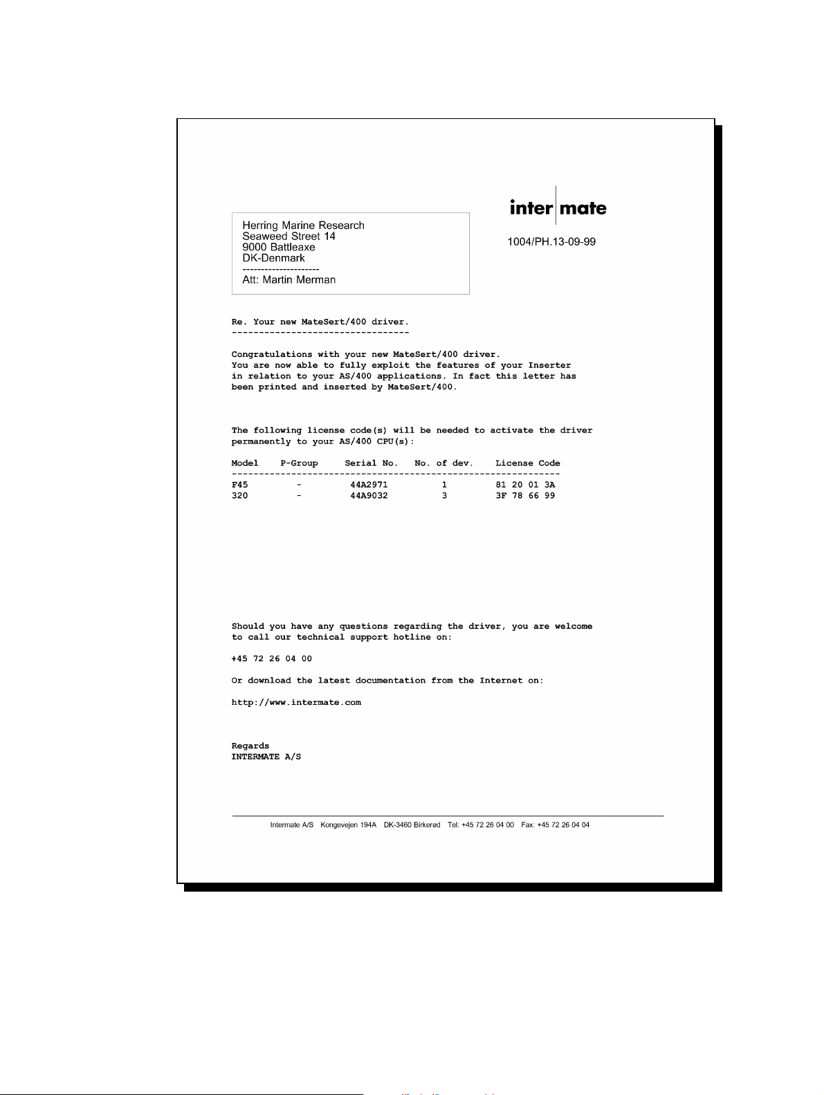
Illustration of the demo spool entry merged with the overlay IF400DEMO delivered with
InterForm400® (The illustration is a screen shot of the InterForm400
®
PCL viewer
function:):
32 User’s Manual for InterForm400
®
Page 33

Menu Structures and General Operation
The InterForm400® system can be included in one of your menus and can be called from
here (refer to the section Relations to other applications page 362). You can also
enter the InterForm400
APF3812/APFMENU
You will then be presented with the InterForm400
InterForm 400 - MAIN MENU System.......: INTER01
Workstn ID...: QPADEV0003
Select one of the following options: User ID......: PETER
Administrator: *ALL
1. Design overlay File set.....: PETER
2. Test print overlay Output queue.: PETER_5SI
3. Merge spool entry with overlay library...: QGPL
4. Work with overlay selectors Printer type.: HP4D
5. Work with Auto Forms Control Interface.: ASCII850
6. Work with Output Schedule Control Version......: 2006M01
7. Work with joint reports
8. Select file set
9. Select output queue and printer type
10. Work with actual output queue
80. Administering InterForm 400
90. Exit InterForm 400
Option: __
F3=Exit F6=Display messages F12=Cancel
®
system via a command line by entering:
®
main menu:
In the upper right corner of the display you will find a selection of information.
System: The system name of the AS/400 machine you are currently running on
(relevant when two or more systems are connected).
Workstn ID: The name of the workstation you are sitting at.
User ID: The name of your user profile.
Administrator: The user profile name of the InterForm400
®
system administrator. This
person is the only one who can use the option "Administering
InterForm400" on the main menu. If an administrator has not been
appointed this option is open to anybody.
File set: The name of the file-set you are currently operating on. Refer to Select
File set page 119 for further description.
Output queue: The name of the output queue for your session in the InterForm400
®
system when printing from within the menus (not via Auto Forms
Control).
Printer type: The default printer type of your session, which is only shown if the
administrator has allowed users to select Printer type (this is done under
option 9 on the main menu). Refer to page 374 for more information.
Interface: The protocol conversion mode you are using for the default printer.
User’s Manual for InterForm400® 33
Page 34

Version: The release number of InterForm400®, also reflecting the year of the
release. The number will be followed by an M##, which is the
modification number. M23 would mean modification 23.
At the bottom of the display you can see which command keys can be used everywhere
in the system. How to use them is only described here:
F3: Brings you back to the previous menu. In the main menu F3 exits the
InterForm400® system.
F12: Always takes you one screen backwards in the system.
F6: Displays the message queue.
Additionally using the ATTN key when your job is a group job will bring you out of the
InterForm400® system temporarily. When you return to the InterForm400® system you
will continue from the point at which you pressed ATTN.
34 User’s Manual for InterForm400
®
Page 35

1. Design Overlay
Note, that InterForm400® comes with a graphical designer. See Appendix O on page
461 and onwards to see how to install and use it.
In this menu overlay definitions and manipulation with spool data are defined.
Design InterForm 400 overlay APF300D
Overlay name __________ F4=List
F3=Exit F4=Prompt F12=Cancel
F13=Set view/print parameters
Overlay names can be up to 10 characters long. The first character must be a letter A-Z.
No blanks or special characters can be used in the name; ONLY "_" (underscore) is
permitted.
Selecting an existing overlay
Press F4 to get a list of existing overlays to select from or type the name of the overlay.
You may be refused access with the message ‘Overlay in use by user XXX in designer
job NNN’ a Graphical Designer job is editing the same overlay. If you are sure, that this
other job can be stopped you can do so by selecting option ‘80. Administering
InterForm400' and ‘52. Work with Designer job overlay locks’. Stop the job with option 4Remove.
Creating a new overlay
Type in a name of the overlay you want to create and press Enter
User’s Manual for InterForm400® 35
Page 36

Copy Overlay from Another Overlay
Type in a name of the new overlay you want to copy to and press Enter. Press F9 to
enter a overlay name to copy from and press Enter
Design InterForm 400 overlay APF300D
Name of overlay to copy from
_______________
F3=Exit F4=Prompt F9=Copy from another file set F12=Cancel
F10=Copy from another AS/400
Press F9 to enter a overlay name to copy from and press Enter, or press F10 to enter
the name of another AS/400 to copy from. You can then copy overlays from
InterForm400® on another AS/400 using DDM. (see page 270 for more information)
If the overlay is not known, or if placed in another file set press F9 once more to get a list
of file sets to choose from. Select the file set containing the overlay you want to copy
from, and select the overlay you want to copy.
36 User’s Manual for InterForm400
®
Page 37

Global settings of an overlay
The global settings of the overlay depends on the type of file set in which the overlay is
placed. These are the settings for file sets used for PCL printers and PDF output:
Design InterForm 400 overlay APF300D
Overlay name TEST
Overlay text __________________________________
Line spacing 040___ in 1/240 of an inch (*INPUT, 1-720)
Rotation 000___ (*INPUT, 0, 90, 180, 270)
Extra left margin
positions _0 (0-99)
Maximum number of
print positions 378 (1-378)
Extra blank lines
on top _0 (0-99)
Font 0066__ *INPUT, fontnumber F4=List
Extended page def. N (Y N)
Drawer / Papertype *PRINTER (*INPUT, *PRINTER, 1-255, Name) F4=List
Paper Size 0 F4=List
Pages per side __
Copy management N (Y N)
Duplex print N (N=no S=short edge margin L=long edge margin)
Duplex margin __0 in 1/240 of an inch (1-720)
Back page overlay __________ Code for placement _ (B=back page F=front)
F3=Exit F4=Prompt F11=Delete this overlay F12=Cancel
F13=Set view/print parameters F14=PCL-view
The data entered on this page describes how the spool file to be merged with this
overlay should be manipulated. The attributes (number of lines per inch, font etc.) of the
spool entry will be overwritten by these settings.
Overlay text: For your own information
Line spacing: Is dissolved in n/240 inch. For example 6 lines per inch corresponds to
40/240 inch. You may have been expecting to have to specify line
spacing in number of lines per inch. We have chosen this method to
give you a higher degree of freedom of choice. This setting can be
overwritten by Extended Formatting. By stating *INPUT the value is set
according to the attribute of the spool entry.
Rotation: Informs the system how the contents of the input spool entry should be
rotated on the paper. You may specify 000, 090, 180 or 270 degrees
(counter clockwise). The values 180 and 270 can only be used in
connection with IBM3812/16. In connection with other printer types these
values will be perceived as 000. By stating *INPUT the value is set
according to the attribute of the spool entry. The attributes *COR and
*AUTO is also inspected.
Extra Left
Margin: Number of character the print should be offset from the left margin.
Extra positions defined here will be included in Extended Formatting
Max Print pos: Maximum Print Position should normally be set to 240. However, in case
the spool entry, intended for merging with the overlay, contains
unwanted characters to the right, the number of print positions to be
truncated can be specified here.
Extra blank
lines: Extra blank lines inserted before line one of the spool entry. This value
can be suppressed by Extended Formatting.
Font: This font will be the global font for the entire spool entry unless
User’s Manual for InterForm400® 37
Page 38

otherwise specified by Extended Formatting or the overlay definitions
Remap Window and Tabulator. By stating *INPUT the value is set
according to the attribute of the spool entry
F4: Gives a list of available fonts. The standard IBM 3812 font ID’s is
predefined (refer to page 382 or look at the font list in the back of this
manual). Other fonts can be defined to the system and will then be
available here (See section 1. Description of additional fonts page 279)
Overview Fonts FNT100D
Type Selection, Press Enter.
1=Select Font
Select one of the following:
_ 0281 Gothic Text 20
_ 0290 Gothic Text 27
_ 0751 Sonoran-Serif 8-pt Roman Medium
_ 1051 Sonoran-Serif 10-pt Roman Medium
_ 1053 Sonoran-Serif 10-pt Roman Bold
_ 1056 Sonoran-Serif 10-pt Italic Medium
_ 1351 Sonoran-Serif 12-pt Roman Medium
_ 1653 Sonoran-Serif 16-pt Roman Bold
_ 2103 Sonoran-Serif 24-pt Roman Bold
_ 3998 MICR E-13B
_ 3999 POSTNET barcode
_ 9902 Sample - Univers 8p
_ 9903 Sample - Univers 10p
_ 9904 Sample - Univers 1p Bold
_ 9906 Sample - Univers 18p Bold
F3=Exit F12=Cancel
Extended
page def: When stating Y in this field you can override the global settings of Line
Spacing, Extra blank lines on top and Font. Formatting is done for
intervals of lines and is especially convenient if large areas of text
should be re-mapped or if you want to format the spool data into
columns.
Drawer: Depends on the printer type. Valid values are:
*INPUT = The drawer specified in the spool entry
*PRINTER = Printer default paper source
1-255 = Printer specific paper source
Name = Paper type (prompt with F4 to list valid types)
The values 1-255 is inserted in the HP PCL command Esc&l#H (see
Cassette Selection page 376). For details about how to select drawer
by use of paper type refer to page 331 and 376.
Paper Size: Is only visible if you have allowed individual paper sizes for the overlays.
If you specify 0 in Paper Size the default value from the administration
menu option 2. Configure InterForm 400 will be used for this overlay
(more info page 269).
Pages per
side
(Multi-up): Blank or 1 indicates no multi-up functionality. When 2 or more are
indicated, the overlay definitions Tabulator and Remap Window will be
able to handle the total number of lines set for the Multi-up.
38 User’s Manual for InterForm400
E.g. a spool page has 66 lines and multi-up is set to include 2 spool
pages on one laser printed page. A Tabulator will then be able to
handle line 1-132 (2 x 66), resulting in both spool pages will have the
same tabulator. The same applies for the Remap Window. The spool
pages included in the multi-up function could also be formatted in
®
Page 39

separate ways. I.e. removing of headers and footers of the additional
pages included in multi-up print.
Copy
Management: Stating N in this field, will enable you to define advanced pagination
within the overlay for use with spool entries consisting of different types
of contents (see using Page control page 52).
Stating Y will enable you to create several copies of each page. Also
design elements can be dedicated to specific copies. This is for instance
used when making copies of Invoices where the overlay for the copy
should have basically the same elements as the original but should be
characterized by the text “COPY” printed across.
Duplex options
These options are only visible if you have selected duplex print for the actual file-set
(Option 5. Create/Delete Overlay File Sets page 273). If the field Duplex print is filled
in with N, only the front of the paper is used.
Duplex
print: If you answer S or L in the Duplex print field, both sides of the paper is
used, including the answer you have given about the duplex margin
being at the long or short edge of the paper. When filling in S or L for
Duplex print together with N for Copy Management the Page Control
on the Design Overlay screen will be extended to include selection for
restricting overlay to odd or even pages (See Page control page 52)
Forced front
page: Controls if the overlay for which the Duplex function has been selected,
always should be printed on a front page, when a overlay selector is
used. By stating *YES, you will avoid that an intended first page is
printed on the duplex side of the previous page.
Duplex
margin: This value in the field states the width of the binding margin in n/240
inch.
Back page
overlay: This field can be left blank meaning that you want to use the same
overlay on both sides of each sheet. If the field is filled in with an overlay
name, only the front pages will be used for print and the back pages will
contain the back page overlay without any spool data.
It is however, possible to put variable data on both sides of the sheet
with different overlays, by leaving this field blank, and using suboverlays. A simple “main” overlay should be made, that contains two
sub-overlays calls only. In the two If..then lines in the main overlay, the
field “number of lines to remap”, will indicate the lines the sub-overlay
should process. All formatting must be handled by the sequence lines in
the sub-overlays.
Entering *VAR in this field will bring up a screen, where the conditions
for selecting the overlay must be stated. Note that *VAR can only be
used with Code for placement=B (or blank):
User’s Manual for InterForm400® 39
Page 40

Design InterForm 400 overlay APF300D
Overlay name TEST
Overlay text
Line spacing 040 in 1/240 of an inch (*INPUT, 1-720)
Rotation 000 (*INPUT, 0, 90, 180, 270)
Extra left margin
positions ............................................
Maximum number of : Variable Back Page Overlay :
print positions : :
Extra blank lines : Prefix . . . . . ______ :
on top : Line number . . ___ :
Font : Position . . . . ___ - ___ :
Extended page def. : :
Drawer : :
Paper Size : :
Multi-up : F3=Exit F12=Cancel :
Copy management : :
Duplex print :..........................................: edge margin)
Duplex margin 0 in 1/240 of an inch (1-720)
Back page overlay *VAR Code for placement B (B=back page F=front)
F4=Prompt F11=Delete this overlay F12=Cancel
F13=Set print parameters
Prefix The first part of the back page overlay name. The
overlay which is called by this function consists of this
prefix plus the character string found by Line number
and Position. For instance if the prefix is INV, and Line
Number and Position finds the string 001, the back page
overlay should be named INV001.
The Prefix must consists of minimum 1 character, which
can not be a number. The Prefix plus the string found
with Line Number and Position can not exceed a total of
10 characters.
Line Number: The print line in the spool entry defining the last part of
the back page overlay name.
Position: The column interval containing the last part of the
overlay name.
Code for Placement: The possibility of placing the back page overlay on the
front of the physical printed page is a unique feature of
the system, which overcomes a common problem for
duplex printing on pre-printed forms. Normally a HP
printer will print the back page of a duplex print first in
order to have it faced down in the output tray. This
means pre-printed forms has to be turned upside-down
in the input paper tray depending on the print being
simplex or duplex. When stating F (front) as code for
placement you will not have to do this, as the system will
reverse the order before printing.
J TIP J
An easy way of making “short bind” duplex, is to define the front page overlay as
normal, but rotate the back page overlay 180 degrees.
Function keys for display of a spool file
F13: Set view/print parameters:
This function is used to set the attributes of the spool file you want to merge the
overlay with. This must be done prior to selecting F14, F18 or F19.
40 User’s Manual for InterForm400
®
Page 41

Select Parameters for view / Print APF730D
Overlay name __________
or Overlay Selector ________
Primary/Secondary set _ 1=Primary 2=Secondary
Spooled file:
Job name __________
User __________
Job number ______
File name __________
Spool file no. ______ Number, *ONLY, *LAST
Code page ______ Number, *INPUT
Form type A4________
Copies __1 (1-255)
Drawer / Paper type *PRINTER__ (*PRINTER, *INPUT, *OVERLAY, 1-255, Name)
View format _ 1=PCL 2=B/W PDF 3=Color PDF
Name of output queue to search if spooled file is unknown:
Output queue __________
Library __________
F3=Exit F4=List overlays
Overlay Name Name of an overlay in the file-set you want to view together with
a spool file when using the PCL viewer (F14). This is required,
though the information is used for PCL viewing only.
Primary/
Secondary Set: If you have defined Copy Management for the overlay (see
page 53 and 46) you can test if you have made the correct
selection of overlay elements, by printing the overlay elements
for one of the two sets only. If this field is left blank (default) the
system will as default pick the Primary set.
Overlay Selector: If you have defined an Overlay Selector you can test if it is able
to pick the correct overlay. In this case Overlay Name above
must be blank. (refer to section Working with Overlay
selectors page 122)
Spooled File: Spooled file attributes can be entered here.
There is an alternative to typing all the information manually. If you type the name of an
output queue in the bottom of the screen and press Enter, you can fetch the
information about the spool entry from a view of the selected output queue by selecting
with option 1:
User’s Manual for InterForm400® 41
Page 42

Work with Output Queue
Queue: PRTHP3 Library: QUSRSYS
Type options, press Enter
1=Select 2=Change 3=Hold 4=Delete 5=Display 6=Release 8=attributes
Opt File User User Data Sts Pages Copies Form Type Pty
1 QPRINT INTERMATE INVOICE RDY 1 1 *STD 5
_ QPRINT INTERMATE PROFIT RDY 5 1 *STD 5
Parameters for option 2
===> __________________________________________________
F3=exit F11=View 2 F12=Previous F21=Description F24=More keys
Code page: This defines if a specific code page should be forced for the
spool entry. *SYSVAL means that the default code page
specified for the system will be used, unless a specific code
page is defined as attribute for the spool entry.
Form type: The Form type of the resulting printout. Default *STD
Copies: 1-99
Drawer: Overwrite the drawer settings of the overlay global settings.
For details about how to select drawer by use of paper type refer
to page 331 and 376.
View: You can specify what you want to view when you press F14 in
overlay design. If you choose ‘1=PCL’ pressing F14 will display
the result of a merge to PCL - in SwiftView. Choosing option 2 or
3 will make InterForm400® create a PDF file and display it using
Acrobat Reader (assuming that Acrobat Reader is associated
with PDF files on your PC). Refer to page 430 for more
information.
G NOTE G
In order to get PDF output you need to purchase the PDF module or the classic
package for InterForm400.
Output Queue: The name of the output queue where the spool entry to be
merged is placed.
Library: The library of the above output queue. If left blank the library list
will be used.
F18: DSPSPLF
With the Remap Window this function is relevant for displaying the spool entry in
order to determine lines and columns for the Remap Window. F18 prompts the
command DSPSPLF with the job information set by F13 Set view/Print
parameters, or by in menu 3. Merge spool entry with overlay (page 117).
Pressing F18 will only appear if this has been set prior to entering this menu .
42 User’s Manual for InterForm400
®
Page 43
F19: DSPPFM
This function works like F18, but prompts the commands DSPPFM for displaying
the spool entry as a physical file. This is useful for revealing reprinted lines
(bolding), which is not displayed with F18 DSPSPLF.
Remember to subtract the first 4 positions containing SKIP/SPACE information,
when calculating coloumn positions in the DSPPFM view..
Considerations for Zebra overlays
G NOTE G
Creation of ZPL output in InterForm400 requires purchase of the ZPL module or the
classic package.
For overlays intended to be used for label printers the Design Overlay screen will look
like this:
Design ZEBRA overlay ZEB300D
Overlay name TEST
Overlay text _______________________________________________
Label length __.000
Label width __.000
Temperature _0_ -30 - 30
Print speed 2 2, 3, 4, 5, 6, 8 inches/second
Line spacing 040___ in 1/240 of an inch (*INPUT, 1-720)
Rotation 000___ (*INPUT, 0, 90, 180, 270)
Font 0012__ *INPUT, fontnumber F4=List
Copy management Y (Y N)
F3=Exit F4=Prompt F11=Delete this overlay F12=Cancel
F13=Set print parameters
The especially Zebra related parameters are:
Label length/width:
The length and width of the labels to print on.
Temperature: The temperature to use for the printing head. This number is a relative
value (-30 to 30) for the temperature to use for the print head of the
Zebra printer. This value will be added to the Darkness value specified
on the printers display. That is if Darkness is 10 and temperature is 5 the
actual Darkness value for merges with this overlay will be 15. If the sum
of temperature and Darkness is outside the range 0-30 the nearest
value is used.
Print speed: Specify the printing speed in number of inches per second. Note, that
the highest possible print speed varies from one model to another.
J TIP J
If you want to insert text, frames or images in reverse i.e. white on black background
you can do it by first adding a frame with black filling (=pattern) and then place the text or
User’s Manual for InterForm400® 43
Page 44

image on top of the black frame (without specifying white in an Ink command). In this
manner you reverse the part of the text or image, that overlaps the black frame.
G NOTE G
Make sure, that the label length stated is correct. If not this will affect the positioning of
elements placed with rotation 90 and 270.
M WARNING M
Use a relatively low temperature e.g. 0 in order to avoid burn through of the ribbon and
potential damage to the print head. The wear of the print head increases when using a
higher temperature (or using a lower distance between paper and print head).
J TIP J
The print speed and temperature are related i.e. a higher speed might require a higher
temperature and for lower speeds a lower temperature may be sufficient.
J TIP J
Regarding barcode printing on label printers: If possible it is a good idea to place the
lines of the bars parallel with the travelling direction of the paper. In such a setup the
print head will not need to cool off and heat up for each bar thus making it possible to
print faster and use a lower temperature/Darkness setting.
G NOTE G
The actual commands within a merged Zebra spooled file is ZPL. That is the main
reason why you cannot view the overlay or the merged result using SwiftView or Acrobat
Reader. So when designing for Zebra you need to do test prints instead of viewing the
result graphically.
44 User’s Manual for InterForm400
®
Page 45

Extended Page Definition
Extended formatting is used to format intervals of lines from the spool entry. This
method can be used as alternative to using the design command type 9. Remap
Window, and will work with 8. Tabulator lines
If the global setting Extended Page Definition equals Y, the following screen will be
displayed
Update extended page definition APF305D
Overlay name: MYDEMO Overlay text: Mydemo
Type option, Press Enter.
2=Change 3=Copy 4=Delete 5=Display 8=Start AFC-job 9=End AFC-job
From Top- Left Line-
Opt linenbr. margin margin spacing Font
(No extended page definitions - Press F6 to create.)
End
F3=Exit F5=Refresh F6=Add F12=Cancel
The Global settings Line Spacing, Extra blank lines on top and Font will be decisive
until the first line of extended page definition is met.
From line number: A line number of the spool entry, from which the formatting
should change. The formatting will be valid until a new line
number is defined.
Top margin: Absolute margin from top edge of the page dissolved in whole
inches and pels (see Measuring formats page 48).
Left margin: Absolute margin from the left edge of the page dissolved in
whole inches and pels (see Measuring formats page 48). Note
that this value will be added to the leftmargin value of the
overlay command type 8. Tabulator.
Line spacing: Measured in n/240". For instance 6 lines per inch (1/6") will give
the value 40.
Font: The font ID of the formatted text.
F4: Prompting of the font list
F18: This function will display the spool entry with the job information
used for merge in option 3. Merge spool entry with overlay
(page 117). Pressing F18 will only work if this merge has been
made prior to entering this menu.
User’s Manual for InterForm400® 45
Page 46
Copy Management
Copy management is used to define the number of copies one single overlay should
produce when triggered. The following screen will automatically appear when pressing
Enter from the global settings menu where Y is filled in for Copy Management :
Design InterForm 400 overlay APF300D
Overlay name: IF400DEMO Overlay text: Demo overlay for InterForm 400
Number of copies of each page
Primary set . . . . . . . 2_________ 1-9, *VAR, *INPUT
Secondary set . . . . . . 1_________ 1-9, *VAR, *INPUT
F3=Exit F12=Cancel
Two sets of copies each consisting of up to 9 copies from a single spool entry can be
defined. The overlay elements (boxes, lines, images etc.) used on the primary and the
secondary sets can be different according to the definitions of a single overlay (See
Copy Management page 53)
Primary set: A value of 1 to 9 copies can be defined.
By selecting *VAR you will be able to define a line and a column
number in the spool entry where the desired number of copies
are specified. This of course requires the application to insert
this in the spool entry.
*INPUT will use the COPIES attribute of the original spooled file.
Notice however, that values higher than 9 will be interpreted as
1.
When used with Auto Forms Control this set (*PRI) is the
default set to be used in 1. Merge with overlay (see page 140)
Primary set . . . . . . . *VAR Print line Position
Secondary set: This is basically just an extra set of copies made from the same
spool entry. The secondary set is mainly intended to be used to
create an extra set with a fixed number of copies, independent
of the variation of copies in the main set. Stating a number for
“Secondary set” will not force a printout of this set. The
secondary set will only be printed if the Auto Forms Control
definition 1. Merge with overlay states Primary /Secondary
set=*SEC. (see page 140), or if you in 3. Merge spool entry
with overlay (page 117) have stated 2=secondary.
46 User’s Manual for InterForm400
®
Page 47
Source Drawers for Copies
After having stated the number of copies, pressing Enter will extend the screen to
include definitions of source drawers:
Design InterForm 400 overlay APF300D
Overlay name: IF400DEMO Overlay text: Demo overlay for InterFomr400
Number of copies of each page
Primary set . . . . . . . 2 *VAR, 1-9
Secondary set . . . . . . 1 *VAR. 1-9
Select paper from the following drawers:
Copy Primary Secondary
1 __________ __________ Valid drawers
2 __________ 1-255
Valid paper types:
F4=List
Do you want stapling . . Y/N _
F3=Exit F12=Cancel
F13=Set view/print parameters F14=PCL-view F18=DSPSPLF F19=DSPPFM
Here you can define from which drawer each copy should be taken from.
See Cassette Selection page 376 for more information of selecting by drawer number.
Refer to page 376 and 331 for information of how to select drawer by paper type.
M WARNING M
Different printer manufacturers have diverting opinions of which value should
correspond to which physical drawer. Therefore please consult your printers technical
reference to verify the drawer mapping.
Stapling
This option defines if the copies should be stapled. This option can only be used on the
printers stated below. Remember to use printer type HP4_PJL or HP4D_PJL when
merging.
Design InterForm 400 overlay APF300D
Overlay name: TEST Overlay text:
Number of copies of each page
Primary printout . . . . . 2
Secondary printout . . . ..................................................
: Stapling primary printout :
Select paper from the follo : :
: Select printer type for stapling :
Copy : :
1 : printer type 1=HP5Si Mopier :
2 : 2=Lexmark Optra N :
: 3=IBM NP24 / IP32/40 :
: 4=Kyocera 7000/9000 :
: 5=Xerox N24 / N32 / N40 :
: 6=Xerox DC 240/255/265 :
: 7=Océ 3165 :
: Notice: Stapeling requieres use of :
Do you want stapling . . Y/ : printertype HP4_PJL or HP4D_PJL. :
: :
F3=Exit : F3=Exit F12=Cancel :
F13=Set print parameters :................................................:
User’s Manual for InterForm400® 47
Page 48

Measuring Methods
All coordinates entered in InterForm400® must be dissolved into inches and pels.
Digits before the decimal point specify inches, and the digits after the decimal point
specify pels and must not exceed 239. An inch is dissolved into 240 pels.
Examples of values:
1" 1,000 = 1,000
1 ½” 1,(240/2) = 1,120
1 1/6" 1,(240/6) = 1,040
1 5/6" 1,(240/6 x 5) = 1,200
1,85" 1,(240 x 0,85) = 1,204
You will notice that it would be most convenient to use a ruler indicating lines per inch.
When multiplying and subtracting values it might seem a little more complicated, the
following are examples and the formulas used to solve it:
3,100 + 1,200 = 4,+300 => 4+1,(300-240) = 5,060
3,100 - 1,200 = 2,-100 => 2 -1,(240-100) = 1,140
Orientation of design elements
All positions are measured absolute to the upper left corner of the page, but depending
on the type of overlay element and rotation of the page:
Text, Images, PCL files. Relative to the upper left corner depending on the
rotation specified by Rotation under global settings.
Frames and lines: Relative to the upper left corner of a Portrait page,
regardless of the rotation specified in the global
settings.
J TIP J
You can print out a ruler from the Service menu option 4. Print ruler (see page ?). If
you will use an ordinary ruler, it is an advantage to find one with indication of 6 lines per
inch. Using the overlay “ruler” in file set “sample”, as an sub-overlay is also a method
for easy positioning of overlay elements and spool data.
48 User’s Manual for InterForm400
®
Page 49

The Design Screen
Note: Refer to Appendix O on page 461 for information of how to install and use the
InterForm400
®
graphical designer.
When you press Enter from the previous screens you will finally reach the screen where
the entry of overlay elements are made:
Design InterForm 400 overlay APF300D
Overlay name: IF400DEMO Overlay text: Demo overlay for InterForm400
Seqnbr. Type Overlay definition
Seqnbr. Type
______
F3=Exit F5=Service F12=Cancel F18=View Spool entry
An overlay consists of a number of sequence lines, each defining a part of the overlay like
frames, lines, text constants etc.
When entering a screen with existing sequence lines the last entered lines will be
displayed. The system simply believes that you intend to continue entering overlay
elements
You can scroll through the lines using page-up and page-down.
Each line in the overlay definition is accessed via its sequence number. If you select an
existing sequence number you will be able to update or delete this particular line. If you
select a line number not already in the definition it means you wish to add a new line.
Sequence numbers can be entered with 1 decimal position. This opens up the possibility
of inserting a new line anywhere in the definition, as the specification of a line with a
decimal results in the addition of 1 to the sequence numbers of all succeeding lines in the
definition. The new line is placed in the vacant space in the reference series. As example
entering 12,1 will insert a sequence number between line 12 and 13. When saved the
inserted sequence line is assigned number 13 and the following lines are incremented by
one.
After entering a sequence number press the Field Exit key to add or edit this line. The
key mapping of keyboards varies from one PC to another. The Field Exit key could be
assigned to e.g. the right Ctrl key, the Enter key or the ‘+’ key of your numeric keyboard.
User’s Manual for InterForm400® 49
Page 50
Service Options
By pressing F5 you will get a list of service options:
Design InterForm 400 overlay APF300D
Overlay name: IF400DEMO Overlay text: Demo overlay for InterForm 400
Seqnbr. Type Overlay definition
Select one of the following options:
1. Move the placement on the page
2. Move definitions to another sequence number.
3. Copy definition into this overlay
4. Delete lines
5. Resequencing
6. Print overlay definition
Option: __
With these you can organize the overlay definitions:
1. Move the placement on the page
Here you can enter an interval of sequence lines and adjust them horizontal and
vertical in a single action instead of changing entering each line.
In this function you can move the overlay up/down or left/right on the page.
Line interval to be moved . . . . . . : 0000_ - 0000_
Distance to move:
- to the right +/- _______
- downwards +/- _______
2. Move definitions to another sequence number
If you made a lot of lines, you might want to reorganize them in order to get a
better overview. With this option you define an interval of sequence lines to be
moved to another line number.
In this function you can move an interval of definition lines to another
sequence number.
Sequence number from/to to be moved . . . . 0000 - 0000
Inserted at sequence number . . . . . . . . ___1
3. Copy definitions into this overlay
This option allows you to copy definitions in the same overlay or from another
overlay
50 User’s Manual for InterForm400
®
Page 51
In this function you can copy lines into this overlay definition.
Overlay to be copied from . . . . . . . . TEST______ blank = this overlay
Sequence numbers from/to to be copied . . 0000_ - 0000_
Inserted at sequence number . . . . . . . ___1_
F4 = overview overlays
F24 = shift to look at FROM-overlay
4. Delete lines
This option you delete an interval of lines instead of entering each lines and press
F11.
In this function you can delete an interval of definition lines:
Interval . . . 0000_ - 0000_
5. Resequencing
If you have deleted lines you will get in the situation that you have free line
numbers to insert new overlay definitions on. This option will sort all remaining
lines numerical.
In this function you can resequence the lines in this overlay definition.
Press ENTER for resequensing. Press F12 for unchanged.
6. Print overlay definitions
This option will print out a detailed list of the existing overlay definitions on your
default printer.
User’s Manual for InterForm400® 51
Page 52
Overlay Element Selection Filters
When entering a sequence number and you press Field Exit the following entry screen
will appear:
Design InterForm 400 overlay APF300D
Overlay name: IF400DEMO Overlay text: IF400DEMO
Seqnbr. Type Overlay definition
Seqnbr. Type Page control
1,0 _ 1 = Frame 2 = Horizontal _ BLANK = all pages
3 = Vertical 4 = Line 1 = first page only
5 = Text 6 = Print-info 2 = page 2 and succ.
7 = Ink 8 = Tabulator 9 = last page only
9 = Remap window I = Image
? = If .. then F = PCL-file
G = HP-GL/2 file S = Suboverlay
* = Comment
F3=Exit F12=Cancel F18=View Spool entry
The right side of the screen will contain entries for Copy management or Page control
depending on the value for Copy management in the global settings of the overlay
Page Control
The Page Control fields are used to assign this specific sequence line to all printed
pages or to selected pages only.
The entry fields for Page control will appear if N has been selected for Copy
Management in the global settings of the overlay. (see Copy Management page 39)
Seqnbr. Type Page control
1,0 _ 1 = Frame 2 = Horizontal _ BLANK = all pages
3 = Vertical 4 = Line 1 = first page only
5 = Text 6 = Print-info 2 = page 2 and succ.
7 = Ink 8 = Tabulator 9 = last page only
9 = Remap window I = Image
? = If .. then F = PCL-file
G = HP-GL/2 file S = Suboverlay
* = Comment
F3=Exit F12=Cancel F18=View Spool entry
M WARNING M
Do not use page control in conditioned overlays. (The overlay called by an If..Then line).
If S or L is filled in for Duplex Print for the global settings of the overlay the Page Control
will be extended with a possibility of entering if page numbering should be made on odd or
even pages only:
52 User’s Manual for InterForm400
®
Page 53
Seqnbr. Type Page control
1,0 1 = Frame 2 = Horizontal _ BLANK = all pages
3 = Vertical 4 = Line 1 = first page only
5 = Text 6 = Print-info 2 = page 2 and succ.
7 = Ink 8 = Tabulator 9 = last page only
9 = Remap window I = Image _ BLANK = all pages
? = If .. then F = PCL-file 1 = odd pages
G = HP-GL/2 file S = Suboverlay 2 = even pages
* = Comment
F3=Exit F12=Cancel F18=View Spool entry
Copy Management
The entry fields for Copy Management will appear if Y has been selected for Copy
Management in the global settings of the overlay.(see Copy Management page 39)
Seqnbr. Type Copy management
1 1 1 = Frame 2 = Horizontal From To
3 = Vertical 4 = Line Primary _ _
5 = Text 6 = Print-info Secondary _ _
7 = Ink 8 = Tabulator
9 = Remap Window I = Image
? = If .. then F = PCL-file
G = HP-GL/2 file S = Suboverlay
* = Comment
F3=Exit F12=Cancel F18=View Spool entry
The Copy management field is used to assign this specific sequence line to all printed
copies or to selected copies only.
The following are examples of definitions for copy control:
Use this overlay element on all copies of Primary and Secondary sets (all fields left
blank):
1 1 1 = Frame 2 = Horizontal From To
3 = Vertical 4 = Line Primary _ _
5 = Text 6 = Print-info Secondary _ _
7 = Ink 8 = Tabulator
Use this overlay element on the first copy (the original) of the Primary set only:
1 1 1 = Frame 2 = Horizontal From To
3 = Vertical 4 = Line Primary 1 1
5 = Text 6 = Print-info Secondary _ _
7 = Ink 8 = Tabulator
Use this overlay element on the first copy of the Primary set and the first copy of the
Secondary set:
1 1 1 = Frame 2 = Horizontal From To
3 = Vertical 4 = Line Primary 1 1
5 = Text 6 = Print-info Secondary 1 1
7 = Ink 8 = Tabulator
Use this overlay element on all copies of the Primary set:
1 1 1 = Frame 2 = Horizontal From To
3 = Vertical 4 = Line Primary 1 6
5 = Text 6 = Print-info Secondary _ _
7 = Ink 8 = Tabulator
Use this overlay element all copies of both sets except the first one in the Primary set,
1 1 1 = Frame 2 = Horizontal From To
3 = Vertical 4 = Line Primary 2 6
5 = Text 6 = Print-info Secondary 1 6
7 = Ink 8 = Tabulator
User’s Manual for InterForm400® 53
Page 54

Overlay elements
Up to 9999 overlay elements can be made in one overlay.
1=FRAME
Seqnbr. Type Inch.pel Repetition
11,0 1 Frame Top edge ______ Move right ______
Left edge ______ Move down ______
Right edge ______ Extra times ___
Bottom edge ______
Thickness in pels ___ NW NE SW SE
Round/Sharp (R S) _ Radius __ __ __ __
Pattern _ F4=List
F3=Exit F11 = delete F12=Cancel F18=View Spool entry
Top Edge: Inches, pels absolute to the upper edge of a portrait page regardless of
Left Edge: Inches, pels absolute to the left edge of a portrait page regardless of the
Right Edge: Inches, pels absolute to the left edge of a portrait page regardless of the
the rotation specified by the global settings for the overlay.
rotation specified by the global settings for the overlay.
rotation specified by the global settings for the overlay.
Bottom Edge: Inches, pels absolute to the upper edge of a portrait page regardless of
the rotation specified by the global settings for the overlay.
Thickness
in pels: Thickness of a border in pels (1/240"). Zero means no border.
Round/Sharp: Determines whether the corners of the frame will be round or sharp. You
can also specify the radius in pels of each of the 4 corners (NorthWest,
NorthEast, SouthWest, SouthEast).
You can mix sharp and round corners by entering a radius in pels for the
corners you want round, and state zeros for the corners you want sharp.
If you specify R for round corners without entering radius in any of the 4
fields, the system will use the default value of 24 as radius for all 4
corners.
Unfortunately HPII, HPIID, HPIIP and other PCL4 printers can not draw
round corners. On those printers corners will always be sharp.
Pattern: Defines a fill pattern for the frame. Left blank means no pattern. Refer to
page 59 on how to use patterns.
Repetition
Move right: Inch,pels of the right movement of a duplicate of the frame relative to
the value for left edge
Move Down: Inch,pels of the vertical movement of a duplicate of the frame relative to
Extra times: Extra copies of the frame excluding the original. Extra copies will be
54 User’s Manual for InterForm400
the value for Top edge
displaced relative to each other according to the settings of Move right
and Move Down.
®
Page 55
NW: Radius in pels for the North West corner of the frame
NE: Radius in pels for the North East corner of the frame
SW: Radius in pels for the South West corner of the frame
SE: Radius in pels for the South East corner of the frame
Color
Printing: When working in a file-set defined for color printing, the frame definitions
will offer an additional pattern setting for color print. When having
selected a color INK setting prior to the frame settings, this color INK
selection will then be used for the printed frame and pattern. Frames
defined with Thickness in pels (if any), will always be printed as a solid
line.
Seqnbr. Type Inch.pel Repetition
3.0 1 Frame Top edge ______ Move right _______
Left edge ______ Move down _______
Right edge ______ Extra times ___
Bottom edge ______
Thickness in pels __3 NW NE SW SE
Round/Sharp (R S) S Radius __ __ __ __
Pattern, B/W-prt _ F4=List
Pattern, color-prt B F4=List
F3=Exit F4=Prompt F11=Delete F12=Cancel
F13=Set view/print parameters F14=PCL-view
2=HORIZONTAL LINE
Seqnbr. Type Inch.pel Repetition
1 2 Horizontal line
From top edge ______ Move right ______
Left end ______ Move down ______
Right end ______ Extra times ___
Thickness in pels ___
F3=Exit F12=Cancel F18=View Spool entry
From Top
Edge: Inches, pels absolute to the upper edge of a portrait page
regardless of the rotation specified by the global settings for the overlay.
Left end: Inches, pels absolute to the left edge of a portrait page regardless of the
rotation specified by the global settings for the overlay.
Right end: Inches, pels absolute to the left edge of a portrait page regardless of the
rotation specified by the global settings for the overlay.
Thickness
in pels: Thickness of a line in pels (1/240"). Zero means no border.
Move right: Inch,pels of the right movement of a duplicate of the line relative to the
value for left edge
Move Down: Inch,pels of the vertical movement of a duplicate of the line relative to the
value for Top edge
Extra times: Extra copies of the line excluding the original. Extra copies will be
displaced relative to each other according to the settings of Move right
and Move Down.
User’s Manual for InterForm400® 55
Page 56

3=VERTICAL LINE
Seqnbr. Type Inch.pel Repetition
1 3 Vertical line
From top edge ______ Move right ______
From left ______ Move down ______
Lower end ______ Extra times ___
Thickness in pels ___
F3=Exit F12=Cancel F18=View Spool entry
From Top
Edge: Inches, pels absolute to the upper edge of a portrait page regardless of
the rotation specified by the global settings for the overlay.
From left: Inches, pels absolute to the left edge of a portrait page regardless of the
rotation specified by the global settings for the overlay.
Lower end: Inches, pels absolute to the upper edge of a portrait page regardless of
the rotation specified by the global settings for the overlay.
Thickness
in pels: Thickness of a the line in pels (1/240"). Zero means no border.
Move right: Inch,pels of the right movement of a duplicate of the line relative to the
value for left edge
Move Down: Inch,pels of the vertical movement of a duplicate of the line relative to the
value for Top edge
Extra times: Extra copies of the line excluding the original. Extra copies will be
displaced relative to each other according to the settings of Move right
and Move Down.
4=LINE
Seqnbr. Type Inch.pel Repetition
n,0 2 Line
Endpoint 1 from top ______ Move right ______
from left ______ Move down ______
Endpoint 2 from top ______ Extra times ___
from left ______
Thickness in pels ___
F3=Exit F12=Cancel F18=View Spool entry
This definition works similar to the two previous definitions. It distinguish itself by enabling
lines to be diagonal. This also means you will have to define coordinates for each
endpoint.
Endpoint 1
From Top: Inches, pels absolute to the top edge of a portrait page
From left: Inches, pels absolute to the left edge of a portrait page
56 User’s Manual for InterForm400
regardless of the rotation specified by the global settings for the
overlay.
regardless of the rotation specified by the global settings for the
overlay.
®
Page 57

Endpoint 2
From Top: Inches, pels absolute to the top edge of a portrait page
regardless of the rotation specified by the global settings for the
overlay.
From left: Inches, pels absolute to the left edge of a portrait page
regardless of the rotation specified by the global settings for the
overlay.
Thickness
in pels: Thickness of a the line in pels (1/240"). Zero means no border.
Move Right: Inch,pels of the right movement of a duplicate of the line relative to the
value for left edge
Move Down: Inch,pels of the vertical movement of a duplicate of the line relative to the
value for Top edge
Extra times: Extra copies of the line excluding the original. Extra copies will be
displaced relative to each other according to the settings of Move right
and Move Down.
A limitation of this line definition is, that it is ignored when:
• using a HPII type (PCL4) of printer definition in InterForm
• used on back page overlays on HPII and HPIII type printers.
If you are making horizontal and vertical lines it is recommended that you use definition 2
and 3, and only use this definition for making diagonal lines.
5=TEXT
This can be used to insert text constants with varying fonts in the overlay.
Seqnbr. Type Inch.pel
26,0 5 Text constant From top edge ______
From left ______
Rotation ___
Font ____ F4=List
Text _____________________________________
_________________________________________________________________________________
______________________
F3=Exit F4=Prompt F12=Cancel F18=View Spool entry
From Top: Inches, pels absolute to the top edge of the rotation specified by the
global settings for the overlay.
From left: Inches, pels absolute to the rotation specified by the global settings for
the overlay.
Rotation: The available values for rotation are: 000, 030, 090, 120, 180, 210, 270,
300 degree. Values 180 and 270 can be used with HPGL/2 compatible
printers only (PCL5 or PCL5e). Values 030, 120, 210 and 300 requires a
HPGL/2 compatible printer.
Font: The font ID of the formatted text.
Text: Text field
User’s Manual for InterForm400® 57
Page 58

6=Print-info (Print information)
Seqnbr. Type Inch.pel
1.0 6 Print-info
From top edge ______
From left ______
Rotation ___
Font ___0 F4=List
Info-type __________ F4=List
F3=Exit F4=Prompt F12=Cancel
From Top: Inches, pels absolute to the top edge of the rotation specified by the
global settings for the overlay.
From left: Inches, pels absolute to the rotation specified by the global settings for
the overlay.
Rotation: The available values for rotation are: 000, 090, 180, 270 degree. Values
180 and 270 can be used with HPGL/2 compatible printers only (PCL5 or
PCL5e).
Font: The font ID used for printing out the information required below.
Info-type: Type of information to be printed (can be prompted with F4). Here you
can specify to either print out page numbers or information about the job,
that created the spool file.
Value: Prints out:
*PAGNBR Page number of the actual page.
*ENDPAGE Total number of pages.
*MUPPAGNBR The actual page number when using Multi-Up.
*JOBNAME The job name.
*USER Userprofile used for the job.
*JOBNBR Job number of the job.
*JOB All information above, about the job.
*PGM The program, that created the spool file.
*PGMLIB Library of the program, that created the spool file.
*OVERLAY The overlay, that has been merged with.
*FILESET File set of the merged overlay.
J TIP J
You can print out the text: ‘Page X out of Y’, where X is *PAGENBR and *ENDPAGE is
Y. Place the text ‘Page out of ‘ using option 5=Text, and then place the two
numbers using option 6=Print-info with *PAGENBR and another with *ENDPAGE.
58 User’s Manual for InterForm400
®
Page 59

7=INK (fill pattern for succeeding sequence lines)
Seqnbr. Type
1,0 7 Ink
Select ink for the succeeding lines
Pattern 8 blank = unchanged,
0 = 100% white shading,
1-8 = 1-100% shading, ...
F3=Exit F12=Cancel
F13=Set view/print parameters F14=PCL-view
Normally the system overwrites whatever might be the original contents, while leaving the
background unaltered.
With this overlay element the Ink can be changed enabling printing white on black
background, a pattern transparently on another pattern etc. The possibilities are
numerous.
Pattern: For the pattern the following are valid:
0 100% white shading (erases background)
1 2% shading
2 10% shading
3 20% shading
4 35% shading
5 55% shading
6 80% shading
7 99% shading
8 100% shading
A 1% shading (600 DPI)
B 3% shading (600 DPI)
C 6% shading (600 DPI)
D 8% shading (600 DPI)
E 24% sharding (600 DPI)
- Horizontal lines
! Vertical lines
/ Diagonal lines (to the right)
\ Diagonal lines (to the left)
+ Horizontal and vertical lines
X Crossing diagonal lines
Examples on use of Ink:
We have first made four large frames with fill pattern"\" (diagonal stripes \\\) (refer to page
? on how to print the pattern sheet).
In the sequence lines after, we have defined 4 small frames with fill pattern "!" (vertical
stripes |||) and 4 text constants printed with font 2103, which fits in the large frames.
In frame 1 and 2 we state an Ink just before the text line. You will notice, that the pattern
of the elements are placed on top of the previous placed elements.
If you want the small frame and text to be shown without the lines of the larger frame you
could choose to first place the same frame and text with fill pattern 0 (erase background)
before reprinting it with the wanted Ink as seen in frame 3. Here ‘!’ is used for the small
frame and ‘/’ is used for the text.
Frame 4 shows the result when choosing pattern = 0 (erase background) for the Ink and
printing TEXT. See the results below:
User’s Manual for InterForm400® 59
Page 60
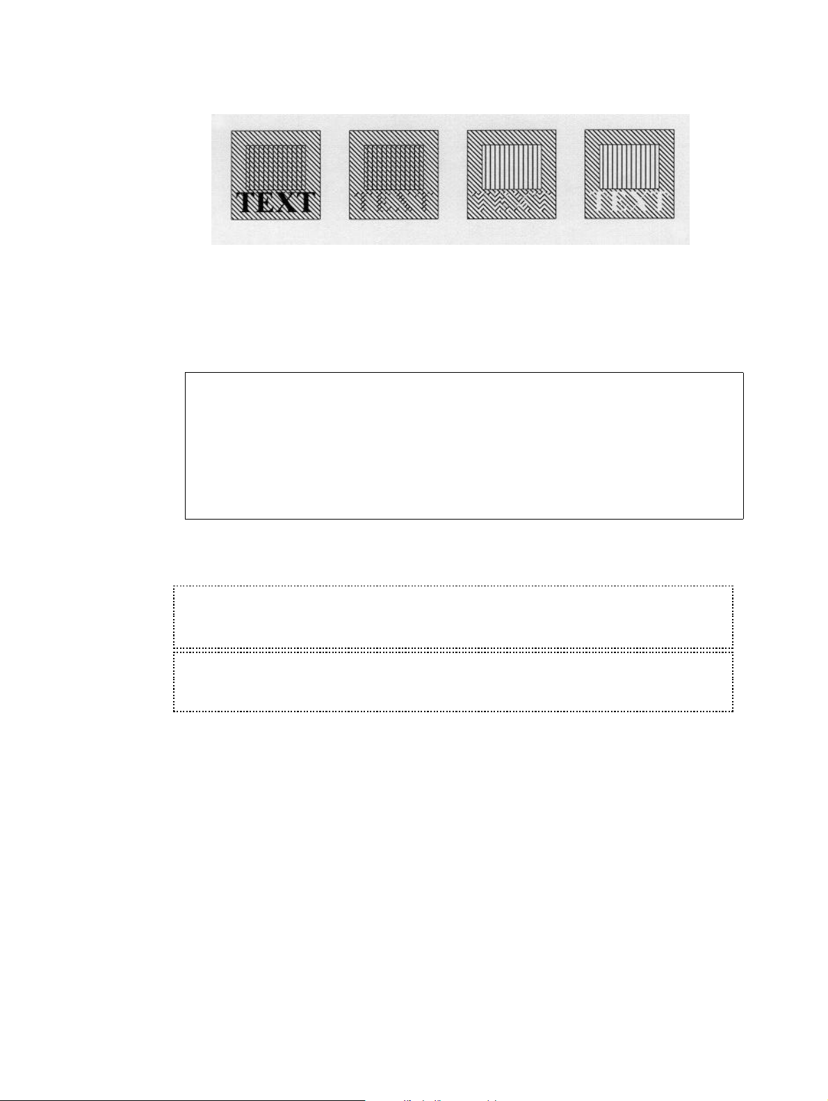
Black Ink Slash (/) Ink (0) Ink followed
(0) Ink
by Ink(/) / Ink(!)
You can also insert an image as a watermark, if you change the ink to be shading . Note
however, that you cannot use Ink to change PCL files into watermarks.
Color
Printing: When working in a file-set defined for color printing the INK settings will
have additional options, as per below.
Seqnbr. Type
2.0 7 Ink
Select ink for the succeeding lines
Pattern, B/W-prt _ blank = unchanged,
0 = 100% white shading,
1-8 = 1-100% shading, ...
Pattern, color-prt 8 (See above)
Color __3 1=Black, 2=Grey, 3=Red, ..
F3=Exit F4=Prompt F11=Delete F12=Cancel
F13=Set view/print parameters F14=PCL-view
This enables printing of spool data, text constants, lines and frames in color on PCL
compatible color laser printers.
L TROUBLE SHOOTING L
Remember to select a color printer when printing to a PCL compatible color laser printer
(HP5C, HP4500, HP4500D)
G NOTE G
Ink commands in main overlays will have not effect in conditioned suboverlays called
by If..Then.
60 User’s Manual for InterForm400
®
Page 61

8=TABULATOR (Paragraph tabulation)
A "tabulator" performs formatting and horizontal movement of an interval of lines in the
spool date. Almost the same result can be obtained by using command type 9. Remap
Window.
The line and position numbers to be entered are those appearing in the input, regardless
of a general margin or extra blank lines defined for the overlay.
Seqnbr. Type
1 8 Tabulator
Input: Line ___ - ___
Position ___ - ___
Print: From left edge ______ Adjustment _ (U L C R N B +)
Font ____ F4=List
Condition: Position ___ - ___
Is > = < N _ - ___________
Blank after _ B = Blank condition after
F3=Exit F4=Prompt F12=Cancel F18=View Spool entry
Input Line: The line interval to read including both lines entered here.
Input Position: The Column interval to read including both positions entered
here
From left: Inches, pels absolute to the rotation specified by the global
settings for the overlay. If moved beyond the paper edge (e.g.
14") the data will be removed from the data stream. Note that the
Left edge is measured from the physical paper edge unless the
line interval of the Tabulator is included in an Extended Page
Definition interval. In this case the Left Edge of the Tabulator is
measured from the Left Margin defined in the Extended Page
Definition.
Adjustment: Formatting of the text field. The Valid values are:
U Un-formatted. The area is printed without any changes
to formatting, and spaces.
L Left-adjustment. Spaces proceeding the first character
in text lines in the tabulator area are removed, causing
the area to be left adjusted at the position indicated by
From Left.
C Centred. Spaces within the tabulator area before and
after text lines are being removed, and the area is
centred around the position indicated by From Left.
R Right-adjustment. Spaces following the character in text
lines in the tabulator area are removed, causing the area
to be right adjusted at the position indicated by From
Left.
N Numeric. Indicates if the text lines in the tabulator area
should be considered as numbers (amounts).
B Print succeeding spaces in barcode data. Indicates if the
spaces in the coloumn interval succeeding the barcode
data should be converted to barcode. This only apply to
the barcodes 128 and 3of9. The barcodes will always be
left-adjusted. (Normally succeeding spaces will be
ignored.)
User’s Manual for InterForm400® 61
Page 62

+ Opens up for Extended Adjustement for definition of
Underline of text in the tabulator and/or lines of periods
(known as punctuation or dot leaders) made after each
line of the tabulator. The following options appear when +
is entered:
Adjustment: The adjustement of the underlined or
punctuated lines. Values U, L, C, R or N
acording to the above
Underline: Underlining of text in the tabulator
(spaces are not underlined).
Punctuation
Length: If the last position of a line in the tabulator,
defined by the second Input Position field, is a
period sign, a line of punctuation will be
printed. The punctuation will start after the last
printable character, and end at the position
(inches,pels) stated in this field counting from
the position stated in From Left. Only
Adjustment values U and L can be used. No
punctuation will be made if other values are
used, if no period sign is found or if the text
exceeds the punctuation length.
Font: The new font of the formatted text.
Condition: An optional set of values used if the tabulator should be executed
on a certain condition.
Position: Only activate the tabulator If a character string in the interval of
lines defined by the Tabulator matches this character string
according to the following condition.
Is >=<N Only run tabulator if this following field contains a text string or a
number which match one of the following valid operators:
> Greater than a number entered in the following field
= Equal to a number or a text string (case sensitive) or a
number entered in the following field.
< Less than a number entered in the following field
N Not equal to a number or a text string (case sensitive) or
a number entered in the following field.
A Acceptable characters. All the characters in marked
interval must be one of the characters in the following
field.
U Unacceptable characters. None of the characters in the
marked interval must be one of the characters in the
following field.
(See page 66 for a tip on use of ‘>’ and ‘<‘)
Blank After: Stating B will remove the text string or the number which has
been used for the condition from the resulting print out.
F18: With the Tabulator the function is relevant for displaying the spool
62 User’s Manual for InterForm400
entry in order to determine lines and columns for the tabulator.
F18 prompts the command DSPSPLF with the job information
used for merge in option 3. Merge spool entry with overlay
(page 117). Pressing F18 will only work if this merge has been
done prior to entering this menu.
®
Page 63
M WARNING M
If two or more overlapping tabulators are defined the first defined will take the text it
needs and leave blank positions in the relevant place for the next tabulator. A maximum
of 200 tabulators per overlay can be defined.
J TIP J
You can use a tabulator (left or unadjusted) to delete areas of text. Just tabulate the
area over the edge of the paper (e.g. 14"). This will not produce unnecessary code in the
data stream. InterForm400
printable area, and will then just ignore it. In case you have made many re-mappings you
can define a tabulator as the last sequence line which takes an area from line 1 to 72
and position 1 to 132, and move it outside the page, thereby deleting any remaining
data.
Extended Adjustment (+) does not support fixed width fonts e.g. Courier.
J TIP J
You can align numbers, where some are negative by use of numeric adjustment (N).
See below.
Input data is formatted for fixed pitch font tabulation
0 1 2
1234567890123456789012345
1 MICKEY MOUSE 1.100,00
2 refund EARS -2.100,00
3 total 1.000,00-
®
detects if the code is defined to be printed outside the
If the above was uncritically printed with a proportional spaced font we would experience
the result displayed below on the left, due to varying width of characters in the font.
If we made a tabulator that defined column 16 to 25 of line 1 to 3 to be printed with
numeric adjustment, we would get the result displayed to the right. Notice that the minus
is compensated for in the right alignment.
Proportional font without tabulator Proportional font with a numerical adjusted
tabulator
MICKEY MOUSE 1.100,00
refund EARS -2.100,00
total 1.000,00-
MICKEY MOUSE 1.100,00
refund EARS -2.100,00
total 1.000,00-
9=REMAP WINDOW (re-mapping text areas)
Definition of a Remap Window gives you the possibility of taking a particular part of a
given text line and print it elsewhere on the page, e.g. with rotation and another font.
A maximum of 300 Remap Window lines are allowed in one overlay. Additional remap
window lines are ignored. If this limitation is a problem you should use 'If..Then' lines
instead to create overlays, that are more efficient and easier to maintain. Contact your
local InterForm400 dealer to get more information of how to do that if in doubt.
User’s Manual for InterForm400® 63
Page 64

Seqnbr. Type
1 9 Remap window Input line ___ - ___ Position ___ - ___
Print: From upper edge ______ Line spacing . . ___
From left edge ______ Ignore blank lines _ (Y N)
Adjustment _ (U L R C N B E +)
Rotation ___
Font ____ F4=List
Blank original _ B = blank original version
Condition: Position ___ - ___
Is > = < N _ ____________________________
Blank after _ B = Blank condition after
Input Line: The line interval to read including both lines entered here. If the
end line is left blank or the same as the begin line, only one line
will be remapped.
Position: The Column interval to read including both positions entered
here. The maximum position interval is 198 characters.
Upper edge: Inches, pels absolute to the upper edge of the page according to
the rotation specified by the global settings for the overlay.
From left edge: Inches, pels absolute to the left edge of the page according the
rotation specified by the global settings for the overlay.
Line Spacing: Measured in n/240" which means 6 lines per inch will give the
value 40. Failure to fill in this value, will default to a linespacing of
zero resulting all text to be printed in one line.
Ignore Blank
Lines: Enabling this option will cause all blank lines to be discarded.
Adjustment: formatting of the character string. Valid values are:
U Un-formatted. The character string is printed without any
changes to formatting, and spaces.
L Left-adjustment. Spaces proceeding the first character
in the character string are removed, causing the string to
be left adjusted at the position indicated by From left.
C Centred. Spaces within the character string before and
after printable characters are being removed, and the
string is centred around the position indicated by From
left.
R Right-adjustment. Spaces following the character in the
character string are removed, causing the string to be
right adjusted at the position indicated by From left.
N Numeric. Indicates if the characters in the character
string should be considered as numbers (amounts).
B Print succeeding spaces in barcode data. Indicates if the
spaces in the coloumn interval succeeding the barcode
data should converted to barcode. This only apply to the
barcodes 128 and 3of9. The barcodes will always be leftadjusted.
E Full Justification. (aligning both left and right margins).
This function enables changes to the number of letters
per line, based on the font size and the max. line width
of the justification. Distance between words is
automatically adjusted.
Maximum line
width:: Defines the maximum length of the justified
text line.(Inch/pels)
64 User’s Manual for InterForm400
®
Page 65

Right margin
adjustment: Defines when a text line should not be
justified. This is based on the
percentage of text characters versus
blank spaces left on the last line of a
remapped paragraph.(0-100%)
Escape
sequences: Used when working with spool files
having escape sequences integrated.
(See Appendix H, page 390)
+ Opens up for Extended Adjustment for definition of
Underline of text in the Remap Window and/or a line of
periods (known as punctuation or dot leaders) made after
the text. following options appear when + is entered:
Adjustement: The adjustment of the underlined or
punctuation lines. Values U, L, C, R or N
according to the above.
Underline: Underlining of text in the Remap Window
(spaces are not underlined).
Punctuation
Length: If the last position of the text line in the Remap
Window, defined by the second Input Position
field, is a period sign, a line of punctuation will
be printed. The punctuation will start after the
last printable character, and end at the position
(inches,pels) stated in this field counting from
the position stated in From Left. Only
Adjustment values U and L can be used. No
punctuation will be made if other values are
used, if no period sign is found or if the text
exceeds the punctuation length.
Font: The new font of the formatted text.
Blank original B specifies, that the original text should be removed.
Condition: An optional set of values used if the remapping should be
executed on a certain condition.
Position: Only activate the Remap Window If the character
string read by the Remap Window matches this
character string according to the following
condition:
Is >=<N Only run tabulator if this following field contains a
text string or a number which match one of the
following valid operators:
> Greater than a number entered in the
following field.
= Equal to a number or a text string (case
sensitive) or a number entered in the
following field.
< Less than a number entered in the
following field.
N Not equal to a number or a text string
(case sensitive) or a number entered in
the following field.
A Acceptable characters. All the
characters in marked interval must be
one of the characters in the following
User’s Manual for InterForm400® 65
Page 66
field.
U Unacceptable characters. None of the
characters in the marked interval must
be one of the characters in the following
field.
(See page 66 for a tip on use of ‘>’ and ‘<‘)
Blank After: Stating B will remove the text string or the
number which has been used for the condition
from the resulting print out.
J TIP J
If you specify B for Blank original above, the text removed cannot be used for any
conditions (If..Then). If you want to combine the two, then do not blank the original in the
remap. Instead insert an additional line tabulating (type=8) the unwanted text outside the
page e.g. 14 inches from the left..
M WARNING M
Extended Adjustment (+) and Full Adjustment (E) does not support fixed width fonts
e.g. Courier.
M WARNING M
Even though you can remap text out of the visible paper, the text is still possible to find
the resulting PDF file when you merge with a spooled file. If you want to eliminate that
possibility use an unadjusted tabulator to remove the spooled file text.
J TIP J
If you want to compare a column of numbers (Right justified) to a specific value using ‘<‘
or ‘>’ and want to condition a ‘Tabulator’, ’Remap’ or ‘If..Then’ on the result, you should
include a space in front of the number, that you compare with.
This compare will work fine also for large numbers, that are much wider than the
compared value.
(Reason: A space (‘ ’) has a lower value than all digits ‘0'-‘9'.)
I=IMAGE
Seqnbr. Type Inch.pel
1 I Image From top edge ______
From left ______
Image name __________
Reverse Image _ R = Reverse Image
Resolution ___ 75,100,150,200,300,600
F4 = overview images F18=View Spool file
From top edge: Inches, pels absolute to the upper edge of the page according to
the rotation specified by the global settings for the overlay.
From left edge: Inches, pels absolute to the left edge of the page according the
Image name: The image imported under 8. Work with Images in the
Reverse Image: Entering R here will cause the image to be printed in negative.
66 User’s Manual for InterForm400
rotation specified by the global settings for the overlay.
administration menu. Refer to page 319 for details.
This option is meant to reverse images to normal in relation to
®
Page 67

some scanning utilities which saves TIFF reversed. Note, that
performance wise it is better to reverse if necessary during install
of the image in InterForm400 - refer to page 319 for more
information.
Resolution: The resolution by which the image was scanned. This option can
also be used to scale the image. For example an image scanned
in 300 dpi can be scaled to double size in the print out by entering
150 here. Entering 600 here will cause the same image to be
scaled to half size, but only if the printer supports a 600 dpi
resolution (HP4 and compatibles). The resolution of 200 dpi is
commonly used if the overlay is intended for faxing through the
BlueFax fax program also.
Color Printing: When working in a file-set defined for color printing the Image
settings will have an additional definition for color images. The
resolution of the color image can be adjusted from the original
settings, by stating an specific resolution for Horisontal and
Vertical values, respectively. (1-600 DPI).
If the resolution settings are left blank, the original resolution
settings of the imported image will be used.
The Black/White image definition is available to facilitate printing
of the same overlay both on black and white and color laser
printers.
.
M WARNING M
Note that you can not specify rotation. An image always has the orientation specified in
the global settings for the overlay.
?=IF...THEN (conditional nesting of overlays)
This feature is useful in the situation where the appearance of the overlay has to be
dependent of the text that is merged with the overlay. This can be caused by a spool entry
containing two or more different print outs, say invoices and credit notes, and where you
want different overlays on the individual printout.
Another use of the "If..then" feature is the case where a detail in the printout shall result in
adding an extra detail to the overlay (see example page 101). Finally the If..then feature
can be used for formatting print lines or groups of print lines appearing in random line
positions (see example page 107)
User’s Manual for InterForm400® 67
Page 68

Seqnbr. Type
1,0 ? If . . . . . Input line ___ - ___
Position ___ - ___
Is > = < N _ _________________________
Then . . . . Overlay __________ Nos. of lines to remap ____
Upper edge ______ A/+/- _
Left edge ______ A/+/- _
Blank after _ B = blank original text
F18=View Spool file
Input Line: The line interval to read including both lines entered here.
Input Position: The Column interval to read including both positions entered here
Is >=<N Only call the sub-overlay if this following field contains a text
string or a number which match one of the following valid
operators:
> Greater than a number entered in the following field
= Equal to a number or a text string (case sensitive) or a
number entered in the following field.
< Less than a number entered in the following field
N Not equal to a number or a text string (case sensitive) or
a number entered in the following field.
A Acceptable characters. All the characters in marked
interval must be one of the characters in the following
field.
U Unacceptable characters. None of the characters in the
marked interval must be one of the characters in the
following field.
(See page 66 for a tip on use of ‘>’ and ‘<‘)
Overlay: The name of the overlay to be used as sub-overlay. If the name
entered here is MACROxxxxx where xxxxx represents a numeric
number (e.g. MACRO00001) InterForm400® will make a PCL
macro call using this number. This will require the PCL macro to
be loaded into the printer prior to using the main overlay. The
PCL file can be loaded into the printer by the InterForm400
®
HPMACRO command (see page 402, 416).
Number of
lines to remap: This parameter is used to pass on a line interval to a sub-overlay
which can process the lines with Remap Windows or Tabulator
commands. The first line of the interval will be the line defined by
Input line of the line interval and will be regarded as line 1 in the
sub-overlay, i.e. the sub-overlay will consider the interval as a
virtual spool entry to process.
Defining *VAR for this function, will cause this If..then command
to continue checking all lines starting from the beginning of the
input line interval, until another If..then command is met,
provided that it is within the line interval of the original If..then
command. If conditions for more If..then commands are true
concurrently, the field Lines to remap is only used from the last
If..then command.
This feature is designed specifically to format item lines printed in
varying lines, and with varying number of lines between the item
groups (see example page 107).
68 User’s Manual for InterForm400
Vertical cursor repositioning
When you enter a number of lines to remap (other than 0) you
are prompted for a vertical repositioning like below:
®
Page 69

Vertical cursor repositioning
before execute of sub overlay
Position related to actual position
Number of pels . . ___ ( -99 - 99 )
Or reposition related to previus
non blank input line
Number of pels . . ___ ( 0 - 999 )
F3=Exit F12=Cancel
With this function you can vertically reposition the rest of the
spooled file i.e. move the spooled file contents and all relatively
positioned elements e.g. tabulators and remaps.
Position related to actual position:
This will move the rest of the spooled file up (negative value) or
down (positive value). See page 107 for an example which uses
this option.
Reposition related to previous non blank input line:
Use this repositioning e.g. in order to close the gap of blank lines
on the original spooled file. (Use the If..Then on the next non
blank line.)
Upper Edge: Inches, pels position according to the entry of the following field:
A Vertical position of the sub-overlay is made absolute to
the upper edge of the paper. Vertical positioning of
elements in the sub-overlay is added to this value.
+ The sub-overlay is re-positioned downwards relative to
the position of the string matching the criteria for the suboverlay to be called. Vertical positioning of elements in
the sub-overlay is added to this value.
- The sub-overlay is re-positioned upwards relative to the
position of the string matching the criteria for the suboverlay to be called. Vertical positioning of elements in
the sub-overlay is added to this value.
Left Edge: Inches, pels position according to the entry of the following field:
A Horizontal position of the sub-overlay is made absolute to
the left edge of the paper. Horizontal positioning of
elements in the sub-overlay is added to this value.
+ The sub-overlay is re-positioned to the right relative to
the position of the string matching the criteria for the suboverlay to be called. Horizontal positioning of elements in
the sub-overlay is added to this value.
- The sub-overlay is re-positioned to the left relative to the
position of the string matching the criteria for the suboverlay to be called. Horizontal positioning of elements in
the sub-overlay is added to this value.
Blank After: Stating B will remove the text string or the number, which has
been used for the condition, from the resulting print out.
M WARNING M
Global settings of the sub-overlay, inserted by the if..then line, will be ignored as well
as 6 = Print-info.
User’s Manual for InterForm400® 69
Page 70
M WARNING M
Up to 300 ‘If..Then’ lines can be defined for an overlay.
M WARNING M
Only one level of conditioned sub-overlays is possible.’If..Then’ lines placed in
overlays, which are called by ‘If..Then’ are never executed.
M WARNING M
Totally blank lines are not considered for the If..Then line i.e. a condition on one or
more blank characters on a totally blank line will not trigger a call of the suboverlay. The
OS/400 command DSPSPLF will show the lines which can be conditioned.
F=PCL-FILE
Insertion of a PCL-file might be one of the most important features of the system, as
designing forms more and more is a job for a PC. InterForm400® allows a single overlay
to be combined of several PCL forms as well as having standard elements included as
described in the previous sections.
When overwriting (updating) a PCL-file on the system all overlays referring to this PCL
resource will automatically be updated. An “encapsulated” PCL-file (including PCL and/or
HP-GL/2) generated in any PC application equipped with an HPII, HPIII or HP4 driver can
be transferred to the system by a File Transfer,a Virtual Print or copying between
shared folders by means of Client Access 400 (PC Support) (see Importing PCL
overlay from PC print file page 325).Note that inclusion of PCL-files for the
Printer/Interface type chosen as default, has to be confirmed under 2. Set default output
queue and printer type (page 268).
Seqnbr. Type Inch.pel
1.0 F PCL-file From top edge _______ (+ -)
From left _______ (+ -)
File name __________
The overlay element that defines the PCL file to be inserted is quite simple. It is, however,
possible to fine adjust the placement of the PCL form compared to the positions defined in
the original PCL-file. This frees you from starting up the PC applications if only the overall
placement needs to be changed.
From top edge Inches, pels vertical position of the PCL file is made absolute to the
upper edge of the paper. Vertical positioning of elements in the PCL file is
added to this value. Adding a minus after the value, will cause an
movement upwards. (e.g. 1,120- for 1½” negative movement)
From left edge Inches, pels horizontal position of the PCL file is made absolute to the
left edge of the paper. Horizontal positioning of elements in the PCL file is
added to this value. Adding a minus after the value, will cause a
movement to the left. (e.g. 1,120- for 1½”movement to the left)
Color
printing: When working in a file-set defined for color printing the PCL-file settings
will have an additional definition for color PCL-files.
The Black/White PCL-file definition is available to facilitate printing of the
same overlay both on black and white and color laser printers.
70 User’s Manual for InterForm400
®
Page 71

M WARNING M
The system does not check the contents of the PCL file to be PCL4, PCL5 or PCL5e
code. Printing code made for a PCL5e on a PCL5 printer might cause problems, as well
as printing PCL5 on a PCL4 printer definitely will go wrong. It is recommended to use an
HPIII driver to create the PCL files on the PC
G=HP/GL-2-FILE
A HP-GL/2 file can be file transferred to the system for storage as a member in the
physical file APF3812/GL2. The PC file containing the HP-GL/2 code must be transferred
to the system by a File Transfer function.
This feature has been superseded by the PCL imports option. Contact Intermate A/S for
details, if import of HPGL files is needed.
Design APF3812 overlay APF300D
Overlay name: PROFIT Overlay text: Final Result DM /YTD
Seqnbr. Type Overlay definition
Seqnbr. Type Inch.pel
2,0 G HP-GL/2 file From top edge ______
From left ______
Height ______
Width ______
Rotation ___
Scale factor ______
Line width __
File name __________
F3=Exit F4=Prompt F12=Cancel
If you are using HP4 compatible printers only, you should choose to use the F=PCL-file
sequence line solely, as this will treat a HP-GL/2 files and PCL-files equally. This means
you can use the procedures for reading in PC-print into PCL-files explained on page 325
to retrieve the HP-GL/2 file from the PC environment instead of using the Client Access
(PC-support) file-transfer function.
From top edge Inches, pels vertical position of the HP-GL/2 file is made
absolute to the upper edge of the paper. Vertical positioning of
elements in the PCL file is added to this value. Adding a minus
after the value, will cause an movement upwards. (e.g. 1,120- for
1½” negative movement)
From left edge Inches, pels horizontal position of the PCL file is made absolute
to the left edge of the paper. Horizontal positioning of elements in
the PCL file is added to this value. Adding a minus after the
value, will cause a movement to the left. (e.g. 1,120- for
1½”movement to the left)
M WARNING M
Note that the system will wrap the HP-GL/2 code into a PCL macro when printing, and
only HP4 (PCL5e) printers allow HP-GL/2 code in PCL macros.
User’s Manual for InterForm400® 71
Page 72

S=SUBOVERLAY
If you are printing general company info in several overlays, i.e. the company letter head,
it is convenient to place this info in a separate overlay. With this function you can place
such information in an overlay that can be called as a sub-overlay from any other
overlays. Ie. changing e.g. the phone number only have to do be done in this overlay.
Design InterForm 400 overlay APF300D
Overlay name: Invoice Overlay text: Invoice overlay
Seqnbr. Type Overlay definition
Seqnbr. Type
1,0 S Suboverlay
Overlay name COMPINF
F3=Exit F12=Cancel
The name of the overlay to be used as sub-overlay. If the name entered here is
MACROxxxxx where xxxxx represents a numeric number (e.g. MACRO00001)
InterForm400® will make a PCL macro call using this number. This will require the PCL
macro to be loaded into the printer prior to using the main overlay. The PCL file can be
loaded into the printer by the InterForm400® HPMACRO command (see page 402, 416).
M WARNING M
Global settings of the sub-overlay, inserted by the S=Suboverlay, will be ignored as
well as 6 = Print-info.
* = COMMENT
This function will insert a comment in your overlay definition. Introducing a comment line
in the overlay definition is for easy overview purposes only and will not affect the resulting
print.
72 User’s Manual for InterForm400
®
Page 73

Seqnbr. Type Overlay definition
0001 * Insert Intermate Logo in Upper Right Corner
0002 I Image DEMOIMAGE Top 01.100 Left 04.180
0003 * Recepient Frame
0004 1 Frame top 01.100 left 00.200 right 04.120 bottom 02.160
0005 * Remap Recepient Adress into Recepient frame
0006 9 Remap window 06-011 pos 08-040 top 1.160 left 1.000 L
Seqnbr. Type
1.0 * Comment
Insert Intermate Logo in Upper Right Corner
User’s Manual for InterForm400® 73
Page 74
How the sequence lines in overlay design are executed
The execution order is of the sequence lines is depending on the type of the line. They are
executed in this order:
1st. Frames, Lines, Text (option 5), Print-info, Ink, Images, PCL-files, HP/GL-files
and Suboverlays.
2nd. 9=Remap Window
3rd. ?=If..Then
Last 8=Tabulator
Normally it is not necessary to remember this order, but when you mix them you could get
a problem: If you specify to blank out remapped text by use of option 9=Remap Window,
then you cannot use the text for a condition in If..Then. This can be solved by not blanking
out the text in the Remap Window and instead insert an 8=Tabulator to tabulate the text
out of the page after the If..Then has been executed.
If you have several ?=If..Then lines, remapping the same line(s), then only the last
condition met will have the lines remapped. The other conditional overlays are executed,
but no lines are transferred.
M WARNING M
A deviation from the rules above are seen if you transfer 2 or more lines to a suboverlay by use of If..Then. The second and following lines are transferred first - even
before any Remap Windows in the main overlay are executed.
G NOTE G
Ink lines in the main overlay will have no effect in conditioned sub-overlays (called by
If..Then).
G NOTE G
If you use absolute positioning for the sub-overlay called by If..Then you will notice this:
Tabulators in the sub-overlay are unaffected by the positioning of the sub-overlay.
Remap Windows in the sub-overlay add the vertical position specified in the If..Then
command whereas the horizontal position is ignored.
J TIP J
Regarding design of Zebra overlays: If you want to insert text, frames or images in
reverse i.e. white on black background you can do it by first adding a frame with black
filling (=pattern) and then place the text or image on top of the black frame (without
specifying white in an Ink command). In this manner you reverse the part of the text or
image, that overlaps the black frame.
74 User’s Manual for InterForm400
®
Page 75

User’s Manual for InterForm400® 75
Page 76

Getting Familiar With Overlays
The following sections are structured so you will be brought through a process of
improving the visibility of the sample spool entry IF400DEMO introduced in the Getting
Started section.
The chapter requires you have:
• Run the Getting Started section.
• A PCL5 capable printer attached to your default InterForm400® output queue
(displayed in the upper right field on the main menu), or have configured the PCL
Viewer
• Not made changes to the sample overlay IF400DEMO delivered with the system.
It is recommend that you have:
• Two terminal sessions available.
• Quiet surroundings
• A cup of coffee
You can start by printing the overlay IF400DEMO if you like to know how the final result
will appear.
Please abstract from the fact that it is not a piece of design artwork. We have
concentrated mainly on using as many features of the system as possible.
76 User’s Manual for InterForm400
®
Page 77
Step 1. Making a Work Copy of the Overlay IF400DEMO
In order to keep the original sample we should first make a copy of the overlays to work
with. To prevent the changes we make to be overwritten by future updates of the SAMPLE
file-set, we will do the changes in our TEST file-set which was created on page 28 in the
Getting Started section.
Enter 8 in the option field on the main menu::
Select File-set
Select one of the following file-sets, then press Enter.
1=Select
Opt File-ID Description
_ SAMPLE InterForm 400 Samples
1 TEST Test file-set
F3=Exit F12=Cancel
Now enter 1 In the option field to select TEST and press Enter
Now enter 1. Design Overlay on the main menu and press Enter:
Design InterForm 400 overlay APF300D
Overlay name MYDEMO_____
F3=Exit F4=List overlays F12=Cancel
Here we type the name of the new overlay we want to create. We can name this overlay
MYDEMO. We type MYDEMO and press Enter:
Design InterForm 400 overlay APF300D
Overlay name MYDEMO____
Overlay text __________________________________
Line spacing 040 in 1/240 of an inch (*INPUT, 1-720)
Rotation 000 (*INPUT, 0, 90, 180, 270)
Extra left margin
positions 0 (0-99)
Maximum number of
print positions 378 (1-378)
Extra blank lines
on top 0 (0-99)
Font 0066 *INPUT, fontnumber F4=List
Extended page def. N (Y N)
Drawer *PRINTER (*INPUT, *PRINTER 1-9, 20-39)
Paper Size 0 F4=List
Pages per side __
Copy management N (Y N)
Duplex print N (N=no S=short edge margin L=long edge margin)
Duplex margin __0 in 1/240 of an inch (1-720)
Back page overlay __________ Code for placement _ (B=back page F=front)
F3=Exit F4=Prompt F9=Copy from another overlay F12=Cancel
F13=Set view/print parameters F14=PCL-view
This screen already has some options filled in. All that will be overwritten by the settings of
the overlay IF400DEMO we are copying from. We notice that since we are actually
creating a new overlay it is possible to copy an existing overlay with F9. We press F9 to
User’s Manual for InterForm400® 77
Page 78
copy from another overlay:
Design InterForm 400 overlay APF300D
Name of overlay to copy from
__________
F3=Exit F4=Prompt F9 = copy from another file-set F12=Cancel
We know that the IF400DEMO overlay is in another file-set, so we have to press F9 once
more to get a list of file-sets to choose from.
...............................................
: Overview InterForm 400 file-sets :
: 1=Select :
: 1 SAMPLE InterForm 400 Samples :
: _ TEST Test file-set :
: :
: :
: :
: :
: F12=Cancel :
:.............................................:
F3=Exit F4=Prompt F9 = copy from another file-set F12=Cancel
We select file-set SAMPLE and press Enter:
...............................................
: Overview overlays :
: Start with: :
: 1=Select :
: 1 IF400DEMO InterForm400 demo :
: :
: :
: :
: :
: F12=Cancel :
:.............................................:
Now we select overlay IF400DEMO and press Enter:
Design InterForm 400 overlay APF300D
Overlay name MYDEMO____
Overlay text InterForm 400 Demo Overlay_______________
Line spacing _40 in 1/240 of an inch (1-720)
Rotation 000 (000 090 180 270)
Extra left margin
positions _8 (0-99)
Maximum number of
print positions 378 (1-378)
Extra blank lines
on top _4 (0-99)
Font _111 F4=List
Extended page def. N (Y N)
Drawer *PRINTER (*INPUT, *PRINTER 1-9, 20-39)
Paper Size 0 F4=List
Pages per side __
Copy management N (Y N)
Duplex print N (N=no S=short edge margin L=long edge margin)
Duplex margin __0 in 1/240 of an inch (1-720)
Back page overlay __________ Code for placement _ (B=back page F=front)
F3=Exit F4=Prompt F11=Delete this overlay F12=Cancel
78 User’s Manual for InterForm400
®
Page 79

We have now made a copy of the overlay IF400DEMO from file-set SAMPLE and stored it
by the name MYDEMO in file-set TEST.
Step 2. Make a Test Print of the Overlay+Spool Data
Before we start changing things we will make a printout of the overlay so we know what
we have to begin with.
We press F3 to exit to the main menu
Enter menu 3. Merge spool entry with overlay:
Merge Spooled File with Overlay APF730D
Overlay name MYDEMO____
or Overlay Selector __________
Primary/Secondary set _ 1=Primary 2=Secondary
Spooled file:
Job name __________
User __________
Job number _______
File name __________
Spool file no. _______ Number, *ONLY, *LAST
Code page ________ Number, *INPUT
Merge overprint lines *NO_ *NO, *YES
Form type *STD
Copies __1 (1-255)
Drawer / Papertype *PRINTER (*PRINTER, *INPUT, *OVERLAY, 1-256, Name)
Name of output queue to search if spooled file is unknown:
Output queue . . . . AFC_INPUT1
Library . . . . . APF3812___
F3=Exit F4=Prompt F12=Cancel
MYDEMO is already filled in because it was the last overlay active in the design menu.
Now go to the lower part of the screen and fill in queue AFC_INPUT1 and library
APF3812. In the Getting Started section page 30 we created a DEMO spool entry. This
is still placed in the queue with the description PRTCTL. If you can’t find the spool entry,
you can create it using option 1. Create demo spool entry (see page 337)
We press Enter to look at entries in queue AFC_INPUT1:
User’s Manual for InterForm400® 79
Page 80

Work with Output Queue
Queue: AFC_INPUT1 Library: APF3812
Type option, Press Enter.
1=Select 2=Change 3=Hold 4=Delete 5=Display 6=Release 8=Attributes
Opt File User User Data Sts Pages Copies Form Type Pty
1 QPRINT PETER PRTCTL HLD 2 1 DEMO 5
Parameters for option 2
===>__________________________________________________________________________
F3=Exit F11=View 2 F12=Cancel F21=Description F24=More keys
We select the file with option 1 and press Enter
Merge Spooled File with Overlay APF730D
Overlay name MYDEMO____
or Overlay Selector __________
Primary/Secondary set _ 1=Primary, 2=Secondary
Spooled file:
Job name DSP010700_
User PETER_____
Job number 073534
File name QPRINT____
Spool file no. 0005 Number, *ONLY. *LAST)
Codepage _____ Number, *INPUT
Form type *STD______
Copies _1 (1-99)
Drawer *PRINTER (*PRINTER *OVERLAY 1 2 3 4 5 6)
Name of output queue to search if spooled file is unknown:
Output queue . . . . __________
Library . . . . . __________
F3=Exit F4=Prompt F12=Cancel
We notice that all the spool file attributes have now been inserted.
We can now press Enter to print the Overlay MYDEMO merged with this spool entry and
we will automatically be returned to the main menu.
Compare your print out with page 32. In the next sections we will start to re-design the
overlay.
J TIP J
If you select option 3. merge spool entry with overlay again later you will notice that
the overlay name and the spool file attributes are remembered. That means we do not
need to select the spool file again for successive printout, as long as you do not leave
the InterForm400® menus..
J TIP J
An alternativ to printing the overlay is to use the function F14 PCL-View in the overlay
design window. This will allow you to verify the changes you make on the screen,
instead of printing them. The overlay and spool file attributes which you defined in this
80 User’s Manual for InterForm400
®
Page 81

section are remembered, which means you do not need to select F13 in the overlay to
set these attributes for PCL viewing. Refer to Appendix L - PCL Viewing
L TROUBLE SHOOTING L
No printout? select option 10 to view your output queue. Are there any messages ?. Is
the queue AFC_OUT1 still attached to your printer writer ?
Step 3. Entering the Design Window
Now we will enter menu 1. Design overlay again. MYDEMO is still remembered and we
press Enter until we get the design window:
Design InterForm 400 overlay APF300D
Overlay name: MYDEMO Overlay text: Mydemo
Seqnbr. Type Overlay definition
0001 I Image DEMOIMAGE Top 01,100 Left 04,180
0002 8 Tabulator lin.003-003 pos 72-072 left12,000L font 0011
0003 9 Remap window 06-011 pos 08-040 top 1,160 left 1,000 L
0004 1 Frame top 01,100 left 00,200 right 04,120 bottom 02,160
0005 9 Remap window 13-013 pos 57-072 top 1,220 left 5,200 C
0006 2 Horizontal top 10,120 left 00,200 right 07,120
0007 5 Text T10,160 L01,200 000° Font9902 Intermate A/S Kongev
Seqnbr. Type
______
F3=Exit F5=Service F12=Cancel
Here we have a list of the overlay elements we copied from the original IF400DEMO
overlay.
User’s Manual for InterForm400® 81
Page 82

Step 4. Printing the Overlay Definition List
Print out a list of the definitions by pressing F5:
Design InterForm 400 overlay APF300D
Overlay name: MYDEMO Overlay text: Mydemo
Seqnbr. Type Overlay definition
0001 I Image DEMOIMAGE Top 01,100 Left 04,180
0002 8 Tabulator lin.003-003 pos 72-072 left12,000L font 0011
0003 9 Remap window 06-011 pos 08-040 top 1,160 left 1,000 L
0004 1 Frame top 01,100 left 00,200 right 04,120 bottom 02,160
0005 9 Remap window 13-013 pos 57-072 top 1,220 left 5,200 C
0006 2 Horizontal top 10,120 left 00,200 right 07,120
0007 5 Text T10,160 L01,200 000° Font9902 Intermate A/S Konge
Select one of the following options:
1. Move the placement on the page
2. Move definitions to another sequence number.
3. Copy definition into this overlay
4. Delete lines
5. Resequencing
6. Print overlay definition
Option: __
We select option 6. And press Enter and the definitions are being printed.
Step 5. Adding Round Corners to the Address Field
The first thing we want to do with our overlay is to make round corners on the address
field frame This frame has sequence line number 4.
We type 4 in the option field and press Field Exit (as it is a numeric field). The screen will
then show all the available overlay element types.
Design InterForm 400 overlay APF300D
Overlay name: MYDEMO Overlay text: Mydemo
Seqnbr. Type Overlay definition
0001 I Image DEMOIMAGE Top 01,100 Left 04,180
0002 8 Tabulator lin.003-003 pos 72-072 left12,000L font 0011
0003 9 Remap window 06-011 pos 08-040 top 1,160 left 1,000 L
0004 1 Frame top 01,100 left 00,200 right 04,120 bottom 02,160
0005 9 Remap window 13-013 pos 57-072 top 1,220 left 5,200 C
0006 2 Horizontal top 10,120 left 00,200 right 07,120
0007 5 Text T10,160 L01,200 000° Font9902 Intermate A/S Konge
Seqnbr. Type Page control
4,0 1 1 = Frame 2 = Horizontal BLANK = all pages
3 = Vertical 4 = Line 1 = first page only
5 = Text 6 = Page number 2 = page 2 and succ.
7 = Ink 8 = Tabulator 9 = last page only
9 = Remap window I = Image
? = If .. then F = PCL-file
G = HP-GL/2 file S = Sub-overlay
* = Comment
F3=Exit F18=DSPSPLF F12=Cancel
The Type of sequence line 4 is already set to 1 equalling Frame and we press Enter to
proceed into the actual values for the frame:
82 User’s Manual for InterForm400
®
Page 83

Design InterForm 400 overlay APF300D
Overlay name: IF400DEMO Overlay text: IF400DEMO
Seqnbr. Type Overlay definition
0001 I Image DEMOIMAGE Top 01,100 Left 04,180
0002 8 Tabulator lin.003-003 pos 72-072 left12,000L font 0011
0003 9 Remap window 06-011 pos 08-040 top 1,160 left 1,000 L
0004 1 Frame top 01,100 left 00,200 right 04,120 bottom 02,160
0005 9 Remap window 13-013 pos 57-072 top 1,220 left 5,200 C
0006 2 Horizontal top 10,120 left 00,200 right 07,120
0007 5 Text T10,160 L01,200 000° Font9902 Intermate A/S Konge
Seqnbr. Type Inch.pel Repetition
4,0 1 Frame Top edge _1,100 Move right _______
Left edge _0,200 Move down _______
Right edge _4,120 Extra times ___
Bottom edge _2,160
Thikness in pels __1 NW NE SW SE
Round/Sharp (R S) R Radius __ __ __ __
Pattern _ F4=List
F3=Exit F4=Prompt F11=Delete F12=Cancel
F13=Set view/print parameters F14=PCL-view F18=DSPSPLF F19=DSPPFM
Specify R for round corners, but leave the fields NW, NE, SW and SE blank. This means,
that the systems default radius of 24 pels will be used for the corners.
We press Enter, to save the changes for line 4.
J TIP J
Keeping a second terminal session open with the InterForm400® main menu, will enable
you to access 2. Test print overlay or 3. Merge spool file with overlay quickly, without
having to leave the design window.
User’s Manual for InterForm400® 83
Page 84

Step 6. Edit Subject Text
Now we will change the appearance of the subject header text (Re. Your new...). We
therefore type 8 and press Field Exit in order to add our first new sequence line. As we
want the text to remain in the same vertical position, we can use a Tabulator command to
adjust the text and change the font. We chose type 8 to select a tabulator:
Design InterForm 400 overlay APF300D
Overlay name: MYDEMO Overlay text: Mydemo
Seqnbr. Type Overlay definition
0001 I Image DEMOIMAGE Top 01,100 Left 04,180
0002 8 Tabulator lin.003-003 pos 72-072 left12,000L font 0011
0003 9 Remap window 06-011 pos 08-040 top 1,160 left 1,000 L
0004 1 Frame top 01,100 left 00,200 right 04,120 bottom 02,160
0005 9 Remap window 13-013 pos 57-072 top 1,220 left 5,200 C
0006 2 Horizontal top 10,120 left 00,200 right 07,120
0007 5 Text T10,160 L01,200 000° Font9902 Intermate A/S Kongev
Seqnbr. Type
8,0 8 Tabulator
Input: Line ___ - ___
Position ___ - ___
Print: From left edge ______ Adjustment _ (U L C R N +)
Font ____ F4=List
Condition: Position ___ - ___
Is > = < N _ _____________________________
Blank after _ B = Blank condition after
F3=Exit F4=Prompt F18=DSPSPLF F12=Cancel
In order to determine which lines should be formatted by the tabulator we press F18 to
display our spool entry. This is actually just a shortcut to the command DSPSPLF, but the
entries to the command is automatically fetched from the values we saw in the screen 3.
Merge spool entry with overlay.
L TROUBLE SHOOTING L
If pressing F14, F16 or F18 has no effect it means no spool attributes is available in the
window we filled in on page 80. The reason could be, that you have performed that step
in another terminal session. Either define these attributes with F13 in the screen with the
overlay global settings or exit this screen and print once using 3. Merge spool entry
with overlay and re-enter the above screen, or alternatively display the spool file in
another session by entering the queue and selecting option 5=display.
84 User’s Manual for InterForm400
®
Page 85

DISPLAY OUTPUT FILE
File . . . . . : QPRINT Page/Line 1/3
Function . . . . Columns 1 - 78
Search for . . .
*...+....1....+....2....+....3....+....4....+....5....+....6....+....7....+...
1
Herring Marine Research
Seaweed Street 14
9000 Battleaxe
DK-Denmark
---------------------
Att: Martin Merman
1004/PH.30-04-97
Re. Your new MateSert/400 driver.
---------------------------------
Congratulations with your new MateSert/400 driver.
You are now able to fully exploit the features of your Inserter
in relation to your AS/400 applications. In fact this letter has
been printed and inserted by MateSert/400.
The following license code(s) will be needed to activate the driver
permanently to your AS/400 CPU(s):
END
F3=Exit F12=Cancel F19=Left F20=Right F24=More keys
In the upper right corner we see that the first print line starts in line 3.
DISPLAY OUTPUT FILE
File . . . . . : QPRINT Page/Line 1/15
Function . . . . +1 Columns 1 - 78
Search for . . .
*...+....1....+....2....+....3....+....4....+....5....+....6....+....7....+...
Re. Your new MateSert/400 driver.
---------------------------------
Congratulations with your new MateSert/400 driver.
You are now able to fully exploit the features of your Inserter
in relation to your AS/400 applications. In fact this letter has
been printed and inserted by MateSert/400.
The following license code(s) will be needed to activate the driver
permanently to your AS/400 CPU(s):
Model P-Group Serial No. No. of dev. License Code
-------------------------------------------------------------
F45 - 44A2971 1 81 20 01 3A
320 - 44A9032 3 3F 78 66 99
Should you have any questions regarding the driver, you are welcome
to call our technical support hotline on:
+45 72 26 04 00
Or download the latest documentation from the Internet on:
END
F3=Exit F12=Cancel F19=Left F20=Right F24=More keys
Blank lines will not be displayed in a spool file. Therefore we must type +1 in the function
field and press Enter until the subject header line (Re. Your new...) Is located just below
the ruler. (If you pressed Enter one to many, just correct +1 to -1 and press Enter to move
in the opposite direction.)
In the upper right corner we now see that the line number for the subject header is 15.
The ruler shows us that the text starts in position 8 and ends in position 40.
User’s Manual for InterForm400® 85
Page 86

Design InterForm 400 overlay APF300D
Overlay name: MYDEMO Overlay text: Mydemo
Seqnbr. Type Overlay definition
0001 I Image DEMOIMAGE Top 01,100 Left 04,180
0002 8 Tabulator lin.003-003 pos 72-072 left12,000L font 0011
0003 9 Remap window 06-011 pos 08-040 top 1,160 left 1,000 L
0004 1 Frame top 01,100 left 00,200 right 04,120 bottom 02,160
0005 9 Remap window 13-013 pos 57-072 top 1,220 left 5,200 C
0006 2 Horizontal top 10,120 left 00,200 right 07,120
0007 5 Text T10,160 L01,200 000° Font9902 Intermate A/S Kongev
Seqnbr. Type
8,0 8 Tabulator
Input: Line _15 - _15
Position __8 - _70
Print: From left edge _____4 Adjustment C (U L C R N B +)
Font 9906 F4=List
Condition: Position ___ - ___
Is > = < N _ __________________________
Blank after _ B = Blank condition after
F3=Exit F4=Prompt F18=DSPSPLF F12=Cancel
As we can not be sure the subject header will not exceed position 40 we define a safety
margin by including characters up to position 70. We define that the text should be
centered around the middle of the page by defining 4 inches for the horizontal position
and C for adjustment.
We select from the font list (F4) a 18 point Univers font for the text.
We press Enter to save sequence line 8.
86 User’s Manual for InterForm400
®
Page 87

Step 7. Formatting the body text
We now want to format the body text to print centered with a proportional spaced font. We
use the same procedure as in the previous section, and we therefore type 9 to create a
new sequence line and we press Field exit followed by type 8 to create a new tabulator:
Design InterForm 400 overlay APF300D
Overlay name: MYDEMO Overlay text: Mydemo
Seqnbr. Type Overlay definition
0001 I Image DEMOIMAGE Top 01,100 Left 04,180
0002 8 Tabulator lin.003-003 pos 72-072 left12,000L font 0011
0003 9 Remap window 06-011 pos 08-040 top 1,160 left 1,000 L
0004 1 Frame top 01,100 left 00,200 right 04,120 bottom 02,160
0005 9 Remap window 13-013 pos 57-072 top 1,220 left 5,200 C
0006 2 Horizontal top 10,120 left 00,200 right 07,120
0007 5 Text T10,160 L01,200 000° Font9902 Intermate A/S Kongev
0008 8 Tabulator lin.015-015 pos 08-070 left 4,000C font 9907
Seqnbr. Type
9,0 8 Tabulator
Input: Line _18 - _26
Position __8 - _80
Print: From left edge _____4 Adjustment C (U L C R N B +)
Font 9903 F4=List
Condition: Position ___ - ___
Is > = < N _ _____________________________
Blank after _ B = Blank condition after
F3=Exit F4=Prompt F18=DSPSPLF F12=Cancel
Again we define a safety margin by stating 80 for maximum position. We select a 10 point
Univers font for the text.
We use F18 to find the line interval for the upper part of the body text (Congratulations...)
And we format the text with a 10 point Univers font from the font list.
We press Enter to save sequence line 9 and type 10 followed by Field exit and 8 to
create the next tabulator for the lower part of the body text:
Design InterForm 400 overlay APF300D
Overlay name: MYDEMO Overlay text: Mydemo
Seqnbr. Type Overlay definition
0009 8 Tabulator lin.043-055 pos 08-080 left 4,000C font 9903
Seqnbr. Type
10,0 8 Tabulator
Input: Line _43 - _55
Position __8 - _80
Print: From left edge _____4 Adjustment C (U L C R N B +)
Font 9903 F4=List
Condition: Position ___ - ___
Is > = < N _ _____________________________
Blank after _ B = Blank condition after
F3=Exit F4=Prompt F18=DSPSPLF F12=Cancel
Again we use F18 to find the line interval for the lower body text (Should you have..) And
we format the text identical to sequence line 9.
User’s Manual for InterForm400® 87
Page 88

Step 8. Making Equal Distance Between Column Headers
We now want to Format the column headers in the middle of the page (Model, P-Group...)
in intervals of 1 inch. As we want to adjust the vertical position as well we will use the
Remap Window command. We type 11 to create a new sequence line followed by Field
exit and we select type 9:
Design InterForm 400 overlay APF300D
Overlay name: MYDEMO Overlay text: Mydemo
Seqnbr. Type Overlay definition
0009 8 Tabulator lin.043-055 pos 08-080 left 4,000C font 9903
0010 8 Tabulator lin.043-055 pos 08-080 left 4,000C font 9903
Seqnbr. Type
11,0 9 Remap window Input line _28 - _28 Position __8 - _14
Print: From upper edge 05,060 Line spacing . . _40
From left edge 000002 Ignore blank lines N (Y N)
Adjustment C (U L R C N B E +)
Rotation 000
Font 9902 F4=List
Blank original _ B = blank original version
Condition: Position ___ - ___
Is > = < N _ ______________________________
Blank after _ B = Blank condition after
F3=Exit F4=Prompt F18=DSPSPLF F12=Cancel
By using F18 we find the column header “Model” to be in line 28 position 8 to 12. However
we state position 14 for safety reasons. Line spacing and Ignore blank lines are not
important as we are operating with only one line. However a good working rule is always
to set the line spacing to 6 lpi (1/6" = 40/240" = 40 pels).
Note that we are not blanking the original text as we might want to use the text later.
Blanking of unwanted text is done as the last step in this exercise:
We press Enter to save and procede with column header “P-Group”. We type 12 to
create a new sequence line followed by Field exit and 9:
Seqnbr. Type
12,0 9 Remap window Input line _28 - _28 Position _15 - _25
Print: From upper edge 05,060 Line spacing . . _40
From left edge 000003 Ignore blank lines N (Y N)
Adjustment C (U L R C N B E +)
Rotation 000
Font 9902 F4=List
Blank original _ B = blank original version
Condition: Position ___ - ___
Is > = < N _ ______________________________
Blank after _ B = Blank condition after
F3=Exit F4=Prompt F18=DSPSPLF F12=Cancel
We press Enter to save and procede with column header “Serial No.”. We type 13 to
create a new sequence line followed by Field exit and 9:
88 User’s Manual for InterForm400
®
Page 89
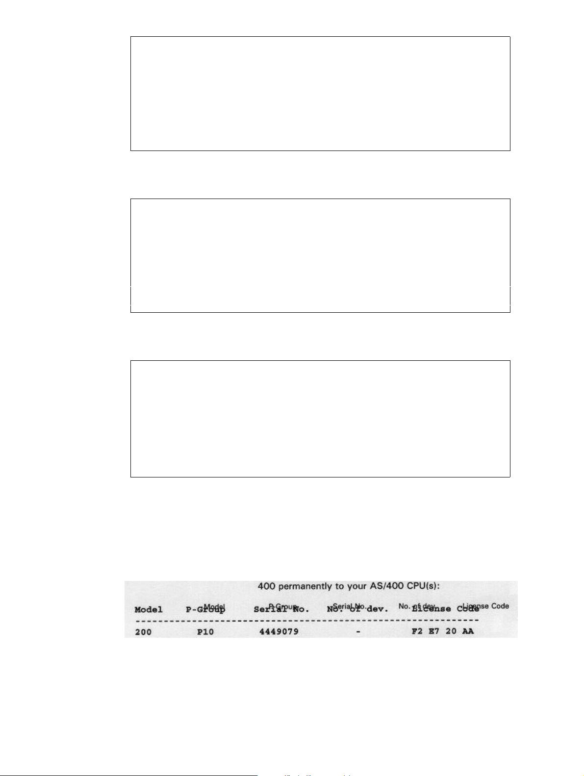
Seqnbr. Type
13,0 9 Remap window Input line _28 - _28 Position _26 - _39
Print: From upper edge 05,060 Line spacing . . _40
From left edge 000004 Ignore blank lines N (Y N)
Adjustment C (U L R C N B E +)
Rotation 000
Font 9902 F4=List
Blank original _ B = blank original version
Condition: Position ___ - ___
Is > = < N _ ______________________________
Blank after _ B = Blank condition after
F3=Exit F4=Prompt F18=DSPSPLF F12=Cancel
We press Enter to save and proceed with column header “No. of dev”. We type 14 to
create a new sequence line followed by Field exit and 9:
Seqnbr. Type
14,0 9 Remap window Input line _28 - _28 Position _40 - _53
Print: From upper edge 05,060 Line spacing . . _40
From left edge 000005 Ignore blank lines N (Y N)
Adjustment C (U L R C N B E +)
Rotation 000
Font 9902 F4=List
Blank original _ B = blank original version
Condition: Position ___ - ___
Is > = < N _ ______________________________
Blank after _ B = Blank condition after
F3=Exit F4=Prompt F18=DSPSPLF F12=Cancel
We press Enter to save and proceed with column header “License Code”. We type 15 to
create a new sequence line followed by Field exit and 9:
Seqnbr. Type
15,0 9 Remap window Input line _28 - _28 Position _54 - _70
Print: From upper edge 05,060 Line spacing . . _40
From left edge 000006 Ignore blank lines N (Y N)
Adjustment C (U L R C N B E +)
Rotation 000
Font 9902 F4=List
Blank original _ B = blank original version
Condition: Position ___ - ___
Is > = < N _ ________________________
Blank after _ B = Blank condition
afterF3=Exit F4=Prompt F18=DSPSPLF F12=Cancel
We press Enter to save sequence line 15.
If you made a test print of the overlay or a PCL view with F14 at this stage you will
discover that both the original text and the remapped text is printed (as illustrated below).
This is just a temporary issue and is dealt with in step 17.
User’s Manual for InterForm400® 89
Page 90

Step 9. Making Equal Distance between Item Line Columns
We now want to perform the same actions for the item-line columns below the dotted line.
As the horizontal positions of the item line columns are identical to the column headers,
we can copy the sequence lines 11 to 15 and just correct the vertical position (from upper
edge) and the input line numbers.
We select F5 for service functions and select 3. Copy definitions into this overlay:
Design InterForm 400 overlay APF300D
Overlay name: MYDEMO Overlay text: Mydemo
Overlay name: MYDEMO Overlay text: Mydemo
Seqnbr. Type Overlay definition
0009 8 Tabulator lin.043-055 pos 08-080 left 4,000C font 9903
0010 8 Tabulator lin.043-055 pos 08-080 left 4,000C font 9903
0011 9 Remap window 28-028 pos 08-014 top 5,060 left 2,000 C
0012 9 Remap window 28-028 pos 15-025 top 5,060 left 3,000 C
0013 9 Remap window 28-028 pos 26-039 top 5,060 left 4,000 C
0014 9 Remap window 28-028 pos 40-053 top 5,060 left 5,000 C
0015 9 Remap window 28-028 pos 54-070 top 5,060 left 6,000 C
In this function you can copy lines into this overlay definition.
Overlay to be copied from . . . . . . . . __________ blank = this overlay
Sequence numbers from/to to be copied . . 0011_ - 0015_
Inserted at sequence number . . . . . . . 16___
F4 = overview overlays
F24 = shift to look at FROM-overlay
We define the copies of line 11 to 15 to be inserted from sequence line 16 and onwards.
By using F18 we find the item lines to range from line 30 and onwards. We estimate the
last possible item line to be in the line just before the lower part of the body text, i.e. line
42:
We enter each sequence line from 16 to 20 and correct the line interval to 30-42, but
leave all other values untouched:
Seqnbr. Type
16,0 9 Remap window Input line _30 - _42 Position __8 - _14
Print: From upper edge 05,060 Line spacing . . _40
From left edge 000002 Ignore blank lines N (Y N)
Adjustment C (U L R C N B E +)
Rotation 000
Font 9902 F4=List
Blank original _ B = blank original version
Condition: Position ___ - ___
Is > = < N _ ______________________________
Blank after _ B = Blank condition after
F3=Exit F4=Prompt F18=DSPSPLF F12=Cancel
90 User’s Manual for InterForm400
®
Page 91

Seqnbr. Type
17,0 9 Remap window Input line _30 - _42 Position _15 - _25
Print: From upper edge 05,060 Line spacing . . _40
From left edge 000003 Ignore blank lines N (Y N)
Adjustment C (U L R C N B E +)
Rotation 000
Font 9902 F4=List
Blank original _ B = blank original version
Condition: Position ___ - ___
Is > = < N _ ______________________________
Blank after _ B = Blank condition after
F3=Exit F4=Prompt F18=DSPSPLF F12=Cancel
Seqnbr. Type
18,0 9 Remap window Input line _30 - _42 Position _26 - _39
Print: From upper edge 05,060 Line spacing . . _40
From left edge 000004 Ignore blank lines N (Y N)
Adjustment C (U L R C N B E +)
Rotation 000
Font 9902 F4=List
Blank original _ B = blank original version
Condition: Position ___ - ___
Is > = < N _ _____________________________
Blank after _ B = Blank condition after
F3=Exit F4=Prompt F18=DSPSPLF F12=Cancel
Seqnbr. Type
19,0 9 Remap window Input line _30 - _42 Position _40 - _53
Print: From upper edge 05,060 Line spacing . . _40
From left edge 000005 Ignore blank lines N (Y N)
Adjustment C (U L R C N B E +)
Rotation 000
Font 9902 F4=List
Blank original _ B = blank original version
Condition: Position ___ - ___
Is > = < N _ ______________________________
Blank after _ B = Blank condition after
F3=Exit F4=Prompt F18=DSPSPLF F12=Cancel
Seqnbr. Type
20,0 9 Remap window Input line _30 - _42 Position _54 - _70
Print: From upper edge 05,060 Line spacing . . _40
From left edge 000006 Ignore blank lines N (Y N)
Adjustment C (U L R C N B E +)
Rotation 000
Font 9902 F4=List
Blank original _ B = blank original version
Condition: Position ___ - ___
Is > = < N _ ______________________________
Blank after _ B = Blank condition after
F3=Exit F4=Prompt F18=DSPSPLF F12=Cancel
The vertical position (from the upper edge) of sequence line 16 to 20 are currently
identical to the column headers in sequence line 11 to 15, but the item columns are
supposed to start 1 line lower than the column headers.
We could now edit each line from 16 to 20 and correct that. However, instead we use the
service function to adjust the vertical positioning of the entire range of lines from 16 to 20:
We press F5 and we select option 1. Move the placement on the page:
User’s Manual for InterForm400® 91
Page 92

Design InterForm 400 overlay APF300D
Overlay name: MYDEMO Overlay text: Mydemo
Seqnbr. Type Overlay definition
0017 9 Remap window 30-042 pos 15-025 top 5,060 left 3,000 C
0018 9 Remap window 30-042 pos 26-039 top 5,060 left 4,000 C
0019 9 Remap window 30-042 pos 40-053 top 5,060 left 5,000 C
0020 9 Remap window 38-042 pos 54-070 top 5,060 left 6,000 C
In this function you can move the overlay up/down or left/rigth on the page.
Line interval to be moved . . . . . . : 0016_ - 0020_
Distance to move:
- to the right +/- _______
- downwards +/- 0,040__
1 line at 6 lpi is 1/6" equaling 40 pels (40/240") meaning our vertical movement should be
0,040. When we press Enter we discover that the top position of the entire range changes
from 5,060 to 5,100.
Step 10. Defining the Column Headers White on Black
Now we would like to make the column headers appear with white text on a black
background.
First we will need to define a black box, which is created as a frame with black filling. It is
very important that the frame is defined in a sequence line before the text in order to place
it as a background for the text.
We therefore insert a line before line 11 which is the remapping of the column header
“Model”.
Insertion between line 10 and 11 is done by typing the sequence line number 10,1
followed by Field Exit:
Design InterForm 400 overlay APF300D
Overlay name: MYDEMO Overlay text: Mydemo
Seqnbr. Type Overlay definition
0009 8 Tabulator lin.043-055 pos 08-080 left 4,000C font 9903
0010 8 Tabulator lin.043-055 pos 08-080 left 4,000C font 9903
0011 9 Remap window 28-028 pos 08-014 top 5,060 left 2,000 C
0012 9 Remap window 28-028 pos 15-025 top 5,060 left 3,000 C
0013 9 Remap window 28-028 pos 26-039 top 5,060 left 4,000 C
0014 9 Remap window 28-028 pos 40-053 top 5,060 left 5,000 C
0015 9 Remap window 28-028 pos 54-070 top 5,060 left 6,000 C
0016 9 Remap window 28-028 pos 08-014 top 5,100 left 2,000 C +
Seqnbr. Type Inch.pel Repetition
10,1 1 Frame Top edge 05,030 Move right _______
Left edge 01,120 Move down _______
Right edge 06,116 Extra times ___
Bottom edge 05,068
Thikness in pels 001 NW NE SW SE
Round/Sharp (R S) S Radius __ __ __ __
Fill pattern 8 F4=List
F3=Exit F18=DSPSPLF F12=Cancel
92 User’s Manual for InterForm400
®
Page 93

We use our ruler to find proper coordinates for our frame (see page ? on how to print a
ruler).
We prepare the values for the edges to match the formatting we will make for the item
lines later. This step usually requires some test printing in order to find the exact values
unless very exact calculations are performed.
We enter 8 as fill pattern for our frame, which is a black pattern (see patterns, page ?).
We press enter and our line is given sequence number 11.
We will now have to change the text color (ink) for the column headers to white. The
sequence lines defining the column headers have now changed to the interval 12 to 16
due to the insertion of the frame.
We insert a change of Ink after the black box and before the first column header (Remap
Windows) by selecting sequence line 11,1:
Design InterForm 400 overlay APF300D
Overlay name: IF400DEMO Overlay text: IF400DEMO
Overlay name: MYDEMO Overlay text: Mydemo
Seqnbr. Type Overlay definition
0009 8 Tabulator lin.043-055 pos 08-080 left 4,000C font 9903
0010 8 Tabulator lin.043-055 pos 08-080 left 4,000C font 9903
0011 1 Frame top 05,030 left 01,120 right 06,116 bottom 05,068
0012 9 Remap window 28-028 pos 08-014 top 5,060 left 2,000 C
0013 9 Remap window 28-028 pos 15-025 top 5,060 left 3,000 C
0014 9 Remap window 28-028 pos 26-039 top 5,060 left 4,000 C
0015 9 Remap window 28-028 pos 40-053 top 5,060 left 5,000 C
0016 9 Remap window 28-028 pos 54-070 top 5,060 left 6,000 C +
Seqnbr. Type
11,1 7 Ink
Select ink for the succeeding lines
Pattern 0 blank = unchanged,
0 = 100% white shading,
1-8 = 1-100% shading, ...
F3=Exit F18=DSPSPLF F12=Cancel
We fill in 0 as pattern press Enter to save our new line 12
In order not to have the rest of the text in the overlay printed in white, we will have to
change the ink back to black after the last column header, which now has sequence
number 17.
We insert a line after line 17 by entering 17,1:
User’s Manual for InterForm400® 93
Page 94

Design InterForm 400 overlay APF300D
Overlay name: MYDEMO Overlay text: Mydemo
Seqnbr. Type Overlay definition
0017 9 Remap window 28-028 pos 54-070 top 5,060 left 6,000 C
0018 9 Remap window 30-042 pos 08-014 top 5,100 left 2,000 C
0019 9 Remap window 30-042 pos 15-025 top 5,100 left 3,000 C
0020 9 Remap window 30-042 pos 26-039 top 5,100 left 4,000 C
0021 9 Remap window 30-042 pos 40-053 top 5,100 left 5,000 C
0022 9 Remap window 30-042 pos 54-070 top 5,100 left 6,000 C
Seqnbr. Type
17,1 7 Ink
Select ink for the succeeding lines
Pattern 8 blank = unchanged,
0 = 100% white shading,
1-8 = 1-100% shading, ...
F3=Exit F18=DSPSPLF F12=Cancel
We enter 8 for 100% shading (Black), which will ensure that the following sequence lines
will be visible. We press Enter to save our new sequence line 18.
Step 11. Defining the Item Line Bars
We would now like to exploit the Repetition and Pattern options in the overlay element
Frame to make shaded horizontal “bars” to provide a better appearance of the item lines.
We place this definition before the first remapping of an item column. The item column
“Model” now has sequence line 19. We therefore enter sequence line 18,1:
Design InterForm 400 overlay APF300D
Overlay name: MYDEMO Overlay text: Mydemo
Seqnbr. Type Overlay definition
0017 9 Remap window 28-028 pos 54-070 top 5,060 left 6,000 C
0018 7 Ink Foreground = BLACK Background = UNALTERED
0019 9 Remap window 30-042 pos 08-014 top 5,100 left 2,000 C
0020 9 Remap window 30-042 pos 15-025 top 5,100 left 3,000 C
0021 9 Remap window 30-042 pos 26-039 top 5,100 left 4,000 C
0022 9 Remap window 30-042 pos 40-053 top 5,100 left 5,000 C
0023 9 Remap window 30-042 pos 54-070 top 5,100 left 6,000 C
Seqnbr. Type Inch.pel Repetition
18,1 1 Frame Top edge 05,110 Move right _______
Left edge 01,120 Move down __0,080
Right edge 06,116 Extra times __5
Bottom edge 05,150
Thikness in pels 000 NW NE SW SE
Round/Sharp (R S) S Radius __ __ __ __
Fill pattern B F4=List
F3=Exit F18=DSPSPLF F12=Cancel
We want the shaded frames to be 1/6" thick with a distance of 1/6” between.
First we must find out where to place the first frame. We want to place our first frame
behind every second item line starting with item line number two. This means 0,175"
(240x0,175 = 42 pels) lower than the black frame. We see that the black frame (sequence
94 User’s Manual for InterForm400
®
Page 95

line 11) ends 5,068 from the top. We add 42 pels to 5,068 and get 5,110.
We state the same values for left and right edge as the black frame, and define the
thicknes of our frame to be 1/6" (40/240") by adding 40 to the top edge.
We do not want a border only a raster filling, and therefore we leave this blank. But we will
have a light shading and we enter the value B which is a light 600dpi pattern.
For the repeated frames we must first state the distance from the top of the first frame to
the top of the next frame. We want to place a frame behind every second item line and as
the frame is 1/6” (40 pels) thick in the vertical direction and we want 1/6” inch between the
frames, we must add these two values. This gives us 40+40 = 80 pels.
We want 6 frames total which means we should repeat the frame 5 extra times.
We press Enter to save our new sequence line 19.
Step 12. Defining the 5 Item Coloumn Frames
We now want to define some frames to divide the item lines columns in the spool entry:
We want to place the definition just after the previous definition of the raster frames, and
we enter 19,1 for inserting an overlay element before sequence line 20:
Design InterForm 400 overlay APF300D
Overlay name: MYDEMO Overlay text: Mydemo
Seqnbr. Type Overlay definition
0017 9 Remap window 28-028 pos 54-070 top 5,060 left 6,000 C
0018 7 Ink Foreground = BLACK Background = UNALTERED
0019 1 Frame top 05,110 left 01,120 right 06,116 bottom 05,150
0020 9 Remap window 30-042 pos 08-014 top 5,100 left 2,000 C
0021 9 Remap window 30-042 pos 15-025 top 5,100 left 3,000 C
0022 9 Remap window 30-042 pos 26-039 top 5,100 left 4,000 C
0023 9 Remap window 30-042 pos 40-053 top 5,100 left 5,000 C
0024 9 Remap window 30-042 pos 54-070 top 5,100 left 6,000 C
Seqnbr. Type Inch.pel Repetition
19,1 1 Frame Top edge 05,072 Move right ______1
Left edge 01,120 Move down _______
Right edge 02,116 Extra times __4
Bottom edge 07,120
Thikness in pels 001 NW NE SW SE
Round/Sharp (R S) S Radius __ __ __ __
Fill pattern _ F4=List
F3=Exit F18=DSPSPLF F12=Cancel
The line should start just below the black frame defined in sequence line 11.
We add 4 pels to the bottom of the black frame and we get 5,072 for the top of the item
line frame.
We set the left edge equal to the black frame (1,120) and we set the right edge 1 inch
higher minus a few pels (1,120-0,004=1,116). This will give a small space between each
column frame.
We measure the bottom edge to be around 7½” (7,120).
As we have precisely 1 inch between each column we can move right 1 inch and repeat 4
times to get 5 identical columns.
User’s Manual for InterForm400® 95
Page 96

We press Enter to save our new sequence line 20.
Step 13. Defining the logo as a water mark
Instead of a signature we want to place the logo as a watermark in the bottom of the
page.
For this we use the logo already used in the top of the overlay, but manipulate it to work
as a watermark. We intend to do the following compared to the original logo (see page
32):
• Reverse it.
• Scale it to double size
• Grayscale it
We define the sequence line for the logo just after the other logo by entering sequence
line 1,1:
Design InterForm 400 overlay APF300D
Overlay name: MYDEMO Overlay text: Mydemo
Seqnbr. Type Overlay definition
0001 I Image DEMOIMAGE Top 01,100 Left 04,180
0002 8 Tabulator lin.003-003 pos 72-072 left12,000L font 0011
0003 9 Remap window 06-011 pos 08-040 top 1,160 left 1,000 L
0004 1 Frame top 01,100 left 00,200 right 04,120 bottom 02,160
0005 9 Remap window 13-013 pos 57-072 top 1,220 left 5,200 C
0006 2 Horizontal top 10,120 left 00,200 right 07,120
0007 5 Text T10,160 L01,200 000° Font9902 Intermate A/S Kongev
0008 8 Tabulator lin.015-015 pos 08-070 left 4,000C font 9907 +
Seqnbr. Type Inch.pel
1,1 I Image From top edge 09,100
From left 02,120
Image name DEMOIMAGE_
Reverse Image R R = Reverse Image
Resolution 150 75,100,150,200,300,600
F3=Exit F4=Prompt F18=DSPSPLF F12=Cancel
We position the logo where a signature would usually be placed, namely in the bottom of
the page.
We select the same image file as used for the top logo.
We state R to reverse the image, and we press Enter to save the corrections to the new
sequence line 2.
The logo is created for printing in 300 dpi, so in order to scale to double size we simply
define the resolution to be 150 dpi, that means we simply get twice as much space
between every dot in the image.
The logo now needs to be dimmed in order to appear as a watermark. For this we change
the ink of the image. This is the same procedure we used for printing the column headers
white on black.
We insert a sequence line just before the image by entering line 1,1, and we select 7 for
Ink:
96 User’s Manual for InterForm400
®
Page 97

Design InterForm 400 overlay APF300D
Overlay name: MYDEMO Overlay text: Mydemo
Seqnbr. Type Overlay definition
0001 I Image DEMOIMAGE Top 01,100 Left 04,180
0002 I Image DEMOIMAGE Top 09,100 Left 02,120
0003 8 Tabulator lin.003-003 pos 72-072 left12,000L font 0011
0004 9 Remap window 06-011 pos 08-040 top 1,160 left 1,000 L
0005 1 Frame top 01,100 left 00,200 right 04,120 bottom 02,160
0006 9 Remap window 13-013 pos 57-072 top 1,220 left 5,200 C
0007 2 Horizontal top 10,120 left 00,200 right 07,120
0008 5 Text T10,160 L01,200 000° Font9902 Intermate A/S Kong +
Seqnbr. Type
1,1 7 Ink
Select ink for the succeeding lines
Pattern C blank = unchanged,
0 = 100% white shading,
1-8 = 1-100% shading, ...
F3=Exit F4=Prompt F18=DSPSPLF F12=Cancel
We select C for pattern which is a medium shading.
We press Enter to save the new line 2.
As usual we will need to set the Ink back to default just after the logo.
we enter 3,1 and select 7 for Ink:
Design InterForm 400 overlay APF300D
Overlay name: MYDEMO Overlay text: Mydemo
Seqnbr. Type Overlay definition
0001 I Image DEMOIMAGE Top 01,100 Left 04,180
0002 7 Ink Foreground = Background = UNALTERED
0003 I Image DEMOIMAGE Top 09,100 Left 02,120
0004 8 Tabulator lin.003-003 pos 72-072 left12,000L font 0011
0005 9 Remap window 06-011 pos 08-040 top 1,160 left 1,000 L
0006 1 Frame top 01,100 left 00,200 right 04,120 bottom 02,160
0007 9 Remap window 13-013 pos 57-072 top 1,220 left 5,200 C
0008 2 Horizontal top 10,120 left 00,200 right 07,120 +
Seqnbr. Type
3,1 7 Ink
Select ink for the succeeding lines
Pattern 8 blank = unchanged,
0 = 100% white shading,
1-8 = 1-100% shading, ...
F3=Exit F4=Prompt F18=DSPSPLF F12=Cancel
We enter 8 for 100% shading (Black) and we press Enter to save our new line 4.
User’s Manual for InterForm400® 97
Page 98

Step 14. Defining the Copy Management
We will now add the text COPY on “page two" copies only. To do this we will first have to
enable and configure the copy management.
We press F12 to exit to the global settings.
Design InterForm 400 overlay APF300D
Overlay name IF400DEMO
Overlay text _____________________________
Line spacing 040___ in 1/240 of an inch (*INPUT, 1-720)
Rotation 000___ (*INPUT, 0, 90, 180, 270)
Extra left margin
positions _0 (0-99)
Maximum number of
print positions 378 (1-378)
Extra blank lines
on top _0 (0-99)
Font 0066_ *INPUT, fontnumber F4=List
Extended page def. N (Y N)
Drawer *PRINTER (*INPUT, *PRINTER 1-9, 20-39)
Paper Size 0 F4=List
Pages per side __
Copy management Y (Y N)
Duplex print N (N=no S=short edge margin L=long edge margin)
Duplex margin __0 in 1/240 of an inch (1-720)
Back page overlay __________ Code for placement _ (B=back page F=front)
F3=Exit F4=Prompt F11=Delete this overlay F12=Cancel
F13=Set view/print parameters F14=PCL-view
We state Y for Copy Management in order to be able to let our overlay control the
number of copies and the overlay elements which should be used on each copy. (refer to
page 46)
By pressing enter we get the screen for definition of Copy Management:
Design InterForm 400 overlay APF300D
Overlay name: MYDEMO Overlay text: Mydemo overlay
Number of copies of each page
Primary set . . . . . . . 2_________ *VAR, 1-9
Secondary set . . . . . . 1_________ *VAR. 1-9
F3=Exit F12=Cancel
Here we fill in 2 copies for the Primary Set which means we would like two pages
generated from each page in the source spool entry. Note that the number of copies
entered here include the original. (refer to page 46 For detailed info on Primary Set)
We will not use the Secondary set so we just enter 1. (refer to page 46)
We now press Enter to fill in the drawers.
98 User’s Manual for InterForm400
®
Page 99

Copy Primary Secondary
1 ________1 ________1 Valid drawers
2 ________4 1-255
valid paper types:
F4=List
Do you want stapling . . Y/N N
F3=Exit F12=Cancel
F13=Set view/print parameters F14=PCL-view F18=DSPSPLF F19=DSPPFM
We define that the originals (copy one) should be taken from drawer 1, and copies from
drawer 2 (Note that we are inserting the PCL value “4" as the second drawer. Refer to
page 376 for more information on how to select drawers). We can later in the design
window specify for each forms element (boxes, lines, images etc.) if it should be used for
the original, the copy or both. (see Copy Management page 53)
We will not use the secondary set in this exercise so we just fill in 1 in the remaining field.
We will not use stapling in this exercise, so we fill in N in this field.
When we press Enter we re-enter the design window.
Step 15. Defining the COPY Symbol as Watermark
The intention of the copy sign is to place this information as a watermark in the address
field. We can therefore place the definition between the two Ink changes we made for the
logo watermark, and thereby exploit the same raster pattern definition.
We create a new sequence line 3,1 between the two Ink changes :
Design InterForm 400 overlay APF300D
Overlay name: MYDEMO Overlay text: Mydemo
Seqnbr. Type Overlay definition
0001 I Image DEMOIMAGE Top 01,100 Left 04,180
0002 7 Ink Foreground = Background = UNALTERED
0003 I Image DEMOIMAGE Top 09,100 Left 02,040
0004 7 Ink Foreground = BLACK Background = UNALTERED
0005 8 Tabulator lin.003-003 pos 72-072 left12,000L font 0011
0006 9 Remap window 06-011 pos 08-040 top 1,160 left 1,000 L
0007 1 Frame top 01,100 left 00,200 right 04,120 bottom 02,160
0008 9 Remap window 13-013 pos 57-072 top 1,220 left 5,200 C +
Seqnbr. Type Copy management
3,1 _ 1 = Frame 2 = Horizontal From To
3 = Vertical 4 = Line Primary 2 2
5 = Text 6 = Page number Secondary _ _
7 = Ink 8 = Tabulator
9 = Remap window I = Image
? = If .. then F = PCL-file
G = HP-GL/2 file S = Sub-overlay
* = Comment
F3=Exit F12=Cancel
F13=Set view/print parameters F14=PCL-view F18=DSPSPLF F19=DSPPFM
Before we enter a type we remember that this forms element should only be activated on
the copy which means we will have to fill in Copy Management. By entering values for
Primary set and not for Secondary set, we define that our copy management definitions
apply to the Primary set only (see Copy management page 53)
User’s Manual for InterForm400® 99
Page 100

We now proceed by entering type 5 for Text:
Seqnbr. Type Inch.pel
3,1 5 Text constant From top edge _2,120
From left _1,120
Rotation 000
Font 7001 F4=List
Text COPY_______________________________
______________________________________________________________________________
_____________________________
F3=Exit F4=Prompt F12=Cancel
We place the text approximately in the middle of the address field. If you want to tilt the
copy watermark you can define a rotation of 030, 120, 210 or 300 degrees.
For the font out line we can prompt the font list with F4. The largest font currently
assigned to the system is font ID 2103 with point size 24 (see font list on page 383).
We can now choose to use this font, or we can assign a new font ID a larger font.
If you feel comfortable enough with InterForm400® by now, you should try to assign the
large font, Go to 80. Administration Menu (either in this session by exiting with F3, or by
using another session). Go to section 7. Work with fonts and select 1.Description of
additional fonts. Now perform the steps described in the Example of defining a
resident Printer Font on page 281).
Afterwards we re-enter sequence line 4 in our overlay MYDEMO.
If you have chosen for now to use the existing 24 point font you should enter font ID 2103.
If you used the example on page 281 to create a 70 point font, you should enter font ID
7001.
The text is of course COPY.
We press Enter to save sequence line 4.
100 User’s Manual for InterForm400
®
 Loading...