

Page 1
Operation Manual
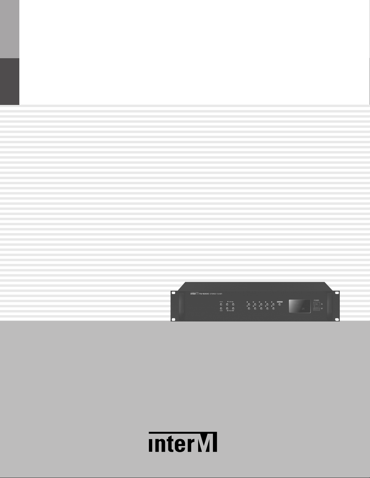
Stereo Tuner
TU-6200
*Rack mount products in the Western Hemisphere (North America, South America, and the Caribbean)
do not have handles installed due to customer preference.
Page 2
STEREO TUNER
Welcome
Welcome
A personal welcome to you from the management and employees of Inter-M
All of the co-workers here at Inter-M are dedicated to providing excellent products with inherently good value,
and we are delighted you have purchased one of our products.
We sincerely trust this product will provide years of satisfactory service, but if anything is not to your complete
satisfaction, we will endeavor to make things right.
Welcome to Inter-M, and thank you for becoming part of our worldwide extended family!
This symbol is int ended to ale rt the user to the
CAutION
RISK OF ELECTRIC SHOCK
DO NOT OPEN
CAUTION: TO REDUCE THE RISK OF ELECTRIC SHOCK.
DO NOT REMOVE COVER (OR BACK).
NO USER-SERVICEABLE PARTS INSIDE.
REFER SERVICING TO QUALIFIED SERVICE PERSONNEL.
Caution: To prevent electric shock do not use this (polarized) plug with
Attentions: Pour prévenir les chocs électriques ne pas utiliser cette
WARNING
To prevent fire or shock hazard, do not
expose the unit to rain or moisture.
*WARNING FOR YOUR PROTECTION PLEASE READ THE FOLLOWING-WATER AND MOISTURE: Unit should not be used near water(e.g.
near a bathtub, washbowl, kitchen sink, laundry tub, in a wet basement, or near a swimming pool, etc). Care should be taken so than objects do
not fall and liquids are not spilled into the enclosure through openings.
*CLASS 2 WIRING (Adjacent to speaker terminal): The speaker output of this apparatus can exceed 10 Watts and could be a shock injury.
Connection to speakers should be performed by a skilled person.
*Do not install this equipment in a confined space such as a book case or similar unit.
*This apparatus shall not be exposed to dripping or splashing and no objects filled with liquids, such vases, shall be placed on the apparatus.
*This apparatus shall be connected to a mains socket outlet with a protective earthing connection.
It has heed to be easy to disconnect the device. To disconnect the device from power, separate AC input cable from inlet or unplug the AC Cord.
*
CAutION
*These servicing instructions are for use by qualified service personnel only. To reduce the risk of electric shock, do not perform any servicing
other than that contained in the operating instructions unless you are qualified to do so.
NOtE
*This equipment has been tested and found to comply with the limits for a Class A digital device, pursuant to Part 15 of the FCC Rules. These limits are
designed to provide reasonable protection against harmful interference when the equipment is operated in a commercial environment. This equipment
generates, uses, and can radiate radio frequency energy and, if not installed and used in accordance with the instruction manual, may cause harmful
interference to radio communications. Operation of this equipment in a residential area is likely to cause harmful interference in which case the user will
be required to correct the interference at his own expense.
presence of uninsulated “dangerous voltage” within
the product’s enclosur e that ma y be of sufficient
magnitude to constitute a risk of electric shock to
persons.
This symbol is int ended to ale rt the user to the
presence of important operation and maintenance
(servicing) instructions in the literature accompanying
the appliance.
an extension cord, receptacle or other outlet unless the blades
can be fully inserted to prevent blade exposure.
fiche polarisée avec un prolongateur, une prise de courant
on une autre sortie de courant, sauf si les lames peuvent
étre inséré es à fond sans en lai sser aucune par tie à
découvert.
Page 3

STEREO TUNER
Contents
Contents
Unpacking .......................................................................................................................................2
Installation
Environment....................................................................................................................................2
Important Safety Instructions.............................................................................................................2
Features............................................................................................................................................3
Additional Explanations................................................................................................................3
Front Panel ......................................................................................................................................4
Rear Panel .......................................................................................................................................5
Operation Method..........................................................................................................................6
Connecting Antenna .....................................................................................................................7
Block Diagram ................................................................................................................................8
Specifications ..................................................................................................................................9
Service............................................................................................................................................11
Variations and Options ...............................................................................................................11
Warranty .......................................................................................................................................11
TU-6200
1
Page 4

STEREO TUNER
Unpacking
Unpacking
Although your TU-6200 is neither complicated nor difficult to operate, we recommend you take a few minutes
to read this brief manual and familiarize yourself with the important information regarding product features,
setup and operation.
As with most electronic devices, we strongly recommend you to retain the original packaging. In the unlikely
event the product must be returned for servicing, the original packaging (or reasonable equivalent) is required.
Installation
Installation
Environment
Never place this product in an environment which could alter its performance or reduce its service life. Such
environments usually include high levels of heat, dust, moisture, and vibration.
IMPORTANT SAFETY INSTRUCTIONS
1. Read these instructions.
2. Keep these instructions.
3. Heed all warnings.
4. Follow all instructions.
5. Do not use this apparatus near water.
6. Clean only with dry cloth.
7. Do not block any ventilation openings. Install in accordance with the manufacturer’s instructions.
8. Do not install near any heat sources such as radiators, heat registers, stoves, or other apparatus (including
amplifiers) that produce heat.
9. Do not defeat the safety purpose of the polarized or grounding-type plug. A polarized plug has two blades
with one wider than the other. A grounding type plug has two blades and a third grounding prong. The wide
blade or the third prong are provided for your safety. If the provided plug does not fit into your outlet, consult
an electrician for replacement of the obsolete outlet.
10. Protect the power cord from being walked on or pinched particularly at plugs, convenience receptacles, and
the point where they exit from the apparatus.
11. Only use attachments/accessories specified by the manufacturer.
12. Use only with the cart, stand, tripod, bracket, or table specified by the manufacturer, or sold with the apparatus.
When a cart is used, use caution when moving the cart/apparatus combination to avoid injury from tip-over.
13. Unplug this apparatus during lightning storms or when unused for long periods of time.
14. Refer all servicing to qualified service personnel. Servicing is required when the apparatus has been
damaged in any way, such as power-supply cord or plug is damaged, liquid has
been spilled or objects have fallen into the apparatus, the apparatus has been
exposed to rain or moisture, does not operate normally, or has been dropped.
2
S3125A
TU-6200
Page 5
Features
1
2345
6
789
Features
- Memory of 40 FM/AM frequencies
40 broadcasting frequencies can be memorized.
- Auto Scan
Broadcast station can be selected automatically with automatic seek function.
- AMX, CRESTRON INTERFACE
It supports the control port to integrate with the remote control device such as AMX and CRESTRON control
systems for the user assignments.
STEREO TUNER
Additional Explanations
Additional Explanations
- AMX, CRESTRON INTERFACE
It is the terminal which is connected with remote controllers like AMX and CRESTRON control systems.
PINOUT and controllable operations are as follows.
(Max. cable length is about 15M)
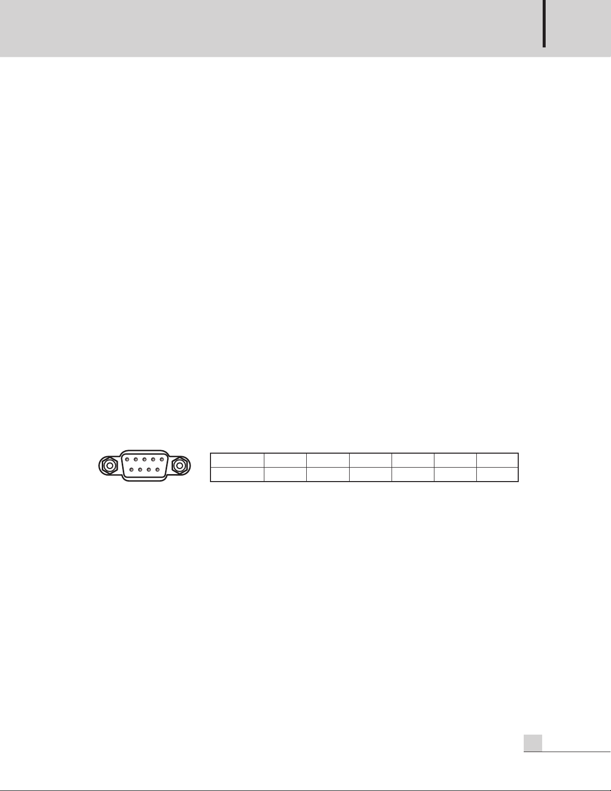
1. RS-232 PINOUT Specification
Pin 123456~9
Purpose Not Used Receiver Transmit Not Used Ground Not Used
2. Controllable functions: POWER ON/OFF, BAND, TUNING DOWN/UP, PRESET DOWN/UP, 10KEY
3. Downloading control protocols
You can download it via www.inter-m.com.
TU-6200
3
Page 6

STEREO TUNER
1 4 5 7862 3
Front Panel
Front Panel
1. MODE BUTTON
It is used when selecting FM broadcast mode (MONO/STEREO).
2. AM/FM BUTTON
It is used when selecting AM and FM broadcasting.
3. ▼/▲(FREQUENCY DOWN/UP) BUTTON
It is used when changing the frequency.
4. ◀◀/▶▶(PRESET DOWN/UP) BUTTON
It is used when selecting the memorized broadcast frequency.
5. 0~9 NUMBER BUTTONS
It is used when memorizes the broadcast frequency or selects the memorized frequency.
6. MEMORY BUTTON
It is used when memorizing the broadcast frequency.
7. DISPLAY WINDOW
It is the window displaying the system information.
8. POWER BUTTON
It is the button for the power ON/OFF.
4
TU-6200
Page 7

Rear Panel
1 4 5 62 3
Rear Panel
STEREO TUNER
1. AC INPUT TERMINAL
It is the terminal witch connects the power cord.
2. RS-232 INTERFACE
It is the terminal which connects the remote controller such as AMX and CRESTRON control systems.
3. R-CHANNEL XLR OUTPUT
It is R-channel balance audio output terminal.
4. L-CHANNEL XLR OUTPUT
It is L-channel balance audio output terminal.
5. RCA OUTPUT TERMINAL
It is L/R 2 channels unbalance audio output terminal.
6. ANTENNA TERMINAL
It is the terminal which connects FM/AM antenna.
TU-6200
5
Page 8

STEREO TUNER
Operation Method
Operation Method
1. SELECT BROADCAST FREQUENCY AUTOMATICALLY AND MANUALLY
1) Push the power switch on the front panel.
2) By using ▼/▲ (frequency DOWN/UP) button, select the frequency you desire.
- Automatic Seeking: push the frequency down or up button for 2 seconds, it will stop at the receivable
frequency.
- Manual Seeking: push the frequency down or up button shortly to select the broadcast frequency.
2. MODE(MONO/STEREO) BUTTON
1) If noise is mixed in FM broadcast, push this button, then it will be converted to mono so that you can hear
more clear broadcast sound.
3. HOW TO SAVE BROADCAST FREQUENCY AND LOAD IT
1) With ▼/▲ (Frequency DOWN/UP) button, select the frequency you desire.
2) Push MEMORY button, then MEMORY will be displayed on the window for 10 seconds.
3) With number button (0~9) to select the channel number to be saved.
4) Repeat number 1 to 3, then max 40 frequencies can be memorized.
5) Broadcast frequency saved in each channel can be selected with number button or ◀◀/▶▶ (PRESET
DOWN/UP) button.
4. TURN ON/OFF BUZZER SOUND
1) It is the function which turns on/off buzzer (Beep~) generated whenever pushing the button.
2) Push MEMORY and MODE buttons same time, then “SET MODE” will be displayed on the window.
3) Push ◀◀/▶▶(PRESET DOWN/UP) button to display the current status of BUZZER ON/OFF.
4) Select ON/OFF by using ▼/▲(Frequency DOWN/UP) button. (Default setting is ON)
5) Select either ON or OFF, then push MEMORY button to complete the setting.
6
TU-6200
Page 9

Connecting Antenna
Connecting Antenna
1. FM ANTENNA
Due to its property, FM broadcast frequency will be weaker in valley, surroundings of building, reinforced
building, etc. install the antenna by considering frequency strength or surrounding situations.
2. INSTALLATION OF FM ANTENNA
Connect to FM antenna terminal as shown in the below figure, and decide the installation position and
direction to make reception good while listening the broadcast. Noise may occur in the downtown area and
a section of a city, industrial complex where traffic is heavy and near power line even if FM exclusive
antenna is used. Use coaxial cable of 75Ω.
STEREO TUNER
3. AM LOOP ANTENA
Connect to AM antenna as shown in the figure, then move the antenna and set to make reception good. If
broadcast is not received well, connect AM FLEM antennal (Vinyl coated line) to the antenna terminal.
4. AM LEAD ANTENA
Make 6~8m of vinyl coated line of single phase, then fix one side to AM terminal and other side to higher
location like wall, etc.
5. AM EXTERNAL ANTENNA
If broadcast is not received well even if lead antenna is installed in the room, install the vinyl coated line in
the outside.
TU-6200
7
Page 10

STEREO TUNER
Block Diagram
Block Diagram
8
TU-6200
Page 11

Specifications
Specifications
TU-6200
FM (22.5kHz MOD. 1kHz)
Tuning range 87.5~108.0MHz
Sensitivity 2uV(Less than 10uV)
T.H.D. (Mono) 0.2% (Less than 0.5%)
S/N (mono) 60dB (Better than 50dB)
Output level (75kHz MOD.) 0dB±3 dB
AM (30% MOD 400Hz)
Tuning range Europe: 522~1629kHz, U.S.A: 520~1710kHz
Sensitivity 18uV(Less than 58uV)
S/N 50dB(Better than 40dB)
T.H.D. 1% (Less than 2%)
Output level -10dB±3 dB
Operation Temperature -10℃ ~ +40℃
STEREO TUNER
Power source
Power consumption 10W
Weight (SET) 4.2kg/9.3lb
Dimensions (SET) 482(W)×88(H)×280(D)mm/19(W)x3.5(H)x11(D)in
* Specifications and design subject to change without notice.
(Supplied AC mains transformer depends on country requirements)
100–120VAC or 220–240VAC; 50/60Hz
TU-6200
9
Page 12

STEREO TUNER
4
40
482
88
280
※ DIMENSIONS
10
TU-6200
Page 13

STEREO TUNER
Service
Service
Procedures
Take steps to insure the problem is not related to operator error or other products within the system. Information
provided in the troubleshooting portion of this manual may help with this process. Once it is certain that the
problem is related to the product contact your warranty provider as described in the warranty section of this
manual.
Schematic
A Schematic is available by contacting your warranty provider.
Parts List
A Parts List is available by contacting your warranty provider.
Variations and Options
Variations and Options
Variations
Variations of this product exist to reflect the variations in AC power requirements throughout the world. Product
supplied through local sources are compatible with local AC power requirements.
Options
No optional items are available for this product.
Warranty
Warranty
Warranty terms and conditions vary by country and may not be the same for all products. Terms and conditions
of warranty for a given product may be determined first by locating the appropriate country which the product
was purchased in, then by locating the product type.
To obtain specific warranty information and available service locations, contact Inter-M directly or the
authorized Inter-M Distributor for your specific country or region.
TU-6200
11
Page 14

NOTE
Page 15

NOTE
Page 16

Inter-M, Ltd. (Korea) began operations in 1983.
Since then, Inter-M has grown to become one of the largest manufacturers
of professional audio and commercial sound electronics equipment in the world.
Inter-M has gained worldwide recognition for its own branded products,
as well as private label manufacturing of electronics sold under other names (OEM).
The company is no longer just a Korean company, but rather a global company
that is truly international in scope, with factories and offices in Korea and China,
and sales and marketing operations located in Japan, Europe, and the U.S.A.
With more than 850 employees around the globe,
Inter-M is well-poised for further growth and expansion.
Inter-M Americas, Inc.
13875 Artesia Blvd. Cerritos, CA 90703 USA
TEL : +1-562-921-0313, FAX : +1-562-921-0370
Home Page : http://www.inter-m.net, E-mail : info@inter-m.net
Inter-M Corporation
Seoul OFFICE:653-5 BANGHAK-DONG, DOBONG-KU, SEOUL, KOREA
TEL : +82-2-2289-8140~8, FAX : +82-2-2289-8149
Home Page : http://www.inter-m.com, E-mail : overseas@inter-m.com
MADE IN KOREA
June 2012
 Loading...