

Page 1
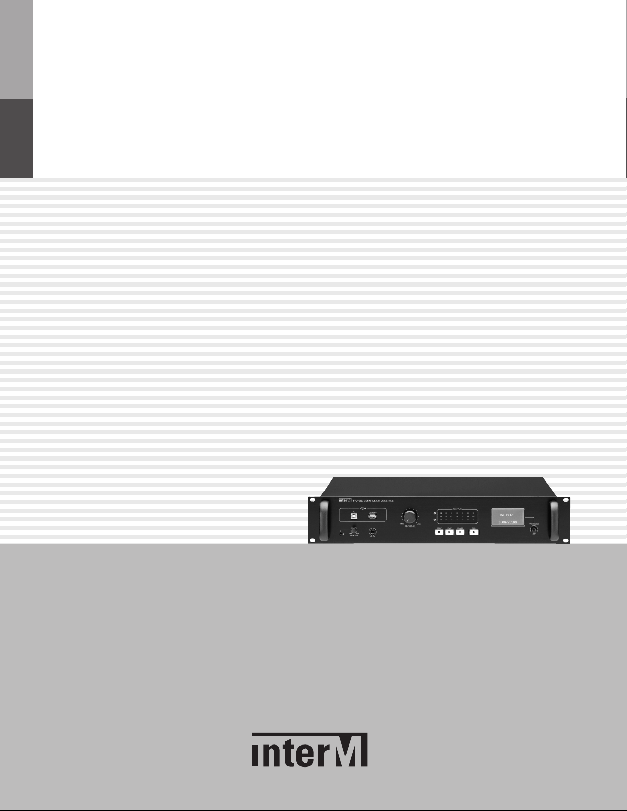
Operation Manual
Multi Voice File
PV-6232A
* Rack mount products in the Western Hemisphere(North America, South America,
and the Caribbean) do not have handles installed due to customer preference.
Page 2
MULTI VOICE FILE
Welcome
Welcome
A personal welcome to you from the management and employees of Inter-M
All of the co-workers here at Inter-M are dedicated to providing excellent products with inherently good value,
and we are delighted you have purchased one of our products.
We sincerely trust this product will provide years of satisfactory service, but if anything is not to your complete
satisfaction, we will endeavor to make things right.
Welcome to Inter-M, and thank you for becoming part of our worldwide extended family!
This s ym bol is intende d to a lert the user to t he
resence of uninsulated “dangerous voltage” within
CAUTION
RISK OF ELECTRIC SHOCK
DO NOT OPEN
p
the product’s e nclosur e that may be of suff icient
agnitude to constitute a risk of electric shock to
m
persons.
CAUTION: TO REDUCE THE RISK OF ELECTRIC SHOCK.
REFER SERVICING TO QUALIFIED SERVICE PERSONNEL.
O NOT REMOVE COVER (OR BACK).
D
NO USER-SERVICEABLE PARTS INSIDE.
TTENTION : RISQUE DE CHOC ELECTRIQUE
A
NE PAS QUVRIR
Caution: To prevent electric shock do not use this (polarized) plug with
Attentions: Pour prévenir les chocs électriques ne pas utiliser cette
WARNING
To prevent fire or shock hazard, do not
expose the unit to rain or moisture.
*WARNING FOR YOUR PROTECTION PLEASE READ THE FOLLOWING-WATER AND MOISTURE: Unit should not be used near water(e.g.
near a bathtub, washbowl, kitchen sink, laundry tub, in a wet basement, or near a swimming pool, etc). Care should be taken so than objects do
not fall and liquids are not spilled into the enclosure through openings.
*Do not install this equipment in a confined space such as a book case or similar unit.
*Warning : To reduce the risk of fire or electric shock, do not expose this apparatus to rain or moisture and objects filled with liquids, such as vases,
should not be placed on this apparatus.
*This apparatus shall be connected to a mains socket outlet with a protective earthing connection.
To completely disconnect this apparatus from the AC mains, disconnect the power supply cord plug from the AC receptacle.
*
*
The mains plug of the power supply cord shall remain readily accessible.
CAUTION
*These servicing instructions are for use by qualified service personnel only. To reduce the risk of electric shock, do not perform any servicing
other than that contained in the operating instructions unless you are qualified to do so.
NOTE
*This equipment has been tested and found to comply with the limits for a Class A digital device, pursuant to Part 15 of the FCC Rules. These limits are
designed to provide reasonable protection against harmful interference when the equipment is operated in a commercial environment. This equipment
generates, uses, and can radiate radio frequency energy and, if not installed and used in accordance with the instruction manual, may cause harmful
interference to radio communications. Operation of this equipment in a residential area is likely to cause harmful interference in which case the user will
be required to correct the interference at his own expense.
This s ym bol is intende d to a lert the user to t he
presence of important operation and maintenance
(servicing) instructions in the literature accompanying
the appliance.
an exten sion cord, rece ptacl e or other outlet unless the
blades can be fully inserted to prevent blade exposure.
fiche polarisée avec un prolongateur, une prise de courant
on une autre sortie de courant, sauf si les lames peuvent
étre ins ér ées à fond sans e n la isser auc un e pa rtie à
découvert.
Pour decon ne ct er c omplete me nt l ’a ppareil du rese au
d’alimentation. deconnecter le cordon d’alimentation de la
prise murale.
La prise du reseau d’alimentation doit demeurer aisement
accessible.
Page 3

MULTI VOICE FILE
Contents
Contents
Unpacking .......................................................................................................................................2
Installation
Environment....................................................................................................................................2
Important Safety Instructions.............................................................................................................2
Features ...........................................................................................................................................3
Package and accessory includes.................................................................................................3
Front Panel ......................................................................................................................................4
Rear Panel .......................................................................................................................................6
How to Operate..............................................................................................................................8
Application ....................................................................................................................................15
PC and RS-232C Connection......................................................................................................16
Block Diagram ..............................................................................................................................17
Specifications ................................................................................................................................18
Service
Procedures....................................................................................................................................20
Schematic.....................................................................................................................................20
Parts List .......................................................................................................................................20
Variations and Options...............................................................................................................20
Warranty .......................................................................................................................................20
PV-6232A
1
Page 4

MULTI VOICE FILE
Unpacking
Unpacking
Although your PV-6232A is neither complicated nor difficult to operate, we recommend you take a few minutes
to read this brief manual and familiarize yourself with the important information regarding product features,
setup and operation.
As with most electronic devices, we strongly recommend you retain the original packaging. In the unlikely event
the product must be returned for servicing, the original packaging (or reasonable equivalent) is required.
Installation
Installation
Environment
Never place this product in an environment which could alter its performance or reduce its service life. Such
environments usually include high levels of heat, dust, moisture, and vibration.
IMPORTANT SAFETY INSTRUCTIONS
1. Read these instructions.
2. Keep these instructions.
3. Heed all warnings.
4. Follow all instructions.
5. Do not use this apparatus near water.
6. Clean only with dry cloth.
7. Do not block any ventilation openings. Install in accordance with the manufacturer’s instructions.
8. Do not install near any heat sources such as radiators, heat registers, stoves, or other apparatus (including
amplifiers) that produce heat.
9. Do not defeat the safety purpose of the polarized or grounding-type plug. A polarized plug has two blades
with one wider than the other. A grounding type plug has two blades and a third grounding prong. The wide
blade or the third prong are provided for your safety. If the provided plug does not fit into your outlet, consult
an electrician for replacement of the obsolete outlet.
10. Protect the power cord from being walked on or pinched particularly at plugs, convenience receptacles, and
the point where they exit from the apparatus.
11. Only use attachments/accessories specified by the manufacturer.
12. Use only with the cart, stand, tripod, bracket, or table specified by the manufacturer, or sold with the apparatus.
When a cart is used, use caution when moving the cart/apparatus combination to avoid injury from tip-over.
13. Unplug this apparatus during lightning storms or when unused for long periods of time.
14. Refer all servicing to qualified service personnel. Servicing is required when the
apparatus has been damaged in any way, such as power-supply cord or plug is
damaged, liquid has been spilled or objects have fallen into the apparatus, the
apparatus has been exposed to rain or moisture, does not operate normally, or has
been dropped.
S3125A
PV-6232A
2
Page 5

Features
Features
- PLAY
You can play various formats of sound source files.
(The playback of MP3, FLAC, OGG, WAV files is supported)
- RECORDING
Saves analogue audio signal to storage media as digital sound source file (MP3).
(Saved as 128kbps/44.1kHz)
- STORAGE CAPACITY
Enables the recording at outside for a long time with mounted 8GB SD Card. Can be extended by up to
32GB.
- INTERFACE WITH PC USING USB TERMINAL
Enables the connection with PC via USB terminal to upload/download sound source files from/into SD Card
at back side.
MULTI VOICE FILE
- DISPLAY ADOPTION
Adoption of 128X64 graphic LCD enables to display a variety of functions.
- MULTIPLE AUDIO INPUT
With input terminals of CD, AUX, and MIC to the front side and the backside, you can record multiple audio
input.
- VOLUME AND OUTPUT LEVEL METER
Output level can be controlled by the volume in front, and it indicates the values of playback level of sound
source file or recording level as dB.
Package and accessory includes
Package and accessory includes
1. AC power cord x 1
2. B-type USB cable x 1
3. Screw for rack mounting x 4
4. User manual x 1
PV-6232A
3
Page 6
MULTI VOICE FILE
MULTI VOICE FILE
P
V
6232A
PC
MEMORY
STOP PLAYPAUSE REC
PARAM ETE R
MIN MAX
MONITOR
M
IC IN
REC / PLAY
M
IN MAX
REC LEVEL
1 5 6 11 12 13
2 7 8 9 103 4
밸런스드 케이블
Ground
MIC IN
Cold
Hot
언밸런스드 케이블
Ground
MIC IN
Hot
Front Panel
Front Panel
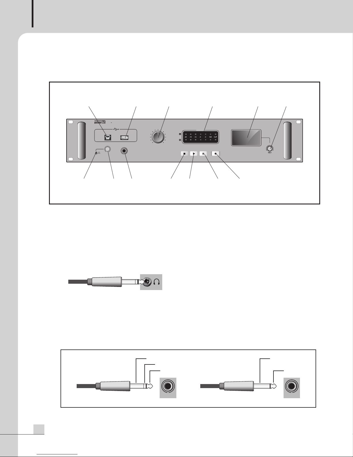
1. PC CONNECTION TERMINAL
It is a terminal to move, delete, and copy sound source files from PC into SD CARD by connecting the USB
cable. During connecting with PC via USB cable, all buttons of equipment will not operate and if you want
to use the functions of playing, recording, and deletion, remove the cable connected to PC before the use.
2. HEADPHONE OUTPUT TERMINAL
It is a terminal to monitor the audio output with headphone connected. Refer to the following for the cables
needed to the terminal.
3. HEADPHONE OUTPUT VOLUME
It is a volume to adjust the audio output level of headphone terminal.
4. MIC IN TERMINAL
It is an input terminal to connect the MIC. Refer to the below figure when using the unbalanced cable for
the balanced cable.
Phone Jack
4
PV-6232A
Balanced cable Unbalanced cable
Page 7

MULTI VOICE FILE
5. USB MEMORY CONNECTION TERMINAL
It is a terminal to connect the USB memory. When connecting the USB memory, you can play or remove
the sound sources in USB memory. When you need to play the files saved to SD CARD in backside,
emove the connected USB memory before use.
r
⇒ Play supported format: MP3
⇒ File system: FAT 32 (NTFS unsupported)
6. RECORDING LEVEL VOLUME
It is a volume to adjust the input level when using the recording function.
7. STOP BUTTON ( )
It is a button to be used when stopping the recording or play. Refer to the instruction of operating method
for details.
8. PLAY ( ▶ )
It is a button to be used when playing the sound source file. Refer to the instruction of operating method
for details.
||
9. PAUSE BUTTON (
It is a button to be used when pausing the play of sound source file. Refer to the instruction of operating
method for details.
10. REC BUTTON ( )
It is a button to be used when recording the audio signal input with MIC IN terminal in front side and
audio input terminal in backside (RCA, AUX). Refer to the instruction of operating method for details.
11. OUTPUT LEVEL METER
Output level is displayed with the division of L (Left) and R (Right). When recording, recording level value
and play level value of sound source file are displayed as dB.
12. DISPLAY WINDOW
It is a window to display the information of multiple operations of equipment.
13. PARAMETER
It is used when selecting the information displaying to the current display window. Refer to the instruction
of operating method for details.
)
PV-6232A
5
Page 8
MULTI VOICE FILE
ACCESS
RS-232C
R
L
SD MEMORY
AC INPUT
2
50mA
CD
LEVEL
LEVEL
AUX
INPUT
OUTPUT
R L
1 2 3 7
5 6 884
Rear Panel
Rear Panel
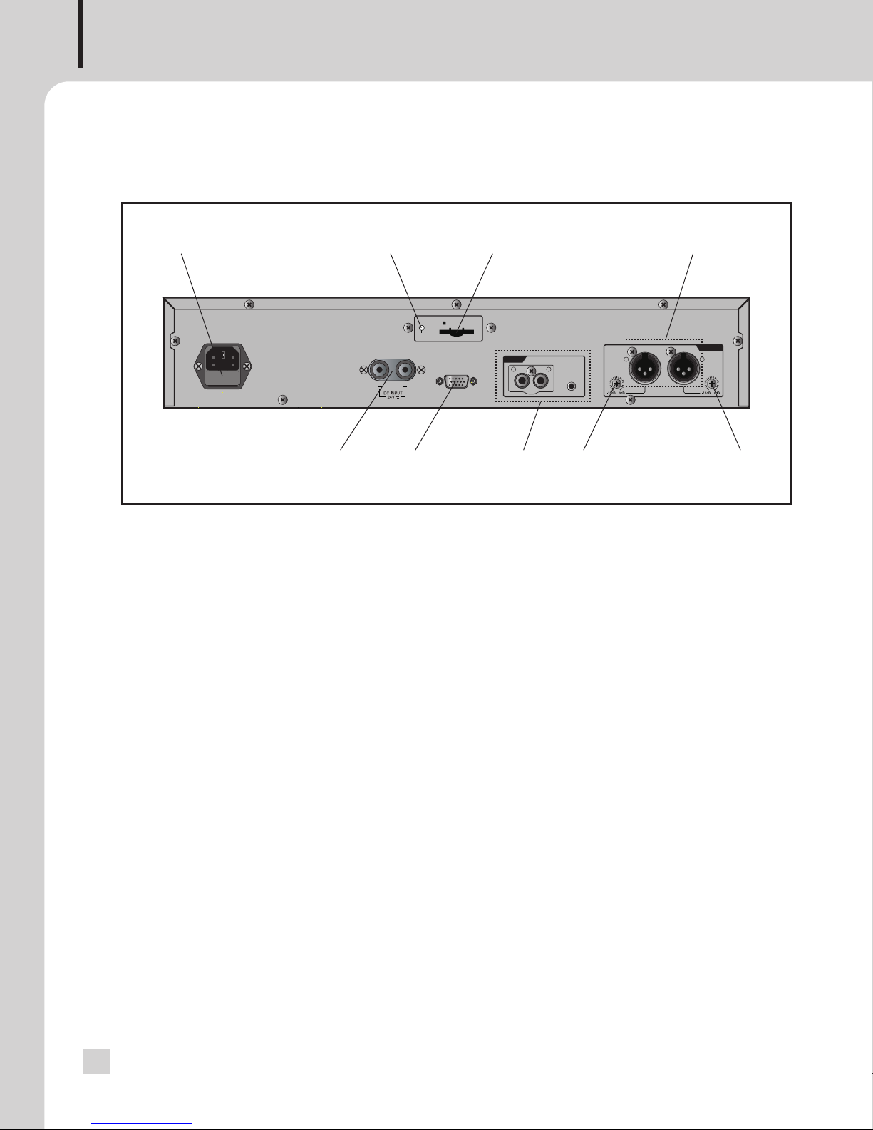
1. AC INPUT TERMINAL
It is a terminal to input AC power. Fuse cap containing (AC 220-240V, 50/60Hz) AC power fuse is
mounted. (FUSE: T315mA/250V)
2. SD CARD OPERATION STATUS DISPLAY LED
It is a LED to display the operation status of SD CARD. Green LED flashes when SD CARD is under
Read/Write status.
3. SD CARD SLOT
It is a slot to mount SD CARD. Basically 8GB of SD CARD is provided.
- SD Card supported capacity: Up to 32GB
- File system: FAT 32 (NTFS unsupported)
4. DC POWER INPUT TERMINAL
It is a terminal to input DC 24V power.
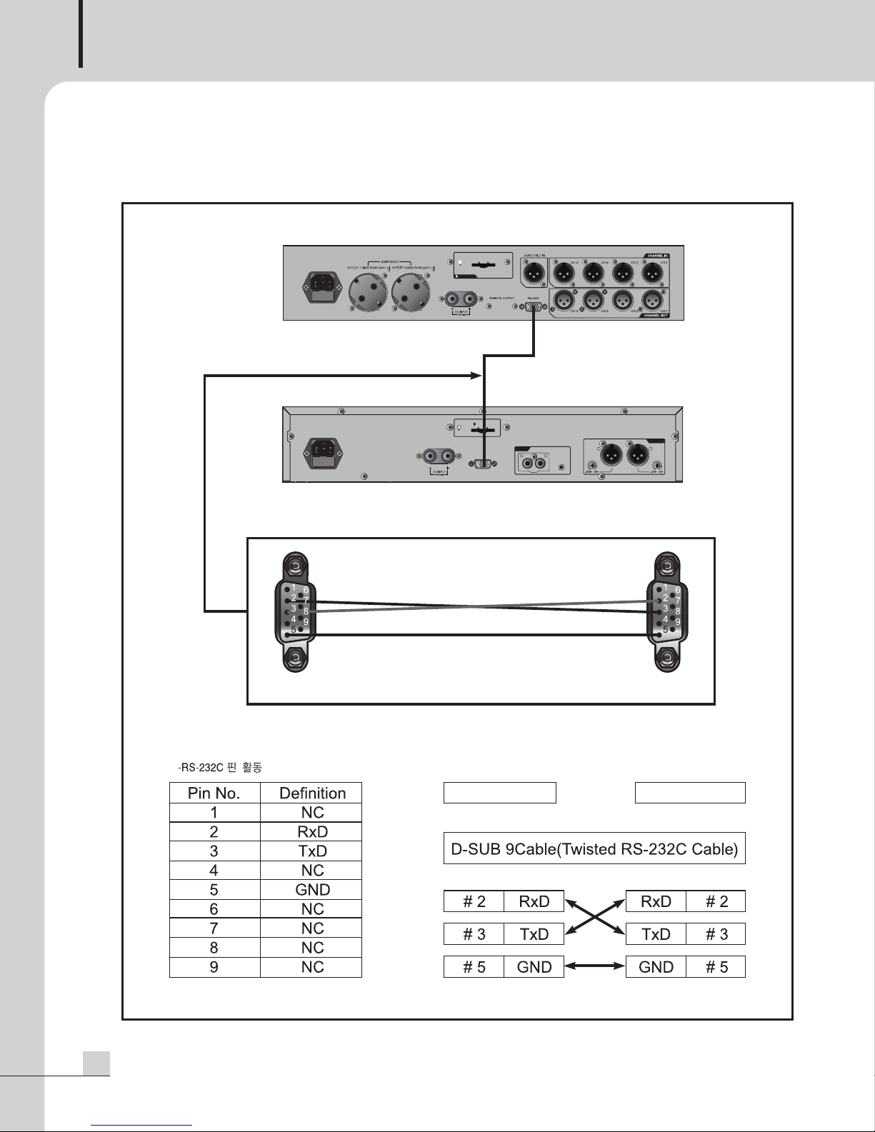
5. RS-232 TERMINAL
It is a terminal to connect with PW-6242B. According to the saved schedule in PW-6242B, our product, you
can control the equipment or connect ER-6116 (Emergency Router) to play EM scenario message.
6
PV-6232A
Page 9
MULTI VOICE FILE
AUX
CD
R
L
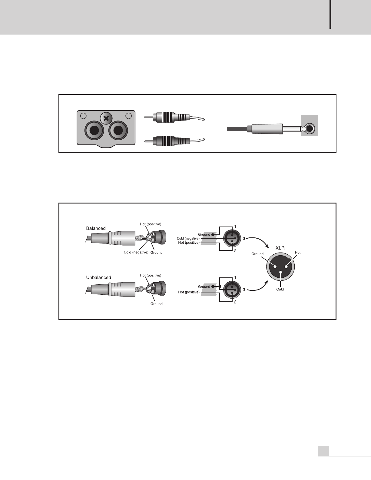
6. AUDIO INPUT TERMINAL
It is an audio input terminal enabling to connect with source devices including CD player. It is configured
with RCA input terminal and AUX input terminal. Refer to the following for the cables needed to the terminal.
RCA terminal AUX terminal
7. AUDIO OUTPUT TERMINAL
It is an audio output terminal. It is divided into L channel and R channel. You can also use as MONO type
depending on output setting. Please use the balanced cable. When using the unbalanced cable, refer to
below figure to connect it.
XLR JACK
8. AUDIO OUTPUT LEVEL ADJUSTING VOLUME
It can adjust the level of audio output. It can adjust from 0dB to 15dB.
PV-6232A
7
Page 10
MULTI VOICE FILE
Root
현재 폴더 위치
하위 폴더
하위 폴더
INTER-M
USER
TOP
USER
현재 폴더 위치
하위 폴더
폴더 내 파일
TEST FOLDER
File Name.mp3
선택 한 위치
File Name2.mp3
Folder Name
File Name.mp3
REPEAT AL L
AUTO
TR-0001
PLAY
1 2
4
7
6
3
5
How to Operate
How to Operate
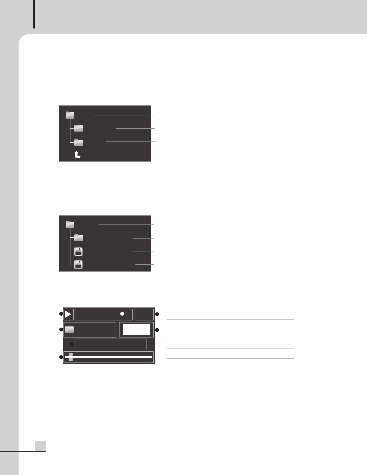
1. Sound Source Selection
You can choose the sound source via file tree structure.
Current folder location
Sub-folder
Sub-folder
1) If you push PARAMETER during initial screen or playing the sound source, it is converted into sound source
selection screen.
2) The file tree structure for selecting folders and sound sources is displayed to display window. If you push
PARAMETER after moving into the desired folder by rotating PARAMETER, the folder is selected. When
selecting TOP, it moves to the top of screen.
3) If you rotate PARAMETER in selected folder, you can choose the sound source file.
2. Sound Source Play
You can play the sound sources saved to USB memory or SD Card by selection.
1) If you push PLAY(▶) button after selecting the sound source file with PARAMETER,
it displays play icon and play time on display window, plays selected sound source file, and lights on LED
of PLAY(▶) button.
2) If you push PAUSE (||) button during playing, it pauses and LEDs of PLAY(▶) & PAUSE(||) buttons flash.
If pushing PLAY(▶) button again, it continues to play.
8
3) If you push STOP() button, the play of sound source is stopped.
PV-6232A
Current folder location
Sub-folder
File in folder
Selected position
➊ Status Icon Play/Stop/Pause Icons
➋ Setup Status Displayed depending on the setup
➌ Track No. Current Track No.
➍ Current Folder Location Folder Icon, Current Folder Name
➎ Status Message PLAY/STOP/PAUSE
➏ Message 1 Name of Playing File
➐ Message 2 Play Progress Bar
Page 11
MULTI VOICE FILE
4) I
f pushing PARAMETER during playing the sound source, the play is stopped and it moves into sound source
election screen. When moved to the sound source selection screen, LEDs of all buttons are turned off.
s
5) If you push STOP(■) button during playing the sound source, the play of sound source is stopped. Under
the stop of sound source play, if pushing STOP(■) button longly, it moves to the defaullt screen.
3. Sound Source Saving
You can save digital sound source files into SD Card.
1) Sizes of all storage media memory are supported from min. 4GB to max. 32GB.
2) For the file system of storage device, only FAT 32 is supported. Format PC with FAT 32, then use.
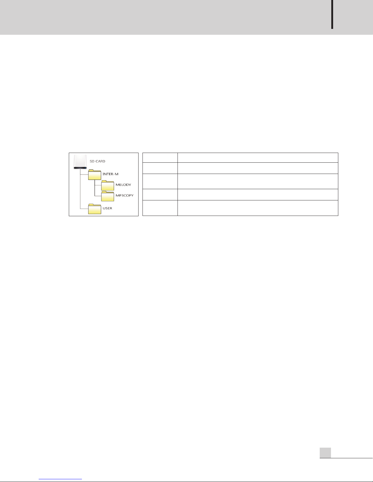
3) Sub-folder structure is supported and refer to the below picture for default folder structure of file system.
Folder Name Content
INTER-M
AUTOPLAY
RECORD
USER
It is a default folder of storage device.
It is a folder that automatic playing MP3 file (EMORG.MP3) is saved when using
Auto Play function.
It is a folder to save recorded file in case of using sound source recording function.
It is a default folder for user to save the sound source. You can create folders
freely to the sub-folder.
※ CAUTION
1) Set up the file structure inside SD Card as above. If you modify or delete folder name arbitrarily, it will
not be operated normally.
2) Under the status that it is connected with PC via USB cable, the function and system will not be operated.
When using the function, remove the cable connected to PC and then proceed the function.
3) It is faster in file uploading/downloading speed by mounting SD Card directly onto PC rather than
uploading/downloading the file by connecting with PC after mounting SD Card onto the equipment.
When uploading/downloading the large capacity of file, mount SD Card directly onto PC and then
proceed.
4) When interworking with ER-6116, save the sound source file to the top folder of SD Card. Please add the
number from 001 to 099 before file name in sound source file.
Ex) 01sound source file name.mp3, 002sound source file name.mp3, , 099sound source file
name.mp3
(The name of sound source file can be changed but make sure to add the number before file name.)
4. Recording
You can record the audio signal input with MIC IN terminal in front side and audio input terminal in
backside (RCA, AUX). Input the audio signal to MIC IN terminal in front side or audio input terminal in
backside (RCA, AUX) and then record.
1) If you push REC() button, RECORD WAITING statement is displayed to display window, LED of
REC() button flashes, and it is converted into recording standby status.
2) When recording turns into standby status, the remained capacity of SD Card is displayed to display
window.
3) If you push REC() button again at that time, the recording starts and display window displays the
recording time.
PV-6232A
9
Page 12
MULTI VOICE FILE
SETTING MODE
1. REPEAT SET
2
. AUTO PLAY SET
3. BUADRATE SET
SETTING MODE
4. FILE DELETE
5
. OUTPUT MODE
6. VERSION
REPEAT
REPEAT 1
S
ET
REPEAT
REPEAT FOLDER
S
ET
4) If you push PAUSE (||) button during recording, display window displays RECORD PAUSE statement, the
recording pauses, and PAUSE ( ) and REC(●) buttons flash.
5) If pushing PLAY(▶) button once again, it continues to record. Using this function, the user can record only
esired parts to create one sound source file.
d
6) If you push STOP(■) button, the recording is stopped.
7) If you push PLAY(▶) button after completing the recording, it plays from the last recorded content.
※ When recording after inputting all audio signals to MIC IN terminal in front side and audio input terminal
in backside (RCA, AUX), the audio signal is recorded by mixing.
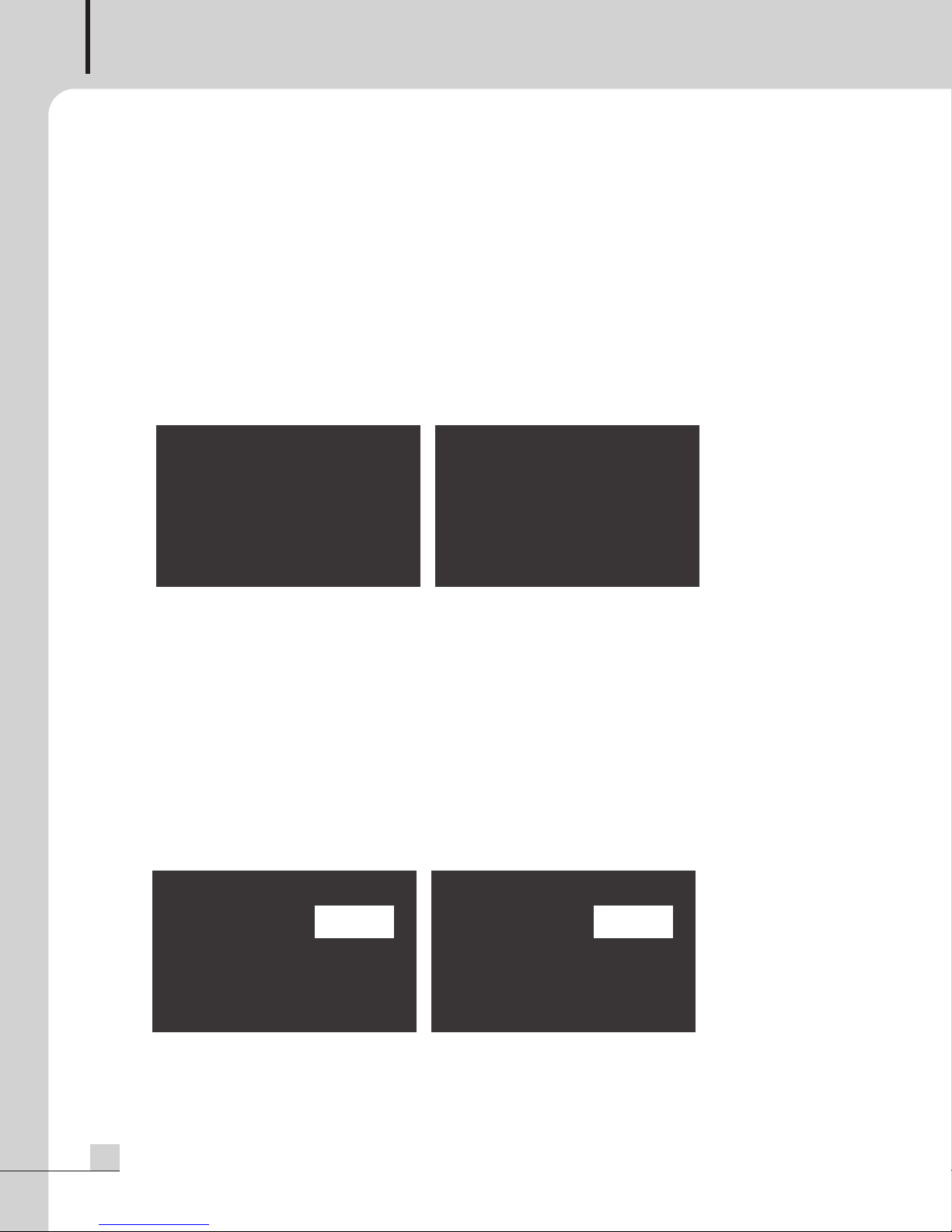
5. Setting Mode
You can set up repeat & play, auto play, communication speed, file deletion, and output mode and check
the firmware version.
5.1 Repeat
1) During default screen or playing the sound source, if you push PARAMETER longly, it is converted into
selection mode.
In setting mode, you can set up repeat/auto play, communication speed, and output mode and delete the file
2)
3) Rotate PARAMETER in setting mode, you can move the setting item.
4) If you push PARAMETER after moving into the desired item, the item is selected.
5) If there is no input for 5 seconds, it moves into the default screen.
6) If the sound source is played at the device, it cannot be moved to FILE DELETE/OUTPUT MODE/VERSION
menu.
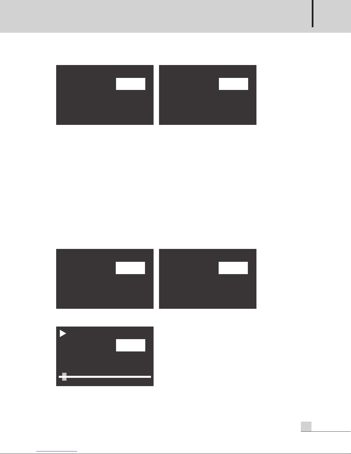
You can play by repeating the playing file. If pushing PARAMETER after moving into REPEAT SET in setting
mode screen, the screen to set up repeat mode displays, and if pushing PARAMETER after changing it into
the desired function by rotating PARAMETER, it is set to due function.
.
10
PV-6232A
Page 13
MULTI VOICE FILE
REPEAT
REPEAT ALL
SET
REPEAT
REPEAT NON
SET
AUTO PLAY
YES
SET
AUTO PLAY
NO
SET
AUTO PLAY
AUTO PLAY
PLAY
5.2 AUTO PLAY
1) REPEAT 1
Playing file is repeatedly played.
2) REPEAT FOLDER
All sound source files in current folder location (excluding sub-folder) are played repeatedly in the
arranged order.
3) REPEAT ALL
Arranged all sound source files are played repeatedly.
4) REPEAT NON
Doesn’t use repeat & play.
When supplying AC or DC power, EMORG.mp3 in AUTOPLAY folder is automatically & repeatedly played.
If pushing PARAMETER after moving into AUTO PLAY in setting mode screen, AUTO PLAY setting screen is
displayed and YES or NO can be selected by rotating PARAMETER. If pushing PARAMETER after selecting
YES or NO, the setting is completed. You can connect with external device auto input terminal of EP
(EMERGENCY PANEL) to use as emergency sound source.
1) If AUTO PLAY is activated, AUTO PLAY statement is displayed on the top of display window.
2) When playing the sound source with AUTO PLAY activated, any button other than STOP button does not
operate.
PV-6232A
11
Page 14
BaudRate
9600 bps
SET
BaudRate
19200 bps
SET
Root
현재 폴더 위치
하위 폴더
하위 폴더
INTER-M
USER
TOP
MULTI VOICE FILE
5.3 Communication Speed (Baud Rate) Setting
3) If pushing STOP button, the play stops and it moves into the default screen.
※ Caution: Be cautious that if file name and folder configuration are wrong, it does not play normally.
Folder name - AUTOPLAY, file name - EMORG
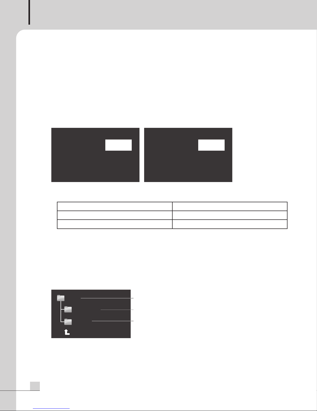
When connecting this device with PW-6242B, you can set up communication speed for each product. In
case of unmatched communication speed, you cannot control with RS-232 communication terminal and
therefore, set up the proper communication speed. If pushing PARAMETER after moving into BAUDRATE in
setting mode screen, BAUDRATE setting screen is displayed and you can set up the communication speed by
rotating PARAMETER.
1) You can change the communication speed into 9600BPS/19200BPS by rotating PARAMETER. Refer to
the following to set up the communication speed for the model to be connected.
MODEL BaudRate
PW-6242B 19200 bps
ER-6116 9600 bps
2)
If pushing PARAMETER after changing the communication speed, changed communication speed is set up.
3) If pushing STOP button during setting up the communication speed, the setting is not saved and it moves
into the default screen.
5.4 DELETION
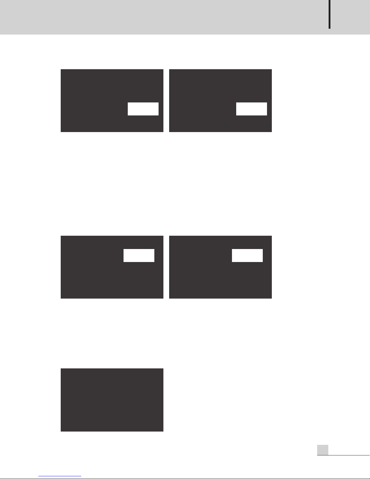
You can select the sound sources file saved to USB memory or SD Card to delete. If pushing PARAMETER
after moving into FILE DELETE in setting mode screen, the screen which enables the selection of file to be
deleted is displayed and you can select the file to be deleted using PARAMETER.
1) Select the file to be deleted by rotating PARAMETER.
2) If selecting the file to be deleted, delete confirmation window is displayed. You can select YES or NO by
rotating PARAMETER. If pushing PARAMETER after selecting YES, the selected file is deleted. If pushing
PARAMETER after selecting NO, the selected file will not be deleted.
Current folder location
Sub-folder
Sub-folder
12
PV-6232A
Page 15
TR-0001
YES
EXREC0001.mp3
File Delete?
TR-0001
NO
EXREC0001.mp3
File Delete?
OUTPUTMODE
STEREO
SET
OUTPUTMODE
MONO
SET
F/W VERSION
ver 1.0.0.0
MULTI VOICE FILE
3) If the deletion of sound source file is completed, File Deleted statement is displayed to display window.
4) During the operations of sound source play & sound source recording, you cannot delete the sound
source.
5) If you push STOP(■) button during deleting the sound source, the deletion is canceled.
6) If all of melodies saved to SD Card are deleted, NO FILE statement is displayed to display window.
5.5 OUTPUT Mode Setting
You can select the output mode of this device between STEREO and MONO. If pushing PARAMETER after
moving into OUTPUT MODE in setting mode screen, the screen to set up the output mode and you can
change the output mode by rotating PARAMETER.
1) You can set up the output mode as STEREO or MONO by rotating PARAMETER.
2) If pushing PARAMETER after selecting STEREO or MONO, it is set up as the output mode.
5.6 Firmware Version Verification
You can verify the firmware version of this device. If pushing PARAMETER after moving into VERSION in
setting mode screen, firmware version of the device is displayed. The number displayed to the screen varies
depending on the firmware version.
PV-6232A
13
Page 16

MULTI VOICE FILE
6. Uploading & Downloading MP3 File Using USB-B Type Port
After connecting this device with PC, you can upload & download or delete MP3 file from/into PC.
1) When connecting USB B type port in front of this device with PC using USB cable, SD Card mounted to
his device is automatically recognized.
t
Then USB DEVICE statement is displayed to display window of this device and portable disk driver appears
to MY COMPUTER of PC.
2) By double clicking the portable disk, you can upload & download or delete MP3 file.
※ Please connect with PC after booting the product completely. During connecting with PC, all buttons of
equipment will not operate and if you want to use the functions of play, record, and deletion, remove the
cable connected to PC before the use.
※ When connecting with PC via USB cable during playing the sound source, the equipment may show the
malfunction. Do not connect with PC via USB cable during playing the sound source.
14
PV-6232A
Page 17
ACCESS
AC INP UT
3
50mA
S
D MEMORY
ACCESS
R
S-232C
R
L
S
D
MEMORY
AC INP UT
250mA
CD
L
EVEL
LEVEL
A
U
X
INPUT
OUTPUT
R L
PV-6232A
PC-6335
CD-6208
PW-6242B
PA- 631 2
PA- 632 4
PD-6359A
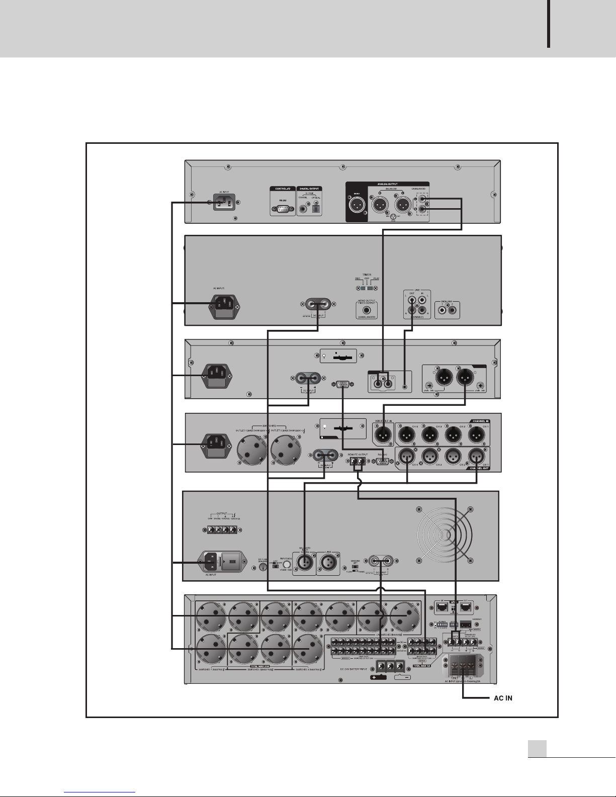
Application
Application
MULTI VOICE FILE
PV-6232A
15
Page 18
MULTI VOICE FILE
ACCESS
AC INPUT
3
50mA
SD MEMORY
A
CCESS
R
S-232C
R
L
S
D MEMORY
AC INPUT
2
50mA
C
D
LEVEL
LEVEL
A
UX
INPUT
O
UTPUT
R L
PW-6242B
PV-6232A
PV-6232A(Female)
PW-6242B(Female)
PV-6232A PW-6242B
RS-232C Connection
RS-232C Connection
16
PV-6232A
Page 19
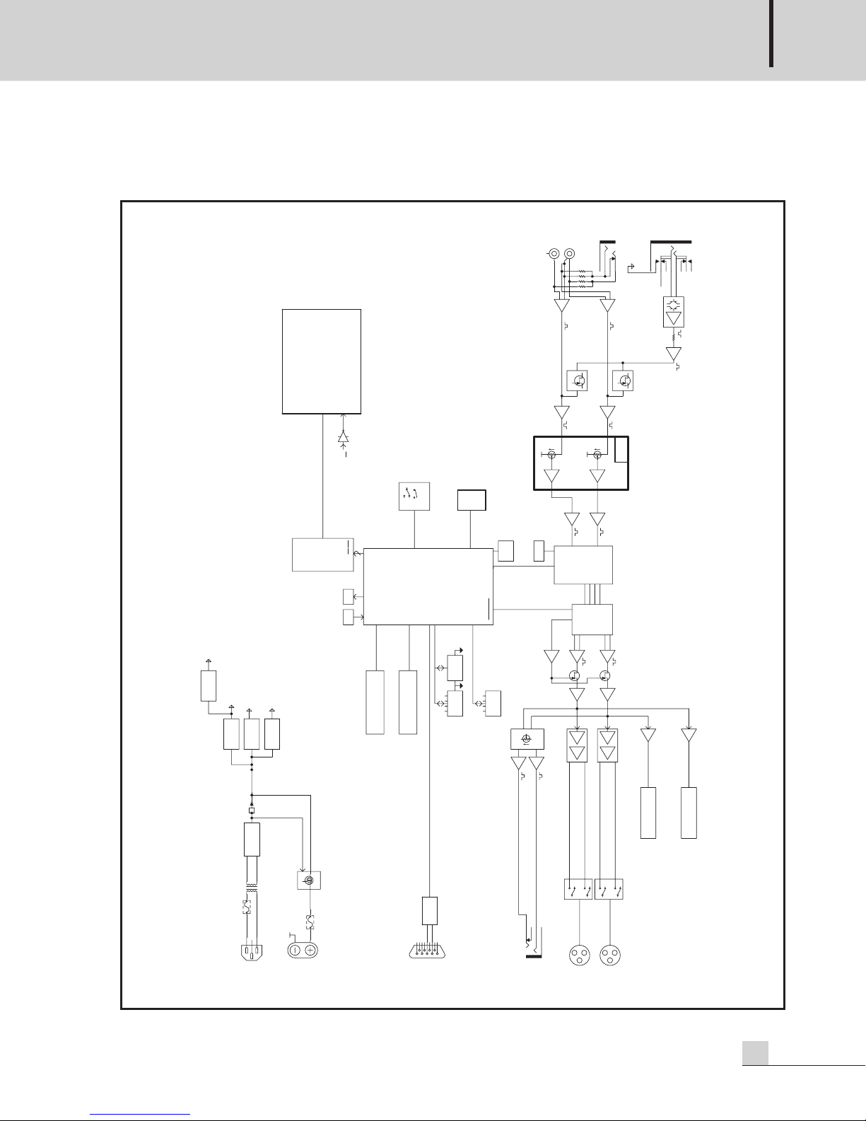
Block Diagram
+24V
Bridge
DC-DC
+5V
+3.3V
AC Inlet
Input
+14V
-14V
ON : Vt < 18V
Vt
Fuse
7$9
RS-232
RS-232C
RCA
CD
L
R
Input
-10dBu
Input
-10dBu
SD Card
8GB
1
2
3
Output
1
2
3
Output
Type A
USB
USB
Type B
Current Limited
VBUS
+5VD
G:+36~+48dB
R
G:+4dB
G:+4dB
G:+0dB
G:+0dB
U-COM
Live
LED
8MHz
SRAM
4Mbit
BHE,
BLE
LCD, STN, 128*64
-50dBu
+3.3V
G:+10dB
Front B'd
FR4 2layer
G:-15dB
G:-15dB
Fc:40kHz
Fc:40kHz
G:+0dB
G:+0dB
MIC_SEL
DAC
BCLK
MCLK
LRCK
SDAT
MP3 EN/DEC
12.288MHz
Fc:44kHz
G:+9.6dB
Fc:44kHz
G:+9.6dB
G:0dB
G:0dB
A/BMUTE
Crossed FB
G:0dB
24V / 9.6mA
Crossed FB
G:0dB
24V / 9.6mA
G:-10dB
G:-10dB
NJM3414AV
Phones Volume
LED
-24, -18, -12, -6, -3, 0, Over
LED
-24, -18, -12, -6, -3, 0, Over
G:+3dB
G:+3dB
250mW/50ohm
USB
Type B
Type A USB
RST_VS1063A
SPI,CCS,DREQ
AD0~7
WR
EN
Push Encoder
A
B
Push
STOP PLAY
Momentary Switch
LED
PAUSE REC
STOP PLAY PAUSE REC
Reset
Switch
DC-DC
DC-DC
DC-DC
Power Distribution
DC24V
D-SUB09P
PHONE04P
1
234
5
6
789
PHONE09P
PMBFJ112
PMBFJ112
c
.w
10KA
c
.w
10KA
c
.w
2
0KA*2
PHONE JACK
Block Diagram
MULTI VOICE FILE
PV-6232A
17
Page 20
MULTI VOICE FILE
Specifications
Specifications
PV-6232A
Communication method RS-232C PC INTERFACE
Rated output
(1kHz, MIC -50dBu,CD -10dBu, AUX -10dBu)
Play mode output level
(1kHz 0dBFS Play, Max. Volume)
HEAD PHONE OUTPUT Maximum 250mW / 50Ω
AUX IN 40Hz~20kHz
Frequency characteristics
(Output at Rated ±3dB)
Input sensitivity / Impedance
Recording mode Signal to Noise (20kHz LPF) > 58dB
Play mode Signal to Noise
(20kHz LPF, 1kHz 0dBFS MP3 Play)
THD (20kHz LPF) < 0.1 %
Operating Temperature
CD IN 40Hz~20kHz
MIC IN 40Hz~200kHz
AUX IN -10dB / 10kΩ (UNBAL)
CD IN -10dB / 10kΩ (UNBAL, L+R)
MIC IN -50dB / 2kΩ (BAL)
0dBu
Maximum +20dBu
> 100dB
-10℃ ~ +40℃
Power Source AC 220-240V, 50/60Hz, DC 24V
Power consumption 15W
Weight (set) 4.35kg / 9.59lb
Dimension (set)
* Design and specification are subject to be changed for the improvement of product quality without pre notice.
※ Caution: This device is for business and is completed in Electromagnetic Compatibility Registration. Seller or
User should be cautious for this point and if selling or purchasing wrongly, exchange into the device
for home. (Class A Product)
18
PV-6232A
482(W) × 88(H) × 280(D)mm / 19(W) × 3.5(H) × 11(D)in
Page 21
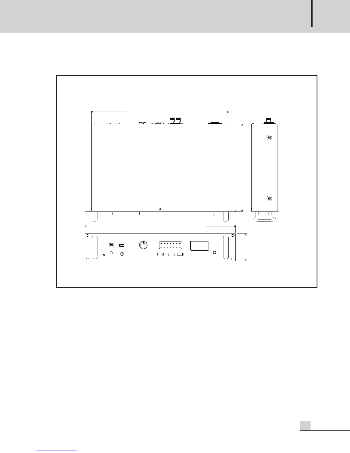
※ DIMENSIONS
88
280
440
482
MULTI VOICE FILE
PV-6232A
19
Page 22

MULTI VOICE FILE
Service
Service
Procedures
Take steps to insure the problem is not related to operator error or other products within the system. Information
provided in the troubleshooting portion of this manual may help with this process. Once it is certain that the
problem is related to the product contact your warranty provider as described in the warranty section of this
manual.
Schematic
A Schematic is available by contacting your warranty provider.
Parts List
A Parts List is available by contacting your warranty provider.
Variations and Options
Variations and Options
Variations
Products supplied through legitimate sources are compatible with local AC power requirements.
Options
No optional items are available for this product.
Warranty
Warranty
Warranty terms and conditions vary by country and may not be the same for all products. Terms and conditions
of warranty for a given product may be determined first by locating the appropriate country which the product
was purchased in, then by locating the product type.
To obtain specific warranty information and available service locations contact Inter-M directly or the
authorized Inter-M Distributor for your specific country or region.
20
PV-6232A
Page 23

Page 24
Inter-M, Ltd. (Korea) began operations in 1983.
Since then, Inter-M has grown to become one of the largest manufacturers
of professional audio and commercial sound electronics equipment in the world.
Inter-M has gained worldwide recognition for its own branded products,
as well as private label manufacturing of electronics sold under other names (OEM).
The company is no longer just a Korean company, but rather a global company
that is truly international in scope, with factories and offices in Korea and China,
and sales and marketing operations located in Japan, Europe, and the U.S.A.
With more than 850 employees around the globe,
Inter-M is well-poised for further growth and expansion.
Inter-M Americas, INC.
5666 CORPORATE AVE. CYPRESS, CA 90630
TEL : +1-714-828-2200, FAX : +1-714-828-2210
Home Page : http://www.inter-m.net, E-mail : [email protected]
Inter-M Corporation
SEOUL OFFICE : 719, DOBONG-RO, DOBONG-GU, SEOUL, KOREA
TEL : +82-2-2289-8140~8, FAX : +82-2-2289-8149
Home Page : http://www.inter-m.com, E-mail : [email protected]
MADE IN KOREA
November 2017 141351
 Loading...