

Page 1
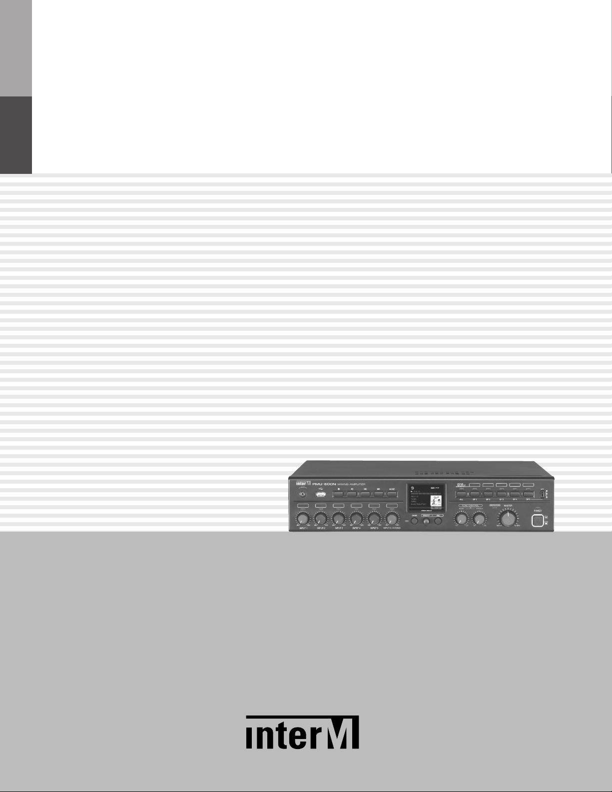
Operation Manual
Mixing Amplifier
PMU-360N/480N/600N
Page 2
MIXING AMPLIFIER
Welcome
Welcome
A personal welcome to you from the management and employees of Inter-M
All of the co-workers here at Inter-M are dedicated to providing excellent products with inherently good value,
and we are delighted you have purchased one of our products.
We sincerely trust this product will provide years of satisfactory service, but if anything is not to your complete
satisfaction, we will endeavor to make things right.
Welcome to Inter-M, and thank you for becoming part of our worldwide extended family!
This s ym bol is intende d to a lert the user to t he
CAutION
RISK OF ELECTRIC SHOCK
DO NOT OPEN
CAUTION: TO REDUCE THE RISK OF ELECTRIC SHOCK.
DO NOT REMOVE COVER (OR BACK).
NO USER-SERVICEABLE PARTS INSIDE.
REFER SERVICING TO QUALIFIED SERVICE PERSONNEL.
Caution: To prevent electric shock do not use this (polarized) plug with
Attentions: Pour prévenir les chocs électriques ne pas utiliser cette
WARNING
To prevent fire or shock hazard, do not
expose the unit to rain or moisture.
*WARNING FOR YOUR PROTECTION PLEASE READ THE FOLLOWING-WATER AND MOISTURE: Unit should not be used near water(e.g.
near a bathtub, washbowl, kitchen sink, laundry tub, in a wet basement, or near a swimming pool, etc). Care should be taken so than objects do
not fall and liquids are not spilled into the enclosure through openings.
*CLASS 2 WIRING (Adjacent to speaker terminal): The speaker output of this apparatus can exceed 10 Watts and could be a shock injury.
Connection to speakers should be performed by a skilled person.
*Do not install this equipment in a confined space such as a book case or similar unit.
*This apparatus shall not be exposed to dripping or splashing and no objects filled with liquids, such vases, shall be placed on the apparatus.
*This apparatus shall be connected to a mains socket outlet with a protective earthing connection.
It has heed to be easy to disconnect the device. To disconnect the device from power, separate AC input cable from inlet or unplug the AC Cord.
*
CAutION
*These servicing instructions are for use by qualified service personnel only. To reduce the risk of electric shock, do not perform any servicing
other than that contained in the operating instructions unless you are qualified to do so.
NOtE
*This equipment has been tested and found to comply with the limits for a Class A digital device, pursuant to Part 15 of the FCC Rules. These limits are
designed to provide reasonable protection against harmful interference when the equipment is operated in a commercial environment. This equipment
generates, uses, and can radiate radio frequency energy and, if not installed and used in accordance with the instruction manual, may cause harmful
interference to radio communications. Operation of this equipment in a residential area is likely to cause harmful interference in which case the user will
be required to correct the interference at his own expense.
presence of uninsulated “dangerous voltage” within
the prod uct’ s enclo sure that may be of su fficien t
magnitude to constitute a risk of electric shock to
persons.
This s ym bol is intende d to a lert the user to t he
presence of important operation and maintenance
(servicing) instructions in the literature accompanying
the appliance.
an extension cord, receptacle or other outlet unless the blades
can be fully inserted to prevent blade exposure.
fiche polarisée avec un prolongateur, une prise de courant
on une autre sortie de courant, sauf si les lames peuvent
étre ins ér ées à fo nd sans e n laisser auc un e pa rtie à
découvert.
Page 3

MIXING AMPLIFIER
Contents
Contents
Unpacking .......................................................................................................................................2
Installation
Environment....................................................................................................................................2
Important Safety Instructions.............................................................................................................2
Features............................................................................................................................................3
Operation ........................................................................................................................................3
Front Panel ......................................................................................................................................4
Rear Panel .......................................................................................................................................8
Web Setting...................................................................................................................................13
1. Accessing PMU-N Series Web-page...........................................................................................13
2. Network Setting ........................................................................................................................13
3. Operation Mode Setting ............................................................................................................14
4. Internet Radio Setting.................................................................................................................15
5. AOE Stream Setting...................................................................................................................18
6. Time Setting..............................................................................................................................19
7. Log View ..................................................................................................................................20
8. Upgrade...................................................................................................................................21
9. Rebooting.................................................................................................................................22
10. Factory Setting ........................................................................................................................22
11. Password Setting .....................................................................................................................23
Speaker Connection.....................................................................................................................24
System Connection.......................................................................................................................26
Block Diagram ..............................................................................................................................27
Specifications ................................................................................................................................28
Service
Procedures....................................................................................................................................30
Schematic.....................................................................................................................................30
Parts List .......................................................................................................................................30
Variations and Options ...............................................................................................................30
Warranty .......................................................................................................................................30
PMU-360N/480N/600N
1
Page 4

MIXING AMPLIFIER
S
3125A
Unpacking
Unpacking
Although your PMU-360N/480N/600N is neither complicated nor difficult to operate, we recommend you
take a few minutes to read this brief manual and familiarize yourself with the important information regarding
product features, setup and operation.
As with most electronic devices, we strongly recommend you retain the original packaging. In the unlikely event
the product must be returned for servicing, the original packaging (or reasonable equivalent) is required.
Installation
Installation
Environment
Never place this product in an environment which could alter its performance or reduce its service life. Such
environments usually include high levels of heat, dust, moisture, and vibration.
IMPORTANT SAFETY INSTRUCTIONS
1. Read these instructions.
2. Keep these instructions.
3. Heed all warnings.
4. Follow all instructions.
5. Do not use this apparatus near water.
6. Clean only with dry cloth.
7. Do not block any ventilation openings. Install in accordance with the manufacturer’s instructions.
8. Do not install near any heat sources such as radiators, heat registers, stoves, or other apparatus (including
amplifiers) that produce heat.
9. Do not defeat the safety purpose of the polarized or grounding-type plug. A polarized plug has two blades
with one wider than the other. A grounding type plug has two blades and a third grounding prong. The wide
blade or the third prong are provided for your safety. If the provided plug does not fit into your outlet, consult
an electrician for replacement of the obsolete outlet.
10. Protect the power cord from being walked on or pinched particularly at plugs, convenience receptacles, and
the point where they exit from the apparatus.
11. Only use attachments/accessories specified by the manufacturer.
12. Use only with the cart, stand, tripod, bracket, or table specified by the manufacturer, or sold with the apparatus.
When a cart is used, use caution when moving the cart/apparatus combination to avoid injury from tip-over.
13. Unplug this apparatus during lightning storms or when unused for long periods of time.
14. Refer all servicing to qualified service personnel. Servicing is required when the
apparatus has been damaged in any way, such as power-supply cord or plug is
damaged, liquid has been spilled or objects have fallen into the apparatus, the
apparatus has been exposed to rain or moisture, does not operate normally, or has
been dropped.
S3125A
2
PMU-360N/480N/600N
Page 5

MIXING AMPLIFIER
Features
Features
- Internet Radio
Plays internet radio over the network.
- AOE-212N streaming
By connecting with Inter-M's network audio streamer (AOE-212N), plays the audio streaming data in real time.
- USB Memory playback (MP3, WAV, FLAC, AAC)
Plays sound sources in USB memory stick.
- USB Audio Stream
Plays the sound of connected PC
- 2.8" Color TFT LCD
Displays the output level, playback and system infomation
- 2U Size
- 360W/480W/600W output power
- SMPS delivers high power output with low power consumption and weight reduction
- 5 Microphone/Line Inputs, EXT IN and TELL IN with individual volume control
- Input Level LED Monitor per channel
- Separate BASS/TREBLE Tone Controls
- 5 zone selection switches
- Independent built-in Attenuator over Zone 5 (Maximum 50W, more than 200Ω)
- PRIORITY
- Remote MUTE and CHIME terminal
- VCA Remote volume controll
Operation
Operation
1. Make sure the power switch on the front of the unit is set to off and connect the power cord to the mains
outlet. Please set each input volume control to minimum position and set the tone controls to 0dB before
turning on the power switch.
2. Make sure the speaker cables and input cables are properly connected.
3. Before connecting power, always check the voltage of main power supply. (AC 220V or AC 110V)
4. After completing all connections, turn on the power switch, and check to confirm that the power indicator
lights.
5. Use input level control for corresponding to desired mixing volume levels and set the output level with master
volume control.
6. Use the Treble/Bass tone controls to change the tone of the output source.
PMU-360N/480N/600N
3
Page 6
MIXING AMPLIFIER
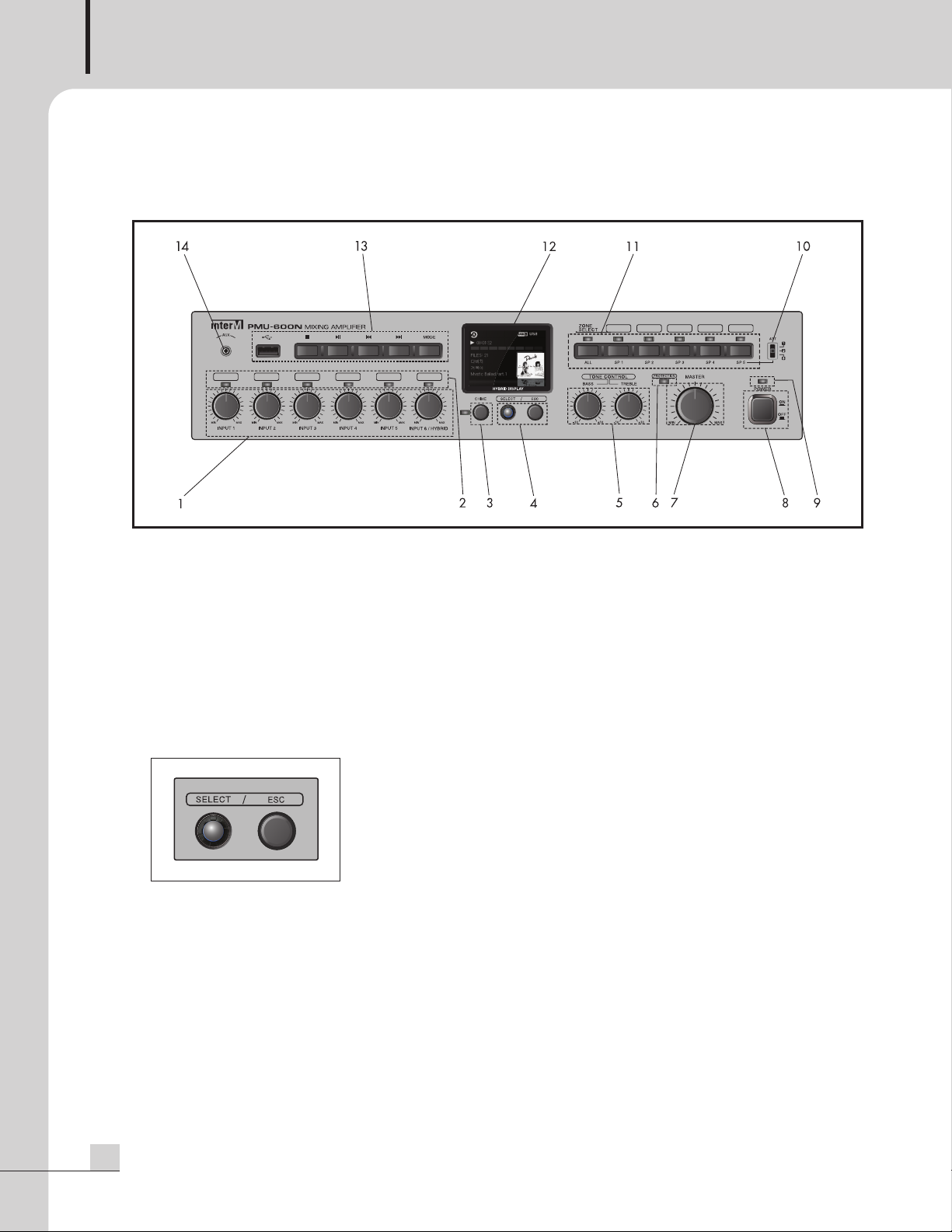
Front Panel
Front Panel
1. INPUT LEVEL CONTROL
Controls the level of each of the six input channels.
2. INPUT SIGNAL INDICATOR
These LEDs light green when input signal is present.
3. CHIME SWITCH
It activates the four tone chime circuitry. The chime indicator lights green when chime is on use.
4. ROTARY ENCODER CONTROL PROGRAM SELECTION DISPLAYED ON THE LCD DISPLAY
- SELECT
The select button activates MENU mode when pressed and held for a few seconds, then it is used as the
select button during menu navigation.
- ESC
It used to return to the OPERATION MODE from the MENU MODE
5. TONE CONTROL
Controls the bass (100Hz) and treble (10kHz) tones of the main amplifier output.
6. PROTECTION MODE INDICATOR
Indicated that the amplifier is in failure protection mode.
4
PMU-360N/480N/600N
Page 7
MIXING AMPLIFIER
7. MASTER VOLUME CONTROL
he master volume control to collectively control the sound level of all outputs and by turning the knob
T
clockwise to increase the volume and counterclockwise to decrease it.
8. POWER SWITCH
9. POWER INDICATOR
This LED Lights green when the unit is powered on.
10. ATTENUATOR
Built-in ATTENUATOR over zone 5, It allows to decrease the output volume independently from master volume.
Mode 100V Output 70V Output
Switch mode 1 100V 70V
Switch mode 2 70V 49V
Switch mode 3 50V 35V
※Caution : ZONE 5 is output terminal with ATTENUATOR function, and a recommended speaker is lower
than 50W(total impedance is upper than 200Ω). Please be careful of connecting the speakers.
11. ZONE SELECTION SWITCH
Use the zone selection switches to route the program audio from the amplifier output to speaker zone 1
through zone 5. The All button controls turns ON/OFF all zones. The Indicators lights on when zone
selection switches indicates if the zone is on.
12. LCD OPERATION DISPLAY
Displays the output level meter, each bar is marked in intervals of 3 to 5dB.
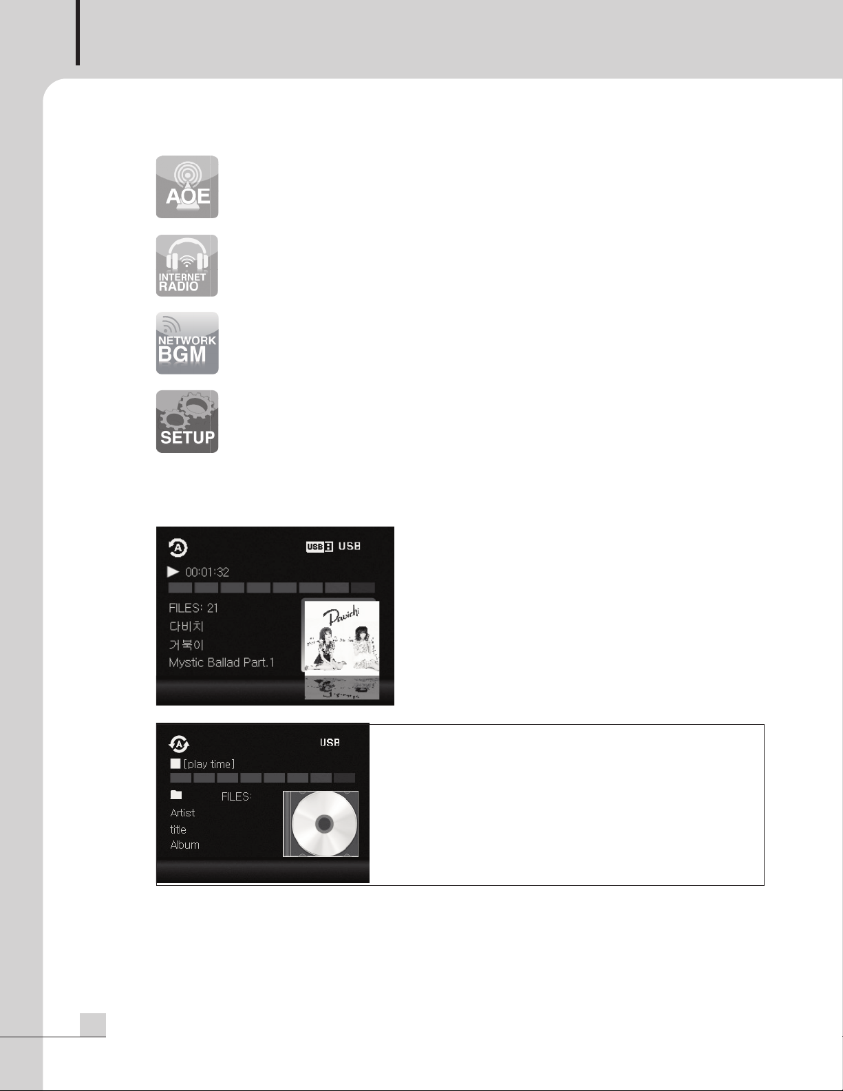
1) MENU MODE
<Menu Selection Screen>
- Menu selection screen will be shown by pressing and holding the select button, choose the menu by
turning the select knob to the right or left then select the desired menu by pressing select button briefly.
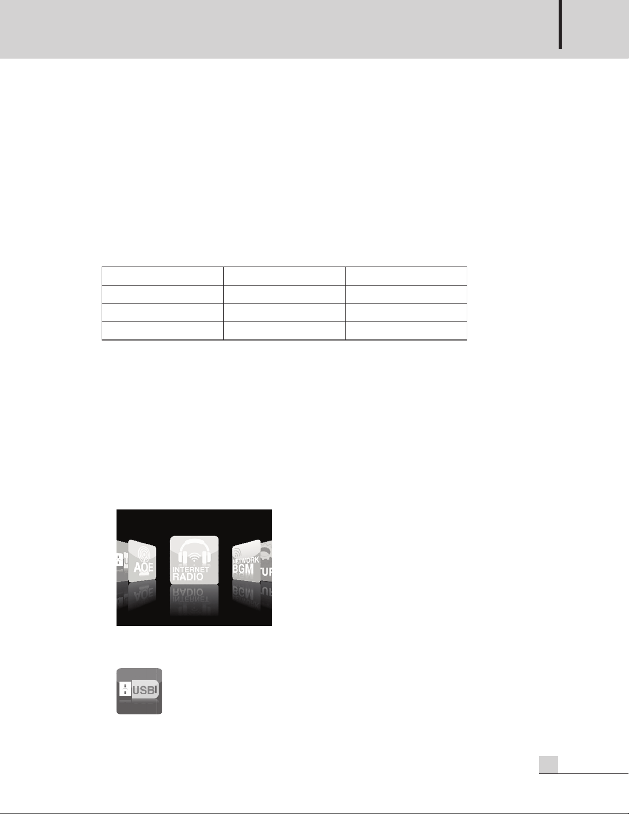
USB PLAYBACK MODE
USB Memory Playback, USB Audio Stream
PMU-360N/480N/600N
5
Page 8
MIXING AMPLIFIER
AOE STREAM MODE
Real time data transfering with AOE over the network.
INTERNET RADIO
Playing Internet Radio.
NETWORK BGM
Real time music broadcasting (service is in preperation).
SETUP
Display system information and firmware version.
2) USB Play Mode
Plays the sound sources of USB memory stick.
Play Mode Icon.
Single, single repeat, folder, folder repeat, play all, repeat all.
Input source display - MP3 Player, Internet Radio, AOE Stream
Receiver.
Output level meter display.
Displays number of Folder and File.
Displays the information of song.
Displays USB connection status.
※Caution : Downloaded sound source through some unclear path might not be able to support seamless
6
PMU-360N/480N/600N
playback.
Illegal distribution of sound file such as MP3 is prohibited by the law.
Please use the sound source that downloaded through the legal path.
Page 9
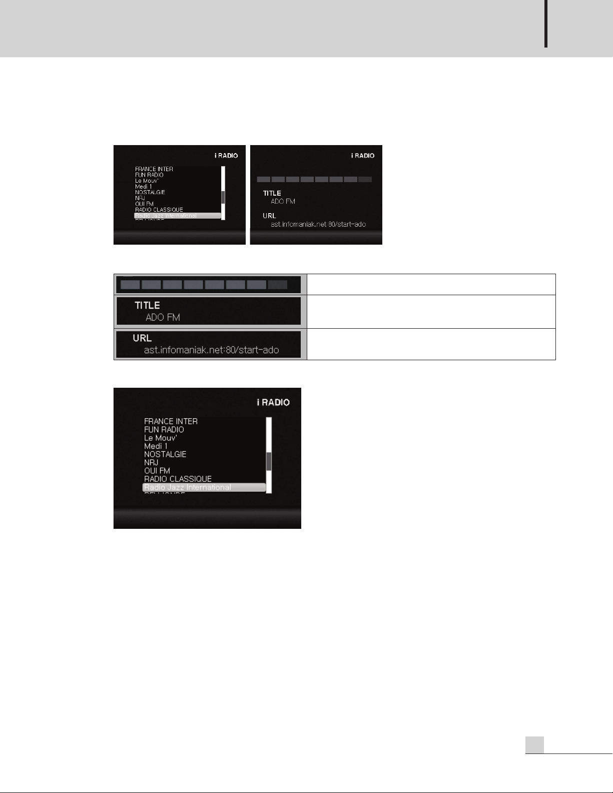
3) Internet Radio
lays internet radio with radio station's URL through network connection.
P
< radio list & radio main >
Displays Broadcasting station.
Output level meter display.
MIXING AMPLIFIER
Displays the URL of broadcasting station.
By pressing the select button briefly, the station lists are displayed as shown below.
Choose the desired station by turning the select button to right or left then press the select button briefly to
play the station you select.
※The internet radio station will be set through web page and you may not be able to receive the
broadcast when the station is no loger in service or doesn't exist.
To set the internet radio, please refer to section of web setting '4. internet radio setting'.
PMU-360N/480N/600N
7
Page 10
MIXING AMPLIFIER
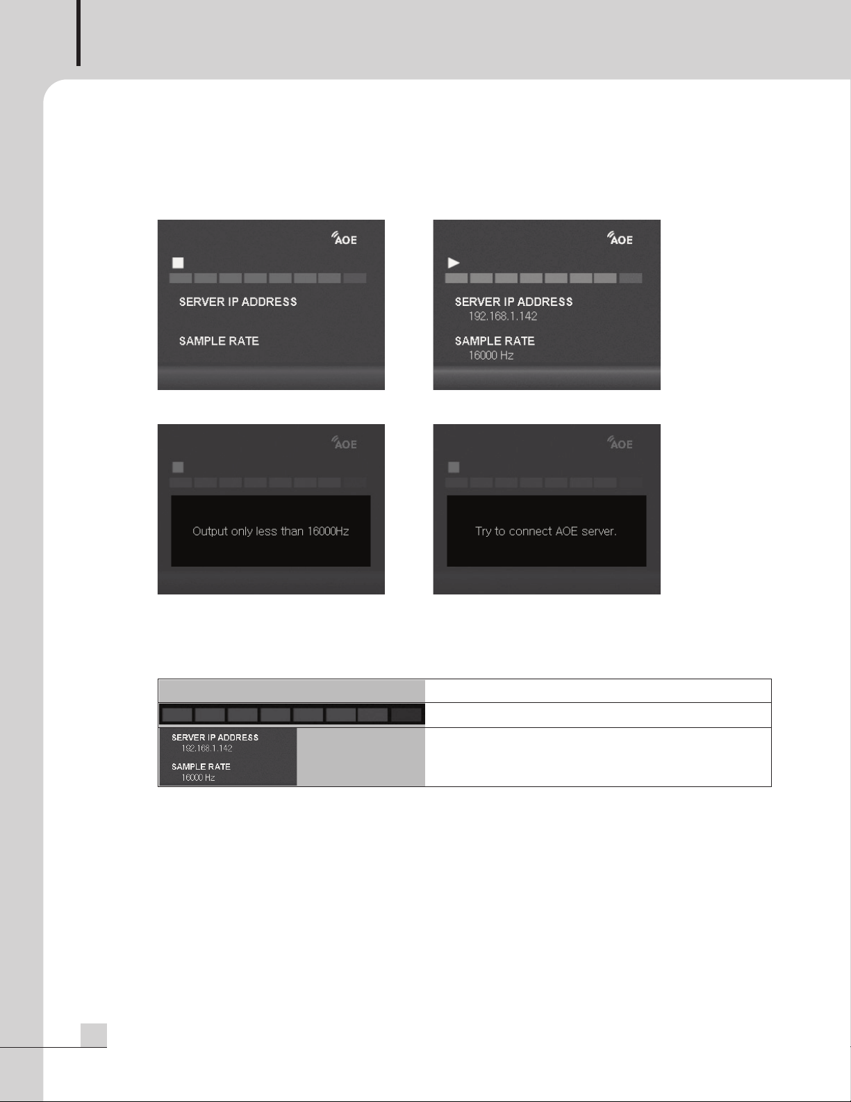
4) AOE stream
y connecting with Inter-M's network audio streamer (AOE-212N), plays the audio streaming data in
B
real time over the network.
<AOE Stream mode screen> <AOE Stream play mode screen>
When AOE's sample rate is more than 16kHz
<
※Caution : for the reliable operation of AOE streaming, the sample rate of AOE -212N is recommmeded
to set as 16000Hz.
/
▶
※AOE setting : Please refer to the section of web setting ‘5. Aoe Stream’.
◼
> <AOE connection error screen>
Dispay the connection status of AOE
Displays the output level
Displays the server address of AOE-212N, The server
setting can be changed through web page.
8
PMU-360N/480N/600N
Page 11
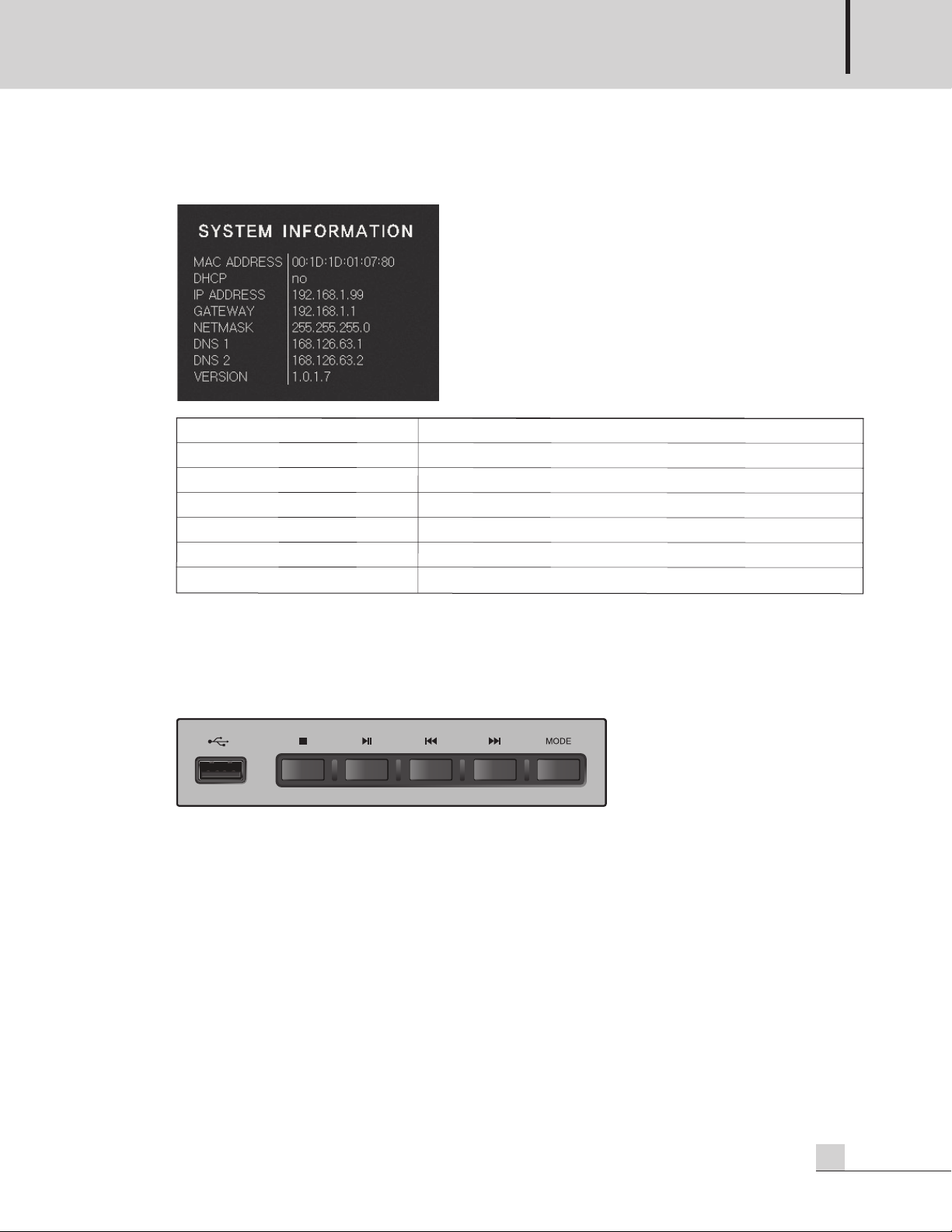
5) System Information Screen
MAC
A
DDRESS
DHC
P Display
IP
A
DDRESS
G
A
T
EW
A
Y
NET
MA
SK
DNS1
,
2 Display
V
ERSION Display
Display
Display
Display
Display
s
default
s
DHC
s
IP
s
G
s
NET
s
DNS
s
Soft
P
set
address
A
T
EW
MASK
address
ware
MA
t
in
A
Y
Version
C
A
DDRESS
g
address
address
MIXING AMPLIFIER
of
equipmen
t
※DHCP setting : Please refer to section of web setting ‘2. network setting’.
13. USB PLAYBACK BUTTONS
1) USB input port
Insert a USB memory stick into the USB port.
※It may cause a problem ejecting a memory stick while music file in USB is playing.
2) ■Stop button
3) ▶▶/ IIplayback / pause button
4) I◀◀, ▶▶Iprevious / next button
Moves to previous or next song by pressing the button and moves to previous or next folder by pressing
the button for more than 2 second.
5) MODE button
Sets the play mode by pressing the button in regular sequence.
All song repeat all song random play all song randomly repeat single song play single song
repeat folder play folder random play folder random repeat All song repeat.
14. AUX INPUT
3.5mm Tip Ring Sleeve (TRS) jack on the front panel.
PMU-360N/480N/600N
9
Page 12

MIXING AMPLIFIER
Rear Panel
Rear Panel
1. AC MAINS (AC INLET)
It accepts a standard IEC mains cable, provided.
2. REMOTE CHIME SWITCH TERMINAL
This terminal is used to activate the 4 tone chimes remotely.
3. MANUAL MUTE TERMINAL
When these two terminals are shorted, the output signal is blocked and the protection indicator on the front
panel flashes.
4. VCA (VOLTAGE CONTROLLED AMPLIFIER) TERMINAL
These two terminals provide connection for an external potentiometer. When the potentiometer is connected,
it allows for remote control of the master volume level.
Note that individual input volume control positions limit the maximum output level adjustable with the remote
volume control.
※Make sure not to set the main volume control to minimum level.
- Connection of remote volume control
Remote Volume
10
Volume Control
10KΩ
※Note : Negative terminal should not be grounded. Never connect it to the unit's chassis or other circuit
ground.
PMU-360N/480N/600N
Page 13

MIXING AMPLIFIER
5. TEL IN TERMINAL
his terminal is provided for connection with a telephone exchange system for paging purposes.
T
※NOTE : When the telephone input is active, all other input signal except AMP IN are muted.
6. TEL IN VOLUME CONTROL
It controls the volume of the TEL IN.
7. TEL IN PRIORITY VOLUME CONTROL
It controls the mute level of all other input signal when the TEL IN signal is present
8. INPUT 1~6
INPUT 1~6 are utilized to connect various external sound source devices including MIC, CD, TUNER, and
other.
1) INPUT 1~3 are provided on balanced XLR JACKs and EURO Terminals Each input have a 3 position level
and phantom power selector switch.
- LINE: used for LINE level signal input.
- MIC: used for the MIC level signal input such as dynamic mics.
- PHANTOM: used to power condenser type mics with DC 24V.
※NOTE : Because INPUT 1~3 XLR Jacks are in parallel with the Euro terminal, do not use them
simultaneously.
2) INPUT 4~5 are provided on balanced TRS 1/4 inch JACKs. Each input has a 2 position level selector
switch.
- LINE: used for LINE level signal input.
- MIC: used for the MIC level signal input such as dynamic mics.
3) INPUT 6 is provided on stereo summing RCA JACKs.
9. PRIORITY VOLUME CONTROL
It controls the priority control volume when the signal is inputted to the INPUT 1~2, EXT IN, CHIME and
SIREN.
※The signal from INPUT 1~2, EXT IN, CHIME input has priority over all other input signal and BGM
broadcasting.
10. PC USB STREAM CONNECTION TERMINAL
This is a USB sound card that connects to PC with WINDOWS 7 operating system, It automatically detects
and play USB sound from PC.
11. NETWORK CONNECTION TERMINAL
This is an RJ45 network terminal. It connects the amplifier to the internet using an Ethernet switch, router or
PC. The network port supports 10/100Mbps and Auto MDIX.
12. EXT IN
This line-level input connects an external mixer to the amplifier expanding input channels.
PMU-360N/480N/600N
11
Page 14

MIXING AMPLIFIER
13. MIX OUT
his line-level output connects the amplifier to an external processing unit or recorder.
T
14. SPEAKER OUTPUT TERMINAL
PMU-360N 54V/8Ω 100V/28Ω 70V/14Ω
PMU-480N 62V/8Ω 100V/21Ω 70V/11Ω
PMU-600N 70V/8Ω 100V/16Ω 70V/8Ω
※Please note that SP 1~5 terminal will be controlled by speaker selector switch of front panel.
12
PMU-360N/480N/600N
Page 15

Web Setting
Web Setting
1. Accessing PMU-N Series Web-page
- If IP address has not been set, type the default IP address (192.168.1.99) – by pushing the factory set switch
more than 5 second, the unit will be reset as default mode.
When connected normally, user verification window will pop-up.
Type the created ID and PASSWORD to log in. (Default ID: admin, Password: 1)
※Changing password: please refer to the section of ‘11. password setting’
※Caution : It is better to set and use the assigned password for the security purpose.
Please make a note to keep the assigned password.
MIXING AMPLIFIER
2. Network Setting
This is network setting page. The host name is used for each of identification when multiple unit is in auto
searching mode.
※IP address : Network information automatically set by DHCP (Dynamic IP address) or can be set as Static
IP address.
PMU-360N/480N/600N
13
Page 16

MIXING AMPLIFIER
By pressing select button briefly DHCP setting screen will be shown as below, select YES or NO to complete.
After setting the network by DHCP, it must to be reconnected with a changed IP.
If the network is set as Static IP address, it will be connected automatically with a changed IP.
※Caution : After changing the IP address or network setting , the reconnection must be applied with a
reconfigured IP.
3. Operation Mode Setting
14
One of three different modes can be set. (USB Player/Internet Radio/AOE Stream Receiver)
Dedicated setting page will be shown according to operating mode setting.
PMU-360N/480N/600N
Page 17

4. Internet Radio Setting
MIXING AMPLIFIER
Select the broadcasting station from the Channel list then select broadcasting title from the Channel title then
click the play button to play.
The channel list consists of two different catagoties which are Fixed channel and User defined channel.
Fixed channel consists with 36 preset channels and User defined channel can be strored up to 20 channels.
PMU-360N/480N/600N
15
Page 18

MIXING AMPLIFIER
The station that user create as a preset can be selected in User defined channel.
Please refer to next page for how to create and save a desired station list in the User definded channel.
16
PMU-360N/480N/600N
Page 19

The following window will be shown by clicking the user define button.
MIXING AMPLIFIER
Type the title and URL of desired station then click the set button to finish. Up to 20 channels can be added
or deleted randomly by user.
PMU-360N/480N/600N
17
Page 20

MIXING AMPLIFIER
5. AOE Stream Setting AOE Stream
AOE-212N is Network Audio Stream Server/Client equipment developed by Inter-M. It can be built a
broadcasting system over the internet network which makes a possible to build a broadcasting system
without a distance limitation.
PMU-N series can broadcast audio streaming from AOE-212N over the network.
Select the identical operation mode of connected AOE-212N and configure the server IP address and port.
Mode: It must be selected as same mode of AOE-212N (stream server) for normal operation.
IP Address: Set the IP address of AOE-212N which is communicated with PMU-N.
Port: Use the same port of AOE-212N
Buffer rate: The initial value is set as 3%. Lower value can reduce a buffering time and higher value can
increase the buffering time but stability to play
※Caution : If AOE-212N is set with DHCP, the IP addess may be changed when AOE-212N is turned on
after power was turned off. When PMU-N is not connected with AOE-212N, make sure to
check the correct IP address of AOE-212N.
18
PMU-360N/480N/600N
Page 21

6. Time Setting
MIXING AMPLIFIER
The menu for setting a time and date of equipment.
It can be set to Time zone and current time and the current time can be set manually or automatically.
When the current time is set as automatic time synchronization, the server address must be typed (default:
time.bora.net) and unit must be connected with internet.
PMU-360N/480N/600N
19
Page 22

MIXING AMPLIFIER
7. Log View
It displays the log information of unit setting and history of modification with time. If time has not been set,
the log information will be shown with jan/ 1/ 1970 as default.
Refresh: identify the recent changed log info
Clear Log: clear the history of log info
20
PMU-360N/480N/600N
Page 23

8. System Upgrade
MIXING AMPLIFIER
After downloading an upgrade file from your PC then find and select upgrade file by clicking […] button
then starts the upgrade by clicking the set button.
The screen will be off when upgrade is fully processed then manually turn on the power of unit to finish the
upgrade.
PMU-360N/480N/600N
21
Page 24

MIXING AMPLIFIER
9. Rebooting
Reboot the unit. Reboot process takes about 30 second.
10. Factory Setting
22
The network and time setting will be reset to default setting.
PMU-360N/480N/600N
Page 25

11. Password Setting
MIXING AMPLIFIER
Password set up page.
When the unit is reset to factory setting, the password will be reset to the default password.
The default Password is “1”
※ONLY PASSWORD can be changed.
※Caution : Please make a note to keep the changed password.
PMU-360N/480N/600N
23
Page 26

MIXING AMPLIFIER
Speaker Connection
Speaker Connection
Before connecting speakers to the unit, be sure to disconnect the AC power cable.
Make certain that the total impedance is not less than the rated impedance indicated.
- 8Ω Impedance
- High Impedance
24
PMU-360N/480N/600N
Page 27

MIXING AMPLIFIER
※Warning : For high impedance systems, connect with matching transformer as the following Figure. Be
ertain that the total impedance does not equal less than the rated impedance.
c
SP 5 is output terminal with ATTENUATOR function, and a recommended speaker is lower than 50W(total
impedance is upper than 200Ω). Please be careful of connecting the speakers.
Low Impedance (100V) (70V)
PMU-360N 8Ω 28Ω 14Ω
PMU-480N 8Ω 21Ω 11Ω
PMU-600N 8Ω 16Ω 8Ω
Please do not use a 8Ω and SP1~SP5 terminal at the same time.
PMU-360N/480N/600N
25
Page 28

MIXING AMPLIFIER
System Connection
System Connection
26
PMU-360N/480N/600N
Page 29

Block Diagram
Block Diagram
MIXING AMPLIFIER
PMU-360N/480N/600N
27
Page 30

MIXING AMPLIFIER
Specifications
Specifications
PMU-360N PMU-480N PMU-600N
Rated Output Power 360W 480W 600W
Frequency Response (SP OUT/1W output) 80Hz~15kHz
T.H.D (Rated Output, 1kHz) Less than 0.5%
S/N (Rated Output) More than 78dB
Tone Control (100Hz, 10kHz) ±10dB
Input Sensitivity/ Input 1~5 MIC -50dBu/2kΩ
Impedance
Input 6 -10dBu/10kΩ
LINE -10dBu/2kΩ
TEL IN 0dBu/10kΩ
EXT IN 0dBu/20kΩ
MIX Out/Impedance 0dBu/10kΩ
Speaker Output Level/Impedance LOW-Z 54V/8Ω 62V/8Ω 70V/8Ω
HIGH-Z
Operation Temperature -10°C ~ +40°C
Power Source 100-120VAC or 220-240VAC; 50/60Hz
Power Consumption (1/8W output) 80W 100W 160W
Weight (SET) 5.2kg/11.5lb
Dimensions (SET) 420(W)x88(H)x319(D)mm/16.5(W)x3.5(H)x12.6(D)in
* Design and specification are subject to be changed for the improvement of product quality without pre notice.
100V/28Ω 100V/21Ω 100V/16Ω
70V/14Ω 70V/11Ω 70V/8Ω
(Supplied AC mains transformer depends on country requirements)
28
PMU-360N/480N/600N
Page 31

※ DIMENSIONS
MIXING AMPLIFIER
PMU-360N/480N/600N
29
Page 32

MIXING AMPLIFIER
Service
Service
Procedures
Take steps to insure the problem is not related to operator error or other products within the system. Information
provided in the troubleshooting portion of this manual may help with this process. Once it is certain that the
problem is related to the product contact your warranty provider as described in the warranty section of this
manual.
Schematic
A Schematic is available by contacting your warranty provider.
Parts List
A Parts List is available by contacting your warranty provider.
Variations and Options
Variations and Options
Variations
Products supplied through legitimate sources are compatible with local AC power requirements.
Options
No optional items are available for this product.
Warranty
Warranty
Warranty terms and conditions vary by country and may not be the same for all products. Terms and conditions
of warranty for a given product may be determined first by locating the appropriate country which the product
was purchased in, then by locating the product type.
To obtain specific warranty information and available service locations contact Inter-M directly or the
authorized Inter-M Distributor for your specific country or region.
30
PMU-360N/480N/600N
Page 33

NOTE
PMU-360N/480N/600N
3
Page 34

NOTE
2
PMU-360N/480N/600N
Page 35

Inter-M, Ltd. (Korea) began operations in 1983.
Since then, Inter-M has grown to become one of the largest manufacturers
of professional audio and commercial sound electronics equipment in the world.
Inter-M has gained worldwide recognition for its own branded products,
as well as private label manufacturing of electronics sold under other names (OEM).
The company is no longer just a Korean company, but rather a global company
that is truly international in scope, with factories and offices in Korea and China,
and sales and marketing operations located in Japan, Europe, and the U.S.A.
With more than 850 employees around the globe,
Inter-M is well-poised for further growth and expansion.
Inter-M Americas, INC.
13875 ARTESIA BLVD. CERRITOS, CA 90703 USA
TEL : +1-562-921-0313, FAX : +1-562-921-0370
Home Page : http://www.inter-m.net, E-mail : info@inter-m.net
Inter-M Corporation
SEOUL OFFICE:653-5 BANGHAK-DONG, DOBONG-GU, SEOUL, KOREA
TEL : +82-2-2289-8140~8, FAX : +82-2-2289-8149
Home Page : http://www.inter-m.com, E-mail : overseas@inter-m.com
MADE IN KOREA
September 2013 133508
 Loading...