

Page 1
Operation Manual
Stereo Double Cassette Deck
PC-6335
* Rack mount products in the Western Hemisphere(North America, South America,
and the Caribbean) do not have handles installed due to customer preference.
Page 2
STEREO DOUBLE CASSETTE DECK
Welcome
Welcome
A personal welcome to you from the management and employees of Inter-M
All of the co-workers here at Inter-M are dedicated to providing excellent products with inherently good value,
and we are delighted you have purchased one of our products.
We sincerely trust this product will provide years of satisfactory service, but if anything is not to your complete
satisfaction, we will endeavor to make things right.
Welcome to Inter-M, and thank you for becoming part of our worldwide extended family!
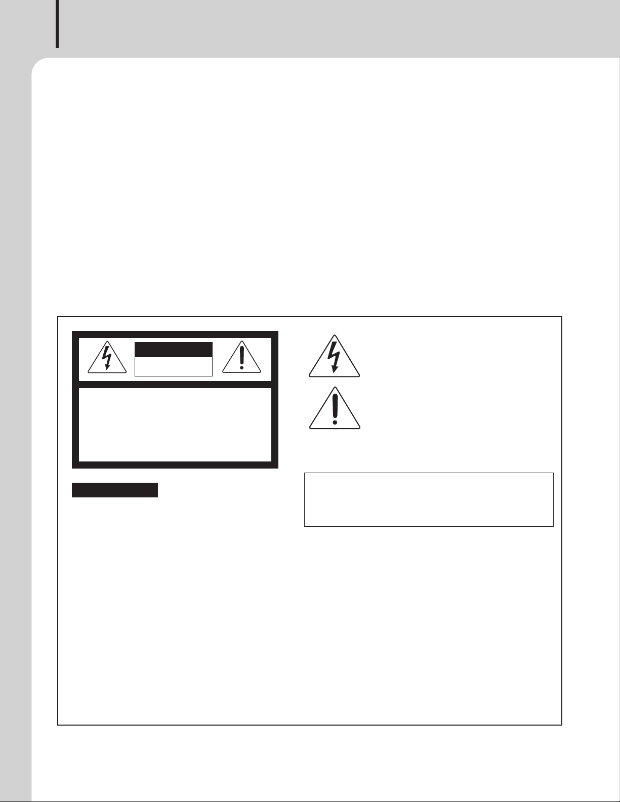
This symbol is intend ed to aler t the user to the
CAutION
RISK OF ELECTRIC SHOCK
DO NOT OPEN
CAUTION: TO REDUCE THE RISK OF ELECTRIC SHOCK.
DO NOT REMOVE COVER (OR BACK).
NO USER-SERVICEABLE PARTS INSIDE.
REFER SERVICING TO QUALIFIED SERVICE PERSONNEL.
Caution: To prevent electric shock do not use this (polarized) plug with
Attentions: Pour prévenir les chocs électriques ne pas utiliser cette
WARNING
To prevent fire or shock hazard, do not
expose the unit to rain or moisture.
*WARNING FOR YOUR PROTECTION PLEASE READ THE FOLLOWING-WATER AND MOISTURE: Unit should not be used near water(e.g.
near a bathtub, washbowl, kitchen sink, laundry tub, in a wet basement, or near a swimming pool, etc). Care should be taken so than objects do
not fall and liquids are not spilled into the enclosure through openings.
*Do not install this equipment in a confined space such as a book case or similar unit.
*This apparatus shall not be exposed to dripping or splashing and no objects filled with liquids, such vases, shall be placed on the apparatus.
*This apparatus shall be connected to a mains socket outlet with a protective earthing connection.
It has heed to be easy to disconnect the device. To disconnect the device from power, separate AC input cable from inlet or unplug the AC Cord.
*
*
The socket-outlet shall be installed near the equipment and shall be easily accessible.
CAutION
*These servicing instructions are for use by qualified service personnel only. To reduce the risk of electric shock, do not perform any servicing
other than that contained in the operating instructions unless you are qualified to do so.
NOtE
*This equipment has been tested and found to comply with the limits for a Class A digital device, pursuant to Part 15 of the FCC Rules. These limits are
designed to provide reasonable protection against harmful interference when the equipment is operated in a commercial environment. This equipment
generates, uses, and can radiate radio frequency energy and, if not installed and used in accordance with the instruction manual, may cause harmful
interference to radio communications. Operation of this equipment in a residential area is likely to cause harmful interference in which case the user will
be required to correct the interference at his own expense.
presence of uninsulated “dangerous voltage” within
the prod uct’s enclos ure t hat m ay be of suffi cient
magnitude to constitute a risk of electric shock to
persons.
This symbol is intend ed to aler t the user to the
presence of important operation and maintenance
(servicing) instructions in the literature accompanying
the appliance.
an extension cord, receptacle or other outlet unless the blades
can be fully inserted to prevent blade exposure.
fiche polarisée avec un prolongateur, une prise de courant
on une autre sortie de courant, sauf si les lames peuvent
étre insérées à fon d sa ns en laisser auc une par tie à
découvert.
Page 3

STEREO DOUBLE CASSETTE DECK
Contents
Contents
Unpacking .......................................................................................................................................2
Short Form Instructions .................................................................................................................2
Installation
Environment....................................................................................................................................3
Important Safety Instructions.............................................................................................................3
Description.......................................................................................................................................4
Features............................................................................................................................................4
Accessories.....................................................................................................................................4
Front Panel ......................................................................................................................................5
Rear Panel .......................................................................................................................................8
Connections.....................................................................................................................................9
Operation ......................................................................................................................................10
Play(Deck B only) ..........................................................................................................................10
Dubbing .......................................................................................................................................10
Recording.....................................................................................................................................11
Preventing Accidental Erasure ...................................................................................................12
Cassette Care and Handling ......................................................................................................12
Cassette Deck Maintenance........................................................................................................13
Applications ..................................................................................................................................14
Block Diagram ..............................................................................................................................15
Specifications ................................................................................................................................16
Service
Procedures....................................................................................................................................18
Schematic.....................................................................................................................................18
Parts List .......................................................................................................................................18
Variations and Options ...............................................................................................................18
Warranty .......................................................................................................................................18
PC-6335
1
Page 4

STEREO DOUBLE CASSETTE DECK
Unpacking
Unpacking
Please take a few minutes to read this manual to familiarize yourself with important information regarding
product features, and operation.
As with most electronic devices, ORIGINAL PACKAGING (OR EQUAL) IS REQUIRED in the unlikely event that
the product needs to be returned for servicing.
Short Form Instructions
Short Form Instructions
Preparing your PC-6335 for Recording or Playback in your system
1. Before switching on the AC mains power to the PC-6335, be sure to properly connect the input and output
signal cables to avoid pops and noise in your system (AC Mains will be connected at step 2 below). The PC6335 is equipped with one set of input connectors for stereo program material, as well as two separate sets
of output connectors. Connect the input connectors to the device from which you will record. Then determine
which set of outputs is best suited for your application. One set of outputs utilizes stereo RCA connectors and
has a variable output level, controlled by a potentiometer located on the front panel. The other output is
monaural and is fixed in level, with a single output connector. Connect the appropriate output(s) to the
input(s) of the device intended to receive the signal. If you are using the stereo output connections, be sure to
connect the Left and Right outputs of the PC-6335 to the Left and Right inputs of the device that follows in the
signal chain, in order to maintain the proper channel integrity of the stereo signal.
2. Connect the AC Mains power.
3. Make sure the input signal level control is at minimum (counterclockwise)
4. Make sure the Output level control is at minimum (counterclockwise) position if the stereo outputs are to be used.
5. Switch the AC mains power ON.
6. Depress the OPEN button to open the cassette door.
7. Load a Cassette into the player.
8. Close the Cassette Door.
9. Depress one of the PLAY buttons (◀) or (▶), to begin playback.
10. Slowly increase the output level to achieve the desired signal level (if the stereo output jacks are being used
in your system).
11. Depress the OPEN button to open the Deck B door.
12. Load a blank cassette into Deck B.
13. Close the Deck B door.
14. Position the MODE selector to record on one side or both sides of the cassette, as desired.
15. Press RECORD button.
16. Adjust RECORD LEVEL until -11dB LED indicator flashes (illuminates intermittently).
17. Press PLAY button to begin recording.
18. Press STOP button to end recording.
2
PC-6335
Page 5

STEREO DOUBLE CASSETTE DECK
S
3125A
Installation
Installation
Environment
Never place this product in an environment which could alter its performance or reduce its service life. Such
environments usually include high levels of heat, dust, moisture, and vibration.
IMPORTANT SAFETY INSTRUCTIONS
1. Read these instructions.
2. Keep these instructions.
3. Heed all warnings.
4. Follow all instructions.
5. Do not use this apparatus near water.
6. Clean only with dry cloth.
7. Do not block any ventilation openings. Install in accordance with the manufacturer’s instructions.
8. Do not install near any heat sources such as radiators, heat registers, stoves, or other apparatus (including
amplifiers) that produce heat.
9. Do not defeat the safety purpose of the polarized or grounding-type plug. A polarized plug has two blades
with one wider than the other. A grounding type plug has two blades and a third grounding prong. The wide
blade or the third prong are provided for your safety. If the provided plug does not fit into your outlet, consult
an electrician for replacement of the obsolete outlet.
10. Protect the power cord from being walked on or pinched particularly at plugs, convenience receptacles, and
the point where they exit from the apparatus.
11. Only use attachments/accessories specified by the manufacturer.
12. Use only with the cart, stand, tripod, bracket, or table specified by the manufacturer, or sold with the apparatus.
When a cart is used, use caution when moving the cart/apparatus combination to avoid injury from tip-over.
13. Unplug this apparatus during lightning storms or when unused for long periods of time.
14. Refer all servicing to qualified service personnel. Servicing is required when the
apparatus has been damaged in any way, such as power-supply cord or plug is
damaged, liquid has been spilled or objects have fallen into the apparatus, the
apparatus has been exposed to rain or moisture, does not operate normally, or has
been dropped.
S3125A
PC-6335
3
Page 6

STEREO DOUBLE CASSETTE DECK
Description
Description
The PC-6335 is a stereo double cassette player/recorder that requires 3U rack space for mounting.
Features
Features
- FULL LOGIC AUTO-REVERSE
Logic-controlled auto-reverse is provided for continuous playback.
- NORMAL SPEED SYNCHRO DUBBING
Synchro dubbing from Deck A to Deck B is available at normal speed.
- RESERVE TIMER
Automatically begins playing or recording when AC mains power is switched on.
- DIGI-LINK
Remote Control Compatible with the “Digi-link” control system only available in Korea (not used in other
countries). It uses PHILIPS-CODE.
Accessories
Detachable AC Mains Power Cable
2 Stereo RCA Cables
4
PC-6335
Page 7
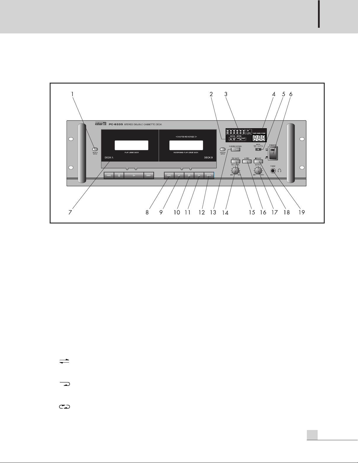
Front Panel
Front Panel
STEREO DOUBLE CASSETTE DECK
1. OPEN BUTTON
Press this button to open the corresponding cassette door.
NOTE: Caution : Cassette door will open if pressing “open” button even in playing, recording or copying
(dubbing) status. When cassette door is needed to open, press “stop” button and then press “open” button
2. DISPLAY LAMP
Display status of operation.
3. LEVEL METER
Displays the input signal level when recording, or the output signal level of a tape during playback.
4. TAPE DIRECTION
This indicates the play direction of tape.
5. MODE SELECTOR(DECK B ONLY)
This selector switch permits the selection of the desired mode of operation.
Single Side only Play Mode – Operation automatically stops at the end of one side of the cassette that
is playing.
Auto-Reverse Mode – Operation automatically stops at the end of both sides of the cassette that is
playing.
Continuous Play Mode – Operation automatically repeats Auto-Reverse mode of the cassette until
stopped manually.
PC-6335
5
Page 8

STEREO DOUBLE CASSETTE DECK
6. POWER SWITCH
he position of this switch determines whether the power is ON or OFF. The switch will illuminate to indicate
T
the power is ON.
7. CASSETTE DOOR
It opens and closes smoothly with gear damper.
8. REWIND BUTTON (◀◀)
Press this button to rewind the tape to left direction with high speed.
9. REVERSE BUTTON (◀)
Press to playback/record side one of the cassette. The direction of tape travel and Deck selection will be
indicated in the display screen.
10. STOP BUTTON (■)
Press this button to stop all functions.
11. FORWARD BUTTON (▶)
Press to play/record side one of the cassette. Deck A is capable of playback only, Deck B is capable of
playback or record. The direction of tape travel and Deck selection will be indicated in the display screen.
12. FAST-FORWARD BUTTON (▶▶)
Press this button to forward the tape to right direction with high speed.
13. DUBBING NORMAL
Select normal dubbing speed and initiate dubbing by depressing the corresponding button. The selected
normal dubbing speed will be indicated in the display screen.
14. RECORDING LEVEL CONTROL
This control determines the recording input signal level.
15. REC MUTE
Pressing this button will create a 4-second blank segment and then end the recording. Does not apply when
using the dubbing function.
16. REC BUTTON (●)
Press this button to prepare to record. The deck will remain in record-pause mode until the play button is
selected to begin the recording or the stop button is depressed to cancel the recording. The record indicator
in the display screen will indicate the record button has been depressed. Both tape direction indicators will
flash in the display screen while in the record-pause mode.
17. OUTPUT LEVEL
This control determines the output signal level of the Variable Output.
6
PC-6335
Page 9

STEREO DOUBLE CASSETTE DECK
18. PAUSE BUTTON ( II)
ressing the Pause button during playback or recording will temporarily stop the cassette tape. Both tape
P
direction indicators for the corresponding deck will flash in the display screen while in the pause mode.
Display blinks with showing “PAU”.
19. HEADPHONE JACK
This jack is for the connection of stereo headphones. The signal level (volume) is controlled by the output
signal level control.
PC-6335
7
Page 10

STEREO DOUBLE CASSETTE DECK
Rear Panel
Rear Panel
1. DC 24V
These terminals are for connecting 24V DC emergency power or DC mains. Observe proper polarity when
making connections.
2. RESERVE TIMER
Allows for unattended playback or recording on Deck B when power is restored to the unit. This slide switch
is used to select the desired mode of operation.
PLAY position: The unit will begin playing a cassette tape when AC mains power is applied to the AC input.
RECORD position:
OFF position: The unit will be in the stop mode when AC mains power is applied to the AC input.
3. AC MAINS POWER INPUT
Connect the supplied AC Mains power cord here.
4. MONO OUTPUT (FIXED)
1/4” jack connector for a mono line level output that is not affected by the Output Level control.
5. STEREO OUTPUT (VARIABLE)
Dual-RCA connectors for a stereo line level output. The output signal level (volume) is determined by the front
panel Output Level control.
6. LINE IN
Dual-RCA stereo connectors for line-level input signals for recording.
The unit will begin recording onto a cassette tape when AC mains power is applied to the AC
input.
7. DIGI-LINK
8
Connector for use with other DIGI-LINK compatible equipment available in Korea.
PC-6335
Page 11

STEREO DOUBLE CASSETTE DECK
Signal
G
round
Tip
Sleeve
UNBALANCED MONO OUTPUT(1/4˝ Jack)
Tip
Sleeve
STEREO INPUT/OUTPUT(RCA Jack)
Connections
Connections
Inter-M products are wired to reflect accepted wiring practices used throughout the world.
Connect the outputs to an appropriate device. Common and standard rules of interconnect apply, including the
ability to split output signals but not combine two signals to one input.
Unbalanced RCA and 1/4” jack connectors are wired as described:
Tip is Positive
Sleeve is Common
Connecting the Output Terminals
Connect one end of the cable supplied with the Cassette Deck to the output terminals, left (L) and right (R) of the
Cassette Deck, and the other end to the TAPE PLAY input terminals, left (L) and right (R), of the mixer or other
suitable device.
Connecting the Input Terminals
Connect one end of the cable supplied with the Cassette Deck to the input terminals, left (L) and right (R) of the
Cassette Deck, and the other end to the TAPE REC output terminals, left (L) and right (R), of the mixer or other
suitable device.
Make a connection to only ‘L/MONO’ input for voice recording.
PC-6335
9
Page 12

STEREO DOUBLE CASSETTE DECK
Operation
Operation
Digilink function
1. Only use Inter-M system of DIGILINK CONTROL. (The Device use Philips code)
Play(Deck B only)
1. Choose one of the three play modes with the Play Mode Selector buttons
Single Side only Play Mode – Operation automatically stops at the end of
one side of one cassette.
Auto-Reverse Mode - Operation automatically stops at the end of both sides of one cassette.
Continuous Play Mode - Operation automatically repeats Auto-Reverse mode of one cassette until
stopped manually.
2. Switch the AC mains power on.
3. Press OPEN Button to open cassette door of Deck B.
4. Insert tape to be played into Deck B.
5. Close Deck B cassette door.
6. Press Play Button on Deck B.
Dubbing (copying tapes)
1. Set Play Mode Selector to desired position.
2. Switch the AC mains power on.
3. Insert the cassette to be copied into Deck A.
4. Insert the cassette onto which you wish to dub (record) into Deck B.
5. Press the Dubbing button.
6. Press Stop button to end dubbing.
10
PC-6335
Page 13

STEREO DOUBLE CASSETTE DECK
Recording
1. Set Play Mode Selector to desired position.
2. Switch the AC mains power on.
3. Press the OPEN button to open the Deck B cassette door.
4. Load a blank cassette into Deck B with the side to be recorded facing outward.
5. Close cassette door.
6. Position the MODE selector to record on one side or both sides of the cassette, as desired.
7. Press REC Button.
8. Adjust RECORD LEVEL until -11dB mark illuminates (flashes) intermittently.
9. Position the MODE selector to record on one side or both sides of the cassette, as desired.
10. Press PLAY button to begin recording.
11. Press STOP button to end recording.
PC-6335
11
Page 14

STEREO DOUBLE CASSETTE DECK
Preventing Accidental Erasure
Preventing Accidental Erasure
You can prevent cassette tapes from accidental erasure by removing the tab on the top of the cassette shell.
Remove tab on top of tape to avoid
accidental erasure
To record on a cassette after the tab has been removed,
cover opening with cellophane tape.
Cassette Care and Handling
Cassette Care and Handling
1. Keep a cassette in its case when not in use.
2. Cassette tapes should be kept away from sources of magnetism such as speakers or television sets.
3. Do not touch the exposed portion of the cassette tape.
4. Keep cassette tapes out of direct sunlight.
12
PC-6335
Page 15

STEREO DOUBLE CASSETTE DECK
Cassette Deck Maintenance
Cassette Deck Maintenance
After every 10 hours of use of the cassette deck, the tape heads should be cleaned to help maintain the best
possible sound quality.
Record/Play Head
Clean Tape Head with a cotton
swab moistened with alcohol or a
commercial head cleaner
PC-6335
13
Page 16

STEREO DOUBLE CASSETTE DECK
Applications
Applications
14
PC-6335
Page 17

Block Diagram
Block Diagram
STEREO DOUBLE CASSETTE DECK
PC-6335
15
Page 18

STEREO DOUBLE CASSETTE DECK
Specifications
Specifications
PC-6335
Type Auto-Reverse double cassette deck with operating controls
Track System 4-track 2-channel Stereo play (deck A) & record/play (deck B)
Record and Erase System AC Bias System (Bias Frequency: 85 kHz)
Tape Speed 4.76cm/sec (Playback/Record)
Head DECK A: One Way head (Play head x1)
DECK B: Rotating reverse head (Rec/play head x 1), (Erase head x 1)
Motor High torque DC motor
Wow and Flutter Less than 0.4% (JIS WTD) WRMS
Fast Winding Time 100 sec (±) 5 sec. (C-60 TAPE)
Frequency Response (±3dB) 125Hz/1kHz/6.3kHz, Normal Tape
Signal to Noise(S/N) Over than 40dB
Input Sensitivity/Impedance 160mV/10kΩ
Output Level/Impedance 600mV/600Ω
Erase Ratio 43dB
Operating Temperature -10°C ~ 40°C / 14°F ~ 104°F
Power Source 100-120VAC or 220V-240VAC; 50/60Hz, 24V DC
(Supplied AC mains transformer depends on country requirements)
Power Consumption 20W
Weight (SET) 5.8kg/12.8lb
Dimensions (SET) 482(W)x132(H)x280(D)mm/19(W)x5.2(H)x11(D)in
* Specifications and design are subject to change without notice.
16
PC-6335
Page 19

※ DIMENSIONS
440
280
132
482
STEREO DOUBLE CASSETTE DECK
PC-6335
17
Page 20

STEREO DOUBLE CASSETTE DECK
Service
Service
Procedures
Take steps to insure the problem is not related to operator error or other products within the system. Information
provided in the troubleshooting portion of this manual may help with this process. Once it is certain that the
problem is related to the product contact your warranty provider as described in the warranty section of this
manual.
Schematic
A Schematic is available by contacting your warranty provider.
Parts List
A Parts List is available by contacting your warranty provider.
Variations and Options
Variations and Options
Variations
Products supplied through legitimate sources are compatible with local AC power requirements.
Options
No optional items are available for this product.
Warranty
Warranty
Warranty terms and conditions vary by country and may not be the same for all products. Terms and conditions
of warranty for a given product may be determined first by locating the appropriate country which the product
was purchased in, then by locating the product type.
To obtain specific warranty information and available service locations contact Inter-M directly or the
authorized Inter-M Distributor for your specific country or region.
18
PC-6335
Page 21

NOTE
PC-6335
3
Page 22

NOTE
2
PC-6335
Page 23

PC-6335
3
Page 24

Inter-M, Ltd. (Korea) began operations in 1983.
Since then, Inter-M has grown to become one of the largest manufacturers
of professional audio and commercial sound electronics equipment in the world.
Inter-M has gained worldwide recognition for its own branded products,
as well as private label manufacturing of electronics sold under other names (OEM).
The company is no longer just a Korean company, but rather a global company
that is truly international in scope, with factories and offices in Korea and China,
and sales and marketing operations located in Japan, Europe, and the U.S.A.
With more than 850 employees around the globe,
Inter-M is well-poised for further growth and expansion.
Inter-M Americas, Inc.
13875 Artesia Blvd. Cerritos, CA 90703 USA
TEL : +1-562-921-0313, FAX : +1-562-921-0370
Home Page : http://www.inter-m.net, E-mail : info@inter-m.net
Inter-M Corporation
Seoul OFFICE : 653-5 BANGHAK-DONG, DOBONG-KU, SEOUL, KOREA
TEL : +82-2-2289-8140~8, FAX : +82-2-2289-8149
Home Page : http://www.inter-m.com, E-mail : overseas@inter-m.com
MADE IN KOREA
June 2012 130441
 Loading...