

Page 1

Operation Manual
Modular Digital Amplifier
A-500
* Rack mount products in the Western Hemisphere(North America, South America, and the Caribbean)
do not have handles installed due to customer preference.
Page 2
MODULAR DIGITAL AMPLIFIER
Welcome
Welcome
A personal welcome to you from the management and employees of Inter-M
All of the co-workers here at Inter-M are dedicated to providing excellent products with inherently good value,
and we are delighted you have purchased one of our products.
We sincerely trust this product will provide years of satisfactory service, but if anything is not to your complete
satisfaction, we will endeavor to make things right.
Welcome to Inter-M, and thank you for becoming part of our worldwide extended family!
RISK OF ELECTRIC SHOCK
DO NOT OPEN
CAUTION
CAUTION: TO REDUCE THE RISK OF ELECTRIC SHOCK.
DO NOT REMOVE COVER (OR BACK).
NO USER-SERVICEABLE PARTS INSIDE.
REFER SERVICING TO QUALIFIED SERVICE PERSONNEL.
WARNING
To prevent fire or shock hazard, do not
expose the unit to rain or moisture.
*WARNING FOR YOUR PROTECTION PLEASE READ THE FOLLOWING-WATER AND MOISTURE: Unit should not be used near water(e.g.
near a bathtub, washbowl, kitchen sink, laundry tub, in a wet basement, or near a swimming pool, etc). Care should be taken so than objects do
not fall and liquids are not spilled into the enclosure through openings.
*CLASS 2 WIRING (Adjacent to speaker terminal): The speaker output of this apparatus can exceed 10 Watts and could be a shock injury.
Connection to speakers should be performed by a skilled person.
*Do not install this equipment in a confined space such as a book case or similar unit.
*This apparatus shall not be exposed to dripping or splashing and no objects filled with liquids, such vases, shall be placed on the apparatus.
*This apparatus shall be connected to a mains socket outlet with a protective earthing connection.
*
It has heed to be easy to disconnect the device. To disconnect the device from power, separate AC input cable from inlet or unplug the AC Cord.
CAUTION
*These servicing instructions are for use by qualified service personnel only. To reduce the risk of electric shock, do not perform any servicing
other than that contained in the operating instructions unless you are qualified to do so."
NOTE
*This equipment has been tested and found to comply with the limits for a Class A digital device, pursuant to Part 15 of the FCC Rules. These limits are
designed to provide reasonable protection against harmful interference when the equipment is operated in a commercial environment. This equipment
generates, uses, and can radiate radio frequency energy and, if not installed and used in accordance with the instruction manual, may cause harmful
interference to radio communications. Operation of this equipment in a residential area is likely to cause harmful interference in which case the user will
be required to correct the interference at his own expense.
This symbol is intended to alert the user to the
presence of uninsulated “dangerous voltage” within
the product’s enclosure that may be of sufficient
magnitude to constitute a risk of electric shock to
persons.
This symbol is intended to alert the user to the
presence of important operation and maintenance
(servicing) instructions in the literature accompanying
the appliance.
Caution: To prevent electric shock do not use this (polarized) plug with
an extension cord, receptacle or other outlet unless the blades
can be fully inserted to prevent blade exposure.
Attentions: Pour prévenir les chocs électriques ne pas utiliser cette
fiche polarisée avec un prolongateur, une prise de courant
on une autre sortie de courant, sauf si les lames peuvent
étre insérées à fond sans en laisser aucune partie à
découvert.
Page 3

MODULAR DIGITAL AMPLIFIER
1
A-500
Contents
Contents
Unpacking .......................................................................................................................................2
Installation
Environment....................................................................................................................................2
Important Safety Instructions.............................................................................................................2
Features............................................................................................................................................3
Front Panel ......................................................................................................................................4
Rear Panel .......................................................................................................................................6
Applications ....................................................................................................................................8
Block Diagram ................................................................................................................................9
Specifications ................................................................................................................................10
Service
Procedures....................................................................................................................................11
Schematic.....................................................................................................................................11
Parts List .......................................................................................................................................11
Variations and Options ...............................................................................................................11
Warranty .......................................................................................................................................11
Page 4

MODULAR DIGITAL AMPLIFIER
Unpacking
2
A-500
Unpacking
Although your A-500 is neither complicated nor difficult to operate, we recommend you take a few minutes to
read this brief manual and familiarize yourself with the important information regarding product features, setup
and operation.
As with most electronic devices, we strongly recommend you retain the original packaging. In the unlikely event
the product must be returned for servicing, the original packaging (or reasonable equivalent) is required.
Installation
Installation
Environment
Never place this product in an environment which could alter its performance or reduce its service life. Such
environments usually include high levels of heat, dust, moisture, and vibration.
IMPORTANT SAFETY INSTRUCTIONS
1. Read these instructions.
2. Keep these instructions.
3. Heed all warnings.
4. Follow all instructions.
5. Do not use this apparatus near water.
6. Clean only with dry cloth.
7. Do not block any ventilation openings. Install in accordance with the manufacturer’s instructions.
8. Do not install near any heat sources such as radiators, heat registers, stoves, or other apparatus (including
amplifiers) that produce heat.
9. Do not defeat the safety purpose of the polarized or grounding-type plug. A polarized plug has two blades
with one wider than the other. A grounding type plug has two blades and a third grounding prong. The wide
blade or the third prong are provided for your safety. If the provided plug does not fit into your outlet, consult
an electrician for replacement of the obsolete outlet.
10. Protect the power cord from being walked on or pinched particularly at plugs, convenience receptacles, and
the point where they exit from the apparatus.
11. Only use attachments/accessories specified by the manufacturer.
12. Use only with the cart, stand, tripod, bracket, or table specified by the manufacturer, or sold with the apparatus.
When a cart is used, use caution when moving the cart/apparatus combination to avoid injury from tip-over.
13. Unplug this apparatus during lightning storms or when unused for long periods of time.
14. Refer all servicing to qualified service personnel. Servicing is required when the
apparatus has been damaged in any way, such as power-supply cord or plug is
damaged, liquid has been spilled or objects have fallen into the apparatus, the
apparatus has been exposed to rain or moisture, does not operate normally, or has
been dropped.
S3125A
S3125A
Page 5

MODULAR DIGITAL AMPLIFIER
3
A-500
Features
Features
- Adoption of high efficiency full digital AMP
- 30W /ch (output voltage 100V, 333Ω or 70V, 163Ω) / 7-Ch modular AMP
- Built-in 1-Ch spare AMP (automatic conversion)
- Monitoring function (use of headphone)
- Signal LED and protective LED
- Built-in of various protective function (OCP, OTW, OVP, UVP)
- Adoption of stable SMPS (switching mode power supply)
- Operation of DC 24V battery power during emergency
Page 6
MODULAR DIGITAL AMPLIFIER
4
A-500
Front Panel
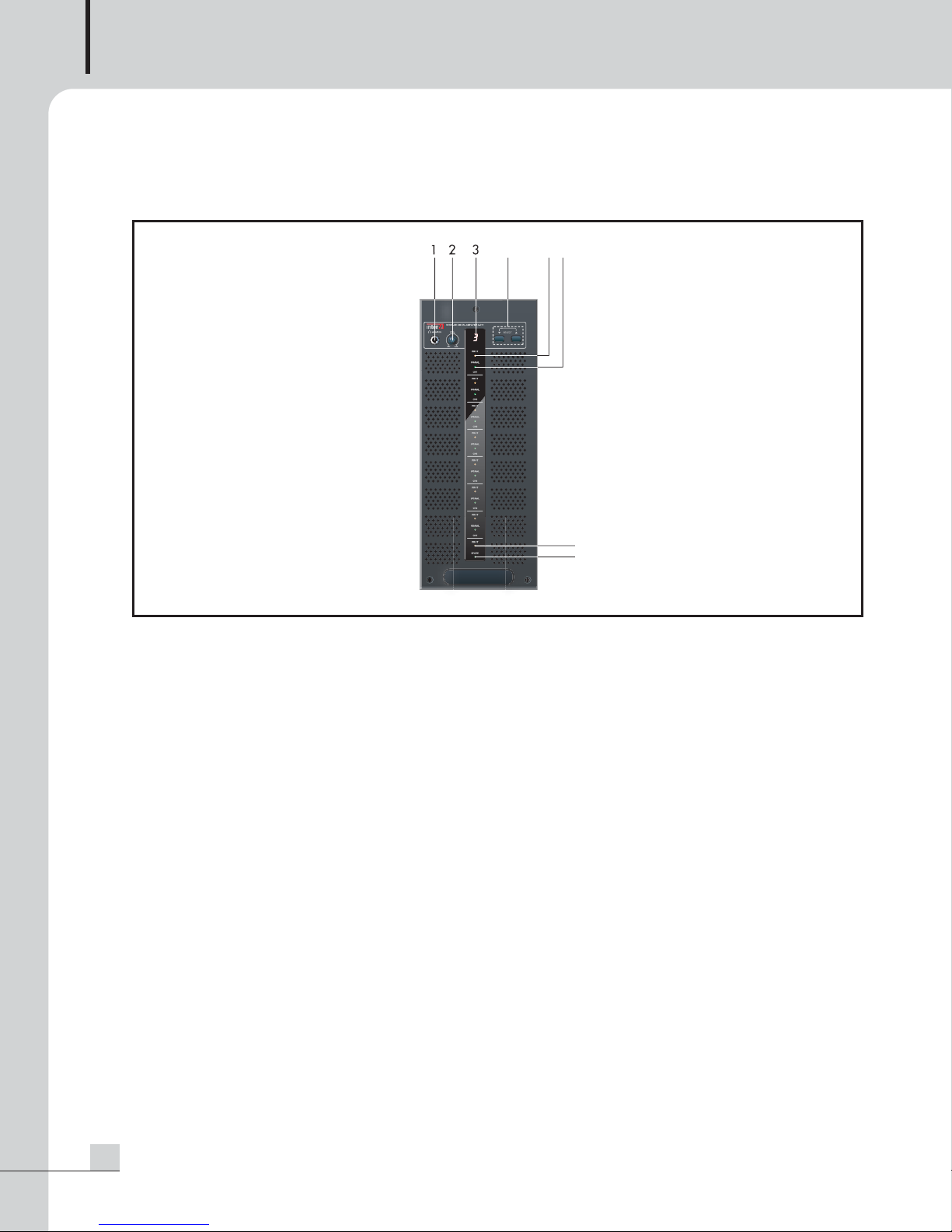
Front Panel
1. MONITOR OUTPUT JACK
This is a jack to monitor by inserting a headphone and headphone with diameter of 6.3mm Jack can be
used. Mono signal is output.
2. MONITOR VOLUME
This is a volume to control sound volume when monitoring signal supplied to AMP from Z-500.
Slowly turn the volume to the right for appropriate sound volume with the volume at Min (turn left) for the first
time since too large sound may damage to your hearing.
3. MONITOR CHANNEL DISPLAY
This is a display to indicate the selected channel and shows #1~#7.
4. MONITOR CHANNEL DOWN/UP SWITCH
This is a switch to select and monitor channel of signals supplied from Z-500 and DOWN/UP operation is
performed within #1-ch~#7-ch whenever pressing it once.
5. Protective LED
The red lamp turns on if inner protective circuit operates due to abnormal operation generates at AMP, to inform
warn of failure status. #1 ~ #7 channel individually operates depending on failure of the relevant channel.
In this case, check of failure of the AMP or short-circuit of a speaker and then take a measure to prevent any
failure before use.
6. SIGNAL LED DISPLAY
This is a signal LED to display signal level input from Z-500. The green lamp turns on when signal level input
is about more than -30dBv. LED of #1~#7channel operates depending on signal level.
7
8
4
5
6
Page 7

MODULAR DIGITAL AMPLIFIER
5
A-500
7. SPARE AMP PROTECTIVE LED
The red LED turns on in generation of failure in the spare AMP channel.
If there is failure in other channels due to occurrence of problems in the spare AMP, normal broadcasting is
not done even after automatic conversion.
8. SPARE AMP LED
The red LED turns on when the spare AMP operates.
The red LED turns on to display that the spare AMP operates after signal is automatically converted to spare
AMP when the self-temperature detection circuit and the over-current protection circuit of 7-ch of AMP
operate for any reason,
Page 8

MODULAR DIGITAL AMPLIFIER
6
A-500
Rear Panel
Rear Panel
1. AC POWER INPUT TERMINAL
Use power connection cords included in the set.
Supplied AC main power depends on contry requirement.
2. POWER SWITCH
This is a switch of a structure that AC power supply is turned on or off with one pole during power Off.
DC is not shut out by turning this switch off.
3. DC 24V INPUT TERMINAL
This is a terminal to connect battery power for emergency operation. If AC power as commercial power is
shut off with battery power connected, operation is done by automatically using battery power.
4. SIGNAL INPUT CONNECTOR
This is a connector where 7-ch analog signals are input from Z-500.
Use 25P 600mm cables provided as accessories to the set during connection.
3
2
1
4
5
6
13 12 11 10 9 8 7 6 5 4 3 2
25 24 23 22 21 20 19 18 17 16 15 14
1
Page 9

MODULAR DIGITAL AMPLIFIER
7
A-500
5. DC FAN
This is a DC fan that micro-process measures inner temperature of the set for operation, and operates 3-step
of speed: OFF, LOW, HIGH.
6. SPEAKER TERMINAL
Connect output contactor appropriate for channel before use by referring to printing specifications. Use 2pcs
of 9P terminal blocks provided as accessories of the set during connection of speaker wires. A small (-) driver
with diameter of about 3mm is required.
Pin 1 2 3 4 5 6 7 8 9
Purpose CH1+ GND CH2- CH3+ GND CH4- CH5+ GND CH6-
Pin 10 11 12 13 14 15 16 17 18
Purpose CH7+ GND NC NC CH1- CH2+ GND CH3- CH4+
Pin 19 20 21 22 23 24 25
Purpose GND CH5- CH6+ GND CH7-
Fault Signal
NC
Page 10

MODULAR DIGITAL AMPLIFIER
8
A-500
Applications
Applications
Page 11

MODULAR DIGITAL AMPLIFIER
9
A-500
Block Diagram
Block Diagram
CH 1 OUTPUT
CH 2 OUTPUT
OPT
24V24V24V24V
LPF
P 1
D-AM
DATA 1,2
OPT
LPF
P 2
D-AM
CH 3 OUTPUT
OPT
LPF
P 3
D-AM
DATA 3,4
CH 4 OUTPUT
CH 5 OUTPUT
OPT
OPT
24V
LPF
P 4
D-AM
P 5
D-AM
DIGITAL SIGNAL
PROCESSOR
TAS5518
DATA 5,6
CH 6 OUTPUT
OPT
24V24V
LPF
LPF
P 6
D-AM
CH 7 OUTPUT
AMP
LPF
OPT
24V
LPF
LPF
P 7
P S
D-AM
D-AM
MCLK
DATA 7
BCK
LRCLK
AMP
LPF
SPARE-AMP
13.5MHz
CH-1
LEDs
SMPS BLOCK
ENCODER
CH-2
CH-3
CH-4
SMPS
GND
5V DC
+29V DC
MONITORING
FRONT BLOCK
CH-5
CH-6
CH-7
SPARE
SIGNAL LEDs
PROTECTION
From Battery
AC INLET
DC INPUT
D/D CON.
C
GND
+24V D
10MHz
A/D
ADC AK5384
2
2
x 2
BUFFER AMP
2
BUFFER AMP
A/D
2
x 2
7ch Balanced input
2
BUFFER AMP
A/D
2
x 2
MICRO CONTROLLER
12.288MHz
A/D
1
1
BUFFER AMP
MODULE - 3
ANALOG SIGNAL INPUT
INPUT
CONNECTOR
MODULE - 2
MODULE - 1
Page 12

MODULAR DIGITAL AMPLIFIER
10
A-500
A-500
Output channel 7channel + 1channel(spare channel)
Rated Output(at THD 1%) 30W/channel (Total : 210W)
Input sensitivity 0dBV Balanced
Signal to Noise More 80dB
Total Harmonic Distribution(THD) Under 0.1% ( AES_17 Filter)
Frequency Response 100Hz~20kHz( 3dB) at 36V
Power source AC 100-120V or 220-240V, 50/60Hz ; DC 24V
Operating temperature -10°C ~ 40°C
Operating humidity 0% ~ 90%
Power consumption 70W(1/8 Output)
Weight (module) 8.9kg /19.6lb (Module)
Dimensions (module) 124(W) x 310(H) x 380(D)mm/4.9(W)x12.2(H)x15(D)in
* Specifications and design are subject to change without notice.
Specifications
Specifications
Page 13

MODULAR DIGITAL AMPLIFIER
11
A-500
Service
Service
Procedures
Take steps to insure the problem is not related to operator error or other products within the system. Information
provided in the troubleshooting portion of this manual may help with this process. Once it is certain that the
problem is related to the product contact your warranty provider as described in the warranty section of this
manual.
Schematic
A Schematic is available by contacting your warranty provider.
Parts List
A Parts List is available by contacting your warranty provider.
Warranty
Warranty
Warranty terms and conditions vary by country and may not be the same for all products. Terms and conditions
of warranty for a given product may be determined first by locating the appropriate country which the product
was purchased in, then by locating the product type.
To obtain specific warranty information and available service locations contact Inter-M directly or the
authorized Inter-M Distributor for your specific country or region.
Variations and Options
Variations and Options
Variations
Variations of this product exist to reflect the variations in AC power requirements throughout the world. Product
supplied through local sources are compatible with local AC power requirements.
Options
No optional items are available for this product.
Page 14

NOTE
Page 15

NOTE
Page 16

MADE IN KOREA
December 2008
Inter-M, Ltd. (Korea) began operations in 1983.
Since then, Inter-M has grown to become one of the largest manufacturers
of professional audio and commercial sound electronics equipment in the world.
Inter-M has gained worldwide recognition for its own branded products,
as well as private label manufacturing of electronics sold under other names (OEM).
The company is no longer just a Korean company, but rather a global company
that is truly international in scope, with factories and offices in Korea and China,
and sales and marketing operations located in Japan, Europe, and the U.S.A.
With more than 850 employees around the globe,
Inter-M is well-poised for further growth and expansion.
Inter-M Americas, Inc.
13875 Artesia Blvd. Cerritos, CA 90703 USA
TEL : +1-562-921-0313, FAX : +1-562-921-0370
Home Page : http://www.inter-m.net, E-mail : info@inter-m.net
Inter-M Corporation
Seoul OFFICE:653-5 BANGHAK-DONG, DOBONG-KU, SEOUL, KOREA
TEL : +82-2-2289-8140~8, FAX : +82-2-2289-8149
Home Page : http://www.inter-m.com, E-mail : overseas@inter-m.com
 Loading...