

Page 1

UltraView UVC-6130-1
WDR Box Camera User
Manual
P/N 1072547C • ISS 27JUL12
Page 2
Copyright
©
2012 UTC Fire & Security. All rights reserved.
Trademarks and
patents
The
UTC
Other trade names used in this document may be trademarks or
registered trademarks of the manufacturers or vendors of the
respective products.
Manufacturer
UTC Fire & Security Americas Corporation, Inc.
2955 Red Hill Avenue, Costa Mesa, CA 92626
Authorized EU manufacturing representative:
UTC Fire & Security B.V.
Kelvinstraat 7, 6003 DH Weert, The Netherlands
Certification
FCC compliance
Class A:
the limits for a Class A digital device, pursuant to part 15 of the FCC
Rules. These limits are designed to provide reasonable protection
against harmful interference when the equipment is operated i
commercial environment. This equipment generates, uses, and can
radiate radio frequency energy and, if not installed and used in
accordance with the instruction m anual, m a y cause harm f ul
interference to radio communications. Operation of this equipment in
a residential area is likely to cause harmful interference in which
case the user will be required to correct the interference at his own
expense.
Notice!
product may cause
required to take adequate measures.
European Union
directives
12004/108/EC (EMC directive):
declares that this device is in compliance or with the essential
requirements and ot
2002/96/EC (WEEE directive):
cannot be disposed of as unsorted municip al was te in the Europ ean
Union. For proper recycling, return this product to your local supplier
upo
designated collection points. For more information see:
www.recyclethis.info.
Contact information
For contact information
www.utcfssecurityproducts.eu
UltraView and Interlogix names and logo are trademarks of
Fire & Security.
-5923, USA
N4131
This equipment has been tested and found to comply with
n a
ACMA compliance
This is a Class A product. In a domestic environment this
radio interference in which case the user may be
Hereby, UTC Fire & Security
her relevant provisions of Directive 2004/108/EC
Products marked with this symbol
n the purchase of equivalent new equipment, or dispose of it at
, see www.utcfireandsecurity.com or
.
Page 3

Content
Product overview 2
Package Contents 2
Features 2
User guidelines 2
Product description 3
OSD control pad 4
Installation 5
Connect the video cable 5
Attach the lens 5
Connect the power cable 6
Programming 8
Access the Setup menu 8
Select the lens type 9
Set shutter/AGC 9
Adjust the picture characteristics 11
Set white balance 11
Set WDR 12
Set image noise reduction 13
Set HLC and BLC 13
Set Day/Night mode 14
Set E-zoom 15
Set DIS 15
Set the privacy mask area 15
Set motion detection 16
Display the synchronization mode 16
Set the camera ID 17
Select the language 17
Reset camera settings 17
Save changes 18
Specifications 18
Dimensions 19
Menu Map 20
UltraView UVC-6130-1 WDR Box Camera User Manual 1
Page 4

Product overview
The UVC-6130-1- XX color video camera uses a digital signal processor (DSP)
to process video signals. The video camera includes a microcontroller to provide
high-quality images with high-color reproduction and sharp pictures.
Package Contents
The package contains the fol l owing:
• Box camera
• Dual power terminal block with screw and anchor
• Hex wrench
Features
The camera includes the following features:
• Super HAD II (hole accumulated diode) technology with 480,000 pixels NTSC
(570,000 PAL)
• LSI (large scale integration) digital processors, producing 650 lines o f
horizontal resolution
• Smart digital control automatic BLC (backlight compensation)
• WDR ( wide dynamic range)
• Advanced auto exposure system for both fixed iris and auto iris lenses to
optimize the amount of light
• Internal synchronization
• Eight privacy mask areas to protect privacy concerns
• Advanced OSD (onscreen di spl ay) control
• Signal-to-noise ratio better than 52 dB
• Long life and high reliability
• Isolated switching power 12 VDC or 24 VAC / full range 96VAC~240VAC for
UVC-6130-1-P2 camera
User guidelines
• Program the camera settings as much as possible before mounting the
camera. Take appropriate safety precautions while completing programming
after installation.
• Always use a 12 VDC or 24 VAC UL listed Class 2 power supply to power the
camera.
• Do not use the camera over the temperature range specifications: -10°C to
+50°C (14°F to 122°F)
2 UltraView UVC-6130-1 WDR Box Camera User Manual
Page 5

1. Video output
3. OSD control pad
4. D/N trigger pin
1. Video output
3. OSD control pad
4. D/N trigger pin
• If the light source where the camera is installed experiences rapid, widevariations in lighting, the camera may not operate as intended.
WARNING: To reduce the risk of fire or electronic shock, do not expose the
camera to rain or moisture and do not remove the cover or back.
Product description
Figure 1: Camera UVC-6130-1-P/N
2. Audio output
Figure 2: Camera UVC-6130-1-P2
5. 12 VDC / 24 VAC dual power
2. Audio output
UltraView UVC-6130-1 WDR Box Camera User Manual 3
5. AC96V/AC240 universal power
Page 6

Pad
Up
Left
Right
Down
Enter
OSD control pad
The on-screen display (OSD) control pad (see Figure 1) lets you manually control
the camera functions. Table 1 below lists the OSD control pad functions and
describes their use.
Table 1 Using the OSD control pad
direction Description
Moves the cursor upward to select an item
Moves the cursor left to select or adjust the parameters of the selected
item.
Moves the cursor to the right to select or adjust the parameters of the
selected item.
Moves the cursor downward to select an item.
Press the center of the control pad to display the Main menu. If the
selected item has its own menu, press the pad to enter a submenu.
4 UltraView UVC-6130-1 WDR Box Camera User Manual
Page 7
Installation
Please check the package contents and make sure that the device in the
package is in good condition and all the assembly parts are included.
To install the camera you will need to prepare the mounting surface, mount the
camera, attach the lens, and make cable connections,
Note: Before installing, please ensure that the mounting surface is strong enough
to withstand three times the weight of the camera. If the mounting surface is not
strong enough, the camera may fall and cause serious damage.
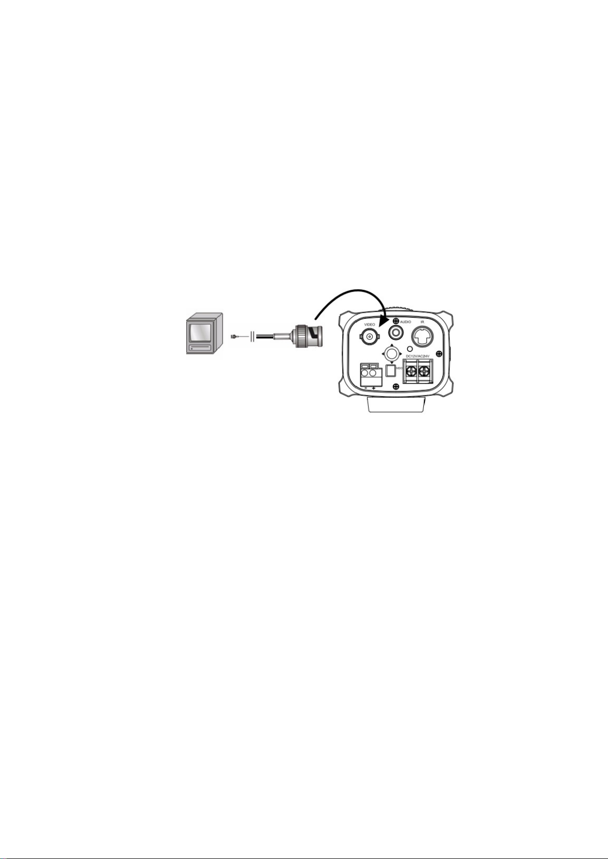
Connect the video cable
Connect a coaxial cable from the camera’s BNC connector to a CCTV monitor or
video recording device.
Attach the lens
Refer to the instructions that came with the lens you purchased for complete
installation instructions of that lens.
Note: For optimal perfor ma nce, us e an aut o i r i s lens.
UltraView UVC-6130-1 WDR Box Camera User Manual 5
Page 8

1. Camera
3. Lens (autoiris shown)
4. DC type autoiris lens leads
C Driving coil (+); D Driving coil (-)
Figure 3: Attaching the lens
2. Autoiris lens plug
A. Damping coil (+); B. Damping coil (-);
To attach the lens:
1. Screw the lens clockwise onto the lens mount of the camera.
Note: Please prevent dust from entering between the lens mount and the
lens.
2. For optimal performance, please use an auto iris lens. Plug the auto-iris drive
cable to the 4-pin interface on the side of the camera.
Connect the pow er cable
For UVC-6130-1-P/N:
1. With a screwdriver, loosen the ~AC24V/DC12V and GND terminal screws on
the terminal block.
2. Connect a universal 12 VDC/24 VAC power supply to the terminal block.
Note: The terminal block is not polarity sensitive. Either power lead can be
connected to either terminal connector. There is no need for an isolated
ground wire. The two power terminals can accept any polarity and any
combination of power that equals 12 VDC or 24 VDC.
3. Retighten the terminal screws until snug, ensuring that the power leads are
secure.
4. Supply power to the unit by plugging the power supply into a proper source.
Note: The power LED illuminates to show that the camera is receiving power.
If it does not illuminate, check the terminal block connections and the power
source.
6 UltraView UVC-6130-1 WDR Box Camera User Manual
Page 9

For UVC-6130-1-P2:
Connect the power cable of a high voltage camera to either a 230 VAC or a 120
VAC power supply outlet.
UltraView UVC-6130-1 WDR Box Camera User Manual 7
Page 10

Programming
Once the camera hardware has been installed, the camera can then be
configured.
Access the Setup menu
The Setup menu provides access to the camera configuration options. The onscreen display (OSD) is only available in English.
Program the camera by attaching a standard video monitor to the system.
Figure 4: The Setup menu
Table 2: Setup menu description
Menu item Description
Lens Defines the lens type as manual or autoiris.
Shutter/AGC Defines the method of light control.
Pict Adjust Defines the image quality functions.
White Bal Defines the white balance (WB) set up.
WDR Defines the wide dynamic range (WDR) set up.
NR Defines the digital noise reduction level.
BLC/HLC Defines the highlight compensation (HLC) and backlight compensation
(BLC) set up.
Day/Night Defines the day/night (D/N) set up.
EZoom Enables/disables digita l zoom.
DIS Enables/disables the digital image stabilizer.
Privacy Defines privacy mask set up.
Motion Det Defines the motion detection set up.
Sync Displays the current synchronization mode.
Camera ID Defines the camera ID displayed on-screen.
Language Defines the language of the OSD.
Camera Reset Resets the camera to factory default settings.
Exit & save Exits the menu and returns to live mode. Saves changes made.
8 UltraView UVC-6130-1 WDR Box Camera User Manual
Page 11

To access the Setup menu:
1. Press the OSD control pad (Enter) to access the Main menu and its
submenus.
2. Push the pad up, down, left and right to move betw een me nu opti o ns.
3. Press the OSD control pad to select an option.
4. W hen in a sub menu, select Return to return to the previous menu.
5. To exit the Main menu, move the cursor to Exit at the bottom of the screen
and press Enter. All changes are saved.
Select the lens type
In the Setup menu, go to Lens and select the type of lens used with the camera,
Auto or Manual. Select Manual for a manual lens and adjust the options
manually, or select Auto to set the lens type to autoiris. The Autoiris menu
appears.
Autoiris menu:
Type: Select the drive mode of the lens. Only DC is available.
Mode: Select the iris control mode. Auto (automatically controlled depending on
the light), Open (always open), or Closed (always closed).
Speed: When the mode is set to Auto, select the convergence speed of the iris
between 0 and 255.
Set shutter/AGC
In the Setup menu, go to Shutter/AGC and select the required light control
option: Manual, Auto or Traffic. Aut o is default. The selected me nu a ppe ar s :
UltraView UVC-6130-1 WDR Box Camera User Manual 9
Page 12

Automatic shutter menu:
Select the parameters for high and low luminance conditions:
High Luminance: Sets the lux level for bright light conditions such as daylight.
Mode: When lens type is AUTO IRIS, you can choose SHUT+AUTO IRIS or
AUTO IRIS mode. When the lens type is manual, only SHUT mode is available.
Brightness: Select the brightness level to which the iris and shutter speed will
adjust automatically. The values range from 0 to 255.
Low luminance: Sets the lux level for low light conditions.
Mode: Select Off, AGC, Slow, AGC→Slow, Slow→AGC, or AGC→Slow→AGC.
Brightness: Select the brightness level to X0.25, X0.50, X0.75 or X1.
AGC Max: Adjust the maximum automatic gain control level. The value can
range from 0 to 7.
Manual shutter menu:
Shutter: Set the manual shutter to 1/60(1/50), 1/100(1/120), 1/250, 1/500,
1/1000, 1/2000, 1/4000, 1/10000, 1/20000 or 1/50000. Select a higher value to
see movement and a lower value to see clearer images.
Low luminance: Sets the lux level for low light conditions
Mode: Only AGC available.
Brightness: Select the brightness level to X0.25, X0.50, X0.75 or X1.
AGC Max: Adjust the maximum automatic gain control level. The value can
range from 0 to 7.
10 UltraView UVC-6130-1 WDR Box Camera User Manual
Page 13

Traffic shutter menu:
Shutter: Set the manual shutter to 1/60(1/50), 1/100(1/120), 1/250, 1/500,
1/1000, 1/2000, 1/4000, 1/10000, 1/200 00 or 1/50000. Select a higher value to
see movement and a lower value to see clearer images.
Low luminance: Sets the lux level for low light conditions
Mode: Only AGC available.
Brightness: Select the brightness level to X0.25, X0.50, X0.75 or X1.
AGC Max: Adjust the maximum automatic gain control level. The value can
range from 0 to 7.
Adjust the picture characteristics
In the Setup menu, go to Pict Adjust and select the options to be modified in the
menu.
Set the camera image characteristics of the picture: contrast and sharpness. The
parameters of each can be set between 0 and 255.
Use the mirror function to flip the camera image so that it is correctly orientated
for viewing. The image can be flipped vertically, horizontally or horizontallyvertically (180 degrees). Default setting is Off.
Set white balance
White balance (WB) tells the dome camera what the color white looks like. Based
on this information, the dome camera will then continue to display all colors
correctly even when the color temperature of the scene changes such as from
daylight to fluorescent lighting, for example.
In the Setup menu, go to White Bal and select the options to be mo d i fie d:
UltraView UVC-6130-1 WDR Box Camera User Manual 11
Page 14

Menu Item Description
ATW ATW (automatic tracing white balance) limits the color temperature range
between 2,500 to 8,500˚K to reduce excessive compensation for a large
single-color object. Use it to automatically adjust the WB in real time as
the lighting conditions change. It can be used for both indoor and outdoor
locations.
Set the following options:
Speed: Set the compensation speed between 0 and 255. A lower value
makes the AWB faster.
Delay CNT: Set the delay time between automatic adjustments of the
AWB. A smaller value increases the frequency rate of AWB.
ATW Frame: X0.5, X1.0, X1.5, X2.0. Def ault is X2.0.
Environment: Select Indoor (ATW is compensated for low color
temperature such as from incandescent lighting) or Outdoor (ATW is
compensated for high color temperature such as from daylight). Default is
Indoor.
Push Like ATW, the Push function continually monitors/analyzes the color
temperature of the incoming light and corrects the WB. However, Push
has no limits between 1,800 to 10,500˚K so it may over-compensate the
WB for a large single-color object.
User1 This is a fixed white balance that is user-defined by blue and red gain
parameters. Only use this function when there is steady light.
Blue-gain from 0 to 255
Red- gain from 0 to 255
User2 This is a second fixed white balance that is user-defined by blue and red
gain parameters. Only use this function when there is steady light.
Blue-gain from 0 to 255
Red- gain from 0 to 255
Anti CR The anti-color rolling mode function minimizes the color changes over
long periods caused by very small differences between the flicker
frequency of non-inverter fluorescent lights and the drive frequency of the
image sensor devices.
Manual Manually adjust the white balance by blue gain only. The red gain is
automatically adjusted when the blue gain is changed. Only use this
function when there is steady light.
Level UP: Press Enter to increase the WB level.
Level DOWN: Press Enter to decrease the WB level.
Push Lock Press Enter to automatically adjust the white balance to the environment
and lock it at this value.
Set WDR
Wide dynamic range (WDR) allows you to see details of objects in shadows or
details of objects in bright areas of frames that have high contrast between light
and dark areas such as the headlights of a passing car.
In the Setup menu, go to WDR and select the options to be modified in the menu.
12 UltraView UVC-6130-1 WDR Box Camera User Manual
Page 15

Adjust the mode by pressing left or right to cycle between Full and Normal.
If you select Full Mode, adjust the contrast by pressing left or right to cycle
between Low, Midlow, Mid, Midhigh or High.
Set image noise reduction
In the Setup menu, go to NR Setup and select the desired digital noise reduction
(DNR) levels. 2D/3DNR technology minimizes noise and ghosting. It produces
clear images under low light levels.
Menu Item Description
2DNR Enable or disable the option. Default is On.
3DNR Select the level of noise reduction from Low, Midlow, Mid, Midhigh, High
or Off. High levels can blur the image.
Set HLC and BLC
This feature tells the camera to adjust its total exposure (iris and shutter) in order
to ignore the brightest areas of the image, and instead concentrate on darker
areas.
HLC (highlight compensation) masks strong light sources, giving darker areas
more detail. It is often used to help id entify vehicle license plat e num ber s , for
example. BLC (backlight compensation) can improve image quality when the
background illumination is high. It prevents the object in the center from
appearing too dark. The Clip-level option allows you to black out the bright
vehicle headlights in the image.
In the Setup menu, go to HLC/BLC and select the opt ions to be mo d i fie d.
UltraView UVC-6130-1 WDR Box Camera User Manual 13
Page 16

HLC: Enable or disable the option. Default is Off.
Clip level: Adjust the level between from Low, Midlow, Mid, Midhigh, High or Off.
Scale: Adjust the level between 0 and 255.
BLC: Enable or disable the option.
Set Day/Night mode
In the Setup menu, select Day/Night to open the day/night menu. The Day/Night
mode has two options: Auto and Color.
Select Color to manually set the camera to color (day) mode.
Select Auto so that the camera can automatically switch between day (color) and
night (black and white) mode.
Auto mode:
Burst: Enable/disable the color burst component of the video signal when the
camera switches to B/W. ON mode maintains the same color signal in B/W so
that the video signal provides better compatibility with certain color equipment.
OFF mode removes the color burst signal B/W video and increase the total TV
lines.
Delay CNT: This is the time in seconds before Day↔Night switches. A long
delay response would be used, for example, to avoid switching from Night to Day
mode when car headlights pass in front of the camera.
Day→Night: Set the threshold level on how dark it should be before switching
from Day to Night mode. Lower (Higher) value makes the camera switched from
Day to Night at lower (higher) illumination
Night→Day: Set the threshold level on how light it should be before switching
from Night to Day mode.
14 UltraView UVC-6130-1 WDR Box Camera User Manual
Page 17

CAUTION: If there is a minimal difference between the Day→Night and
Night→Day values, then camera may switch between Day and Night mode
Set E-zoom
Digital zoom (E-zoom) is the electronic magnificat ion of a view.
In the Setup menu, select Ezoom to open the menu. Select the desired options.
Menu Item Description
Mag Adjust the electronic zoom.
Pan Adjust the horizontal pic tur e.
Tilt Adjust the vertical picture.
Set DIS
The DIS function (digital image stabilizer) helps to neutralize light camera
vibrations.
In the Setup menu, select DIS to open the DIS menu. Enable or disable the
option.
Set the privacy mask area
In the Setup menu, select Privacy to open the privacy mask menu.
Use this function to mask out selected areas of the image. Up to 15 privacy mask
areas can be configured, each by size and location on-screen.
Area Sel: Up to 15 privacy masks can be set.
UltraView UVC-6130-1 WDR Box Camera User Manual 15
Page 18

Mode: Enable or disable the selected mask.
Position: Press Enter to get the submenu to set position the mask on screen..
Color: Select the color of the privacy mask: White, Red, Black, Green, Blue,
Yellow, Cyan or Magenta.
Transp: Select the transparency shade of the privacy mask. The privacy mask is
fully transparent at value 0.00 and not transparent at 1.00.
Mosaic: Enable this option to s ee the mask as a mosaic. It is disabled by default.
Note: Only four privacy mask areas can be set when motion detection is
enabled.
Set motion detection
In the Setup menu, select Motion Det to open the motion detection menu.
Use this function to identify when a moving object passes in front of the camera
to activate an alarm. Up to four motion detection areas can be configured, each
by size and location on-screen.
Detect sense: Set the sensitivity level for motion detection. A higher value is
more sensitive.
Block Disp: When enabled, any movement detected will be tracked on-screen.
Press Enter to enable or press the button again to cancel it. The default setting is
Off (no motion detection).
Detect Area: Up to four motion-sensitive areas can be set. Set the size and
position of each one.
Monitor area: Enable a square grid to be displayed on-screen and s et its
position. It can only be set if Block Disp is enabled.
Display the synchronization mode
In the second Setup menu, go to Sync to open the synchronization menu.
Use the Sync menu t o display the current synchronization mode. Only one
option is availabl e: I nt e r nal .
16 UltraView UVC-6130-1 WDR Box Camera User Manual
Page 19

Set the camera ID
In the Setup menu, go to Camera ID to open its menu. Press Enter to display the
menu. The camera ID displayed on-screen can have up to 40 characters.
Camera ID input line
Command line
To enter a character, move the cursor to the desired character and press Enter to
select it. It appears in the input line. Repeat the process until all characters are
entered.
To move the character, input position in the input line, move the cursor in the
command line to ← or → and press Enter.
To clear the input line, move the cursor to CLR and press Enter.
To delete a character in the input line, select the character so that it blinks. Then
move the cursor to CLR on the command line and press Enter.
To position the camera ID on-screen, move the cursor to POS and press Enter.
The menu will then disappear on-screen and the camera ID will be displayed on
the monitor. Use the menu button to move the camera ID to the desired position.
Press Enter. The menu will reappear. Select Return to return to the previous
menu.
Select the language
In the Setup menu, go to Language to open its menu.
Use this menu to select the OSD language. Select the desired language. There
are only two languages available; English and Japanese.
Reset camera settings
Use this menu to reset the camera settings to factory default.
In the Setup menu, go to Camera Reset. Press Enter to reset all camera values
to factory default.
UltraView UVC-6130-1 WDR Box Camera User Manual 17
Page 20

Save changes
Changes are not saved automatically. When all setup changes to the camera are
done, move the cursor in the Setup menu t o Save All and press Enter to save all
changes made.
Lens type C/CS-DC drive
Power supply 24 VAC / 12 VDC 96 to 240 VAC
Current 300 mA Max. 50 mA
Power consumption Max. 3.6 W Max. 4.8 W
Operating temperature -10 to +50 °C (14 to 122 °F)
Weight 390 g (0.85 lbs)
18 UltraView UVC-6130-1 WDR Box Camera User Manual
Page 21

Specifications
Model UVC-6130-1-N(P) UVC-6130-1-P2
Lens type C/CS-DC drive
Power supply 24 VAC / 12 VDC 96 to 240 VAC
Current 300 mA Max. 50 mA
Power consumption Max. 3.6 W Max. 4.8 W
Operating temperature -10 to +50 °C (14 to 122 °F)
Weight 390 g (0.85 lbs)
Dimensions
(Units of measurement = mm)
Side view: Front view
UltraView UVC-6130-1 WDR Box Camera User Manual 19
Page 22

Menu Map
20 UltraView UVC-6130-1 WDR Box Camera User Manual
 Loading...