

Page 1
UltraView UVC-6130-1 WDR Camera Quick
Start Guide
Introduction
This is the Quick Installation Guide for the UVC-6130-1-XX WDR color
box camera.
Refer to the user manual for complete instructions on installing and
configuring this camera.
User guidelines
• Program the camera settings as much as possible before
mounting the camera. Take appropriate safety precautions while
completing programming after installation.
• Always use a 12 VDC or 24 VAC UL listed Class 2 power supply
to power the camera.
• Do not use the camera over the temperature range specifications:
-10°C to +50°C (14°F to 122°F)
• If the light source where the camera is installed experiences
rapid, wide- variations in lighting, the camera may not operate as
intended.
WARNING: To reduce the risk of fire or electronic shock, do not
expose the camera to rain or open the back of the camera.
Installation
Please check the package contents and make sure that the device in
the package is in good condition and all the assembly parts are
included.
Note: Before installing, please ensure that the mounting surface is
strong enough to withstand three times the weight of the camera. If the
wall is not strong enough, the camera may fall and cause serious
damage.
Install the camera
1. Connect the video cable.
Connect a coaxial cable from the camera’s BNC connector to a
CCTV monitor or video recording device.
2. Attach the lens.
Note: For optimal performance, use an auto iris lens. Refer to the
instructions that came with the lens you purchased for complete
installation instructions of that lens.
Figure 3: Attaching the lens
Description
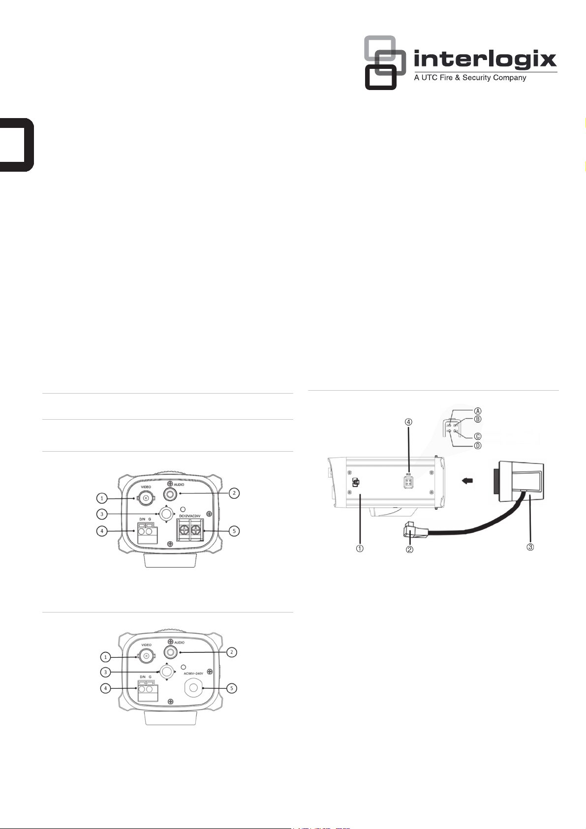
Figure 1: Camera UVC-6130-1-P/N description
1. Video output
2. Audio output
3. OSD control pad
Figure 2: Camera UVC-6130-1-P2 description
1. Video output
2. Audio output
3. OSD control pad
4. D/N trigger pin
5. 12 VDC / 24 VAC dual power
4. D/N trigger pin
5. AC96V/AC240 universal
power
1. Camera
2. Autoiris lens plug
3. Lens (autoiris shown)
Screw the lens clockwise onto the lens mount of the camera. For
optimal performance, please use an auto iris lens. Plug the autoiris drive cable to the 4-pin interface on the side of the camera.
Note: Please prevent dust from entering between the lens mount
and the lens.
3. Connect the power cable.
For UVC-6130-1-P/N:
With a screwdriver, loosen the ~AC24V/DC12V and GND terminal
screws on the terminal block. Connect a universal 12 VDC/24
VAC power supply to the terminal block.
Note: The terminal block is not polarity sensitive. Either power
lead can be connected to either terminal connector. There is no
need for an isolated ground wire. The two power terminals can
accept any polarity and any combination of power that equals 12
VDC or 24 VDC.
4. DC type autoiris lens leads
A. Damping coil (+); B.
Damping coil (-); C Driving
coil (+); D Driving coil (-)
© 2012 UTC Fire & Security. All rights reserved. 1 / 2 P/N 1072548C-EN • REV 1.0 • ISS 27JUL12
Page 2
Retighten the terminal screws until snug, ensuring that the power
leads are secure. Supply power to the unit by plugging the power
supply into a proper source.
Note: The power LED illuminates to show that the camera is
receiving power. If it does not illuminate, check the terminal block
connections and the power source
For UVC-6130-1-P2:
Connect the power cable of a high voltage camera to either a 230
VAC or a 120 VAC power supply outlet.
Programming
Once the camera hardware has been installed, the camera can then
be configured. Program the camera by attaching a standard video
monitor to the system.
OSD control pad
The on-screen display (OSD) control pad (see Figure 1/Figure 2) is a
five-direction button that lets you manually control the camera
functions. Table 1 below lists the OSD control pad functions and
describes their use.
Table 1 Description of the OSD control pad
Pad direction Description
Up Moves the cursor upward to select an item
Left Moves the cursor left to select or adjust the options
of the selected item.
Right Moves the cursor to the right to select or adjust the
options of the selected item.
Down Moves the cursor downward to select an item.
Enter Press the center of the control pad to display the
Setup menu. If the selected item has its own menu,
press the control pad to enter a submenu.
Accessing the menus
Press Enter on the camera’s OSD control pad to display the Setup
menu (see Figure 4 below). The Setup menu provides access to the
camera configuration options (Figure 5). The OSD is only available in
English.
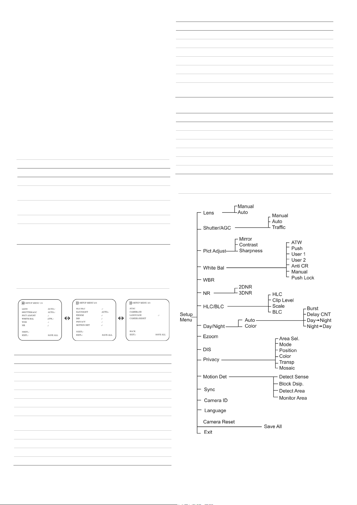
Menu item Description
Motion Det Defines the motion detection set up.
Sync Displays the current synchronization mode.
Camera ID Defines the camera ID displayed on-screen.
Language Defines the language of the OSD.
Camera Reset Resets the camera to factory default settings.
Save All Saves all configuration changes made.
Exit Exits the menu and returns to live mode. Saves
changes made.
Specifications
Model UVC-6130-1-N(P) UVC-6130-1-P2
Lens type C/CS-DC drive
Power supply 24 VAC / 12 VDC 96 to 240 VAC
Current 300 mA Max. 50 mA
Power consumption Max. 3.6 W Max. 4.8 W
Operating temperature -10 to +50 °C (14 to 122 °F)
Weight 390 g (0.85 lbs)
Menu map
Figure 5: Menu map
Figure 4: Setup menu screen
Table 2: Setup menu description
Menu item Description
Lens Defines the lens type as manual or autoiris.
Shutter/AGC Defines the method of light control.
Pict Adjust Defines the image quality functions.
White Bal Defines the white balance (WB) set up.
WDR Defines the wide dynamic range (WDR) set up.
NR Defines the digital noise reduction level.
BLC/HLC Defines the highlight compensation (HLC) and
backlight compensation (BLC) set up.
Day/Night Defines the day/night (D/N) set up.
EZoom Enables/disables digital zoom.
DIS Enables/disables the digital image stabilizer.
Privacy Defines privacy mask set up.
2 / 2 P/N 1072548C-EN • REV 1.0 • ISS 27JUL12
 Loading...