

Interlogix TX-C series Installation Instructions Manual
TX-CXXX Installation Instructions
Description
The Micro Door/Window Sensor is a
supervised, wireless sensor that detects the
opening and closing of doors or windows.
The sensor and magnet are mounted using
screws (included) or double-sided adhesive
tape (included)
When activated, the sensor transmits an
open (trip) or close (restore) signal to the
panel. These are the signals the unit
provides: supervisory, tamper and low
battery (as needed). The sensor is powered
by (2) replaceable 3-VDC, lithium coin-cell
batteries.
Installation Guidelines
• Mounting the sensor on metal can affect
the transmitting range and magnet gap
performance. Therefore, test the sensor
from the desired location using the installer
sensor test, before permanently mounting.
• Mount the sensor within 100 ft. of the
panel.
• Mount the sensor on the frame, and the
magnet on the door, window or drawer. If
mounting on double doors, mount the
sensor on the least used door and the
magnet on the other door.
• Mount sensors at least 5 inches above the
floor to avoid damaging them.
• The sensors can be mounted to either
wood or metallic surfaces.
• The magnet should be mounted within
5/16” (8 mm) for wood or ¼” (6 mm) for
metal installations. Based on the magnet
mounting spacing, direction of operation
and material of the mounting surface, the
gap for opening will vary between 1/8” (3
mm) and 1 ¾” (44 mm). Desired operation
should be checked before permanent
installation.
• After mounting the sensor, retest the
sensor using the procedure in the section
“Testing the Sensor”.
Programming
The following steps describe the general
guidelines for programming the sensor into
panel memory. Refer to the specific panel’s
documentation for complete programming
details.
1. Set the panel to the program mode.
2. Proceed to the SENSORS menu.
3. Select the appropriate sensor group and
sensor number assignments.
4. When prompted by the panel to trip the
sensor for learning, remove the sensor
cover and if present pull the battery pull
tabs. The system should acknowledge
learning the sensor by touchpad display
and/or audio (depending on the panel).
5. Exit program mode.
Testing the Sensor
1. Set the panel to the sensor test mode.
2. Take the sensor and magnet to the
desired mounting location, making sure to
line up their alignment marks with each
other. Trip the sensor by pulling the magnet
away from the sensor.
3. Monitor the system after tripping the
sensor. Refer to the specific panel
documentation for interpretation of the
results to ensure desired signal strength is
achieved.
I-TX-CXXXX Rev.1 Mar 2017

Model no.
RF-CMDWS - 319
RF frequency
319.5 MHz
Compatibility
Interlogix Learn Mode Panels
and Receivers – Concord,
NetworX and Simon Series
Battery type
(2) 3-VDC, lithium coin-cell
battery (Varta or Panasonic,
Model CR2032)
Battery
Varta CR2032
Panasonic CR2032
Operating
temperature
range
32 to 120°F (0 to 49°C)
Storage
temperature
range
-30 to 140°F (-34 to
60°C)
Relative
humidity
95% non-condensing
Dimensions
(L x W x D)
2.25 x 1.0 x 0.50 in.
TX-CXXX Installation Instructions
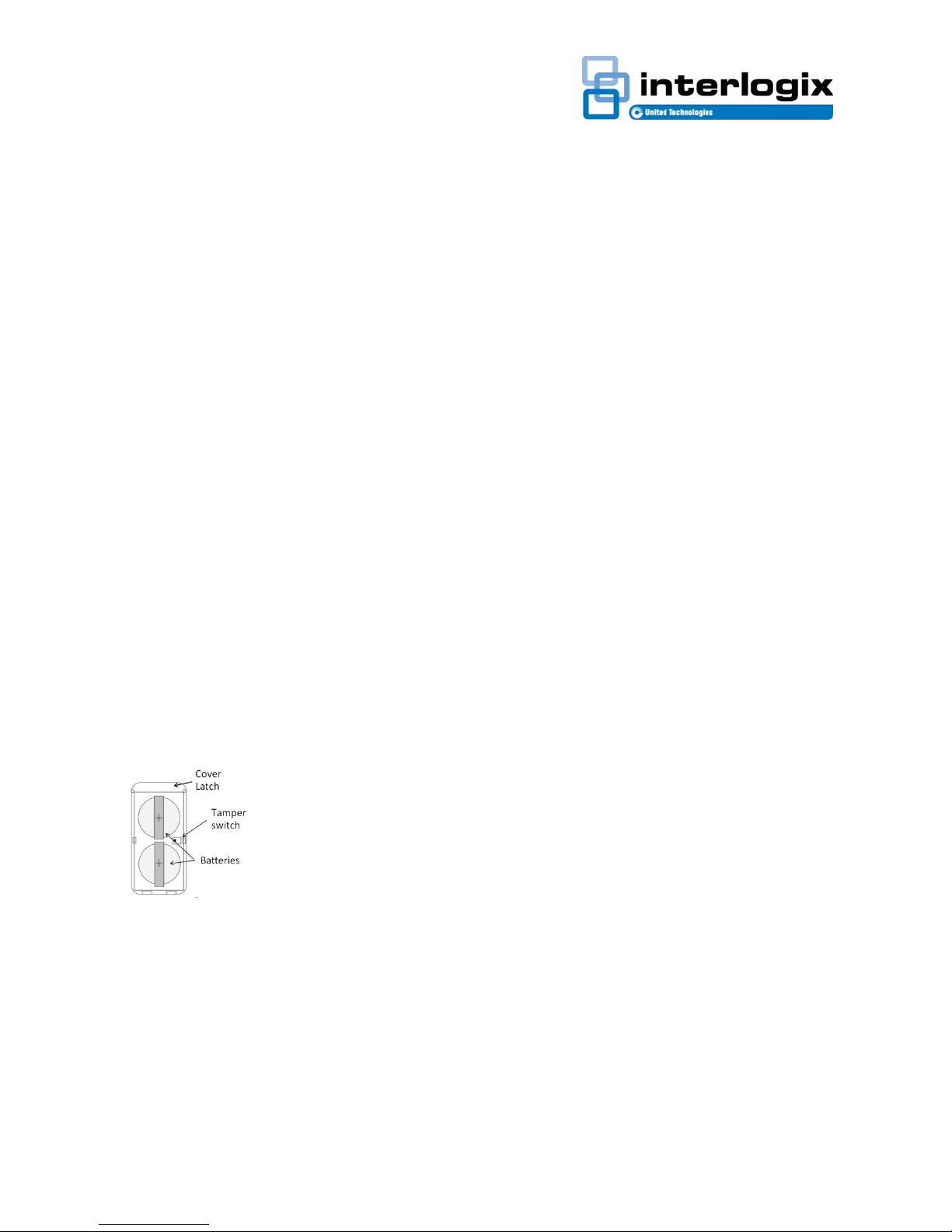
Note: If a low battery alarm occurs, replace
the battery within 7 days.
CAUTION: Battery may explode if
mistreated. Do not recharge, disassemble
or dispose of in fire.
Mounting the Sensor
Mount the sensor using the supplied mounting
screws for permanent mounting installations or
using the supplied double-sided tape is optional.
Note: The gap between the sensor and magnet
should not exceed a maximum of 3/8”.
Mounting Screws
1. Remove the sensor base from the sensor.
2. Place the sensor base in desired location and
mount the base with the supplied screws. Attach
the sensor to the base.
3. Mount the magnet into the desired location
using the supplied screw and lock washer,
making sure the alignment mark lines up with
the sensor mark.
Double-Sided Tape
1. Before applying double-sided tape, ensure
that the desired location is a smooth, clean and
dry surface.
Note: When applying the double-sided tape,
evenly apply pressure to ensure a good surface
contact.
2. Apply double-sided tape to the bottom of the
sensor and the magnet. Mount the sensor and
magnet at the desired locations, ensuring the
alignment marks line up with each other.
For Additional Tamper Security
1. Punch out the tamper cover on the bottom of
the sensor, and using the small screw secure it
to the mounting location, when the sensor is
removed “tampered” the tab remains providing a
tamper condition.
Specifications
I-TX-CXXXX Rev.1 Mar 2017
 Loading...