

Page 1

TruVision
Wedge
Dome Back Box an
Dual View Mount
Installation Guide
P/N 1073093A-EN • REV A • ISS 30SEP15
d
Page 2

Copyright
© 2015 United Technologies Corporation,
Interlogix is part of UTC Building & Industrial Systems, a unit of United
Technologies Corporation. All right s reserved.
Trademarks and patent s
Trade names used in this document m ay be trademarks or registered trademarks
of the manufacturers or vendors of the respectiv e products.
Contact information
For contact information, see www.interl ogix.com or
www.utcfssecurityproducts.eu.
Page 3

Content
Product overview 3
Product and package contents 4
TVW-DVM dual view mount 4
TVW-AW B-1 outdoor angled back box 6
TVW-AW B-2 indoor angled back box 8
TVW-2G-AD adapter plate 9
Installation 12
Specifications 23
TruVision wedge camera bracket and mount 23
Product overview
This is the installation guide for the following TruVision wedge
camera models:
TVW-DVM (dual view mount) (use with TVD-PPB)
TVW-AW B-1 (angled back box for outdoor appli cation)
TVW-AW B-2 (angled back box for indoor application)
TVW-2G-AD (Adapter plate for wedge camera with 2-gang
box)
Installation Guide 3
Page 4
Product and package contents
Check the package and contents for visible damage. If any
components are damaged or missing, do not attempt to use the
unit; contact the supplier immediately. If the unit is returned, it
must be shipped back in its original packaging.
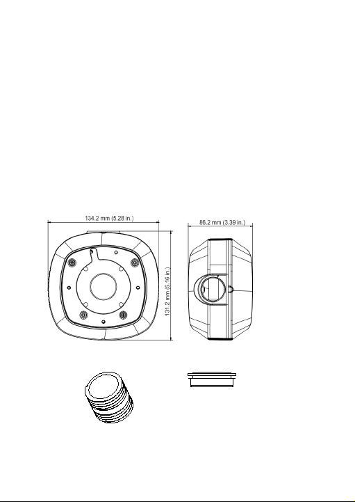
TVW-DVM dual view mount
The TVW -DVM dual view mount (purchased separately) allows
you to install two panoramic cameras on a single mount. You
then obtain a view of the surrounding area without requiring a
complex integration effort when connecting to your storage
device or video management system (VMS).
Camera mount:
Tube adapter (30 x 12 mm): Conduit cover/plug:
4 Installation Guide
Page 5
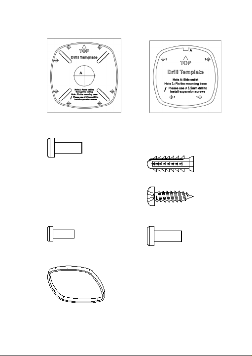
Template A:
Template B:
Screw 3 x 10 m (5 pcs m):
Screw (10 pcs):
Drywall anchor 7.5 x
24.5 mm
M4 screw 4 x 25 mm
Screw 3 x 8 mm (2 pcs):
Screw 4 x 10 mm (5 pcs):
Rubber ring:
Installation Guide 5
Page 6
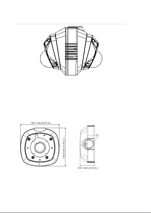
Figure 1: Cameras attached using the dual view mount
TVW-AWB-1 outdoor angled back box
The TVW -AWB-1 outdoor angled back box (purchased
separately) is weather resistant and includes a G1 threaded
conduit access and plug. It conceals the interconnect cables
and eliminates the blind area below the camera when the
camera is installed on a wall.
Camera back box:
6 Installation Guide
Page 7
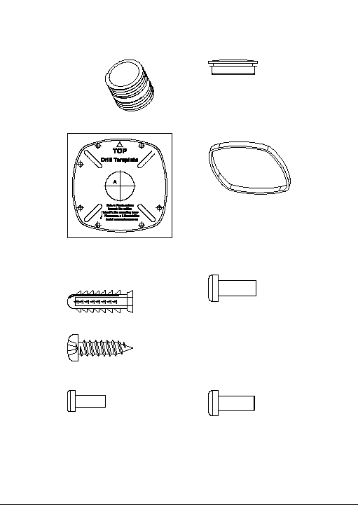
Tube adapter (30 x 12 mm):
Conduit cover/plug:
Template A:
Rubber ring:
Screw (5 pcs):
Screw 3 x 10 mm (5 pcs):
Drywall anchor 7.5 x 24.5 mm
M4 screw 4 x 25mm
Screw 3 x 8 mm (2 pcs):
Screw 4 x 10 mm (3 pcs):
Installation Guide 7
Page 8
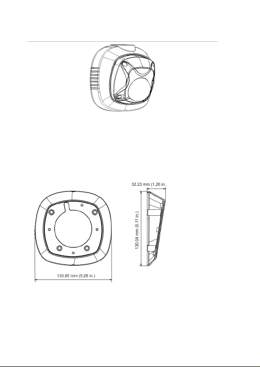
Figure 2: Camera mounted on an outdoor back box
TVW-AWB-2 indoor angled back box
The TVW -AWB-2 indoor angled back box (purchased
separately) conceals the interconnected cables and eliminates
the blind area below the camera when the camera is installed
on a wall.
Camera back box:
8 Installation Guide
Page 9
Template B:
Screw 5 pcs:
Drywall anchor (7.5 x
24.5 mm)
M4 screw (4 x 25 mm)
Screw 3 pcs (4 x 10 mm):
Figure 3: Camera mounted on an indoor back box
TVW-2G-AD adapter plate
The TVW -2G-AD adapter plate (purchased separately) allows
you to attach the panoramic wedge camera to a standard 4-inch
2 gang box.
Installation Guide 9
Page 10

Camera adapter plate:
Template A:
Rubber ring:
10 Installation Guide
Page 11

Screw 5 pcs:
Screw 3 x 8 mm (2 pcs):
Drywall anchor (7.5 x 24.5 mm)
M4 screw (4 x 25 mm)
Screw 4 x 10 mm (3 pcs):
Figure 4: Wedge camera attached to a 2 gang box
Installation Guide 11
Page 12

Installation
To mount two wedge cameras on a dual view mount:
1. Attach the TVW-DVM dual view mount to an installed
pendant mount tube. An adapter is included in the kit that,
if required, can be used to match-up with the threading
(G1 male or G1 female) of the pendant mount tube.
2. Loosen the screws with the tamper-resistant hex wrench
(supplied) to remove the camera cover.
12 Installation Guide
Page 13

3. Pull the cables through the bracket tube and to both back
boxes, conect the cables to cameras and place the
connecters and cables into the back boxes.
4. Mount the two cameras on both sides of the TVW -DVM
dual view mount.
Installation Guide 13
Page 14

5. Re-attach the camera covers to the cameras.
To mount the wedge camera on an outdoor angled
back box:
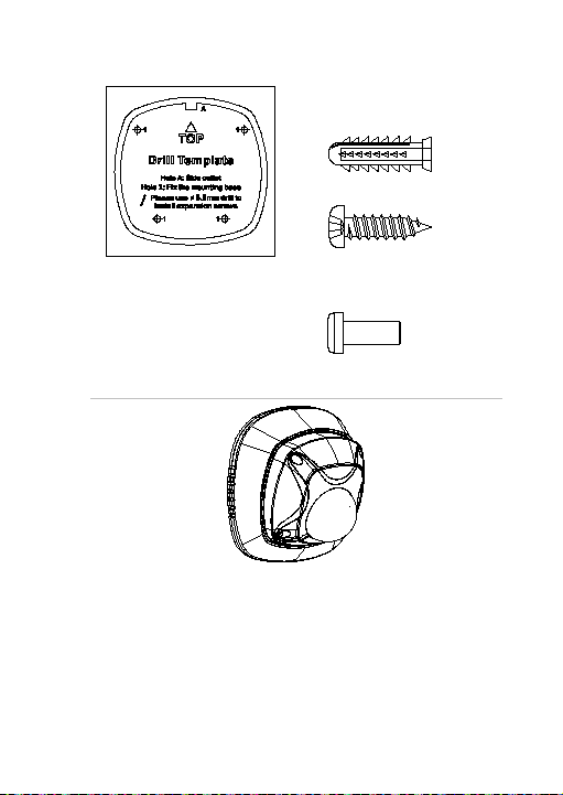
1. Drill the holes for the mounting hardware in the mo unting
surface using the supplied drill template.
14 Installation Guide
Page 15

2. Detach the TVW-2G-AD adaptor plate from the back box.
3. Mount the TVW-2G-AD adaptor plate to the mounting
surface using the supplied hardware.
4. Mount the outdoor angled back box to the TVW-2G-AD
adaptor plate using the supplied hardware.
Installation Guide 15
Page 16

5. Loosen the screws with the tamper-resistant hex wrench
(supplied) to remove the camera cover.
6. Connect the cables, conceal the cables and connectors
inside the back box and mount the camera base to the
outdoor angled back box.
16 Installation Guide
Page 17

7. Re-attach the dome cover to the camera.
To mount the wedge camera on an indoor angled back
box:
1. Drill the holes for the mounting hardware in the mo unting
surface using the supplied drill template.
Installation Guide 17
Page 18

2. Mount the indoor back box to the mounting surface by
using the supplied hardware.
3. Loosen the screws with the tamper-resistant hex wrench
(supplied) to remove the camera cover.
18 Installation Guide
Page 19

4. Connect the cables, conceal the cables and connectors
inside the back box, and m ount the camera base to the
indoor angled back box.
5. Re-attach the dome cover to the camera.
Installation Guide 19
Page 20

To mount the wedge camera on a 2-gang box:
1. Install the 2-gang box (separately purchased) in the wall
according to the local applicable codes and regulations
2. Attach the TVW-2G-AD adapter to a pre-installed 2-gang
box on wall.
20 Installation Guide
Page 21

3. Attach the enclosed rubber ring to the 2-gang box adapter.
4. Loosen the screws with the tamper-resistant hex wrench
(supplied) to remove the camera cover.
Installation Guide 21
Page 22

5. Connect the cables, conceal the cables and connectors
inside the 2-gang box and mo unt the camera base to the
2-gang box adapter.
6. Re-attach the camera cover to the camera.
22 Installation Guide
Page 23

Specifications
TVW
Dimensions (L × W × H)
Weight
T
Dimensions (L × W × H)
Weight
TruVision wedge camera bracket and
mount
-DVM
VW-AWB-1
Installation Guide 23
134.2 × 131.2 × 86.2 mm
(5.28 × 5.16 × 3.9 in.)
422 g (0.93 lb.)
134.1 × 130.9 × 54 mm
(5.27 × 5.15 × 2.12 in.)
321 g (0.71 lb.)
Page 24

T
VW-AWB-2
Dimensions (L × W × H)
Weight
TVW
Dimensions (L × W × H)
Weight
133.9 × 130 × 32.2 mm
(5.27 × 5.12 × 1.26 in.)
101 g (0.22 lb.)
-2G-AD
134.1 × 130 × 13.5 mm
(5.27 × 5.12 × 0.53 in.)
129 g (0.28 lb.)
24 Installation Guide
Page 25

Page 26

Page 27

Page 28

 Loading...