

Page 1

TruVision
Analog Wedge Camera
Installation Guide
TVW
P/N 1073422-EN • REV A • ISS 14MAY18
HD-TVI (1080P) /
-6101
Page 2

Page 3

Content
Product overview 2
Contact information and
manuals/tools/firmware 2
Package contents 3
Camera description 6
Installation 7
Program 14
Using a TVI output 15
Call up the camera OSD (On Screen
Display) menu 15
Menu tree 18
Video format (NTSC/PAL) 19
Specifications 19
Legal and Regulatory information 20
Installation Guide 1
Page 4

Product overview
EMEA:
www.firesecurityproducts.com
This is the Installation Guide for the HD-TVI
(1080P) / analog wedge camera TVW -6101. This
guide describes a standard installation.
The configuration manual is available from our web
site.
Contact information and manuals/tools/firmware
For contact information and to download the latest
manuals, tools, and firmware, go to the web site of
your region.
Americas: www.interlogix.com
Manuals are available in
several languages.
Australia/Ne w
Zealand:
2 Installation Guide
www.utcfs.com.au
Page 5
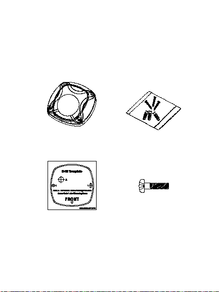
Package contents
Camera
assembly (cable
harness not
shown)
Camera drill
template
3 M4 x 25 mm
screws and 3
anchors for wall
or ceiling
installation
2 screws M4 x 8
used for installing
the camera to the
adapter plate
Installation Guide 3
Page 6
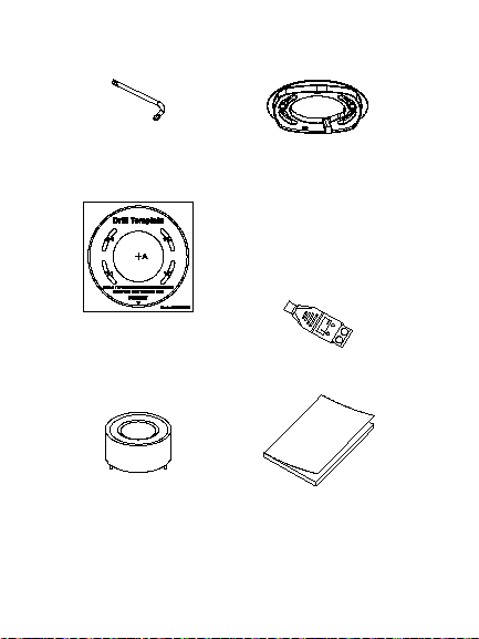
Torx wrench
Adapter plate
Adapter plate drill
template
12 VDC
connector (2
terminal
connectors with
positive and
negative
indicators)
Lens adjustment
tool
4 Installation Guide
Installation guide
Page 7

• Equipment
disposal sheet
Installation Guide 5
Page 8
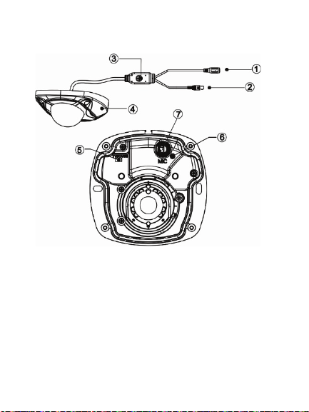
Camera description
4. Camera housing
1. 12 VDC power cable
2. TVI / 960H analog
video output
3. OSD menu button
6 Installation Guide
5. TVI / 960H analog
switch
6. Power LED
7. MIC (Audio not
supported)
Page 9

Note: When using the HD-TVI output, the HD-TVI
wedge camera should only be connected to a DVR
that supports a TVI signal.
Installation
To install the camera on a surface:
1. Use the camera drill template to mark the
mounting holes.
2. Follow all local safety regulations. Drill through
the mounting surface. If you need to route the
cables from the bottom of the camera, drill a
larger hole in the mounting surface for the
cable harness.
3. Using the Torx wrench, loosen the four screws
to remove the housi ng cover from the device.
Installation Guide 7
Page 10

4. Install the mounting base to the surface using
two of the M4 x 25 mm screws and anchors. If
routing the cable harness through the ceiling,
do so prior to mounting the camera.
5. Loosen the Philips screw, located near the lens
assembly. Align the lens adjustment tool with
the two small holes located on the camera
assembly.
Rotate (pan) the camera assembly using the
lens adjustment tool until the lens is positioned
8 Installation Guide
Page 11

in the correct location. The tool is also used to
Philips screw
Pan
Lens adjustment tool
Tilt
Rotation
adjust the tilt angle.
Installation Guide 9
Page 12

Note: Please do not remove the foam ring
attached to the lens. This foam ring is required
to reduce the glare of IR illuminators.
6. Tighten the Torx screw and re-install the
housing cover to the camera assembly using
the Torx wrench.
To install the camera using the adapter plate:
1. Use the adapter plate drill template to mark the
holes.
10 Installation Guide
Page 13

2. Follow all local safety regulations. Drill through
the mounting surface. If you need to route the
cables from the bottom of the camera, drill a
larger hole for the cable harness.
3. Install the adapter plate to the using two of the
M4 x 25 mm screws and anchors.
Installation Guide 11
Page 14

4. Using the Torx wrench, loosen the four screws
to remove the housi ng cover from the device.
5. Install the camera base to the adapter plate
using the two M4 x 8mm screws.
6. Loosen the Philips screw located near the lens
assembly. Align the lens adjustment tool with
the two small holes located on the camera
assembly.
12 Installation Guide
Page 15

Rotate (pan) the camera assembly using the
Philips screw
Pan
Lens adjustment tool Tilt
Rotation
lens adjustment tool until the lens is positioned
in the correct location. The tool is also used to
adjust the tilt angle.
Installation Guide 13
Page 16

Note: Please do not remove the foam ring
attached to the lens. This foam ring is required
to reduce the glare of IR illuminators.
7. Tighten the Philips screw and re-install the
housing cover to the camera assembly using
the Torx wrench.
Program
In HD-TVI or Analog mode, use the OSD (On
Screen Display) button to program the camera. The
button is located on the cable harness. In HD-TVI
mode, the OSD menu can also be accessed via the
TVI recorder.
14 Installation Guide
Page 17

Using a TVI output
Once the camera has been installed, you can
configure the camera settings on the TVI DVR.
Connect the TVI cable to the DVR, as shown.
Select the PTZ protocol TruVision Coax and click
the Menu button to call up the camera menu.
For more details, refer to the TVI DVR user manual.
Call up the camera OSD (On Screen Display) menu
To set up the camera in HD-TVI mode:
1. In Camera Settings of the DVR, access the
PTZ menu and select the TruVision -Coax
protocol for the TruVision HD-TVI camera from
the drop down menu.
Installation Guide 15
Page 18

2. In live view of the desired camera, click the
PTZ Control icon on the live view toolbar to
access the PTZ control panel.
3. To call up the camera setup menu:
From the camera OSD of the DVR, select
Menu.
— or —
From the DVR, select Iris+.
The camera setup menu appears (see “Menu
tree” on page 18 for the menu structure).
4. Select the menu options:
From the TVI recorder (HD-TVI mode): To
select an OSD item, click the directional
buttons up/down. To adjust the value of a
selected item, click the directional buttons
left/right.
From the camera (HD-TVI or Analog mode):
The OSD button is located on the cable
harness. To select an OSD item, push the
Menu button up/down. To adjust the value of a
selected item, push the Menu button left/right.
16 Installation Guide
Page 19

5. Click Iris+ to enter the submenu or to confirm
the selected item.
6. When the setup is complete, select Exit and
click Iris+ to exit the camera OSD.
Note: You cannot exit the camera setup menu
using the Menu button on the camera.
Installation Guide 17
Page 20

Menu tree
18 Installation Guide
Page 21

Video format (NTSC/PAL)
Power supply
12 VDC
Current
Power
consumption
3.5 W max.
Operating
temperature range
Weight (net)
260 g (0.57 lb.)
Dimensions
Under Format, select PAL or NTSC.
Specifications
Installation Guide 19
290 mA max.
-40 to +60 °C (-40 to +140 °F)
99.5 x 97 x 46.8 mm
(3.92 x 3.82 x 1.84 in. )
Page 22

Legal and Regulatory
information
Class A: This equipment has been tested and found to comply with
erated in a commercial environment. This equipment generates,
and used in accordance with the instruction manual, may cause
Copyright:
© 2018 United Technologies Corporation,
Interlogix is part of UTC Climate, Controls & Security, a unit of
United Technologies Corporation. All rights reserved.
Trademarks and patents:
Trade names used in this document may be trademarks or
registered trademarks of the manufacturers or vendors of the
respective products.
Manufacturer:
Interlogix
2955 Red Hill Avenue, Costa Mesa, CA 92626-5923, USA
Authorized EU manufacturing representative:
UTC Fire & Security B.V.
Kelvinstraat 7, 6003 DH Weert, The Netherlands
Certifica tion:
FCC compliance: Class A
the limits for a Class A digital device, pursuant to part 15 of the
FCC Rules. These limits are designed to provide reasonable
protection against harmful interference when the equipment is
op
uses, and can radiate radio frequency energy and, if not installed
20 Installation Guide
Page 23

harmful interference to radio communications. Operation of this
equipment in a residential area is likely to cause harmful
2012/19/EU (WEEE directive): Products
marked with this symbol cannot be disposed of
interference in which case the user will be required to correct the
interference at his own expense.
ACMA compliance
Notice! This is a Class A product. In a domestic environment this
product may cause radio interference in which case the user may
be required to take adequate measures.
Canada
This Class A digital apparatus complies with Canadian ICES-003.
Cet appareil numérique de la classe A est conforme à la norme
NMB-0330 du Canada.
European Union directives:
12004/108/CE (EMC directive): Hereby, UTC Fire & Security
declares that this device is in compliance with the essential
requirements and other relevant provisions of Directive
2004/108/EC.
as unsorted municipal waste in the European
Union. For proper recycling, return this product
to your local supplier upon the purchase of
equivalent new equipment, or dispose of it at
designated collection points. For more
information see: www.recyclethis.info.
Product warnings and disclaimers:
THESE PRODUCTS ARE INTENDED FOR SALE TO AND
INSTALLATION BY QUALIFIED PROFESSIONALS. UTC FIRE &
SECURITY CANNOT PROVIDE ANY ASSURANCE THAT ANY
PERSON OR ENTITY BUYING ITS PRODUCTS, INCLUDING
ANY “AUTHORIZED DEALER” OR “AUTHORIZED RESELLE R”,
IS PROPERLY TRAINED OR EXPERIENCED TO CORRECTL Y
INSTALL FIRE AND SECURITY RELATED PRODUCTS.
Installation Guide 21
Page 24

For more information on warranty disclaimers and product safety
information, please check
Contact information and manuals / tools / firmware
For contact information and to download the latest manuals, tools,
and firmware, go to the web site of your
Americas: www.interlogix.com
EMEA: www.firesecurityproducts.com
Manuals are available in several languages
Australia/New Zealand: www.utcfs.com.au
www.firesecurityproducts.com/policy/product-warning/ or scan the
following code:
:
region.
22 Installation Guide
 Loading...