

Page 1

TruVision
Panoramic
Wi
Camera Installation
Guide
P/N 1073033-EN • REV A • ISS 29SEP15
-Fi Wedge IP
Page 2

Copyright
expressly approved by the part y responsible for compliance could void the user’s
© 2015 United Technologies Corporation,
Interlogix is part of UTC Building & Industrial Systems, a unit of United
Technologies Corporation. All right s reserved.
Trademarks and patent s
Trade names used in this document m ay be trademarks or registered trademarks
of the manufacturers or vendors of the respectiv e products.
Manufacturer
Interogix
2955 Red Hill Avenue, Costa Mesa, CA 92626-5923, USA
UTC Fire and Security Inc.
858 Partridge Dr., Burlingt on, ON
Authorized EU manufacturing representat ive:
UTC Fire & Security B.V.
Kelvinstraat 7, 6003 DH Weert, The Net herlands
Certification
N4131
This equipment has been tested and f ound to comply with the limits for a Class B
digital device, pursuant to P art 15 of FCC Rules. These limits are designed t o
provide reasonable protecti on against harmful interference in a resident ial
installation. This equipment generates, uses, and can radiate radio frequency
energy and, if not installed and used in accordance with the instructi ons, may
cause harmful interference to r adio communications. However, there is no
guarantee that interference will not occur in a particular installation. If this
equipment does cause harmful i nterference to radio or television recepti on, which
can be determined by turning the equipment off and on, the user is encouraged
to try to correct the interf erence by one or more of the following measures:
1. Reorient or relocate the receiving antenna.
2. Increase the separation bet ween the equipment and receiver.
3. Connect the equipment i nto an outlet on a circuit different f rom that to which
the receiver is connected.
4. Consult the dealer or an experienced r adio technician for help.
CC Caution
To assure continued complianc e, use only shielded interface cables when
connecting to computer or peri pheral devices. Any changes or modificati ons not
Page 3

authority to operate the equipm ent.
This device complies with Part 15 of the FCC Rules. Operation is subject to the
following two conditions:
(1) This device may not cause harmful interference
(2) This Device must accept any interference received, including interference that
may cause undesired operation.
Any changes or modifications not ex pressly approved by the party responsible f or
compliance could void the user’s authori ty to operate the equipment.
Federal Communication Commission (FCC) Radiation Expo sure Statement
This equipment c omplies with FCC radiation exposure set f orth for an
uncontrolled environment. I n order to avoid the possibility of exc eeding the FCC
radio frequency exposure limit s, human proximity to the antenna shall not be less
than 20 cm (8 inches) during normal operation.
CAN ICES-3 (B)/NMB-3(B)
This device complies with Industr y Canada licence-exempt RSS standard(s).
Operation is subject to the foll owing two conditions:
(1) this device may not cause int erference, and
(2) this device must accept any int erference, including interference that may
cause undesired operation of the device.
Le présent appareil est conform e aux CNR d'Industrie Canada applicables aux
appareils radioexempts de licence. L'ex ploitation est autorisée aux deux
conditions suivantes :
(1) l'appareil ne doit pas produir e de brouillage, et
(2) l'utilisateur de l'appar eil doit accepter tout brouillage radi oélectrique subi,
même si le brouillage est susceptibl e d'en compromettre le fonctionnement.
Under Industry Canada regulati ons, this radio transmitter may only oper ate using
an antenna of a type and maximum (or l esser) gain approved for the transmitter
by Industry Canada. To reduce pot ential radio interference to other users, the
antenna type and its gain should be so chosen that the equivalent isotropi cally
radiated power (e.i.r.p.) i s not more than that necessary for successful
communication.
Conformément à la réglementation d'Industr ie Canada, le présent émetteur radio
peut
fonctionner avec une antenne d'un t ype et d'un gain maximal (ou inférieur)
approuvé pour l'émetteur par I ndustrie Canada. Dans le but de réduire l es
risques de brouillage radi oélectrique à l'intention des autres util isateurs, il faut
choisir le type d'antenne et son gai n de sorte que la puissance isotrope rayonnée
équivalente (p.i.r.e.) ne dépasse pas l'intensité nécessaire à l' établissement d'une
communication satisfaisante.
Page 4

R&TTE Compliance Statement
Bulgaria
None
General authorization requir ed for
France
Outdoor use;
Military Radiolocation use. Refarming
Luxembourg
None
General authorization requir ed for
Norway
Implemented
This subsection does not apply for the
Italy
Implemented
The public use is subject to general
Russian
Limited
1. SRD with FHSS modulation
This equipment complies with all t he requirements of DIRECTIVE 1999/5/CE OF
THE EUROPEAN PARLIAMENT AND THE COUNCIL OF 9 March 1999 on radio
equipment and telecommunication termi nal Equipment and the mutual
recognition of their conformi ty (R&TTE). The R&TTE Directive repeals and
replaces in the directive 98/13/EEC (Telec ommunications Terminal Equipment
and Satellite Earth Station Equi pment) as of April 8, 2000.
Safety
This equipment is designed with t he utmost care for the safety of those who
install and use it. However, special attention must be paid to the dangers of
electric shock and static elect ricity when working with electrical equi pment. All
guidelines of this and of the c omputer manufacture must therefore be allowed at
all times to ensure the safe use of the equipment.
National Restrictions
This device is intended for home and office use in all EU countri es (and other
countries following the EU di rective 1999/5/EC) without any limitation ex cept for
the countries mentioned below:
Country Restriction Reasons/remarks
outdoor use and public service
limited to 10 mW
e.i.r.p. within the
band 2454-
2483.5 MHz.
Annex 3 B and A Wideband Data Transmi ssion systems 2400.0-2483.5 MHz:
Country Restriction Reasons/remarks
Federation
implem entation
of the 2.4 GHz band has been ongoing
in recent years to allow current relaxed
regulation. Full im plementation
planned 2012
network and service supply(not f or
spectrum).
geographical area within a radi us of
20 km from the centre of Ny-Ålesund.
authorization by the respectiv e service
provider.
1.1. Maximum 2.5 mW e.i.r.p.
Page 5

1.2. Maximum 100 mW e.i.r.p.
Permitted for use SRD for outdoor
Ukraine
Limited
e.i.r.p. ≤100 mW wit h built-in antenna
The following information shal l also be included in the case of radio equipm ent
2012/19/EU (WEEE directive): Products marked with this
applications without restri ction on
installation height only for purposes of
gathering telemetry informati on for
automated monitoring and resources
accounting systems. Permitted to use
SRD for other purposes for outdoor
applications only when the i nstallation
height is not exceeding 10 m ab ove
the ground surface. 1.3 maximum
100 mW e.i.r.p. indoor applications.
2. SRD with DSSS and other than
FHSS wideband modulation
2.1. Maximum mean e.i.r.p. density is
2 mW/MHz. Maximum 100 mW e.i.r.p.
2.2. Maximum mean e.i.r.p. density is
20 mW/MHz. Maximum 100 mW
e.i.r.p. It is permitted t o use SRD for
outdoor applications only for purposes
of gathering telemetry inf ormation for
automated monitoring and resources
accounting systems or securit y
system s.
2.3. Maximum mean e.i.r.p. density is
implem entation
10 mW/MHz. Maximum 100 mW
e.i.r.p. indoor applications.
with am plification factor up to 6 dBi.
intentionally emitting radi o waves:
(a) frequency band(s) in which t he radio equipment operates;
(b) maximum radio-frequency power transmitted in the frequency band(s) i n
which the radio equipment operat es.
symbol cannot be disposed of as unsorted m unicipal waste
in the European Union. For proper recycling, return this
product to your local supplier upon the purchase of
equivalent new equipment, or dispose of it at designated
collection points. For more informati on see:
www.recyclethis.info.
Page 6

2006/66/EC (battery directive): Thi s product contains a
battery that cannot be disposed of as unsorted municipal
For contact informati on, see www.interlogix.com or
waste in the European Union. See t he product
documentation for specific battery information. The battery
is marked with this symbol, which may include lettering to
indicate cadmium (Cd), lead (Pb) , or mercury (Hg). For
proper recycling, return t he battery to your supplier or to a
designated collection point. For more inf ormation see:
www.recyclethis.info.
Contact
www.utcfssecurityproducts.eu.
information
Page 7

Content
Introduction 2
Product overview 2
Installation 2
Installation environment 2
Package contents 3
Cable requirements 5
Camera description 6
Setting up the camera 6
Setting up Wi-Fi transmission 7
Accessing the SD card 14
Connecting a speaker 15
Alarm input connection 16
Alarm output connection 16
Resolution and viewing angle 18
Mounting the accessories 20
Mounting the wedge camera 23
Using the camera with a recorder 39
Using the camera with TruVision Navigator 39
Specifications 40
TruVision IP wedge cameras 40
Pin definitions 42
Installation Guide 1
Page 8

Introduction
Product overview
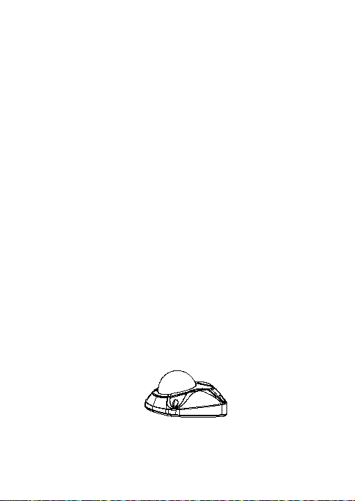
This is the installation guide for TruVision Panoramic wedge
camera models:
TVW-1130 (3MP X Panoramic, 1.6 mm lens, Gray, Wi-Fi,
PAL)
TVW-3130 (3MP X Panoramic, 1.6 mm lens, Gray, Wi-Fi,
NTSC)
Note:
The camera has a horizontal viewing angle range of between
127 to 160 degrees, depending on the resolution ratio settings.
Installation
This section provides information on how to install the cameras.
Installation environment
When installing your product, consider these factors:
• Electrical: Install electrical wiring carefully. It should be
done by qualified service personnel. Always use a proper
PoE switch or a 12 VDC UL listed Class 2 or CE certified
power supply to power the camera. Do not overload the
power cord or adapter.
• Ventilation: Ensure that the location planned for the
installation of the camera is well ventilated.
• Temperature: Do not operate the camera beyond the
specified temperature, humidity or power source ratings.
2 Installation Guide
Page 9
The operating temperature of the camera is between -30
to +60°C (-22 to 140°F). Humidity is below 90%.
• Moisture: Do not expose the camera to rain or moisture,
or try to operate it in wet areas. Turn the power off
immediately if the camera is wet and ask a qualified
service person for servicing. Moisture can damage the
camera and also create the danger of electric shock.
• Servicing: Do not attempt to service this camera yourself.
Any attempt to dismantle or remove the covers from this
product will invalidate the warranty and may also result in
serious injury. Refer all servicing to qualified service
personnel.
• Cleaning: Do not touch the sensor modules with fingers. If
cleaning is necessary, use a clean cloth with some ethanol
and wipe the camera gentl y. If the camera will not be used
for an extended period of time, put on the lens cap to
protect the sensors from dirt.
Package contents
Check the package and contents for visible damage. If any
components are damaged or missing, do not attempt to use the
unit; contact the supplier immediately. If the unit is returned, it
must be shipped back in its original packaging.
IP wedge camera
Camera:
Installation Guide 3
Page 10
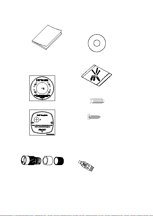
Installation manual:
CD with Configuration
Manual and TruVision Device
manager:
Template to mount with
Screws:
the converter pan:
Template A:
Drywall anchor
Φ7.5 x 24.5mm (3 pcs)
Template B:
Water j oint: provides
water resistance to
network connection.
Screw M4
(4 x 25mm (3 pcs)
12 VDC connector: DC jack
socket to terminal connectors
with positive and negative
indicators.
4 Installation Guide
Page 11
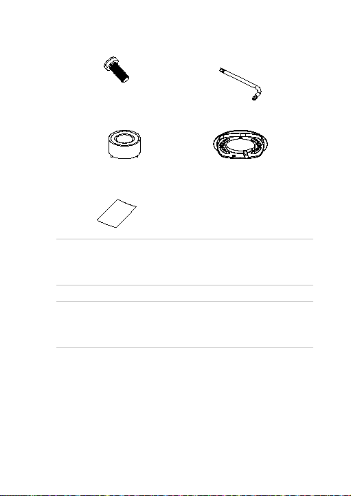
Screws C: M4×8, 2pcs
Lens alignment tool:
Tamper-resistant hex
wrench:
Converter pan:
WEEE and battery
disposal instructions:
CAUTION: Use direct plug-in UL listed power supplies marked
Class 2/CE certified or LPS (limited power source) of the
required output rating as listed on the unit.
CAUTION: Risk of explosion if battery is replaced by an
incorrect type. Dispose of used batteries according to the
instructions.
Cable requirements
For proper operation, adhere to the following cable and power
requirements for the cameras. Category 5 cabling or better is
recommended. All network cabling must be installed according
to applicable codes and regulations.
Installation Guide 5
Page 12
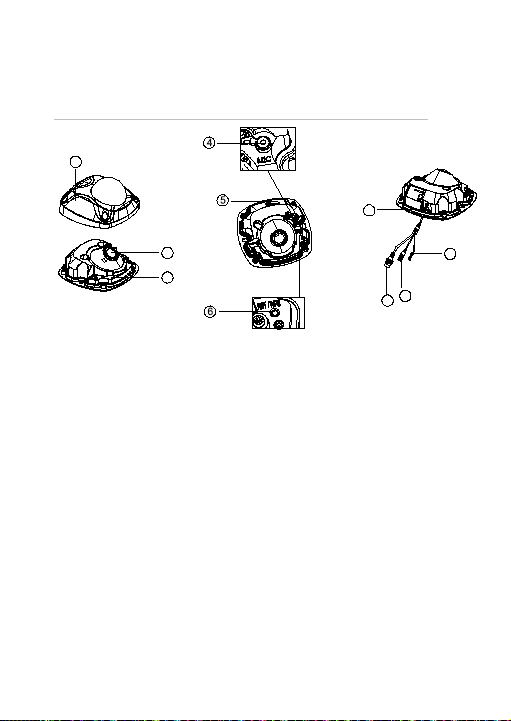
Camera description
5. Wi-Fi antenna
10. Alarm I/O and audio out
2
3
1
7
10
8
9
Figure 1: IP wedge camera
1. Cover
2. Lens
3. Base
4. Microphone
6. Reset button/WPS
7. SD card slot
8. PoE and network cable
9. DC power cable
Setting up the camera
Note: If the light source where the camera is installed
experiences rapid, wide variations in lighting, the camera may
not operate as intended.
6 Installation Guide
Page 13

To quickly put the camera into operation:
1. Prepare the mounting surface.
2 Mount the camera using the appropriate fasteners. See
“Mounting the wedge camera” on page 23.
3. Set up the camera’s network and streaming parameters so
that the camera can be controlled over the network.
4. Program the camera to suit its location. For further
information, please refer to the “TruVision Panoramic Wi-Fi
Wedge IP Camera Configuration Manual”.
Setting up Wi-Fi transmission
For setting up the Wi-Fi transmission, please refer to the
“TruVision Panoramic Wi-Fi Wedge IP Camera Configuration
Manual” for details.
Wi-Fi transmission distance
The Wi-Fi transmission distance/range of the camera is
approximately 50 m (164 ft.) in open air applications.
Note: The transmission distance may vary due to the presence
of physical obstacles, such as trees, walls, elevators, fire doors,
furniture, etc. Avoid very solid walls and metallic objects in the
transmission path. Other Wi-Fi networks (for example Wi-Fi,
WiMAX) operating on 2.4 GHz and certain types of devices
(e.g., microwave oven, point-to-point Wi-Fi transmission) can
cause interference with your network. The result would lead to a
reduction in transmission distance/range.
Installation Guide 7
Page 14
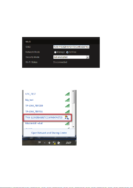
Access the camera via a Wi-Fi network (Ad-Hoc
mode)
Note: The camera is i n Ad-Hoc mode by default. The SSID is
the serial number.
1. Power up the camera.
2. From your computer, search for the SSID that was set up
for the camera for Ad-Hoc mode. Select the SSID to
connect the camera.
3. When connected, open TruVision Dev ice Finder or Device
Manager and change the IP address of the camera to that
of the same subnet of the router.
8 Installation Guide
Page 15
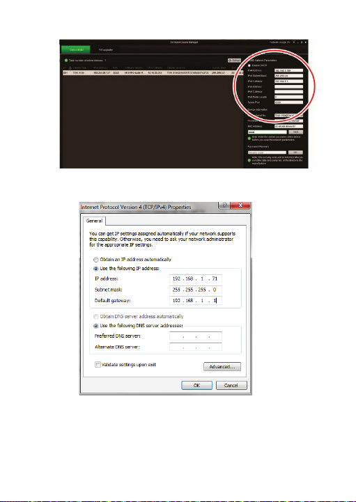
Note: The computer IP address should also be in the
same subnet.
4. Log on the camera via the web browser and browse to the
Wi-Fi page.
Installation Guide 9
Page 16
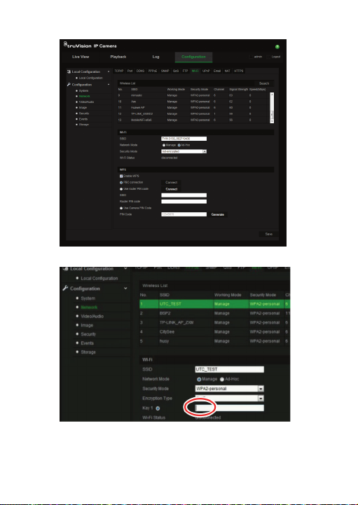
5. Select the desired Wi-Fi and enter the key, if required.
6. Click Save to save the settings.
10 Installation Guide
Page 17

7. When the camera is connected to the router, the ad-hoc is
disconnected. On your computer, select the Wi-Fi router
and connect it.
8. Open the device finder to check the WLAN IP address of
the camera.
Log in to the camera to see live view.
Installation Guide 11
Page 18

Access the camera via a network cable
When configuring the Wi-Fi settings, connect the camera to the
router via a network cable and then open the web browser t o
complete the Wi-Fi setup by clicking Save. W hen the Wi-Fi
Status changes from “Disconnected” to “Connected”, the Wi-Fi
connection is set up successfully. See Figure 2 below.
12 Installation Guide
Page 19

Figure 2: Camera browser Wi-Fi interface
WPS
The camera provides a WPS (Wi-Fi Protected Setup) feature to
easily set up a Wi-Fi connection to a Wi-Fi router.
Installation Guide 13
Page 20

Figure 3: WPS options
PBC mode: Push the WPS button on the Wi-Fi router. The
WPS indicator will flash. (The WPS settings may be different
per device. Please refer to the Wi-Fi router user manual for
details). Then check the PBC Connection checkbox and click
the Connect button. The camera and the Wi-Fi router are
automatically connected.
PIN mode: The PIN code is printed on the Wi-Fi router device.
Enter the PIN code in the Router PIN Code bar and check the
Use Router PIN Code. Then click Connect to connect the
camera to the Wi-Fi router.
You can generate the PIN code on the camera side and
configure the Wi-Fi router to finish the connection setting.
(Please check the Wi-Fi router User Manual for details). Please
note that the PIN code expiration time is 120 seconds.
Accessing the SD card
Insert a Micro SD card with up to 64GB for local storage as a
backup in case, for example, the network fails (see Figure 1 on
page 6). The SD card is not supplied with the camera.
14 Installation Guide
Page 21

Video and log files stored on the Micro SD card can only be
Audio Output
GND
accessed via the web browser. You cannot access the card
using TruVision Navigator or a recording device.
Connecting a speaker
The camera has a built-in microphone to collect audio signals
from the surveillance area. The audio signals can be configured
and transferred with video streams for live viewing and
recording purposes.
For audio output, please connect an external speaker to the
Audio Output and GND interface of the camera. The speaker is
not supplied with the camera. See Figure 4 bel ow.
Figure 4: Connecting a speaker to the camera
Note: The speaker must be correctly powered using a power
supply. Please check the speaker specification and user
manual for further details.
Installation Guide 15
Page 22

Using Audio for surveillance purpose and/or recording must
Camera
comply with local applicable codes and regulations.
Alarm input connection
The camera supports the external alarm input as shown below.
Both NO (Normally Open) and NC (Normally Closed) type
relays are supported. Please remember to check the Alarm
menu by selecting the NO/NC alarm type according to the
connected electric relay type.
Alarm input
GND
Alarm output connection
The camera can trigger an external alarm device when a motion
detection event occurs.
Please note that the camera GND must be always connected to
the negative power terminal. The maximum current into the
camera “Alarm Output” is 30 mA at 12 VDC.
16 Installation Guide
Page 23

Alarm output connection for a DC load:
Camera
1. Alarm output
2. GND
Camera
1. Alarm output
2. Alarm
3. GND
Camera
1. Alarm output
2. GND
3. Electric relay
Alarm output connection for an AC load:
Note: In this connection, the resistance load to the camera is
greater than 4.7K.
Installation Guide 17
Page 24

When the alarm input/output connection is complete, check the
30 fps
Alarm Configuration menu. Refer to the “TruVision Panoramic
Wi-Fi Wedge IP Camera Configuration Manual” for more
information.
Resolution and viewing angle
The camera provides multiple resolution options, as shown in
Table 1 below. Please select the resolution and frame rate
according to the required horizontal and vertical fields of view.
The multiple resolution options provide you with a lot of
flexibility to position the cameras for seamless video
surveillance coverage. For example, on an outside corner you
could install two cameras on each side of the corner and set the
resolution to 1776
o
field of view. You could use only one camera viewing
to100
× 1340 for horizontal 270
several shop gates and set the resolution to 2080
Note: Before you set the camera resolution, please check the
supported resolution options of your storage recorder or video
management system (VMS). If the selected resolution is not
supported, you may get a black screen or an error on the
recorder and/or VMS.
Table 1: Camera resolution options
Resolution Ratio Horizontal
1280 × 960 4:3 -64o to
FOV
+64
o
o
and vertical 6°
× 784.
Vertical
FOV
6o
o
to100
Frame
Rate
PAL:
25 fps
@50 Hz;
NTSC:
18 Installation Guide
Page 25

Resolution Ratio Horizontal
@ 60 Hz
NTSC:
FOV
Vertical
FOV
Frame
Rate
1776 ×
1340
4:3 -64o to
+64
o
6o to
100
o
PAL:
12.5 fps @
50 Hz;
NTSC:
15 fps
@60 Hz
1280 × 720 16:9 -71o to
+71
o
15o to
90
PAL: 25
o
fps
@50 Hz;
NTSC:
30 fps
@60 Hz
1920 ×
1080
16:9 -71o to
+71
o
15o to
90
PAL:
o
12.5 fps
@50 Hz;
NTSC:
15 fps
@60 Hz
2080 × 784 8:3 -77o to
+77
o
26o to
80
PAL:
o
25 fps
@50Hz;
NTSC:
30 fps
@60Hz
2144 × 604 32:9 -80o to
+80
o
33o to
75
PAL:
o
25 fps
@50 Hz;
Installation Guide 19
Page 26

Resolution Ratio Horizontal
30 fps
FOV
Vertical
FOV
Frame
Rate
Mounting the accessories
Dual view mount for wedge cameras (used with
TVD-PPB)
The TVW-DVM dual view mount (purchased separatel y) allows
you to install two panoramic cameras on a single mount. You
then obtain a view of the surrounding area without requiring a
complex integration effort when connecting to your storage
device or video management system (VMS).
Figure 5: Cameras attached using the dual view mount
20 Installation Guide
@60 Hz
Page 27

Double (2) gang box adapter plate for wedge
cameras
The TVW-2G-AD adapter plate (purchased separately) allows
you to attach the panoramic wedge camera to a standard 4-inch
2 gang box.
Figure 6: Panoramic wedge camera attached to a 2 gang
box
Indoor angled back box for wedge cameras
The TVW -AWB-2 indoor angled back box (purchased
separately) conceals the interconnected cabl es and eliminates
the blind area below the camera w hen the camera is installed
on a wall. See Figure 7 below.
Installation Guide 21
Page 28

Figure 7: Camera mounted on an indoor angled back box
Outdoor angled back box for wedge cameras
The TVW -AWB-1 outdoor angled back box (purchased
separately) is weather resistant and includes a G1 threaded
conduit access and plug. It conceals the interconnect cables
and eliminates the blind area below the camera when the
camera is installed on a wall. See Figure 8 below.
Figure 8: Camera mounted on an outdoor angled back box
22 Installation Guide
Page 29

Mounting the wedge camera
To mount the wedge camera on a wall:
1. Drill the holes for the mounting hardware in the mounting
surface using the supplied drill template. To route the
cables from the base of the camera, drill a cable access
hole in the mounting surface.
2. Mount the converter pan to the mounting surface (optional).
Note: If required, you can remove the knockout tab (A) on
the side of the converter pan to pass the cables through.
Installation Guide 23
Page 30

A
3. Loosen the screws with the tamper-resistant hex wrench
(supplied) to remove the camera cover.
4. Connect the cables and mount the camera base to the
converter pan or mounting surface, depending on the
installation.
24 Installation Guide
Page 31

5. Re-attach the camera cover to the camera.
Installation Guide 25
Page 32

To mount the wedge camera on a wall or ceiling using
a 2 gang box:
1. Install the gang box in the wall or ceiling.
2. Attach the TVW -2G-AD double gang box adapter plate
(purchased separately) to a pre-installed 2 gang box in the
wall or ceiling.
3. Loosen the screws with the tamper-resistant hex wrench
(supplied) to remove the camera cover.
26 Installation Guide
Page 33

4. Connect the cables and mount the camera base to the
TVW-2G-AD double gang bo x adapter plate.
5. Re-attach the camera cover to the camera.
Installation Guide 27
Page 34

To mount the wedge camera on a ceiling:
1. Drill the holes for the mounting hardware in the mounting
surface using the supplied drill template. To route the
cables from the base of the camera, drill a cable access
hole in the mounting surface.
28 Installation Guide
Page 35

A
2. Mount the converter pan to the mounting surface (optional).
Note: If required, you can remove the knockout tab (A) on
the side of the converter pan to pass the cables through.
3. Loosen the screws with the tamper-resistant hex wrench
(supplied) to remove the camera cover.
Installation Guide 29
Page 36

4. Connect the cables and mount the camera base to the
converter pan or mounting surface, depending on the
installation.
5. Re-attach the dome cover to the camera.
30 Installation Guide
Page 37

To mount two wedge cameras on dual view mount:
1. Attach the TVW -DVM dual view mount to an installed
pendant mount tube. An adapter is included in the kit that,
if required, can be used to match-up with the threading
(G1 male or G1 female) of the pendant mount tube.
2. Loosen the screws with the tamper-resistant hex wrench
(supplied) to remove the camera cover.
Installation Guide 31
Page 38

3. Pull the cables through the pendant mount tube to dual
view mount back boxes. Connect the cables to t he
cameras and conceal the cables and connectors within the
dual view mount.
32 Installation Guide
Page 39

4. Mount the two cameras on both sides of the TVW-DVM
dual view mount.
Installation Guide 33
Page 40

5. Re-attach the camera covers to the cameras.
To mount the wedge camera on outdoor angled back
box:
1. Drill the holes for the mounting hardware in the mounting
surface using the supplied drill template.
2. Detach the TVW-2G-AD adapter plate from the back box.
3. Mount the TVW-2G-AD adapter plate to the mounting
surface using the supplied hardware.
34 Installation Guide
Page 41

4. Mount the outdoor angled back box to the camera base
using the supplied hardware.
5. Loosen the screws with the tamper-resistant hex wrench
(supplied) to remove the camera cover.
Installation Guide 35
Page 42

6. Connect the cables, conceal the cables and connectors
inside the back box, and mount the camera base to the
outdoor angled back box.
7. Re-attach the dome cover to the camera.
36 Installation Guide
Page 43

To mount the wedge camera on an indoor angled back
box:
1. Drill the holes for the mounting hardware in the mounting
surface using the supplied drill template.
2. Mount the indoor angled back box to the mounting surface
using the supplied hardware.
3. Loosen the screws with the tamper-resistant hex wrench
(supplied) to remove the camera cover.
Installation Guide 37
Page 44

4. Connect the cables, conceal the cables and connectors
inside the back box, and mount the camera base to the
indoor angled back box.
5. Re-attach the dome cover to the camera.
38 Installation Guide
Page 45

Using the camera with a recorder
Please refer to the recorder user manuals for instructions on
connecting and operating the camera with these systems.
Using the camera with TruVision Navigator
The camera can be connected to an Interlogix NVR or hybrid
DVR or directly to TruVision Navigator. Please refer to the user
manual of TruVision Navigator and/or NVR or hybrid DVR for
instructions.
Installation Guide 39
Page 46

Specifications
Electrical
Voltage input
Power consumption
Wi
Wi
Frequency range
Communication
bandwidth
Security
Transmission rate
Transmission range
Transmit
TruVision IP wedge cameras
12 VDC, PoE (IEEE 802.3af)
Max. 5 W
-Fi parameters
-Fi standard IEEE802.11b/g/n
2.4 to 2.4835 GHz
64/128-bit WEP, WPA/WPA2, WPA-
output power 11b: 17±1.5 dBm @ 11Mbps
Support 20/40 MHz
PSK/WPA2-PSK, WPS
11b: 11Mbps, 11g: 54Mbps,
11n: up to 150Mbps
Up to 50 m
* It varies depending on the actual
working environment.
11g: 14±1.5 dBm @ 54Mbps
11n: 12.5±1.5 dBm
40 Installation Guide
Page 47

Miscellaneous
Connectors
Operating
Dimensions (L × W × H)
Weight
Environmental rating
DC jack flying lead, RJ45 flying lead
temperature -30 to +60°C (-22 to +140°F)
98 × 89 × 329 mm
(3.86 ×3.49 × 12.94 in.)
260 g
IP66
Installation Guide 41
Page 48

Pin definitions
There are eight wires on a standard UTP/STP cable and each
wire is color-coded. The following graphics show the pin
allocation and color of straight and crossover cable connection:
Figure 9: Straight-through cable
1 White/Orange
2 Orange Orange 2
3 White -Green White -Green 3
4 Blue Blue 4
5 W hite/Blue White/Blue 5
6 Green Green 6
7 White/Brown White/Brown 7
8 Brown Brown 8
Figure 10: Cross-over cable
1 White/Orange
2 Orange Orange 2
3 White -Green White-Green 3
4 Blue Blue 4
5 W hite/Blue White/Blue 5
6 Green Green 6
7 White/Brown White/Brown 7
8 Brown Brown 8
White/Orange 1
White/Orange 1
42 Installation Guide
Page 49

Please make sure your connected cables have the same pin
assignment and color as above before deploying the cables in
your network.
Installation Guide 43
Page 50

44 Installation Guide
Page 51

Page 52

 Loading...