

Interlogix TVW-1120, TVW-1121 Installation Manual
UltraConnect
Wi-Fi IP
Camera
Installation Guide
P/N 1073066-EN • REV A • ISS 17SEP15

Copyright
© 2015 United Technologies Corporation,
Interlogix is part of UTC Building & Industrial Systems, a unit of United Technologies
Corporation. All rights reserved.
Trademarks and patents
Trade names used in this document may be trademarks or registered trademarks of the
manufacturers or vendors of the respective products.
Manufacturer
Interogix
2955 Red Hill Avenue, Costa Mesa, CA 92626-5923, USA
Authorized EU manufacturing representative:
UTC Fire & Security B.V.
Kelvinstraat 7, 6003 DH Weert, The Netherlands
Certification
N4131
This equipment has been tested and found to comply with the limits for a Class B digital
device, pursuant to Part 15 of FCC Rules. These limits are designed to provide reasonable
protection against harmful interference in a residential installation. This equipment
generates, uses, and can radiate radio frequency energy and, if not installed and used in
accordance with the instructions, may cause harmful interference to radio
communications. However, there is no guarantee that interference will not occur in a
particular installation. If this equipment does cause harmful interference to radio or
television reception, which can be determined by turning the equipment off and on, the
user is encouraged to try to correct the interference by one or more of the following
measures:
1. Reorient or relocate the receiving antenna.
2. Increase the separation between the equipment and receiver.
3. Connect the equipment into an outlet on a circuit different from that to which the
receiver is connected.
4. Consult the dealer or an experienced radio technician for help.
FCC Caution
To assure continued compliance, use only shielded interface cables when connecting to
computer or peripheral devices. Any changes or modifications not expressly approved by
the party responsible for compliance could void the user’s authority to operate the
equipment.
This device complies with Part 15 of the FCC Rules. Operation is subject to the following
two conditions:
(1) This device may not cause harmful interference
(2) This Device must accept any interference received, including interference that may
cause undesired operation.
Any changes or modifications not expressly approved by the party responsible for

compliance could void the user’s authority to operate the equipment.
Federal Communication Commission (FCC) Radiation Exposure Statement
This equipment complies with FCC radiation exposure set forth for an uncontrolled
environment. In order to avoid the possibility of exceeding the FCC radio frequency
exposure limits, human proximity to the antenna shall not be less than 20 cm (8 inches)
during normal operation.
R&TTE Compliance Statement
This equipment complies with all the requirements of DIRECTIVE 1999/5/CE OF THE
EUROPEAN PARLIAMENT AND THE COUNCIL OF 9 March 1999 on radio equipment
and telecommunication terminal Equipment and the mutual recognition of their conformity
(R&TTE). The R&TTE Directive repeals and replaces in the directive 98/13/EEC
(Telecommunications Terminal Equipment and Satellite Earth Station Equipment) as of
April 8, 2000.
Safety
This equipment is designed with the utmost care for the safety of those who install and use
it. However, special attention must be paid to the dangers of electric shock and static
electricity when working with electrical equipment. All guidelines of this and of the
computer manufacture must therefore be allowed at all times to ensure the safe use of the
equipment.
National Restrictions
This device is intended for home and office use in all EU countries (and other countries
following the EU directive 1999/5/EC) without any limitation except for the countries
mentioned below:
Country Restriction Reasons/remarks
Bulgaria
None
General authorization required for outdoor use
and public service
France
Outdoor use;
limited to 10 mW
e.i.r.p. within the
band 2454-2483.5
MHz.
Military Radiolocation use. Refarming of the
2.4 GHz band has been ongoing in recent
years to allow current relaxed regulation. Full
implementation planned 2012
Luxembourg
None
General authorization required for network
and service supply(not for spectrum).
Annex 3 B and A Wideband Data Transmission systems 2400.0-2483.5 MHz:
Country Restriction Reasons/remarks
Norway
Implemented
This subsection does not apply for the
geographical area within a radius of 20 km
from the centre of Ny-Ålesund.
Italy
Implemented
The public use is subject to general
authorization by the respective service
provider.
Russian
Federation
Limited
implementation
1. SRD with FHSS modulation
1.1. Maximum 2.5 mW e.i.r.p.
1.2. Maximum 100 mW e.i.r.p. Permitted for
use SRD for outdoor applications without
restriction on installation height only for
purposes of gathering telemetry information
for automated monitoring and resources
accounting systems. Permitted to use SRD for
other purposes for outdoor applications only
when the installation height is not exceeding
10 m above the ground surface. 1.3 maximum
100 mW e.i.r.p. indoor applications.
2. SRD with DSSS and other than FHSS
wideband modulation
2.1. Maximum mean e.i.r.p. density is
2 mW/MHz. Maximum 100 mW e.i.r.p.
2.2. Maximum mean e.i.r.p. density is
20 mW/MHz. Maximum 100 mW e.i.r.p. It is
permitted to use SRD for outdoor applications
only for purposes of gathering telemetry
information for automated monitoring and
resources accounting systems or security
systems.
2.3. Maximum mean e.i.r.p. density is
10 mW/MHz. Maximum 100 mW e.i.r.p. indoor
applications.
Ukraine
Limited
implementation
e.i.r.p. ≤100 mW with built-in antenna with
amplification factor up to 6 dBi.
The following information shall also be included in the case of radio equipment
intentionally emitting radio waves:
(a) frequency band(s) in which the radio equipment operates;
(b) maximum radio-frequency power transmitted in the frequency band(s) in which the
radio equipment operates.
2012/19/EU (WEEE directive): Products marked with this symbol
cannot be disposed of as unsorted municipal waste in the
European Union. For proper recycling, return this product to your
local supplier upon the purchase of equivalent new equipment, or
dispose of it at designated collection points. For more information
see: www.recyclethis.info.

2006/66/EC (battery directive): This product contains a battery
that cannot be disposed of as unsorted municipal waste in the
European Union. See the product documentation for specific
battery information. The battery is marked with this symbol, which
may include lettering to indicate cadmium (Cd), lead (Pb), or
mercury (Hg). For proper recycling, return the battery to your
supplier or to a designated collection point. For more information
see: www.recyclethis.info.
Contact
information
For contact information, see www.interlogix.com or
www.utcfssecurityproducts.eu.

6 Installation Guide
Content
Introduction 7
Product overview 7
Installation 7
Installation environment 7
Package contents 9
Cable requirements 11
Camera description 12
Camera dimensions 13
Accessing the SD card 14
Mounting the wedge camera 14
Setting up Ethernet/Wi-Fi transmission 17
Add the camera to UltraConnect 23
View live stream and the latest video clips 24
Program event-triggered camera video clips 25
View event-triggered video clips in History 28
Remove a camera from UltraConnect (if required) 28
Reset the camera to factory default 29
Specifications 29

Installation Guide 7
Introduction
Product overview
This is the installation guide for TruVision Intrusion 1120 Series
Wi-Fi IP camera models:
TVW-1120 (TruVision Intrusion 1.3 MPx, PAL, Wi-Fi,
Outdoor IR Wedge Dome, True D/N, H.264, 10 m IR,
2.8 mm @ F1.2, PoE / 12 VDC)
TVW-1121 (TruVision Intrusion 3 MPx, PAL, Wi-Fi,
Outdoor IR Wedge Dome, True D/N, H.264, 10 m IR,
2.8 mm @ F1.2, PoE / 12 VDC)
Installation
This section provides information on how to install the cameras.
Installation environment
When installing your product, consider these factors:
• Electrical: Install electrical wiring carefully. It should be
done by qualified service personnel. Always use a proper
PoE switch or a 12 VDC UL listed Class 2 or CE certified
power supply to power the camera. Do not overload the
power cord or adapter.
• Ventilation: Ensure that the location planned for the
installation of the camera is well ventilated.
• Temperature: Do not operate the camera beyond the
specified temperature, humidity or power source ratings.
The operating temperature of the camera is between -30
to +60°C (-22 to 140°F). Humidity is below 90%.

8 Installation Guide
• Moisture: Do not expose the camera to rain or moisture,
or try to operate it in wet areas. Turn the power off
immediately if the camera is wet and ask a qualified
service person for servicing. Moisture can damage the
camera and also create the danger of electric shock.
• Servicing: Do not attempt to service this camera yourself.
Any attempt to dismantle or remove the covers from this
product will invalidate the warranty and may also result in
serious injury. Refer all servicing to qualified service
personnel.
• Cleaning: Do not touch the sensor modules with fingers. If
cleaning is necessary, use a clean cloth with some ethanol
and wipe the camera gently. If the camera will not be used
for an extended period of time, put on the lens cap to
protect the sensors from dirt.
Installation Guide 9
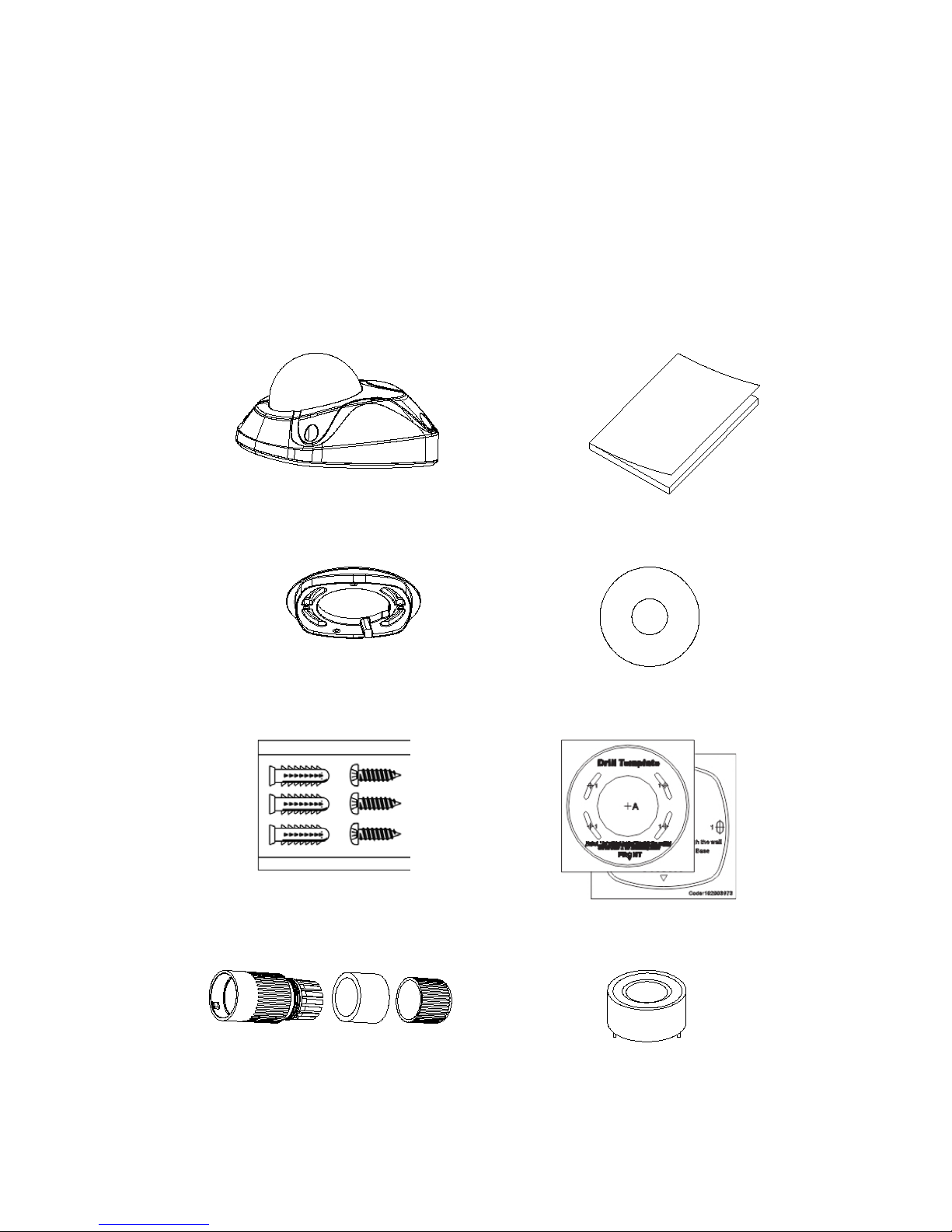
Package contents
Check the package and contents for visible damage. If any
components are damaged or missing, do not attempt to use the
unit; contact the supplier immediately. If the unit is returned, it
must be shipped back in its original packaging.
IP wedge camera
Installation manual
Converter pan
Configuration CD
Anchors and screws
Mounting templates
Water joint: Ethernet
Lens alignment tool
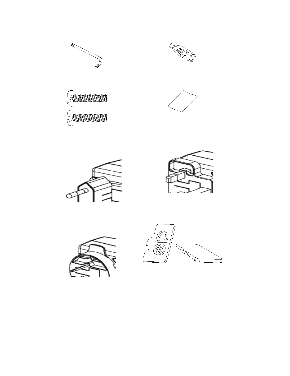
10 Installation Guide
Hex wrench
12 VDC connector
Screws C: M4×8, 2pcs
WEEE and battery disposal
Power supply with
European plug
Power supply with UK plug
Power supply with
Australian plug
SD card
 Loading...