

Page 1

TruVision
Series 6 IP
Camera Installation
Guide
P/N 1073465-EN • REV B • ISS 13DEC18
Page 2
Copyright
Disclaimer
Trademarks and
patents
Manufacturer
Certification
© 2018 United Technologies Corporat ion,
Interlogix is part of UTC Climate, Controls & Sec urity, a
unit of United Technologies Corporati on. All rights
reserved.
Information in this document is subject to change
without notice. No part of this document may be
reproduced or transmitted in any form or by any means,
electronic or mechanical, for any purpose, without the
express written permission of UTC Fire & Securit y
Americas Corporation, Inc.
Trade names used in this document may be trademarks
or registered trademarks of the manufact urers or
vendors of the respective products.
Interlogix
2955 Red Hill Avenue, Costa Mesa, CA 92626-5923,
USA
Authorized EU manufacturing representat ive:
UTC Fire & Security B.V.
Kelvinstraat 7, 6003 DH Weert, The Net herlands
FCC compliance
Class A: This equipment has been tested and found to
comply with the limits for a Class A digital device,
pursuant to part 15 of the FCC Rules. These limits are
designed to provide reasonable protecti on against
harmful interference when the equipm ent is operated in
a commercial environment. This equipment generat es,
uses, and can radiate radio frequency energy and, if not
installed and used in accordance with the instruc tion
manual, may cause harmful interference t o radio
communications. Operation of this equipm ent in a
residential area is likely to cause harmful int erference in
which case the user will be required to correct the
interference at his own expense.
Page 3
FCC conditions
ACMA compliance
Canada
European Union
directives
This device complies with Part 15 of the FCC Rules.
Operation is subject t o the following two conditions:
(1) This device may not cause harmful interfer ence.
(2) This Device must accept any interference receiv ed,
including interferenc e that may cause undesired
operation.
Notice! This is a Class A product. In a dom estic
environment this product may cause radio interference
in which case the user may be required to take
adequate measures.
This Class A digital apparatus complies with CAN
ICES-003 (A)/NMB-3 (A).
Cet appareil numérique de la classe A est conform e à
la norme CAN ICES-003 (A)/NMB-3 (A).
This product and - if applicable - the supplied
accessories too are marked with "CE" and comply
therefore with the applicable harmoniz ed European
standards listed under the EM C Directive 2014/30/EU,
the RoHS Directive 2011/65/EU.
2012/19/EU (WEEE directive): Products marked with
this symbol cannot be disposed of as unsorted
municipal waste in the European Union. For proper
recycling, return this product to your local suppl ier upon
the purchase of equivalent new equipment, or dispose
of it at designated collection points. F or more
information see: www.recyclethi s.info.
2013/56/EU & 2006/66/EC (battery directi ve): This
product contains a battery that cannot be disposed of
as unsorted municipal waste in t he European Union.
See the product documentation for specifi c battery
information. The battery is marked with thi s symbol,
which may include lettering to indicat e cadmium (Cd),
lead (Pb), or mercury (Hg). For proper recycling, return
the battery to your supplier or to a designated coll ection
point. For more inf ormation see: www.recyclet his.info.
Installation Guide iii
Page 4
Product warnings and
disclaimers
THESE PRODUCTS ARE INTENDED FOR SALE TO
AND INSTALLATION BY QUALIFIED
PROFESSIONALS. UTC FIRE & SECURITY CANNOT
PROVIDE ANY ASSURANCE THAT ANY PERSON
OR ENTITY BUYING ITS PRODUCTS, INCLUDING
ANY “AUTHORIZED DEALER” OR “AUTHORIZED
RESELLER”, IS PROPERLY TRAINED OR
EXPERIENCED TO CORRECTLY INSTALL FIRE AND
SECURITY RELATED PRODUCTS.
For more information on warranty di sclaimers and
product safety information, please check
https://firesecurity products.com/policy/product-warning/
or scan the QR code:
Contact information
and manuals/ tools/
firmware
For contact information and to download the lat est
manuals, tools, and firmware, go to the web site of your
region.
Americas: www.interlogix.com
EMEA: www.firesecurityproducts.com
Manuals are available in sever al languages.
Australia/New Zealand: www.utcf s.com.au
Page 5
Safety instructions
These instructions are intended to ensure that user can use
the product correctly to avoid danger or property loss.
The precaution measures are divided into “Warnings” and
“Cautions”.
Warnings: Warning messages advise you of
hazards that could result in injury or loss of life.
They tell you which actions to take or to avoid in
order to prevent the injury or loss of life.
Cautions: Caution messages advise you of
possible equipment damage. They tell you which
actions to take or to avoid in order to prevent
damage.
Warnings
• When using thi s product, you must comply with the
electrical safety regulations of the country and region.
Please refer to the technical specifications for detailed
information.
• Input voltage should meet both the SELV (Safety Extra
Low Voltage) and the Limited Power Source with 24 VAC
or 12 VDC according to the IEC60950-1 standard. Please
refer to the technical specifications for detailed
information.
• Do not connect several devices to one power adapter as
adapter overload may cause over-heating or a fire
hazard.
Installation Guide 1
Page 6

• Please make sure that the plug is firmly connected to the
power socket. When the device is mounted on a wall or
ceiling, it should be firmly fixed to the surface.
• If smoke, odor or noise rises from the device, turn off the
power at once and unplug the power cable. Then please
contact the service center.
• Proper configuration of all passwords and other security
settings is the responsibility of the installer and/or enduser.
Cautions
• Make sure the power supply voltage is correct before
using the camera.
• Do not drop the camera or subject it to physical shock.
• Do not touch sensor modules with fingers. If cleaning is
necessary, use clean cloth with a bit of ethanol and wipe
it gently. If the camera will not be used for an extended
period, please replace the lens cap to protect the sensor
from dirt.
• Do not aim the camera at the sun or extra bright places.
Blooming or smearing may occur otherwise (which is not
a malfunction), and affect the endurance of sensor at the
same time.
• The sensor may be burned out by a laser beam, so when
any laser equipment is in using, make sure that the
surface of sensor will not be exposed to the laser beam.
• Do not place the camera in extremely hot, cold (the
operating temperature is-30°C ~+60°C, or -40°C ~ +60°C
if the camera model has an “H” in its suffix), dusty or
damp locations, and do not expose it to high
electromagnetic radiation.
2 Installation Guide
Page 7

• To avoid heat accumulation, good ventilation is required
for operating environment.
• Keep the camera away from liquid while in use.
• During delivery, the camera shall be packed in its original
packing, or packing of the same texture.
• Regular part replacement: a few parts (e.g. electrolytic
capacitor) of the equipment shall be replaced regularly
according to their average enduring time. The average
time varies because of differences between operating
environment and using history, so regular checking is
recommended for all the users. Please contact with your
dealer for more details.
• Improper use or replacement of the battery may result in
hazard of explosion. Replace with the same or equivalent
type only. Dispose of used batteries according to the
instructions provided by the battery manufacturer.
• If the product does not work properly, please contact your
dealer or the nearest service center. Never attempt to
disassemble the camera yourself. (We shall not assume
any responsibility for problems caused by unauthorized
repair or maintenance.)
Installation Guide 3
Page 8

Content
Introduction 6
Product overview 6
Contact information and manuals /tools /firmware 8
Installation 9
Installation environment 10
Package contents 11
Cable requirements 24
Camera description 25
Setting up the camera 33
IR illuminators 33
Accessing the Micro SD card 34
Mounting the bullet camera 34
Mounting the turret camera 40
Mounting the dome camera 47
Mounting the wedge camera 57
Using t he protective water resistant connector cover 61
Network access 65
Checking your web browser security level 65
Activating the camera 67
Using the camera with a TruVision recorder or another
system 70
Using the camera with TruVision Navigator 70
Specifications 71
TruVision IP fixed lens bullet cameras 71
TruVision IP motorized lens bullet cameras 71
4 Installation Guide
Page 9

TruVision IP fixed lens turret dome 72
TruVision IP motorized lens turret dome 73
TruVision IP fixed lens dome cameras 73
TruVision IP motorized lens dome cameras 74
TruVision IP fixed lens wedge cameras 75
Pin definitions 76
Installation Guide 5
Page 10

Introduction
Product overview
This is the installation guide for TruVision Series 6 IP camera
models:
TVB-5601 (2MPX IP fixed lens bullet camera)
TVB-5602 (4MPX IP fixed lens bullet camera)
TVB-5603 (8MPX IP fixed lens bullet camera)
TVB-5604 (2MPX IP motorized lens bullet camera)
TVB-5605 (4MPX IP motorized lens bullet camera)
TVB-5606 (8MPX IP motorized lens bullet camera)
TVT-5601 (2MPX IP fixed lens turret camera, gray)
TVT-5602 (2MPX IP fixed lens turret camera, white)
TVT-5603 (2MPX IP fixed lens turret camera, black)
TVT-5604 (4MPX IP fixed lens turret camera, gray)
TVT-5605 (4MPX IP fixed lens turret camera, white)
TVT-5606 (4MPX IP fixed lens turret camera, black)
TVT-5607 (8MPX IP fixed lens turret camera, gray)
TVT-5608 (2MPX IP motorized lens turret camera, gray)
TVT-5609 (4MPX IP motorized lens turret camera, gray)
6 Installation Guide
Page 11

TVT-5610 (4MPX IP motorized lens turret camera,
white)
TVT-5611 (8MPX IP motorized lens turret camera, gray)
TVD-5601 (2MPX IP fixed lens dome camera)
TVD-5602 (4MPX IP fixed lens dome camera)
TVD-5603 (8MPX IP fixed lens dome camera)
TVD-5604 (2MPX IP motorized lens dome camera)
TVD-5605 (4MPX IP motorized lens dome camera)
TVD-5606 (8MPX IP motorized lens dome camera)
TVW-5601 (2MPX IP fixed lens dome camera, 2.0 mm)
TVW-5602 (2MPX IP fi xed lens dome camera, gray)
TVW-5603 (2MPX IP fixed lens dome camera, white)
TVW-5604 (2MPX IP fixed lens dome camera, black)
TVW-5605 (4MPX IP fixed lens dome camera, gray)
You can download the software and the following manuals
from our web site:
TruVision Series 6 IP Camera Installation Guide
TruVision Series 6 IP Camera Configuration Manual
Installation Guide 7
Page 12

Contact information and manuals /tools
/firmware
For contact information and to download the latest manuals,
tools, and firmware, go to the web site of your region:
Americas: www.interlogix.com
EMEA: www.firesecurityproducts.com
Australia/New
Zealand:
Manuals are available in several
languages.
www.utcfs.com.au
8 Installation Guide
Page 13

Installation
This section provides information on how to install the
cameras.
Before you start:
• Make sure the device in the package is in good condition
and all the assembly parts are included.
• The standard power supply is 12 VDC or PoE (802.3 af).
Please make sure your power supply matches with your
camera.
• Make sure all the related equipment is power-off during
the installation.
• Check the specification of the products for the installation
environment.
• Make sure that the wall is strong enough to withstand
four times the weight of the camera and the bracket.
For the camera that supports IR, you are required to pay
attention to the following precautions to prevent IR reflection:
• Dust or grease on the dome cover will cause IR
reflection. Please do not remove the dome cover film until
the installation is finished. If there is dust or grease on the
dome cover, clean the dome cover with clean soft cloth
and isopropyl alcohol.
• Make sure that there is no reflective surface too close to
the camera lens. The IR light from the camera may reflect
back into the lens causing reflection.
• The foam ring around the lens must be seated flush
against the inner surface of the bubble to isolate the lens
from the IR LEDS. Fasten the dome cover to camera
body so that the foam ring and the dome cover are
attached seamlessly.
Installation Guide 9
Page 14

Installation environment
When installing your product, consider these factors:
• Electrical: Install electrical wiring carefully. It should be
done by qualified service personnel. Always use a proper
PoE switch or a 12 VDC UL listed Class 2 or CE certified
power supply to power the camera. Do not overload the
power cord or adapter.
• Ventilation: Ensure that the location planned for the
installation of the camera is well ventilated.
• Temperature: Do not operate the camera beyond the
specified temperature, humidity or power source ratings.
The operating temperature of the camera without heater
is between -30 to +60°C (-22 to 140°F). Humidity is below
90%. For the outdoor cameras that feature built-in
heaters, the operating temperature range is -40 to 60°C
(-40 to140°F)
• Moisture: Do not expose the camera to rain or moisture
or try to operate it in wet areas. Turn the power off
immediately if the camera is wet and ask a qualified
service person for servicing. Moisture can damage the
camera and also create the danger of electric shock.
• Servicing: Do not attempt to service this camera
yourself. Any attempt to dismantle or remove the covers
from this product will invalidate the warranty and may
also result in serious injury. Refer all servicing to qualified
service personnel.
• Cleaning: Do not touch the sensor modules with fingers.
If cleaning is necessary, use a clean cloth with some
ethanol and wipe the camera gently. If the camera will not
be used for an extended period of time, put on the lens
cap to protect the sensors from dirt.
10 Installation Guide
Page 15
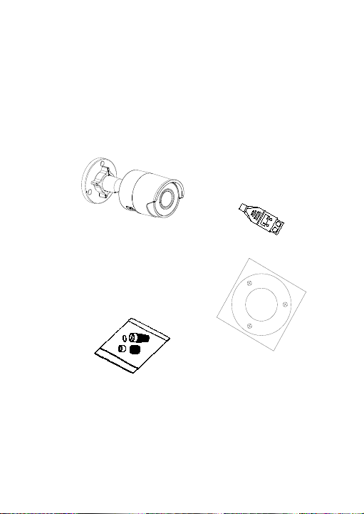
Package contents
Hole
Hole
Hole
Ceiling Mounting
Check the package and contents for visible damage. If any
components are damaged or missing, do not attempt to use
the unit; contact the supplier immediately. If the unit is
returned, it must be shipped back in its original packaging.
IP fixed lens bullet camera
• Camera
• 12 VDC connector:
Two terminal
connector with
positive and negative
indicators.
• Protective water
resistant RJ45
connector cover:
• Drill template
Provides water
resistance to network
cable connector.
Installation Guide 11
Page 16
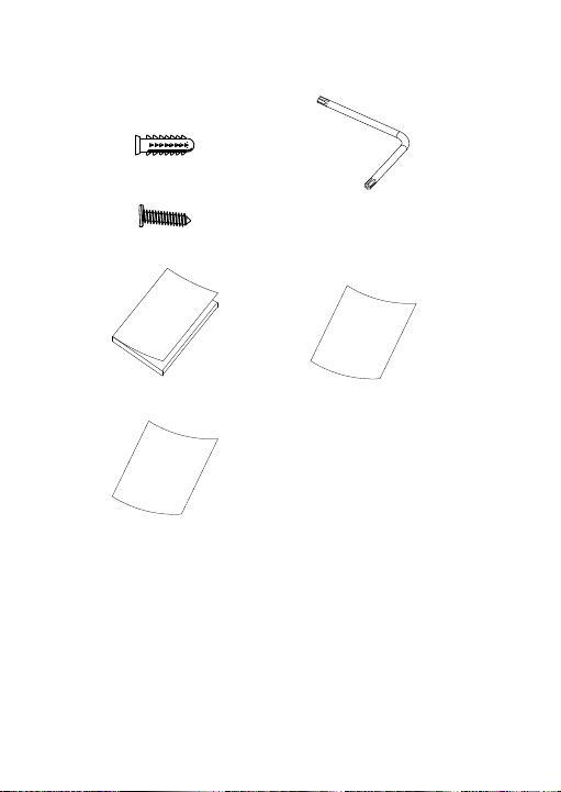
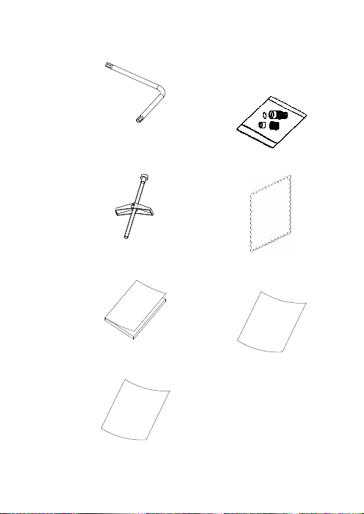
• Screws
Drywall anchor
7.5 × 24.5 mm (3 pcs)
Screw
M4 × 25 mm (3 pcs)
• Installation guide
• Torx wrench
• Equipment disposal
sheet
• Battery disposal sheet
12 Installation Guide
Page 17
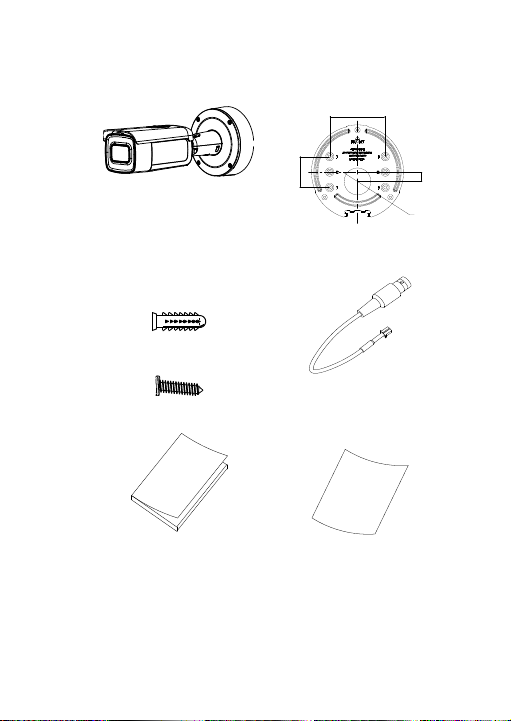
IP motorized lens bullet camera
46 mm
(1.81 in.)
83.5 mm (3.29 in.)
14 mm
(0.55 in.)
40 mm
(1.57 in.)
• Camera
• Screws
Drywall anchor
7.5 × 24.5 mm (4 pcs)
Screw
M4 × 25 mm (4 pcs)
• Installation guide
• Mounting adapter plate
• Video test cable
• Equipment disposal
sheet
Installation Guide 13
Page 18
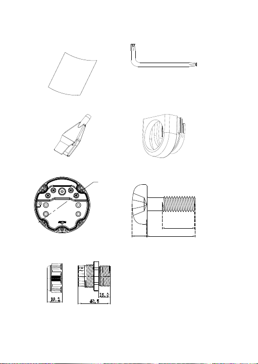
• Battery disposal
(mm)
144.1 mm
(5.67 in
2 mm
(0.08 in.)
3.5 mm
(0.14 in.)
9 mm (0.35 in.)
sheet
• Torx wrench
• Cable routing tool
• Adapter ring for G3/4
• Back box
• G3/4 cable adapter
• Screws for the back
box
14 Installation Guide
Page 19
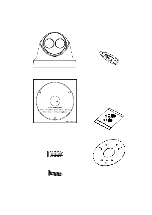
IP fixed lens turret camera
• Camera
• 12 VDC connector:
Two terminal
connector with
positive and negative
indicators.
• Camera drill template • Protective water
resistant RJ45
connector cover:
Provides water
resistance to
network cable
connector.
• Screws
Drywall anchor
7.5 × 24.5 mm (3 pcs)
• Adapter plate
Screw
M4 × 25 mm (3 pcs)
Installation Guide 15
Page 20
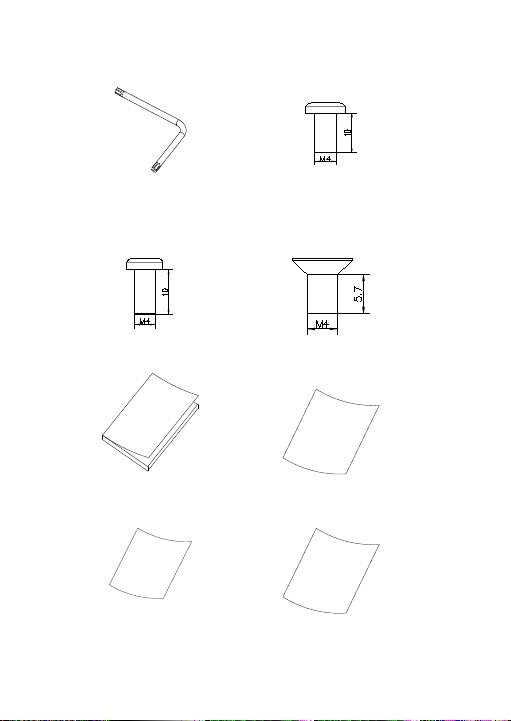
• Torx wrench
• Screw PM4 × 8
(3pcs)
• Screw PM6-32 × 10
(4 pcs, used to attach
the turret camera to a 2
Gang electrical box)
• Screw KM4 × 8
(4 pcs, used to
attach the adapter to
the brackets)
• Installation guide
• Equipment disposal
sheet
16 Installation Guide
• Installation guide of
• Battery disposal
the turret adapter
sheet
Page 21
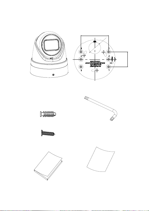
IP motorized lens turret camera
83.5
mm (3.29 in.)
36 mm
(1.42 in.)
46 mm (1.81 in.)
• Camera
• Mounting adapter plate
• Screws
Drywall anchor
7.5 × 24.5 mm (4
pcs)
Screw
M4 × 25 mm (4 pcs)
• Torx wrench
• Installation
guide
Installation Guide 17
• Battery disposal sheet
Page 22
• Equipment
disposal sheet
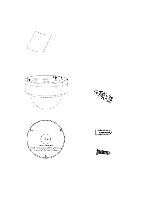
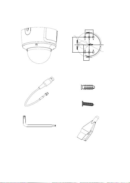
IP fixed lens dome camera
• Camera
• Camera drill template
• 12 VDC connector:
Two terminal connector
with positive and
negative indicators.
• Screws
Drywall anchor
7.5 × 24.5 mm (3 pcs)
Screw
M4 × 25 mm (3 pcs)
18 Installation Guide
Page 23
• Torx wrench
• Toggle bolt (3 pcs)
• Water joint: Provides
water resistance to
network cable
connector.
• Gray cloth
• Installation guide
• Equipment disposal
sheet
• Battery disposal sheet
Installation Guide 19
Page 24
IP motorized lens dome camera
46
mm (1.81 in.)
83.5 mm (3.29 in.)
45 mm
(1.77
in.)
140 mm
(
5.51
in.)
31
.5 mm
(1
.24
in.)
• Camera
• Mounting adapter plate
• Video test cable
• Screws
Drywall anchor
7.5 × 24.5 mm (4 pcs)
Screw
M4 × 25 mm (4 pcs)
• Torx wrench
• Cable routing tool
20 Installation Guide
Page 25
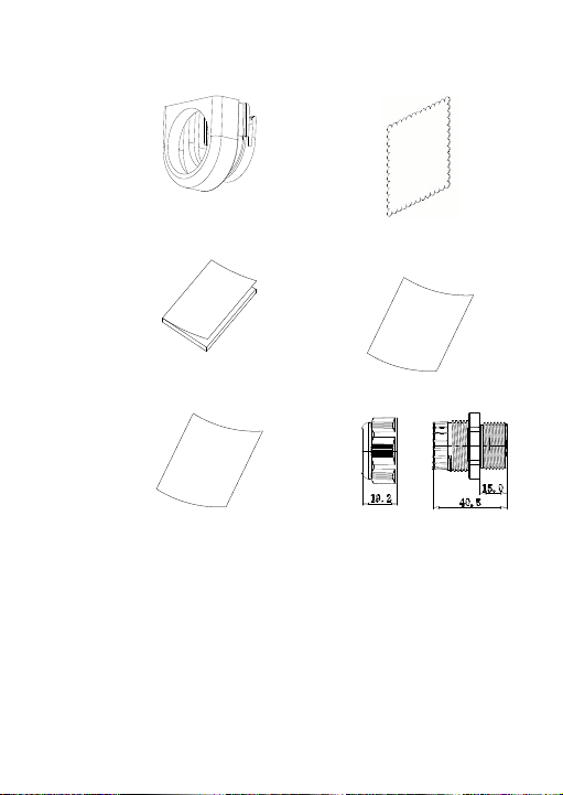
• Adapter ring for G3/4
(mm)
• Gray cloth
• Installation guide
• Equipment disposal
sheet
• Battery disposal sheet • G3/4 cable adapter
Installation Guide 21
Page 26
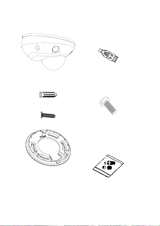
IP fixed lens wedge camera
• Camera
• Screws
Drywall anchor
7.5 × 24.5 mm (3 pcs)
Screw
M4 × 25 mm (3 pcs)
• Adapter plate
• 12 VDC connector:
Two terminal connector
with positive and
negative indicators.
• Screws: M4 × 8 (3 pcs)
Used for mounting the
wedge to the adapter
plate
• Protective water
resistant RJ45
connector cover:
Provides water
resistance to network
cable connector.
22 Installation Guide
Page 27

• Torx wrench
• Installation guide
• Gray cloth
• Equipment disposal
sheet
• Battery disposal sheet
Caution: Use direct plug-in UL listed power supplies marked
Class 2/CE certified or LPS (limited power source) of the
required output rating as listed on the unit.
Installation Guide 23
Page 28

Caution: Risk of explosion if the battery is replaced by an
IP
IP
IP
IP motorized lens turret camera:
IP fixed lens dome camera:
IP
IP fixed lens wedge camera
incorrect type. Dispose of used batteries according to the
instructions.
Cable requirements
For proper operation, adhere to the following cable and power
requirements for the cameras. Category 5 cabling or better is
recommended. All network cabling must be installed according
to applicable codes and regulations. Table 1 lists the
requirements for the cables that connect to the camera.
Table 1: Recommended power requirements
fixed lens bullet camera: 12 VDC or PoE (802.3af)
motorized lens bullet camera: 12 VDC or PoE+ (802.3at)
fixed lens turret camera: 12 VDC or PoE (802.3af)
12 VDC or PoE (802.3af)
12 VDC or PoE (802.3af)
motorized lens dome camera: 12 VDC or PoE (802.3af)
: 12 VDC or PoE (802.3af)
24 Installation Guide
Page 29

Camera description
port
Figure 1: IP fixed lens bullet camera
1. Adjustable bracket
2. Back housing
3. Front housing
4. Lens
5. Sunshield
6. Ethernet RJ45 PoE
Note: To reset the camera to default settings, press and hold
the RESET button and power on the camera. After the camera
has started up, hold the RESET button for an additional 20
seconds.
7. 12 VDC power
8. Reset button
9. Micro SD card slot
10. Grounding screw
11. Serial port (factory use)
Installation Guide 25
Page 30

Figure 2: IP motorized lens bullet camera
in/mic in)
1. Alarm 1 input /1 output
(up to 12 VDC, 30 mA)
2. 12 VDC power
3. Ethernet RJ45 PoE
port
4. Audio 1 input (line
Note: To reset the camera to default settings, press and hold
the RESET button and power on the camera. After the camera
has started up, hold the RESET button for an additional 20
seconds.
5. Audio 1 outp ut (line
out)
6. Reset button
7. Micro SD card slot
8. 960H analog output
26 Installation Guide
Page 31

Figure 3: IP fixed lens turret camera
9
9
8
7
7
2MPx / 4MPx8MPx
9. Micro SD card slot
1. Lens assembly
2. Trim ring
3. Housing
4. Base
5. 12 VDC power
Note: To reset the camera to default settings, press and hold
the RESET button and power on the camera. After the camera
has started up, hold the RESET button for an additional 20
seconds.
Installation Guide 27
6. Ethernet RJ45 PoE
port
7. Reset button
8. Serial port (factory
use)
Page 32

Figure 4: IP motorized turret camera
15
16
17
13. GND for alarm input
1. Housing
2. Black rubber protective
cover
3. Rubber inserts
4. Removable cable
access door
5. Trim ring
28 Installation Guide
9. Audio 1 input (line
in/mic in)
10. Audio 1 output (line
out)
11. GND for alarm output
12. Alarm 1 output (up to
12VDC, 30mA)
Page 33

6. GND for 12 VDC
port
power
7. Positive pole for 12
VDC power
8. Ethernet RJ45 PoE
Note: To reset the camera to default settings, press and hold
the RESET button and power on the camera. After the camera
has started up, hold the RESET button for an additional 20
seconds.
14. Alarm 1 input
15. Reset button
16. Micro SD card slot
17. SD card cover
Installation Guide 29
Page 34

Figure 5: IP fixed lens dome camera
9
10
10. Reset button
1. 12 VDC power
2. Audio 1 input (line in/mic
in) / 1 output (line out)
3. Alarm 1 input/1 output (up
to 12 VDC, 30 mA)
4. Ethernet RJ45 PoE port
Note: To reset the camera to default settings, press and hold
the RESET button and power on the camera. After the camera
30 Installation Guide
5. Base
6. Dome liner
7. Lens
8. Housing cover
9. SD card slot
Page 35

has started up, hold the RESET button for an additional 20
5. 12 VDC power
seconds.
Figure 6: IP motorized lens dome camera IP motorized
lens dome camera parts
1. Housing cover
2. Audio 1 input (line in/mic
3. Alarm 1 input/1 output (up
4. Ethernet RJ45 PoE port
Note: To reset the camera to default settings, press and hold
the RESET button and power on the camera. After the camera
has started up, hold the RESET button for an additional 20
seconds.
For a proper fit, the access panel to the SD card and Reset
button needs to be installed with the thicker section of the
panel towards the base of the dome.
Installation Guide 31
in) / 1 output (line out)
to 12 VDC, 30 mA)
6. Lens assembly
7. Reset button
8. Micro SD card slot
9. Back box
10. Rubber seal
11. 960H output
Page 36

Figure 7: IP fixed lens wedge camera
1 output
1. Housing cover
2. Lens assembly
3. Camera assembly
4. MIC (microphone)
5. Reset button
6. Micro SD card slot
7. Audio 2 inputs. Line in or
MIC (built-in microphone) /
32 Installation Guide
8. Alarm 1 input/1
output
9. 12 VDC power
10. Ethernet RJ45 PoE
port
11. IR illuminators
12. Ground
Page 37

Note: To reset the camera to default settings, press and hold
the RESET button and power on the camera. After the camera
has started up, hold the RESET button for an additional 20
seconds.
Setting up the camera
Note: If the light source where the camera is installed
experiences rapid, wide-variations in lighting, the camera may
not operate as intended.
To quickly put the camera into operation:
1. Prepare the mounting surface.
2. Mount the camera on the mounting surface using the
appropriate fasteners. See “Mounting the wedge camera”
on page 57.
3. Set up the camera’s network and streaming parameters
so that the camera can be controlled over the network.
For further information, please refer to the “TruVision
Series 6 IP Camera Configuration Manual”.
4. Program the camera as appropriate for its location. For
further information, please refer to the “TruVision Series 6
IP Camera Configuration Manual”.
IR illuminators
The camera’s built-in IR illumination provides high-quality
video in low-light environments, even when there is no other
illumination available.
You can configure the IR illumination using a web browser or a
client software, such as TruVision Navigator. If the function is
enabled, the IR light is On when the camera enters night
(black and white) mode. If disabled, the IR light is always Off.
Installation Guide 33
Page 38

The visible IR range may vary due to multiple factors such as
weather, IR reflection level of objects in frame, lens
adjustment, and camera settings. Please refer to the camera
datasheet for the standard IR range.
Note: Avoid installing the IR camera closely facing a solid
object such as a tree or wall. The reflection will cause overexposure and loss of visibility of detail in field of view.
Accessing the Micro SD card
Insert a Micro SD card with up to 128GB to use the camera as
an additional recording device, or as a backup in case of
failure of communication with the network video recorder (see
Figure 1 on page 25). The card is not supplied with the
camera.
Recorded video and log files can be accessed via the web
browser or via TruVision Navigator.
Mounting the bullet camera
Mount the camera on a ceiling or wall.
To mount the IP fixed lens bullet camera:
1. Use the supplied template to mark out the mounting area.
Drill the screw holes on the ceiling or wall. If you need to
route the cables from the camera base, drill a cable hole
in the ceiling or wall.
2. Secure the mounting base to the ceiling or wall using the
three mounting screws and drywall anchors.
34 Installation Guide
Page 39

3. Loosen the large nut at the base of the mounting bracket
to adjust the camera’s viewing angle.
Pan direction: 0 to 360° adjustable
Tilt direction: 0 to 90° adjustable
Rotate direction: 0 to 360° adjustable
4. Adjust the lens to the desired surveillance angle. Tighten
the adjustable nuts to complete the installation.
To mount the IP motorized lens bullet camera:
1. Drill screw holes in the wall/ceiling according to the holes
1 on the mounting adapter plate.
Installation Guide 35
Page 40

2. Secure the mounting adapter plate to the wall/ceiling with
the screws.
3. Loosen the screws to remove the back box.
36 Installation Guide
Page 41

4. Route the cables through the sealing plugs in the back
box.
a) Pierce the sealing plugs on the back box.
b) Thread cables through the sealing plugs.
Note:
• For RJ45 network interface, use the supplied cable
routing tool.
• For the audio interface, first thread the audio cable
through the sealing plug and then connect the audio
connector to the cable.
Installation Guide 37
Page 42

1. Drag the sealing plug
back
2. Valgus
3. Secure the back box in the wall/ceiling with screws.
4. Hook the camera to the back box with the safety lanyard
and connect the cables to the camera.
38 Installation Guide
Page 43

5. Secure the camera to the back box with the screws.
6. Adjust the viewing angle.
3-axis adjusting (pan/tilt/rotation) allows you to adjust for
optimum camera rotation and placement. Follow the
steps below to adjust the viewing angle.
a) Loosen the lock screw using the supplied wrench.
Installation Guide 39
Page 44

b) Adjust the view angle of the camera. The adjusting
Lock screw
range of the panning is from 0° to 360°, the tilting is
from 0° to 90° and the rotation is from 0° to 360°.
c) Tighten the lock screw.
Mounting the turret camera
To mount the fixed lens turret camera on a surface:
1. Place the drill template (supplied) on the surface where
the camera is to be mounted. Drill mounting holes in the
surface using the holes labeled number “1” on the drill
template.
To route the cable harness through the mounting surface,
cut a cable access hole in the mounting surface,
referencing the letter “A” on the drill template. Skip this
step if you want to route the cables on the surface.
40 Installation Guide
Page 45

An adapter plate is provided if installing the turret camera
to a wall mount or other accessory. Install the adapter
plate to the accessory with three PM4X8 screws,
referencing number “2”.
2. Rotate the trim ring counterclockwise to remove it from
the camera.
3. Route the cables directly out of the base of the camera.
4. Install the camera on the m ounting surface using the
supplied hardware.
5. Connect the corresponding power and network cables.
6. Adjust the lens.
a) Loosen the locking screw using a Torx screw driver.
Installation Guide 41
Page 46

b) Rotate the lens assembly to adjust the pan angle.
Rotate the lens assembly to adjust the tilt angle.
c) Tighten the Torx screw to secure the lens at the
desired surveillance angle.
Torx screw
7. Attach the trim ring to the camera and rotate it clockwise
to secure it.
42 Installation Guide
Page 47

To mount the motorized lens turret camera on a
ceiling or wall:
1. Using the turret adapter plate, mark the mounting holes
for the plate. Use the four holes labeled with the number
1.
2. Secure the mounting adapter to the mounting surface
with the supplied screws.
Installation Guide 43
Page 48

Front
3. Hook the camera to the adapter with the safety lanyard.
Safety
lanyard
Connector
access cover
4. To access the connectors, loosen the two screws using
the Torx wrench and lift up on the access cover. The
black rubber insert at the edge of the access cover is
required to maintain the IP67 rating. Only remove the
plugs that cover the access ports required to provide
44 Installation Guide
Page 49

access for the cables that will be connected to the
Black rubber insert
camera.
Note:
When routing the cables, remove the whole rubber
sealing, then remove the sealing pillar, and then insert
the wire. Otherwise, keep the sealing plug intact.
5. Once all the cable connections are made, lower the
access cover and tighten the Torx screws. Line up the
turret with the mounting plate, there is an arrow and the
word FRONT referenced on the turret base and mounting
plate. Line up the three Phillips screws that are located
on the access cover with the three slots in the adapter
plate. Rotate the turret clockwise as far is the turret will
travel. Tighten the locking Torx screw at the base of the
turret.
Installation Guide 45
Page 50

Locking Torx screw
6. Adj ust the lens position.
Lens adjustment Torx screw
a) To adjust the lens position, remove the decorative
trim ring by rotating the ring towards the unlocked
position (see reference on the trim ring). Loose n the
lens adjustment Torx screw that is now visible.
b) Rotate the lens assembly to adjust the pan tilt angle.
c) Tighten the lens adjustment screw to secure the lens
at the desired surveillance angle.
46 Installation Guide
Page 51

0°~360°
0°~360°
0°~75°
7. Reinstall the trim ring on the camera, and rotate it
clockwise to secure.
To mount the motorized lens turret camera on a wall:
Please refer to the installation guide provided with the TVDCB6 mounting kit for instructions on mounting the motorized
lens turret camera to the wall.
Mounting the dome camera
To mount the fixed lens dome camera on a ceiling or
wall using a wall mount:
1. Place the drill template (supplied) on the surface where
the camera is to be mounted. Drill mounting holes in the
surface using the holes labeled number “1” on the drill
template.
To route the cable harness through the mounting surface,
and cut a cable access hole in the mounting surface,
Installation Guide 47
Page 52

referencing the letter “A” on the drill template. Skip this
step if you want to route the cables on the surface.
2. Using the supplied Torx wrench, remove the dome
bubble assembly.
Screw
48 Installation Guide
Page 53

3. Install the dome on the mounting surface using the
supplied hardware.
4. Loosen the tilt adjust screws (see image below) and
adjust the tilt position of the lens assembly within a range
of 75 degrees. Retighten the tilt adjust screws.
Rotate the dome liner to adjust the pan position within a
range of 355 degrees. Rotate the lens assembly (0 to
355°) to obtain the desired surveillance angle.
Installation Guide 49
Page 54

5. (Optional) If using a micro SD card (not included):
To remove the SD card, push the micro SD card forward.
The micro SD card will spring out.
SD slot
6. Reinstall the dome housing and tighten the Torx screws.
50 Installation Guide
Page 55

To mount the motorized lens dome camera on a
ceiling:
1. Lift the camera body to separate it from the back box and
the mounting adapter plate.
2. Separate the back box and the mounting adapter plate
from each other.
3. Unscrew the bubble from the camera body.
Installation Guide 51
Page 56

4. Mark four screw holes at desired mounting location using
the holes labeled number “2” on the mounting adapter
plate.
5. Secure the mounting adapter plate to ceiling with the four
supplied screws.
Note: Use expansion screws for a concrete ceiling and
self-tapping screws for a wooden ceiling.
52 Installation Guide
Page 57

6. Route the cables through the sealing plugs in the back
box.
a) Pierce the sealing plugs on the back box.
b) Thread cables through the sealing plugs.
Note:
• For RJ45 network interface, use the supplied cable
routing tool.
• For the audio interface, first thread the audio cable
through the sealing plug and then connect the audio
connector to the cable.
Installation Guide 53
Page 58

1. Drag the sealing
plug back
2. Valgus
7. Align t he “FRONT” marks on the back box and mounting
adapter plate. Secure the back box to the mounting
adapter plate with three screws.
54 Installation Guide
Page 59

8. Hang the camera body on the safety lanyard.
9. Connect the cables to corresponding plugs on the
camera base.
10. Fix the camera body to the back box with three screws.
Installation Guide 55
Page 60

0°~355°
0°~355°
0°~75°
11. Loosen the tilt adjust screws and adjust the tilt position of
the lens assembly within a range of 75 degrees.
Retighten the tilt adjust screws. Rotate the dome liner to
adjust the pan position within a range of 355 degrees.
Rotate the lens assembly (0 to 355°) to obtain the desired
surveillance angle.
56 Installation Guide
Page 61

12. Reattach the bubble back to the camera body and tighten
the Torx screw
To mount the motorized lens dome camera on a wall:
Please refer to the installation guide provided with the TVDCB7 mounting kit for instructions on mounting the motorized
lens dome camera to the wall.
Mounting the wedge camera
To mount the fixed lens wedge camera on a surface:
1. Use the supplied template to mark out the mounting area.
Drill mounting holes in the surface using the holes
labeled number “1” on the drill template.
To route the cable harness through the mounting surface,
cut a cable access hole in the mounting surface,
referencing the letter “A” on the drill template. Skip this
step if you want to route the cables on the surface.
Installation Guide 57
Page 62

2. Secure the adapter plate to the mounting surface using
Knocko ut
the drill template.
Note: If required, remove the knockout on the side of the
adapter plate to allow for cable access.
3. Loosen the Torx screws with a Torx wrench (supplied) to
remove the bubble assembly.
58 Installation Guide
Page 63

4. Mount the camera base to the adapter plate or directly to
the mounting surface.
5. Loosen the locking screw, located beside the RESET
button using the Phillips screwdriver. Adjust the view
angle of the camera. The adjusting range of the panning
is from -30° to 30°, the tilting is from 0° to 75° and the
rotation is from 0° to 360°. If required, loosen the locking
screw further to facilitate rotation.
Locking screw
Installation Guide 59
Page 64

6. Reattach the bubble assembly to the camera base.
60 Installation Guide
Page 65

Using the protective water resistant
①
②
③
④
⑤
⑥
⑦
1
2
3
4
5
6
7
connector cover
When installing a camera outdoors, it is recommended that the
supplied protective water resistant RJ45 connector cover be
used. Additional protection can be achieved by adding
weather resistant tape, not supplied.
Figure 8: Protective water resistant RJ45 connector cover
components
. RJ45 connector on the cable har ness
. Rubber washer
. RJ45 network plug
. Protective connector sleeve
. Rubber gasket
. Screw cap
. Network cable from router/switch
To install the protective water resistant RJ45
connector cover:
1. The RJ45 connector will not fit through the protective
cover components. The cover assembly components
should be placed on the network cable prior to crimping
Installation Guide 61
Page 66

on the RJ45 plug. Feed the network cable ⑦ through the
screw cap ⑥, rubber gasket ⑤ (the flat portion of the
rubber gasket goes towards the screw cap), and the
protective connector sleeve ④ in the order shown in
Figure 8.
2. Crimp an RJ-45 network plug ③onto the end of the cable,
ensuring that the twisted pairs of wires are in the correct
order.
3. Place the rubber washer ② onto the mating end of the
RJ45 connector on cable harness ①.
4. Insert the RJ45 network plug ③ into the RJ45 connector
①.
5. Slide the rubber gasket ⑤ i nto the protective cover
sleeve ④, and secure/tighten the screw cap ⑥ onto the
protective connector sleeve ④.
6. Align the snap ridges inside protective cover sleeve④
with the ridges inside of the RJ45 connector ①. Rotate
the protective cover sleeve to tighten up against the RJ45
connector ①, as shown below.
62 Installation Guide
Page 67

a) Insert into
Cable connector
Align the snap and notch
b) Secure with .
Camera Switch/Router
To install the weather resistant tape (not supplied):
1. Tightly wrap the tape around the RJ45 connector, as
shown below. Keep in mind that the tape will stretch as
you are wrapping the connector.
Installation Guide 63
Page 68

Note: Make sure that all bare wires are all firmly wrapped
with the tape.
2. Press down on the tape, at each end of the connector to
ensure a weather resistant seal.
Press
3. Also wrap weather resistant tape around any cable that
that has bare wires, as shown below.
Note: Make sure that all the bare wires are firmly
wrapped with weather resistant tape.
3. Press down on the tape to ensure a weather resistant
seal.
64 Installation Guide
Page 69

Press
Network access
This guide explains how to configure the camera over the
network with a web browser.
TruVision IP cameras can be configured and controlled using
Microsoft Internet Explorer (IE) and other browsers. T he
procedures described use Microsoft Internet Explorer web
browser.
Checking your web browser security level
When using the web browser interface, you can install ActiveX
controls to connect and view video using Internet Explorer.
However, you cannot download data, such as vi deo and
images due to the increased security measure. Consequently
you should check the security level of your PC so that you are
able to interact with the cameras over the web and, if
necessary, modify the Active X settings.
Configuring IE ActiveX controls
You sho uld co nfirm the ActiveX settings of your web browser.
Installation Guide 65
Page 70

To change the web browser’s security level:
1. In Internet Explorer, click Internet Options on the Tools
menu.
2. On the Security tab, click the zone to which you want to
assign a web site under “Select a web content zone to
specify its security settings”.
3. Click Custom Level.
4. Change the ActiveX controls and plug-ins options that
are signed or marked as safe to Enable. Change the
ActiveX controls and plug-ins options that are
unsigned to Prompt or Disable. Click OK.
— or —
Under Reset Custom Settings, click the security level
for the whole zone in the Reset To box, and select
Medium. Click Reset.
Then click OK to the Internet Options Security tab
window.
5. Click Apply in t he Internet Options Security tab window.
Windows Internet Explorer
Internet Explorer operating systems have increased security
measures to protect your PC from any malicious software
being installed.
To have complete functionality of the web browser interface
with Windows 7, 8, and 10, do the following:
• Run the browser interface as an administrator in your
workstation
• Add the camera’s IP address to your browser’s list of
trusted sites
66 Installation Guide
Page 71

To add the camera’s IP address to Internet Explorer’s
list of trusted sites:
1. Open Internet Explorer.
2. Click Tools, and then Internet Options.
3. Click the Security tab, and then select the Trusted sites
icon.
4. Click the Sites button.
5. Clear the “Require server verification (https:) for all sites
in this zone bo x”.
6. Enter the IP address in the “Add this website to the zone”
field.
7. Click Add, and then click Close.
8. Click OK in the Internet Options dialog window.
9. Connect to the camera for full browser functionality.
Activating the camera
When you first start up the camera, the Activation window
appears. You must define a high-security admin password
before you can access the camera. There is no default
password provided.
You can activate a password via a web browser and via
TruVision Device Manager (included on the CD to find the IP
address of the camera).
Activation via the web browser:
1. Power on the camera and connect the camera to the
network.
2. Input the IP address into the address bar of the web
browser, and click Enter to enter the activation interface.
Installation Guide 67
Page 72

Note:
The default IP address of the camera is 192.168.1.70.
For the camera to enable DHCP by default, you must
activate the camera via TruVision Device Manager.
Please refer to the following section, “Activation via
TruVision Device Manager”.
3. Enter the password in the password field.
Note: A valid password range must be between 8 and 16
characters. You can use a combination of numbers, lower
and upper case letters, and special characters : _ - , . * &
@ / $ ? Space. The password must contain characters
from at least two of these groups. We also recommend
that you reset your password regularly. For high security
systems, it is particularly recommended to reset the
password monthly or weekly for better protection.
4. Confirm the password.
5. Click OK to save the password and enter the live view.
68 Installation Guide
Page 73

Activation via TruVision Device Manager:
1. Run TruVision Device Manager to search for online
devices.
2. Check the device status from the device list, and select
the inactive device.
3. Enter the password in the password field, and confirm it.
Note: A valid password range must be between 8 and 16
characters. You can use a combination of numbers, lower
and upper case letters, and special characters : _ - , . * &
@ / $ ? Space. The password must contain characters
from at least two of these groups. We also recommend
that you reset your password regularly. For high security
systems, it is particularly recommended to reset the
password monthly or weekly for better protection.
4. Click OK to save the password.
A pop-up window appears to confirm activation. If
activation fails, confirm that the password meets the
requirements and try again.
Installation Guide 69
Page 74

5. Change the device IP address to the same subnet with
your computer by either modifying the IP address
manually or checking the check box of Enable DHCP.
6. Input the password and click the Save button to activate
your IP address modification.
Using the camera with a TruVision
recorder or another system
Please refer to the NVR/DVR user manuals for instructions on
connecting and operating the camera with these systems.
Using the camera with TruVision
Navigator
A camera must be connected to an Interlogix NVR in order to
be operated by TruVision Navigator. Please refer to the
TruVision Navigator user manual for instructions on operating
the camera with TruVision Navigator.
70 Installation Guide
Page 75

Specifications
Electrical
Voltage input
Power consumption
Miscellaneous
Connectors
Operating
Dimensions
Weight
Environmental rating
Electrical
Voltage input
Power consumption
TruVision IP fixed lens bullet cameras
12 VDC, PoE (IEEE 802.3af)
2MPX: Max. 7.5 W
4MPX: Max. 7.5 W
8MPX: Max. 8 W
12 VDC Power Input, Network Port
temperature -30 to +60 °C (-22 to +140°F)
70 × 155.03 mm
410 g (0.9 lbs.)
TruVision IP motorized lens bullet
cameras
12 VDC, PoE+ (IEEE 802.3at)
(PoE)
(2.76 x 6.1 in.)
IP67
2MPX: Max. 18 W
4MPX: Max. 18 W
8MPX: Max. 18 W
Installation Guide 71
Page 76

Miscellaneous
Connectors
Operating temperature
Dimensions
Weight
Environmental rating
Electrical
Voltage input
Power consumption
Miscellaneous
Connectors
Operating temperature
Dimensions
Weight
Environmental rating
12 VDC Power Input, Network Port
144.13 × 332.73 mm
1.74 kg (3.8 lbs.)
(PoE+), Audio In/Out, Alarm In/Out,
-30 to +60 °C (-22 to +140°F)
(5.7 x 13.1 in.)
IP67, IK10
TruVision IP fixed lens turret dome
12 VDC, PoE (IEEE 802.3af)
2MPX: Max. 7.5 W
4MPX: Max. 7.5 W
8MPX: Max. 8 W
12 VDC Power Input, Network Port
127.3 × 95.9 mm
620 g (1.37 lbs.)
(PoE)
-30 to +60 °C (-22 to +140 °F)
(5.01 × 3.78 in.)
IP67
72 Installation Guide
Page 77

TruVision IP motorized lens turret dome
Electrical
Voltage input
Audio
Power consumption
Miscellaneous
Connectors
Operating temperature
Dimensions
Weight
Environmental rating
Electrical
Voltage input
Power consumption
Miscellaneous
Connectors
12 VDC, PoE (IEEE 802.3af),
12 VDC Power Input, Network Port
135.8 × 145.5 mm
1.2 kg (2.6 lbs.)
In/Out, Alarm In/Out
2MPX: Max. 12.5 W
4MPX: Max. 12.5 W
8MPX: Max. 12.5 W
(PoE)
-30 to +60 °C (-22 to +140 °F)
(5.4 × 5.7 in.)
IP67, IK10
TruVision IP fixed lens dome cameras
12 VDC, PoE (IEEE 802.3af)
2MPX: Max. 7.5W
4MPX: Max. 7.5W
8MPX: Max. 9W
Network Port(PoE), Audio In/Out,
Alarm In/Out, 12 VDC Power Port
Installation Guide 73
Page 78

Operating temperature
-30 to +60 °C (-22 to 140°F)
Dimensions
Weight
Environmental rating
Electrical
Voltage input
Power consumption
Miscellaneous
Connectors
Operating temperature
Dimensions
Weight
Environmental rating
111 × 82.4 mm
500 g (1.1 lbs.)
(4.4 × 3.2 in.)
IP67, IK10
TruVision IP motorized lens dome
cameras
12 VDC, PoE (IEEE 802.3af)
2MPX: Max. 12W
4MPX: Max. 11.5W
8MPX: Max. 12W
Network Port(PoE), Audio In/Out,
153.4 × 133.1 mm
1.33 kg (2.9 lbs.)
Alarm In/Out, 12 VDC Power Port
-30 to +60 °C (-22 to 140°F)
(6.0 × 5.2 in.)
IP67, IK10
74 Installation Guide
Page 79

TruVision IP fixed lens wedge cameras
Electrical
Voltage input
Power
Miscellaneous
Connectors
Operating temperature
Dimensions
Weight
Environmental
12 VDC, PoE (IEEE 802.3af)
consumption 2MPX: Max. 10 W
12 VDC Power Input, Network Port
110 × 56.4 mm
395 g (0.87 lbs.)
rating IP66, IK8
4MPX: Max. 10 W
(PoE)
-30 to +60 °C (-22 to +140 °F)
(4.33 × 2.22 in.)
Installation Guide 75
Page 80

Pin definitions
There are eight wires on a standard UTP/STP cable and each
wire is color-coded. The following shows the pin allocation and
color of straight and crossover cable connection:
Figure 9: Straight-through cable
1 White/Orange
2 Orange Orange 2
3 Whi te-Green Whit e-Green 3
4 Blue Blue 4
5 White/Blue White/Blue 5
6 Green Green 6
7 White/Brown White/Brown 7
8 Brown Brown 8
Figure 10: Cross-over cable
1 White/Orange
2 Orange Orange 2
3 Whi te-Green White-Green 3
4 Blue Blue 4
5 White/Blue White/Blue 5
6 Green Green 6
7 White/Brown White/Brown 7
8 Brown Brown 8
Please make sure your connected cables have the same pin
assignment and color as above before deploying the cables in
your network.
76 Installation Guide
White/Orange 1
White/Orange 1
Page 81

Installation Guide 77
Page 82

Page 83

Page 84

 Loading...