

Page 1

TruVision Stainless Steel
PTZ Camera Installation
Guide
P/N 1073420-EN • REV A • ISS 30JAN18
Page 2

Page 3
Copyright
© 2018 United Technologies Corporat ion,
Trademarks
Trade names used in this document may be trademarks or
Manufacturer
Interlogix
Certificati on
FCC
Class A: This equipment has been tested and found to com ply with
FCC
This device complies with Part 15 of the FCC Rules. Operation is
ACMA
Notice! This is a Class A product. In a domestic envir onment this
Canada
This Class A digital apparatus complies with CAN I CES-003
European
This product and - if applicable - the supplied accessories too ar e
2012/19/EU (WEEE directive): Products marked with this symbol
Interlogix is part of UTC Climate, Controls & Sec urity, a unit of
United Technologies Corporation. All ri ghts reserved.
and patents
registered trademarks of the manufactur ers or vendors of the
respective products.
2955 Red Hill Avenue, Costa Mesa, CA 92626-5923, USA
Authorized EU manufacturing representat ive:
UTC Fire & Security B.V.
Kelvinstraat 7, 6003 DH Weert, The Net herlands
compli ance
compli ance
the limits for a Class A digital device, pursuant to part 15 of the
FCC Rules. These limits are designed to provide reasonable
protection against harmful interf erence when the equipment is
operated in a commercial environment. Thi s equipment generates,
uses, and can radiate radio frequency energy and, if not installed
and used in accordance with the instruction m anual, may cause
harmful interference to radio communi cations. Operation of this
equipment in a residential area is likely to cause harmful
interference in which case the user will be required t o correct the
interference at his own expense.
conditions
subject to the following two conditions:
(1) This device may not cause harmf ul interference.
(2) This Device must accept any int erference received, including
interference that may cause undesired operati on.
product may cause radio int erference in which case the user may
be required to take adequate measures.
(A)/NMB-3 (A). Cet appareil numérique de la classe A est
conforme à la norme CAN ICES-003 (A)/NMB-3 (A).
Union
marked with "CE" and comply therefore with the applicabl e
directives
harmonized European standards li sted under the EMC Directive
2014/30/EU, the RoHS Directiv e 2011/65/EU.
cannot be disposed of as unsorted municipal waste in the
European Union. For proper recycling, ret urn this product to your
local supplier upon the purchase of equiv alent new equipment, or
dispose of it at designated collection poi nts. For more information
see: www.recyclethis.info.
Page 4
Product
warnings
THESE PRODUCTS ARE INTENDED FOR SALE TO, AND
Contact
For contact information go to: www.interl ogix.com or
and
disclaimers
INSTALLATION BY, AN EXPERIENCED SECURITY
PROFESSIONAL. UTC FIRE & SECURITY CANNOT PROVIDE
ANY ASSURANCE THAT ANY PERSON OR ENTITY BUYING
ITS PRODUCTS, INCLUDING ANY “AUTHORIZED DEALER”, IS
PROPERLY TRAINED OR EXPERIENCED TO CORRECTLY
INSTALL SECURITY RELATED PRODUCTS.
For more information on warranty disclaimer s and product safety
information, please check
www.firesecurityproducts.com /policy/product-warning/ or scan the
following code:
information
and manuals
www.firesecurityproducts.com
To get translations f or this and other product manuals go to:
www.firesecurityproducts.com
Page 5

Content
Introduction 6
Product overview 6
Installation 6
Installation environment 6
Package contents 7
Camera description 10
Alarm input and output connections 11
SD memory card installation 11
Mounting the PTZ dome camera 12
Mounting the junction box 13
Using the camera with an Interlogix NVR or Hybrid DVR or
another system 15
Using the camera with TruVision Navigator 16
Access the camera over the internet 16
Specifications 19
PTZ camera 19
PTZ camera junction box 19
Pin definitions 20
Installation Guide 5
Page 6

Introduction
Product overview
This is the installation guide for the TruVision Stainless Steel
PTZ dome camera model:
• TVP-5201 (2MPX wall-mount PTZ dome camera, 23X)
Installation
This section provides information on how to install the
cameras.
Installation environment
When installing your product, consider these factors:
• Electrical: Install electrical wiring carefully. It should be
done by qualified service personnel. Always use a proper
PoE switch or a 24 VDC UL listed Class 2 or CE certified
power supply to power the camera. Do not overl oad the
power cord or adapter.
• Ventilation: Ensure that the location planned for the
installation of the camera is well ventilated.
• Temperature: Do not operate the camera beyond the
specified temperature, humidity, or power source ratings.
The operating temperature of the camera is between -40
to 60°C (-40 to140°F). Humidity is below 90%.
• Moisture: Do not expose the camera to rain or moisture
or try to operate it in wet areas. Turn the power off
immediately if the camera is wet and ask a qualified
6 Installation Guide
Page 7
service person for servicing. Moisture can damage the
camera and also create the danger of electric shock.
• Servicing: Do not attempt to service this camera
yourself. Any attempt to dismantle or remove the covers
from this product will invalidate the warranty and may
also result in serious injury. Refer all servicing to qualified
service personnel.
• Cleaning: Do not touch the sensor modules with fingers.
If cleaning is necessary, use a clean cloth with some
ethanol and wipe the camera gently. If the camera will not
be used for an extended period of time, put on the lens
cap to protect the sensors from dirt.
Package contents
Check the package and contents for visible damage. If any
components are damaged or missing, do not attempt to use
the unit; contact the supplier immediately. If the unit is
returned, it must be shipped back in its original packaging.
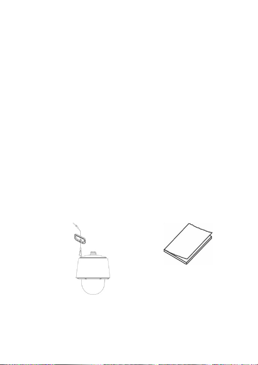
Package contents include the following:
Camera
Installation manual
Installation Guide 7
Page 8
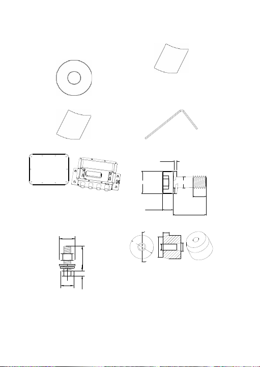
CD with configuration manual
13.6 mm
(0.54 in.)
1.6 mm
(0.06 in.)
5.85 mm
(0.23 in.)
5.5 mm
(0.22 in.)
5.0 mm
(0.20 in.)
10.7 mm (0.42 in.)
25 mm
(0.98 in.)
5.4 mm
(0.21 in.)
13 mm
(0.51 in.)
16 mm (0.63 in.)
6 mm (0.24 in.)
23.5 mm
(0.93 in.)
20.5 mm (0.81 in.)
A-A
A
A
6 mm (0.24 in.)
8 mm (0.31 in.)
and TruVision Device
Manager
Equipment disposal sheet
Battery disposal sheet
Junction box
Hex wrench
Screw A (10 pcs.)
Screw B (4 pcs.)
Blue sealing plug (3 pcs.)
8 Installation Guide
Page 9
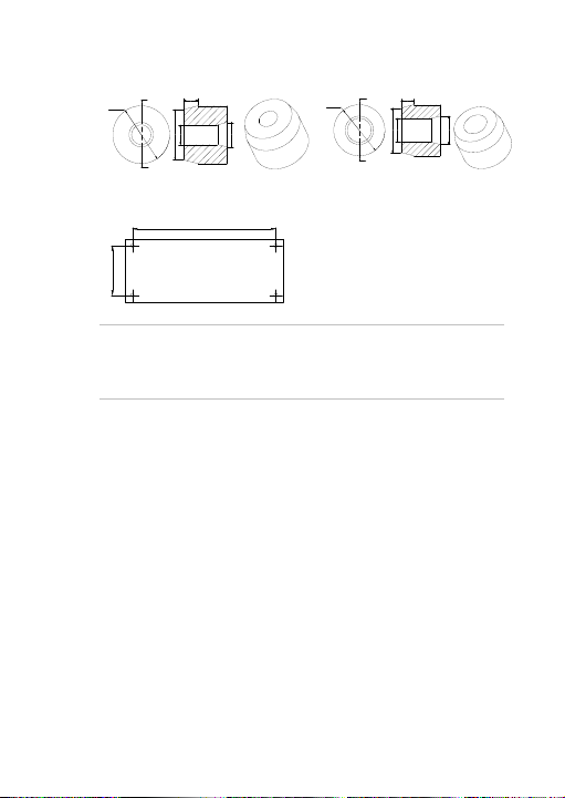
A-A
A
A
23.5 mm
(0.93 in.)
6 mm (0.24 in.)
20.5 mm (0.81 in.)
8 mm (0.31 in.)
10 mm (0.39 in.)
A-A
A
A
23.5 mm
(0.93 in.)
20.5 mm (0.81 in.)
6 mm (0.24 in.)
11 mm (0.43 in.)
13 mm (0.51 in.)
328 mm (12.91 in.)
113 mm (4.45 in.)
White sealing plug (3 pcs)
Black sealing plug (3 pcs)
Drill template – junction box
CAUTION: Use direct plug-in UL listed power supplies
marked Class 2/CE certified or LPS (limited power source) of
the required output rating as listed on the unit.
Installation Guide 9
Page 10
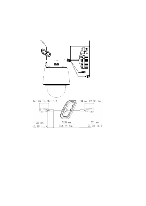
Camera description
VI
EOD
1200 mm (47.24 in.)
250 mm (9.84 in.)
①
②
③
④
⑤
⑥
⑦
7. Safety lanyard
Figure 1: PTZ camera description and connectors
1. 24V power supply (red 24 VAC,
yellow_green ground, black 24
VAC)
2. RS-485 (Orange R S-485+,
Yellow RS-485-)
3. Audio in (red_white) / Audio
output (blue_white)
10 Installation Guide
4. Alarm inputs (green, blue,
purple, gray, white,
black_white, brown_white) /
two alarm outputs (red, pink)
5. 960H analog output
6. RJ45 network cable
Page 11
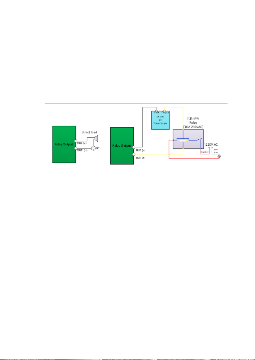
Alarm input and output connections
The alarm output can be used to turn on and off an external
alarm device. Connect a 30 VDC/1A external power supply to
the alarm output. If using an AC power supply, an external
relay must be used to prevent electric shock and damage to
the device. See Figure 2 below.
Figure 2: External alarm output
SD memory card installation
To install the SD memory card in the PTZ dome
1. Loosen the six hex screws on the bubble assembly.
Note: Do not remove the hex screws from the bubble
assembly. Loosen them enough to remove the bubble.
2. Carefully pull down the bubble assembly (2) to separate it
from the top enclosure (1), and remove the thin foam
shippi ng ring (3), and tape (4).
Installation Guide 11
Page 12
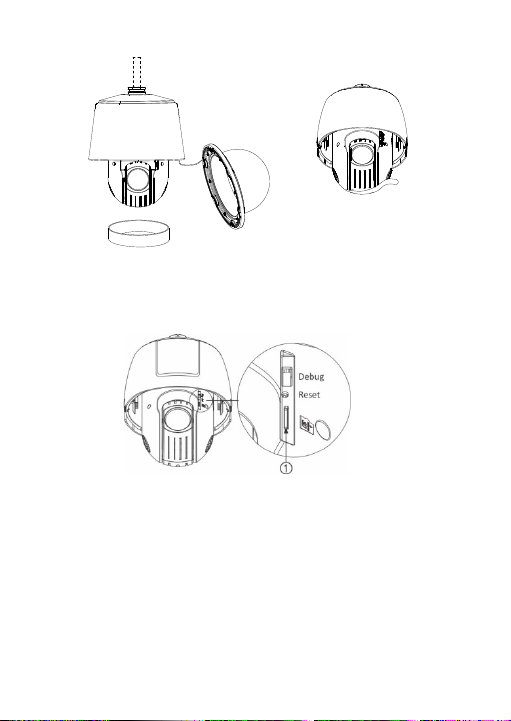
①
②
③
④
Note: Remove the thin foam shipping ring prior to
completing the installation.
3. Optional: Insert the memory card into the SD card slot (1)
until it clicks into place.
4. Reinstall the bubble assembly on the camera housing.
Mounting the PTZ dome camera
The TruVision Stainless Steel PTZ Wall Bracket (TVP-WBS,
not included) is required to wall-mount the PTZ camera, and
the TruVision Stainless Steel Pendant Bracket (TVP-PAS, not
included) is required to mount the PTZ camera to a ceiling.
12 Installation Guide
Page 13
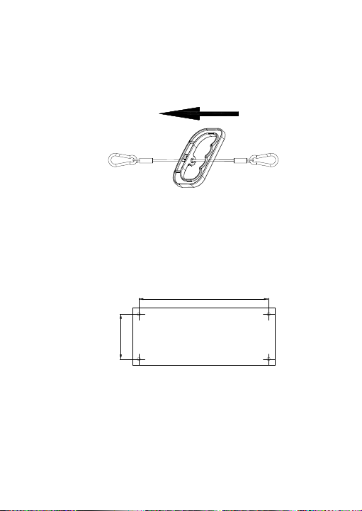
Refer to the installation guides provided with the TVP-WBS
328 mm (12.91 in.)
113 mm (4.45 in.)
and TVP-PAS mounting kits for instructions on mounting the
stainless steel PTZ camera to the wall or ceiling.
After completing the PTZ camera installation, you can remove
the safety lanyard handle. See the image below.
Mounting the junction box
To mount the PTZ camera junction box:
1. Drill mounting holes in the mounting surface according to
the supplied drill template. Insert the four screw Bs in the
mounting surface, and partially tighten down the four
mounting screws.
2. Remove the cover of the junction box and align the four
slotted mounting holes on the junction box with the
mounting hardware. Secure the junction box to the
mounting surface.
Installation Guide 13
Page 14
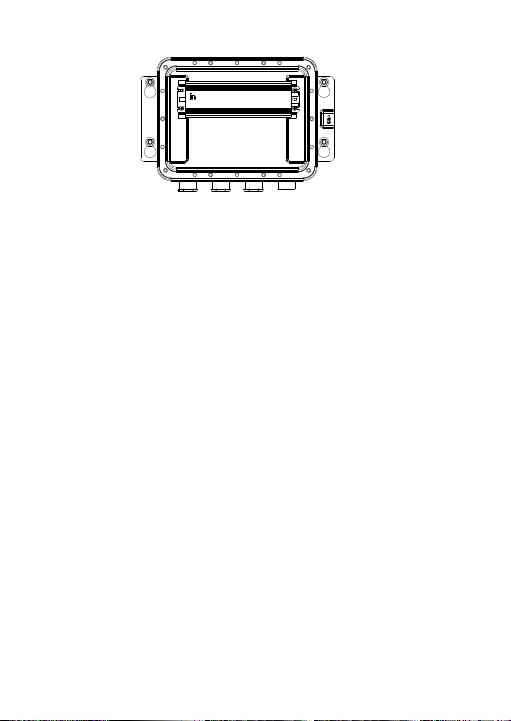
3. Route the camera cable harness through the cabl e
access hole on the junction box and tighten the
waterproof nut.
Note: Insert the PoE cable or BNC cable first, followed by
the RS-485 wires, audio input and out put wires, alarm
input a nd outp ut wires, and power supply wires. For the
power supply wires, the red plastic interface must first be
removed.
4. If the other three cable access holes are used, unscrew
the hex bolt and remove the pre-installed black solid
sealing plug.
5. Choose the applicable sealing plug from the white, blue,
and black sealing plugs according to the diameter of the
cable.
6. Route the cable through the sealing plug (1), flat washer
(2) and the hex bolt (3) and tighten to maintain IP67
rating.
14 Installation Guide
Page 15
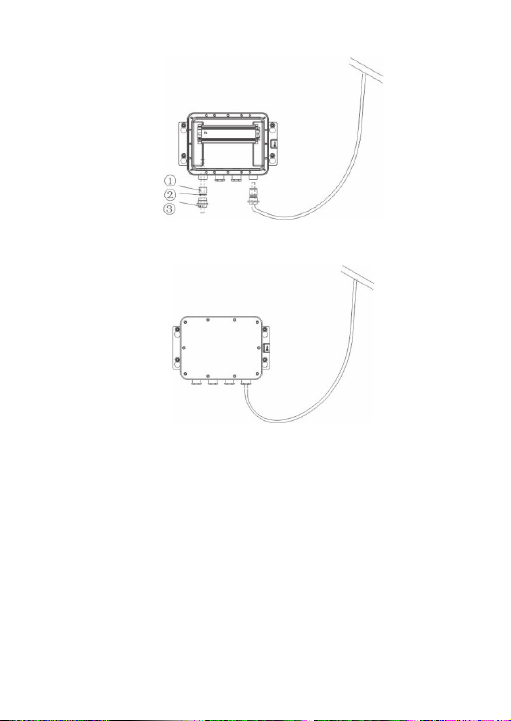
7. Connect the wires inside the junction box and attach the
cover of the junction box with the screw As.
Using the camera with an Interlogix NVR or Hybrid DVR or another system
Please refer to the NVR/DVR user manuals for instructions on
connecting and operating the camera with these systems.
Installation Guide 15
Page 16

Using the camera with TruVision Navigator
The camera can be connected to an Interlogix NVR, hybrid
DVR, or directly to TruVision Navigator. Please refer to the
user manual of TruVision Navigator and/or of the NVR or
hybrid DVR for instructions.
Access the camera over the internet
Use the web browser to access and control the camera over
the internet.
Note: Any changes made to the camera’s configuration only
apply to this camera. Only authorized users should be able to
modify camera settings.
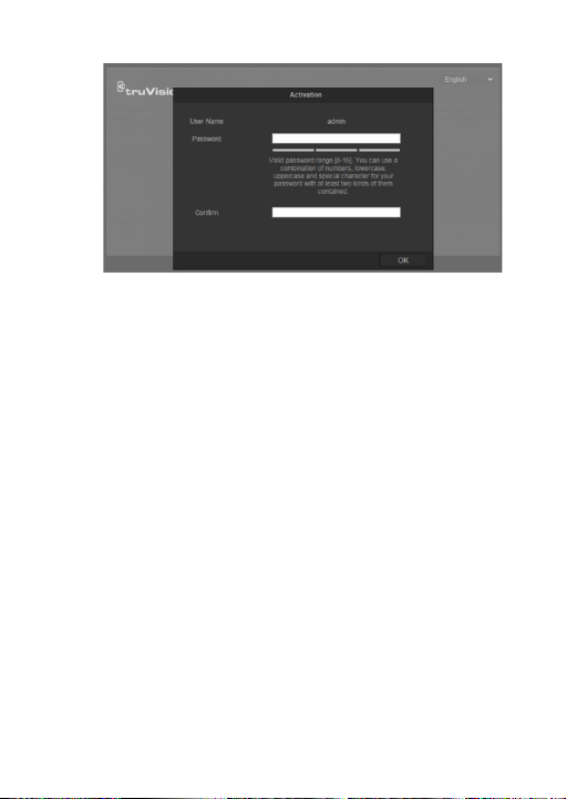
When you first start up the camera, the Activation window
appears. You must define a high-security admin password
before accessing the camera. There is no default password
provided.
You can activate a password via a web browser and via
TruVision Device Manager (included on the CD to find the IP
address of the camera).
To activate the camera via the web browser:
1. Power on the camera and connect the camera to the
network.
2. Type the IP address into the address bar of the web
browser and press Enter to enter the activation interface.
16 Installation Guide
Page 17
Note:
• The default IP address of the camera is
192.168.1.70.
• For the camera to enable DHCP by default, you
must activate the camera via TruVision Device
Manager. Please refer to the following section, “To
activate the camera via TruVision Device Manager.”
3. Type the password in the Password field.
Note: A valid password range must be between 8 and 16
characters. You can use a combination of numbers, lower
and upper case letters, and special characters : _ - , . * &
@ / $ ? Space. The password must contain characters
from at least two of these groups. We also recommend
that you reset your password regularly. For high security
systems, it is particularly recommended to reset the
password monthly or weekly for better protection.
4. Confirm the password.
5. Click OK to save the password and enter the live view
interface.
Installation Guide 17
Page 18
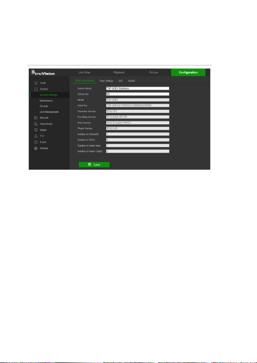
6. Click the Configuration tab on the top of the screen and
select the parameter to change.
Figure 3: Example of a configuration window
To activate the camera via TruVision Device Manager:
For instructions on how to activate the camera using TruVision
Device Manager, refer to the TruVision Device Manager User
Manual. Go to www.interlogix.com/video/product/truvision-
device-manager and click Downloads.
18 Installation Guide
Page 19

Specifications
Electrical
Voltage input
Power consumption
Miscellaneous
Connectors
Operating temperature
Dimensions
Weight
Environmental rating
Dimensions
Weight
PTZ camera
24 VAC, Hi-PoE
Max. 60 W
24 VAC, Alarm In/Out, RS-485,
262 × 330 mm (10.3 × 13.0 in.)
10 kg (22 lb.)
PTZ camera junction box
364 × 256 × 111.5 mm
4.8 kg (10.58 Ib.)
Ethernet RJ45 connector, Audio
in/output, CVBS (960H) Outp ut
-40 to +65°C (-40 to +149°F)
IP67, IK10
(14.33 × 10.08 × 4.39 in.)
Installation Guide 19
Page 20

Pin definitions
There are eight wires on a standard UTP/STP cable and each
wire is color-coded. The following shows the pin allocation and
color of straight and crossover cable connection:
Figure 4: Straight-through cable
1 White/Orange
2 Orange Orange 2
3 White -Green White -Green 3
4 Blue Blue 4
5 White/Blue White/Blue 5
6 Green Green 6
7 White/Brown White/Brown 7
8 Brown Brown 8
Figure 5: Cross-over cable
1 White/Orange
2 Orange Orange 2
3 White -Green White-Green 3
4 Blue Blue 4
5 White/Blue White/Bl ue 5
6 Green Green 6
7 White/Brown White/Brown 7
8 Brown Brown 8
Please make sure your connected cables have the same pin
assignment and color as above before deploying the cables in
your network.
20 Installation Guide
White/Orange 1
White/Orange 1
 Loading...