

Page 1

TruVision
HD-
TVI Series
4 PTZ Dome
Installation Guide
P/N 1073206-EN • REV B • ISS 03FEB17
Camera
Page 2
Copyright © 2017 United Technologies Corporation,
harmful interference when the equipment is operated in
radio communications. Operation of this equipment in a
Interlogix is part of UTC Climate, Controls & Security, a
unit of United Technologies Corporation. All rights
Trademarks and
Manufacturer Interlogix
Certifica tion
FCC compliance Class A: This equipment has been tested and found to
FCC conditions This device complies with Part 15 of the FCC Rules.
reserved.
Trade names used in this document may be
patents
trademarks or registered trademarks of the
manufacturers or vendors of the respective products.
2955 Red Hill Avenue, Costa Mesa, CA 92626-5923,
USA
Authorized EU manufacturing representative:
UTC Fire & Security B.V.
Kelvinstraat 7, 6003 DH Weert, The Netherlands
comply with the limits for a Class A digital device,
pursuant to part 15 of the FCC Rules. These limits are
designed to provide reasonable protection against
a commercial environment. This equipment generates,
uses, and can radiate radio frequency energy and, if
not installed and used in accordance with the
instruction manual, may cause harmful interference to
residential area is likely to cause harmful interference
in which case the user will be required to correct the
interference at his own expense.
Operation is subject to the following two conditions:
(1) This device may not cause harmful interference.
(2) This Device must accept any interference received,
including interference that may cause undesired
operation.
Page 3
ACMA compliance Notice! This is a Class A product. In a domestic
)
lead (Pb), or mercury (Hg). For proper recycling, return
European Union
directives
informatio n
environment this product may cause radio interference
in which case the user may be required to take
adequate measures.
Canada This Class A digital apparatus complies with CAN
ICES-003 (A)/NMB-3 (A ).
Cet appareil numérique de la classe A est conforme à
la norme CAN ICES-003 (A)/NMB-3 (A).
This product and - if applicable - the supplied
accessories too are marked with "CE" and comply
therefore with the applicable harmonized European
standards listed under the EMC Directive 2014/30/EU,
the RoHS Directive 2011/65/EU.
2012/19/EU (WEEE directive): Products marked with
this symbol cannot be disposed of as unsorted
municipal waste in the European Union. For proper
recycling, return this product to your local supplier
upon the purchase of equivalent new equipment, or
dispose of it at designated collection points. For more
information see: www.recyclethis.info.
2013/56/EU & 2006/66/EC (battery directive
product contains a battery that cannot be disposed of
as unsorted municipal waste in the European Union.
See the product documentation for specific battery
information. The battery is marked with this symbol,
which may include lettering to indicate cadmium (Cd),
the battery to your supplier or to a designated
collection point. For more information see:
www.recyclethis.info.
For contact information, see www.interlogix.com or
Contact
www.utcfssecurityproducts.eu.
: This
Page 4

Page 5

Content
Introduction 2
Product overview 2
Installation 3
Installation environment 3
Package contents 4
Cable requirements 10
DIP switch settings 10
Camera description 31
IR illuminators 33
Mounting the outdoor HD-TVI PTZ dome 34
Using the camera with a TruVision recorder or another
system 46
Specifications 47
TruVision Pendant/Wall HD-TVI PTZ camera 47
TruVision Surface/Flush HD-TVI PTZ Dome 47
TruVision Pendant/Wall IR HD-TVI PTZ Dome 48
Installation Guide 1
Page 6

Introduction
Product overview
This is the installation guide for TruVision HD-TVI Series 4
PTZ Dome Camera models:
HD-TVI 1080P PTZ Dome Cameras
TVP-2401 (30X, Pendant/Wall mount, PAL)
TVP-2402 (30X, Surface/Flush mount, PAL)
TVP-4401 (30X, Pendant/Wall mount, NTSC)
TVP-4402 (30X, Surface/Flush mount, NTSC)
HD-TVI 1080P IR PTZ Dome Cameras
TVP-2403 (30X, Pendant/Wall mount, PAL)
TVP-4403 (30X, Penda nt/W all mount, NTSC)
2 Installation Guide
Page 7

Installation
This section provides information on how to install the
cameras.
Installation environment
When installing your product, consider these factors:
• Electrical: Install electrical wiring carefully. It should be
done by qualified service personnel. Always use a CE
certified power supply (24VAC) to power the camera. Do
not overload the power cord or adapter.
• Ventilation: Ensure that the location planned for the
installation of the camera is well ventilated.
• Temperature: Do not operate the camera beyond the
specified temperature, humidity or power source ratings.
Humidity is below 90%. For the outdoor cameras that
feature built-in heaters, the operating temperature range
is -30 to 65°C (-22 to149°F)
• Moisture: Do not expose the camera to rain or moisture
or try to operate it in wet areas. Turn the power off
immediately if the camera is wet and ask a qualified
service person for servicing. Moisture can damage the
camera and also create the danger of electri c shock.
• Servicing: Do not attempt to service this camera
yourself. Any attempt to dismantle or remove the covers
from this product will invalidate the warranty and may
also result in serious injury. Refer all servicing to qualified
service personnel.
• Cleaning: Do not touch the sensor modules with fingers.
If cleaning is necessary, use a clean cloth with some
ethanol and wipe the camera gently. If the camera will not
Installation Guide 3
Page 8
be used for an extended period of time, put on the lens
cap to protect the sensors from dirt.
Package contents
Check the package and contents for visible damage. If any
components are damaged or missing, do not attempt to use
the unit; contact the supplier immediately. If the unit is
returned, it must be shipped back in its original packaging.
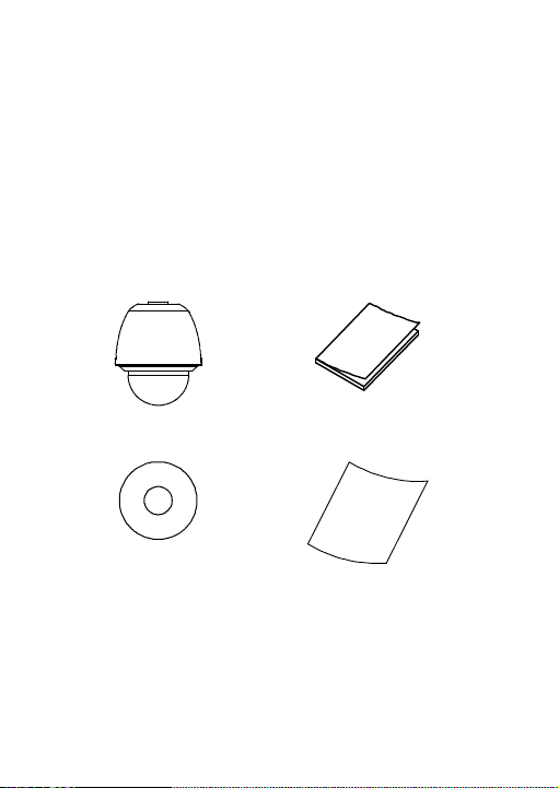
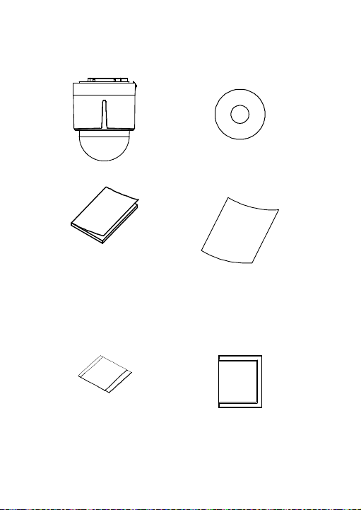
Pendant/Wall HD-TVI PTZ dome
• Camera
• CD with Configuration
manual
• Installation manual
• WEEE and Battery
Disposal sheets
4 Installation Guide
Page 9
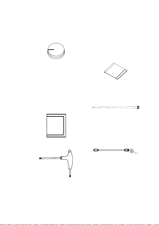
• Foam pad
(Place it at the top of the
housing where the
harness exits).
• Desiccant 1
(Two small bags. Used
as the spare desiccant
for the PTZ dome. To
use this desiccant,
place it inside the cup
base and tie it with the
zip tie below.)
• Desiccant 2
(One large bag
containing lime. Used to
keep the two bags of
desiccant away from
moisture prior to use).
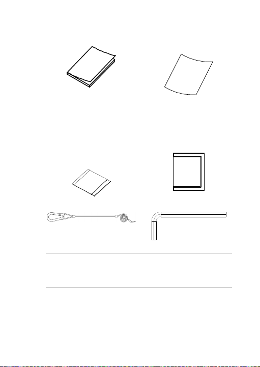
• Zip tie (X2)
(Used to tie the
desiccant 1 bags
inside the PTZ dome)
• Wrench (T20)
• Safety lanyard
Installation Guide 5
Page 10
Surface/Flush HD-TVI PTZ dome
• Camera
• CD with Configuration
manual
• Installation manual
• Desiccant 1
(Two small bags. Used as
the spare desiccant for the
PTZ dome. To use this
desiccant, place it inside
the cup base and tie it with
the zip tie below.)
6 Installation Guide
• WEEE and Battery
Disposal sheets
• Desiccant 2
(One large bag
containing lime. Used
to keep the two bags
of desiccant away
from moisture prior to
use).
Page 11
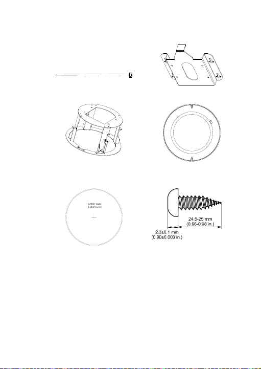
• Zip tie (2 pcs)
(Used to tie the desiccant
1 bags inside the PTZ
dome)
• housing ring
• Metal mounting base
• Trim ring
• Drill template (224 mm or
8.82 in.)
Installation Guide 7
• Phillips screws (4
pcs)
Page 12
• Dry wall anchors (4 pcs)
• Fixation pin (4 pcs)
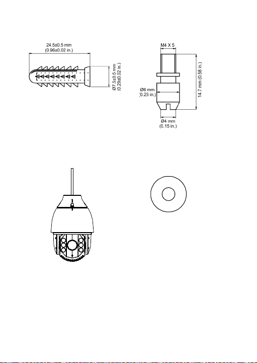
Pendant/Wall IR HD-TVI PTZ dome
• Camera
• CD with Configuration
manual
8 Installation Guide
Page 13
• Installation manual
• WEEE and Battery
Disposal sheets
• Desiccant 1
(Two small bags. Used
as the spare desiccant
for the PTZ dome. To
use this desiccant, place
it inside the cup base
and tie it with the zip tie
below.)
• Desiccant 2
(One large bag
containing lime. Used
to keep the two bags of
desiccant away from
moisture prior to use).
• Safety lanyard
• Wrench (M4)
CAUTION: Use direct plug-in UL listed power supplies
marked Class 2/CE certified or LPS (limited power source) of
the required output rating as listed on the unit.
Installation Guide 9
Page 14

CAUTION: Risk of explosion if the battery is replaced by an
incorrect type. Dispose of used batteries according to the
instructions.
Cable requirements
Choose the video cable according to the transmission
distance. The minimum requirements for the coaxial video
cable are:
75Ω impedance
100% copper core conducting wire
95% weaving copper shield
RS-485 communication cable
24 VAC power cable
DIP switch settings
HD-TVI PTZ dome
For pendant/wall PTZ dome cameras, access the DIP switch
by removing the rubber plugs on the two sides of the PTZ
housing and unscrewing the two screws insi de. Then open the
bubble assembly, remove all three foam inserts and the plastic
protective lens cover.
For surface/flush PTZ dome cameras, access the DIP
switches by rotating the housing.
Use the DIP switch to set the address and baud rate for the
PTZ dome. Value ON=1 and OFF=0.
Use the SW1 switches from the first to the eighth positions to
set the address. Use the SW2 switches to set the baud rate.
10 Installation Guide
Page 15
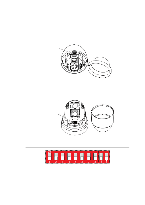
Note: The default dome address is 0. The default baud rate i s
2400.
Figure 1: DIP switch location for pendant/wall mount PTZ
dome
DIP switch
Figure 2: DIP switch location for surface/flush mount PTZ
dome
DIP switch
Figure 3: Enlarged view of the DIP switch
Installation Guide 11
Page 16

Address settings
Use the SW1 switches from 1 to 4 to set the PTZ dome
address. Refer to Table 1 on setting the PTZ dome address to
a specific number.
Table 1: Set the dome address between 0 and 15
Dome
address
0 OFF OFF OFF OFF
1 ON OFF OFF OFF
2 OFF ON OFF OFF
3 ON ON OFF OFF
4 OFF OFF ON OFF
5 ON OFF ON OFF
6 OFF ON ON OFF
7 ON ON ON OFF
8 OFF OFF OFF ON
9 ON OFF OFF ON
10 OFF ON OFF ON
11 ON ON OFF ON
12 OFF OFF ON ON
13 ON OFF ON ON
14 OFF ON ON ON
Switch no.
1 2 3 4
12 Installation Guide
Page 17

Dome
address
Switch no.
1 2 3 4
15 ON ON ON ON
Protocol settings
Use SW1 switches 5, 6 and 7 to set t he PTZ dome protocol.
Refer to Table 2 below:
Table 2: Set the dome protocol
SW1 switch no.
Protocol
5 6 7
UTC RS-485 OFF OFF OFF
PROTOCOL_PELCO_P ON OFF OFF
PROTOCOL_PELCO_D OFF ON OFF
PROTOCOL_DIGIPLEX ON ON OFF
PROTOCOL_RS422_ASCII OFF OFF ON
PROTOCOL_BOSCH_CODE OFF ON ON
PROTOCOL_AD_CODE ON ON ON
HD-TVI mode settings
Use SW1 switch number 8 to set the HD- TVI mode of the PTZ
dome. HD-TVI Mode 1.0 and HD-TVI Mode 2.0 are two
standards to transfer HD-TVI signals. HD-TVI Mode 1.0
supports a short transmission distance with a wide bandwidth
while HD-TVI Mode 2.0 supports a long transmission distance
with a narrow bandwidth. Refer to the Table 3 below:
Installation Guide 13
Page 18

Table 3: Set the HD-TVI mode
SW1 switch no.
HD-TVI mode
8
TVI 2.0 OFF
TVI 1.0 ON
Baud rate settings
Use the SW2 switches 1 and 2 to set the baud rate of the PTZ
dome. The baud rate can be 2400 bps, 4800 bps, 9600 b ps or
19200 bps. The baud rate will be set as 2400 bps by default if
it is out of this range. Refer to Table 4 below:
Table 4: Set the baud rate of the dome
SW2 switch no.
Baud rate
6 7
2400 OFF OFF
4800 ON OFF
9600 OFF ON
19200 ON ON
IR pendant/wall mount HD-TVI PTZ dome
Use the two DIP switches SW1 and SW2 to set the PTZ dome
address, baud rate, protocol, etc. Value ON =1 and OFF =0.
The switch label is on the back of the SWITCH cover, as
shown below.
14 Installation Guide
Page 19

Each number of the switch represents a DIP value, ranging
from 1 to 8 from the lowest to highest.
Figure 4: Label of DIP switch for pendant/wall mount HDTVI IR PTZ dome
Figure 5: Enlarged view of the DIP switches
Note: The default dome address is 0. The default baud rate is
2400. The default value of the 120Ω terminator is OFF.
Address settings
Use the SW1 switches to set the address of the PTZ dome.
Refer to Table 5 below :
Table 5: Set the dome address
Dome
address
1 2 3 4 5 6 7 8
0 OFF OFF OFF OFF OFF OFF OFF OFF
Switch no.
Installation Guide 15
Page 20

Dome
address
1 2 3 4 5 6 7 8
1 ON OFF OFF OFF O FF OFF OFF OFF
2 OFF ON OFF OFF OFF OFF OFF OFF
3 ON ON OFF OFF OFF OFF OFF OFF
4 OFF OFF ON OFF OFF OFF OFF OFF
5 ON OFF ON OFF OFF OFF OFF OFF
6 OFF ON ON OFF OFF OFF OFF OFF
7 ON ON ON OFF OFF OFF OFF OFF
8 OFF OFF OFF ON OFF OFF OFF OFF
9 ON OFF OFF ON OFF OFF OFF OFF
10 OFF ON OFF ON OFF OFF OFF OFF
11 ON ON OFF ON OFF OFF OFF OFF
12 OFF OFF ON ON OFF OFF OFF OFF
13 ON OFF ON ON OFF OFF OFF OFF
14 OFF ON ON ON OFF OFF OFF OFF
15 ON ON ON ON OFF OFF OFF OFF
16 OFF OFF OFF OFF ON OFF OFF OFF
17 ON OFF OFF OFF ON OFF OFF OFF
18 OFF ON OFF OFF ON OFF OFF OFF
19 ON ON OFF OFF ON OFF OFF OFF
20 OFF OFF ON OFF ON OFF OFF OFF
21 ON OFF ON OFF ON OFF OFF OFF
Switch no.
16 Installation Guide
Page 21

Dome
address
1 2 3 4 5 6 7 8
22 OFF ON ON OFF ON OFF OFF OFF
23 ON ON ON OFF ON OFF OFF OFF
24 OFF OFF OFF ON ON OFF OFF OFF
25 ON OFF OFF ON ON OFF OFF OFF
26 OFF ON OFF ON ON O FF OFF OFF
27 ON ON OFF ON ON OFF OFF OFF
28 OFF OFF ON ON ON OFF OFF O FF
29 ON OFF ON ON ON OFF OFF OFF
30 OFF ON ON ON ON OFF OFF OFF
31 ON ON ON ON ON OFF OFF O FF
32 OFF OFF OFF OFF OFF ON OFF OFF
33 ON OFF OFF OFF OFF ON OFF OFF
34 OFF ON OFF OFF OFF ON OFF OFF
35 ON ON OFF OFF OFF ON OFF OFF
36 OFF OFF ON OFF OFF ON OFF OFF
37 ON OFF ON OFF O FF ON OFF OFF
38 OFF ON ON OFF OFF ON OFF OFF
39 ON ON ON OFF OFF ON OFF OFF
40 OFF OFF OFF ON OFF ON O FF OFF
41 ON OFF OFF ON OFF ON OFF OFF
42 OFF ON OFF ON OFF ON OFF OFF
Switch no.
Installation Guide 17
Page 22

Dome
address
1 2 3 4 5 6 7 8
43 ON ON OFF ON OFF ON OFF OFF
44 OFF OFF ON ON OFF ON OFF OFF
45 ON OFF ON ON OFF ON OFF OFF
46 OFF ON ON ON OFF ON OFF OFF
47 ON ON ON ON OFF ON OFF OFF
48 OFF OFF OFF OFF ON ON OFF OFF
49 ON OFF OFF OFF ON ON OFF OFF
50 OFF ON OFF OFF ON ON OFF OFF
51 ON ON OFF OFF ON ON OFF OFF
52 OFF OFF ON OFF ON ON OFF OFF
53 ON OFF ON OFF ON ON OFF OFF
54 OFF ON ON OFF ON ON OFF OFF
55 ON ON ON OFF ON ON OFF OFF
56 OFF OFF OFF ON ON ON OFF OFF
57 ON OFF OFF ON ON ON OFF O FF
58 OFF ON OFF ON ON ON OFF OFF
59 ON ON OFF ON ON ON OFF OFF
60 OFF OFF ON ON ON ON OFF OFF
61 ON OFF ON ON ON ON OFF OFF
62 OFF ON ON ON ON ON OFF OFF
63 ON ON ON ON ON ON OFF OFF
Switch no.
18 Installation Guide
Page 23

Dome
address
1 2 3 4 5 6 7 8
64 OFF OFF OFF OFF OFF OFF ON O FF
65 ON OFF OFF OFF OFF OFF ON OFF
66 OFF ON OFF OFF OFF OFF ON OFF
67 ON ON OFF OFF OFF OFF ON OFF
68 OFF OFF ON OFF OFF OFF ON OFF
69 ON OFF ON OFF O FF OFF ON OFF
70 OFF ON ON OFF OFF OFF ON OFF
71 ON ON ON OFF OFF OFF ON OFF
72 OFF OFF OFF ON OFF OFF ON OFF
73 ON OFF OFF ON OFF OFF ON OFF
74 OFF ON OFF ON OFF OFF ON OFF
75 ON ON OFF ON OFF OFF ON OFF
76 OFF OFF ON ON OFF OFF ON OFF
77 ON OFF ON ON OFF OFF ON OFF
78 OFF ON ON ON OFF OFF ON OFF
79 ON ON ON ON OFF OFF ON OFF
80 OFF OFF OFF OFF ON OFF ON OFF
81 ON OFF OFF OFF ON OFF ON OFF
82 OFF ON OFF OFF ON OFF ON OFF
83 ON ON OFF OFF ON OFF ON OFF
84 OFF OFF ON OFF ON OFF ON OFF
Switch no.
Installation Guide 19
Page 24

Dome
address
100 OFF OFF ON OFF O FF ON ON OFF
101 ON OFF ON OFF OFF ON ON OFF
102 OFF ON ON OFF OFF ON ON OFF
103 ON ON ON OFF O FF ON ON OFF
104 OFF OFF OFF ON OFF ON ON OFF
105 ON OFF OFF ON OFF ON ON OFF
1 2 3 4 5 6 7 8
85 ON OFF ON OFF ON O FF ON OFF
86 OFF ON ON OFF O N OFF ON OFF
87 ON ON ON OFF ON OFF ON OFF
88 OFF OFF OFF ON ON OFF ON OFF
89 ON OFF OFF ON ON OFF ON OFF
90 OFF ON OFF ON ON OFF ON OFF
91 ON ON OFF ON ON OFF ON O FF
92 OFF OFF ON ON ON OFF ON OFF
93 ON OFF ON ON ON OFF ON OFF
94 OFF ON ON ON ON OFF ON OFF
95 ON ON ON ON ON OFF ON OFF
96 OFF OFF OFF OFF OFF ON ON OFF
97 ON OFF OFF OFF OFF ON ON OFF
98 OFF ON OFF OFF OFF ON ON OFF
99 ON ON OFF OFF OFF ON ON OFF
Switch no.
20 Installation Guide
Page 25

Dome
address
1 2 3 4 5 6 7 8
106 OFF ON OFF ON OFF ON ON OFF
107 ON ON OFF ON OFF ON ON OFF
108 OFF OFF ON ON OFF ON ON OFF
109 ON OFF ON ON OFF ON ON OFF
110 OFF ON ON ON OFF ON ON OFF
111 ON ON ON ON OFF ON ON OFF
112 OFF OFF OFF OFF ON ON ON OFF
113 ON OFF OFF OFF ON ON ON OFF
114 OFF ON OFF OFF ON ON ON OFF
115 ON ON OFF OFF ON ON ON OFF
116 OFF OFF ON OFF ON ON ON OFF
117 ON OFF ON OFF ON ON ON OFF
118 OFF ON ON OFF ON ON ON OFF
119 ON ON ON OFF ON ON ON OFF
120 OFF OFF OFF ON ON ON ON OFF
121 ON OFF OFF ON ON ON ON OFF
122 OFF ON OFF ON ON ON ON OFF
123 ON ON OFF ON ON ON ON OFF
124 OFF OFF ON ON ON ON ON OFF
125 ON OFF ON ON ON ON ON OFF
126 OFF ON ON ON ON ON ON OFF
Switch no.
Installation Guide 21
Page 26

Dome
address
127 ON ON ON ON ON ON ON OFF
128 OFF OFF OFF OFF OFF OFF OFF ON
129 ON OFF OFF OFF O FF OFF OFF ON
130 OFF ON OFF OFF OFF OFF OFF ON
131 ON ON OFF OFF OFF OFF OFF ON
132 OFF OFF ON OFF O FF OFF OFF ON
133 ON OFF ON OFF OFF OFF OFF ON
134 OFF ON ON OFF OFF OFF OFF ON
135 ON ON ON OFF O FF OFF OFF ON
136 OFF OFF OFF ON OFF OFF OFF ON
137 ON OFF OFF ON OFF OFF OFF ON
138 OFF ON OFF ON OFF OFF OFF ON
139 ON ON OFF ON OFF OFF OFF ON
140 OFF OFF ON ON OFF OFF OFF ON
141 ON OFF ON ON OFF OFF OFF ON
142 OFF ON ON ON OFF OFF OFF ON
143 ON ON ON ON OFF OFF OFF ON
144 OFF OFF OFF OFF ON OFF OFF ON
145 ON OFF OFF OFF ON OFF OFF ON
146 OFF ON OFF OFF ON OFF OFF ON
147 ON ON OFF OFF ON OFF OFF ON
1 2 3 4 5 6 7 8
Switch no.
22 Installation Guide
Page 27

Dome
address
1 2 3 4 5 6 7 8
148 OFF OFF ON OFF ON OFF OFF ON
149 ON OFF ON OFF ON OFF OFF ON
150 OFF ON ON OFF ON OFF OFF ON
151 ON ON ON OFF ON OFF OFF ON
152 OFF OFF OFF ON ON OFF O FF ON
153 ON OFF OFF ON ON OFF OFF ON
154 OFF ON OFF ON ON OFF OFF ON
155 ON ON OFF ON ON OFF OFF ON
156 OFF OFF ON ON ON OFF OFF ON
157 ON OFF ON ON ON OFF OFF ON
158 OFF ON ON ON ON OFF OFF ON
159 ON ON ON ON ON OFF OFF ON
160 OFF OFF OFF OFF OFF ON O FF ON
161 ON OFF OFF OFF OFF ON OFF ON
162 OFF ON OFF OFF OFF ON OFF ON
163 ON ON OFF OFF OFF ON OFF ON
164 OFF OFF ON OFF OFF ON OFF ON
165 ON OFF ON OFF OFF ON O FF ON
166 OFF ON ON OFF OFF ON OFF ON
167 ON ON ON OFF OFF ON OFF ON
168 OFF OFF OFF ON OFF ON O FF ON
Switch no.
Installation Guide 23
Page 28

Dome
address
169 ON OFF OFF ON OFF ON OFF ON
170 OFF ON OFF ON OFF ON OFF ON
171 ON ON OFF ON OFF ON OFF ON
172 OFF OFF ON ON OFF ON OFF ON
173 ON OFF ON ON OFF ON OFF ON
174 OFF ON ON ON OFF ON OFF ON
175 ON ON ON ON OFF ON OFF ON
176 OFF OFF OFF OFF ON ON OFF ON
177 ON OFF OFF OFF ON ON OFF ON
178 OFF ON OFF OFF ON ON OFF ON
179 ON ON OFF OFF ON ON OFF ON
180 OFF OFF ON OFF ON ON OFF ON
181 ON OFF ON OFF ON ON OFF ON
182 OFF ON ON OFF ON ON OFF ON
183 ON ON ON OFF ON ON OFF ON
184 OFF OFF OFF ON ON ON OFF ON
185 ON OFF OFF ON ON ON OFF ON
186 OFF ON OFF ON ON ON OFF ON
187 ON ON OFF ON ON ON OFF ON
188 OFF OFF ON ON ON ON OFF ON
189 ON OFF ON ON ON ON OFF ON
1 2 3 4 5 6 7 8
Switch no.
24 Installation Guide
Page 29

Dome
address
1 2 3 4 5 6 7 8
190 OFF ON ON ON ON ON OFF ON
191 ON ON ON ON ON ON OFF ON
192 OFF OFF OFF OFF OFF OFF ON ON
193 ON OFF OFF OFF OFF OFF ON ON
194 OFF ON OFF OFF OFF OFF ON ON
195 ON ON OFF OFF OFF OFF ON ON
196 OFF OFF ON OFF OFF OFF ON ON
197 ON OFF ON OFF OFF OFF ON ON
198 OFF ON ON OFF OFF OFF ON ON
199 ON ON ON OFF OFF OFF ON ON
200 OFF OFF OFF ON OFF OFF ON ON
201 ON OFF OFF ON OFF OFF ON ON
202 OFF ON OFF ON OFF OFF ON ON
203 ON ON OFF ON OFF OFF ON ON
204 OFF OFF ON ON OFF OFF ON ON
205 ON OFF ON ON OFF O FF ON ON
206 OFF ON ON ON OFF OFF ON ON
207 ON ON ON ON OFF OFF ON ON
208 OFF OFF OFF OFF ON OFF ON ON
209 ON OFF OFF OFF ON OFF ON ON
210 OFF ON OFF OFF ON OFF ON ON
Switch no.
Installation Guide 25
Page 30

Dome
address
211 ON ON OFF OFF ON OFF ON ON
212 OFF OFF ON OFF ON OFF ON ON
213 ON OFF ON OFF ON OFF ON ON
214 OFF ON ON OFF ON OFF ON ON
215 ON ON ON OFF ON OFF ON ON
216 OFF OFF OFF ON ON OFF ON ON
217 ON OFF OFF ON ON OFF ON ON
218 OFF ON OFF ON ON OFF ON ON
219 ON ON OFF ON ON OFF ON ON
220 OFF OFF ON ON ON OFF ON ON
221 ON OFF ON ON ON OFF ON ON
222 OFF ON ON ON ON OFF ON ON
223 ON ON ON ON ON OFF ON ON
224 OFF OFF OFF OFF OFF ON ON ON
225 ON OFF OFF OFF O FF ON ON ON
226 OFF ON OFF OFF OFF ON ON ON
227 ON ON OFF OFF OFF ON ON ON
228 OFF OFF ON OFF O FF ON ON ON
229 ON OFF ON OFF OFF ON ON ON
230 OFF ON ON OFF OFF ON ON ON
231 ON ON ON OFF O FF ON ON ON
1 2 3 4 5 6 7 8
Switch no.
26 Installation Guide
Page 31

Dome
address
1 2 3 4 5 6 7 8
232 OFF OFF OFF ON OFF ON ON ON
233 ON OFF OFF ON OFF ON ON ON
234 OFF ON OFF ON OFF ON ON ON
235 ON ON OFF ON OFF ON ON ON
236 OFF OFF ON ON OFF ON ON ON
237 ON OFF ON ON OFF ON ON ON
238 OFF ON ON ON OFF ON ON ON
239 ON ON ON ON OFF ON ON ON
240 OFF OFF OFF OFF ON ON ON ON
241 ON OFF OFF OFF ON ON ON ON
242 OFF ON OFF OFF ON ON ON ON
243 ON ON OFF OFF ON ON ON ON
244 OFF OFF ON OFF ON ON ON ON
245 ON OFF ON OFF ON ON ON ON
246 OFF ON ON OFF ON ON ON ON
247 ON ON ON OFF ON ON ON ON
248 OFF OFF OFF ON ON ON ON ON
249 ON OFF OFF ON ON ON ON ON
250 OFF ON OFF ON ON ON ON ON
251 ON ON OFF ON ON ON ON ON
252 OFF OFF ON ON ON ON ON ON
Switch no.
Installation Guide 27
Page 32

Dome
address
253 ON OFF ON ON ON ON ON ON
254 OFF ON ON ON ON ON ON ON
255 ON ON ON ON ON ON ON ON
Baud rate settings
Use the SW2 switch numbers 1 a nd 2 to set the baud rate of
the PTZ dome. The baud rate can be 2400 bps, 4800 bps,
1 2 3 4 5 6 7 8
Switch no.
9600 bps or 19200 bps. The baud rate will be set as 2400 bps
by default if it is out of this range. Refer to Table 6 below:
Table 6: Set the baud rate of the dome
SW2 switch no.
Baud rate
1 2
2400 OFF OFF
4800 ON OFF
9600 OFF ON
19200 ON ON
28 Installation Guide
Page 33

Protocol settings
Use SW2 switches numbers 3, 4 a nd 5 to set the PTZ dome
protocol. Refer to Table 2 below:
Table 7: Set the dome protocol
SW2 switch no.
Protocol
3 4 5
UTC RS-485 OFF OFF OFF
PROTOCOL_PELCO_P ON OFF OFF
PROTOCOL_PELCO_D OFF ON OFF
PROTOCOL_DIGIPLEX ON ON OFF
PROTOCOL_RS422_ASCII OFF OFF ON
PROTOCOL_BOSCH_CODE OFF ON ON
PROTOCOL_AD_CODE ON ON ON
HD-TVI Mode Settings
Use SW2 switch number 7 to set the HD-TVI mode of the PTZ
dome. HD-TVI Mode 1.0 and HD-TVI Mode 2.0 are two
standards to transfer HD-TVI signals. For HD-TVI Mode 1.0, it
supports short transmission distance with wide bandwidth
while for HD-TVI Mode 2.0, it supports long transmission
distance with narrow bandwidth. Refer to Tabl e 8 below:
Installation Guide 29
Page 34

Table 8: Set the HD-TVI Mode
SW2 switch no.
HD-TVI mode
7
V2.0 OFF
V1.0 ON
Terminal resistor settings
Use SW2 switch number 8 to turn on/off the 120Ω terminal
resistor. When multiple PTZ domes are controlled through one
RS-485 bus in serial mode, there must be a terminal resistor
at the end of the RS-485 bus according to the RS-485 protocol
standard. To ensure that the whole serial system operates
normally, the PTZ dome at the end of the RS-485 bus needs
to enable the terminal resistor.
Table 9: Set the terminal resistor
Terminal matching
resistance
SW2 switch no.
8
Turn on the resistor ON
Turn off the resistor OFF
Note: The O-ring in the groove of the switch cover is
waterproof.
30 Installation Guide
Page 35

Camera description
7. Bubble
Figure 6: Outdoor HD-TVI PTZ do me
1. HD-TVI output (Whi te)
2. Power supply
a. Black 24 VAC
b. Yellow/Green GND
c. Red 24 VAC
3. RS-485 port
a. Orange RS-485+
b. Yellow RS-485-
Installation Guide 31
4. 960H analog outp ut
(Black)
5. 2 Alarm inputs
(YELLOW/BLUE-
ALARM_IN1,
YELLOW/ORANGEALARM_IN2)/ 1 Alarm
output (WHITE/REDALARM_OUT1)
6. Housi ng
Page 36

Figure 7: Indoor HD-TVI PTZ dome
7. Bubble
1. HD-TVI output (Whi te)
2. Power supply
a. Black 24 VAC
b. Yellow/Green GND
c. Red 24 VAC
3. RS-485 port
a. Orange RS-485+
b. Yellow RS-485-
4. 960H analog outp ut
5. 2 Alarm inputs
6. Housi ng
(Black)
(YELLOW/BLUE-
ALARM_IN1,
YELLOW/ORANGEALARM_IN2)/1Alarm
output (WHITE/REDALARM_OUT1)
32 Installation Guide
Page 37

Figure 8: IR outdoor HD-TVI PTZ dome
5. Housi ng
1. HD-TVI output (Whi te)
2. Power supply
a. Black 24 VAC
b. Yellow/Green GND
c. Red 24 VAC
3. RS-485 port
a. Orange RS-485+
b. Yellow RS-485-
4. 960H analog outp ut
(Black)
IR illuminators
The IR PTZ dome camera’s built-in IR illumination provides
high-quality video in low-light environment s, eve n when t here
is no other illumination available.
Installation Guide 33
Page 38

You can configure the IR illumination using the OSD menu or
a recorder such as TVN and TVR. If the function is enabled,
the IR light is ON when the camera enters night (black and
white) mode. If disabled, the IR light is always OFF.
The visible IR range may vary due to multiple factors such as
weather, IR reflection level of objects in t he frame, lens
adjustment, and camera settings. Please refer to the camera
datasheet for the standard IR range.
Note: Avoid installing the IR camera in close proximity to a
solid object, such as a tree or wall. The reflection will cause
over-exposure and loss of detail in the field of view.
Mounting the outdoor HD-TVI PTZ dome
Mount the bracket on the wall
Wall mounting is suitable for indoor/outdoor solid wall
construction. The following requirements are mandatory
preconditions for wall mounting:
The wall must be thick enough to install the expansion
screws.
Please ensure that the wall is strong enough to withstand
more than eight times the weight of the dome and bracket.
To mount the bracket:
1. Remove the rubber plugs on the two sides of the PTZ
housing.
2. Unscrew the two screws located below the rubber plugs.
3. Open the bubble assembly and remove all three foam
inserts and the plastic protective lens cover.
34 Installation Guide
Page 39

4. Set the address and baud rate for the dome according to
“DIP switch settings” on the page 10.
5. Attach the safety cable to the bracket.
6. Use the supplied template to mark out the mounting area.
Drill four screw holes in the wall according to the holes of
the bracket, and then insert M8 expansion screws (not
supplied) into the mounting holes.
7. Attach the bracket to the wall by aligning the four screw
holes of the bracket with expansion screws on the wall.
8. Secure the bracket with four hex nuts and washers.
Mount the camera on the bracket
To mount the outdoor HD-TVI PTZ dome:
1. Hang the safety cable to the dome and then hook the
dome to the bracket, as sho wn below.
Installation Guide 35
Page 40

2. Route the cables from the pendant-mount bracket.
3. Install the PTZ dome to the bracket, and secure the PTZ
dome using the screws enclosed with the bracket.
36 Installation Guide
Page 41

To mount the pendant/wall IR HD-TVI PTZ dome:
1. Set the address and baud rate for the dome according to
“DIP switch settings” on the page 10.
2. Hang the safety cable to the HD-TVI PTZ dome and then
hook the dome to the bracket, as shown below.
3. Route the cables of the PTZ dome through the bracket.
4. Connect the corresponding video/power/RS-485 cables.
5. Install the PTZ dome to the bracket, and s ecure the PTZ
dome using t he scr ews enclosed with the bracket.
Installation Guide 37
Page 42

Mount the camera by flush-mount
Flush-mo unting is suitable for indoor ceiling construction. The
following requirements are mandatory preconditions for
mounting:
The height of the space above the ceiling must be greater
than 250 mm (9.843 in).
The thickness of the ceiling must be between 5 and
40 mm (0.197 to 1.575 in).
The ceiling must be strong enough to withstand more
than fo ur times the weight of the dome and its
accessories.
To mount the surface/flush HD-TVI PTZ dome flush with a
ceiling:
1. Rotate the lower dome counterclockwise to separate it
from the back box, as shown below.
38 Installation Guide
Page 43

Back box
Protective foam Sticker
Lower dome
2. Remove the protective lens cover, foam and sticker from
the dome drive.
3. Set the address and baud rate for the HD-TVI dome.
Please refer to Section “DIP switch settings” on page 10.
4. Attach the lower dome to the back box. Rotate it
clockwise to secure it.
5. Using the drill template, drill a hole on the ceiling.
6. Connect the cables.
Make sure the video cable and control wire have been
connected to the corresponding interfaces.
Installation Guide 39
Page 44

7. Adjust the height of the two housing tabs by turni ng the
Ceiling
Lock
screw on which they are attached. The distance of the
tabs from the housing ring must be greater than the
thickness of the ceiling.
Housing tab
Screw
8. Make sure that t he housing tab is closed and then PUSH
the housing into the pass-t hroug h hole. Hold the housing
and secure it by screwing the housing tabs down to the
mounting surface.
9. Install the trim ring.
A. Attach the trim ring to the lower dome and align the
triangular notch of the trim ring with the arrow label
on the in-ceiling m ounti ng bracket.
B. After firmly placing the trim ri ng on the ceiling, rotate
the trim ring in the direction of arrow to secure the
trim ring in place.
40 Installation Guide
Page 45

Arrow label
Notch
Note:
Remove the protective film on the lower dome when the
installation is completed.
In order to obtain clear video images, wear anti-static
gloves when you install the PTZ dome.
Surface mount the camera
Use surface mounting for indoor/outdoor solid ceiling
construction. The following requirements are mandatory
preconditions for mounting:
The thickness of the ceiling must range from 5 to 40 mm
(0.197 to 1.575 in).
The ceiling must be strong enough to withstand more
than fo ur times the weight of the dome and its
accessories.
To mount the surface/flush HD-TVI PTZ dome to a ceiling:
Note: When installing the PTZ to a ceiling, do not use drywall
anchors.
1. Remove the mounting bracket.
Installation Guide 41
Page 46

A. Remove t he four screws on the back box using a
screwdriver.
B. Remove the in-ceiling mounting bracket.
C. Screw the four fixation pins onto the back box using
a screwdriver.
42 Installation Guide
Page 47

2. Wire the dome.
Route the cables of dome either from the top or the side
of the back box. For the cables routed from the top of
the back box, you must drill a cable hole in the ceiling.
3. Surface mounting:
A. Rotate the lower dome counterclockwise to separate
it from the back box.
B. Remove the protective lens cover, foam and sticker
from the dome drive.
C. Set the address and ba ud rate for the PTZ dome.
D. Attach the lower dome to the back box and rotate it
clockwise to secure it.
E. Use the mounting base as a template to mark fo ur
screw holes onto t he ceiling.
Installation Guide 43
Page 48

F. If you route cables from the top of the back box,
mark the cable hole on the ceiling and drill a hole.
G. Secure the mounting base to the ceiling with Phillips
screws.
If the PTZ dome is installed onto a wooden wall,
use the Phillips screws to secure the mounting
base.
If the dome is installed onto the cement wall, drill
four mounting holes, 5 mm in size, onto the
mounting surface according to the hole locations.
Then insert the cement screws (not included) into
the holes and tighten.
44 Installation Guide
Page 49

Cable hole
Screw holes
H. Install the HD-TVI PTZ dome on to the mounting
base.
Route the cables for the HD-TVI dome. Align the
base of the HD-TVI dome wit h the mounting base.
Align the direction of the arrow with the spring end of
the mounting base.
Push the HD-TVI dome upwards (1) and then
forwards (2) in the direction of the arrow. When the
HD-TVI dome is in position, the spring will
automatically snap into the lock clip firmly. See the
figure below:
Installation Guide 45
Page 50

Note:
Please remove the protective film on the lower dome
after the installation is finished.
Do not touch the bubble of the lower dome di rectly with
your hand. The image will be blurred.
Using the camera with a TruVision recorder or another system
Please refer to the recorder user manual for instructions on
connecting and operating the camera with these systems.
46 Installation Guide
Page 51

Specifications
Electrical
Voltage input
Power consumption
Miscellaneous
Connectors
Operating temperature
Dimensions
Weight
Environmental rating
Electrical
Voltage input
Power consumption
M
Connectors
TruVision Pendant/Wall HD-TVI PTZ camera
24 VAC
Max. 20 W
24 VAC, Alarm In/Out, HD-TVI
220 × 226 mm
3 kg (6.61 Ib.)
TruVision Surface/Flush HD-TVI PTZ Dome
24 VAC
iscellaneous
24 VAC, Alarm In/Out,
Output, 960H Analog Output
-30 to +65 °C (-22 to +149°F)
(8.66 × 10.5 in.)
IP66, IK10
Max. 20 W
HD-TVI Output, 960H Analog
Output
Installation Guide 47
Page 52

Operating temperature
-10 to +50 °C (14 to 122 °F)
Dimensions
Weight
Environmental rating
Electrical
Voltage input
Power consumption
Miscellaneous
Connectors
Operating temperature
Dimensions
Wei
Flush: 246 × 245 mm
3 kg (6.61 Ib.)
(9.69 × 9.65 in.)
Surface: 179.8 × 239 mm
(7.07 × 9.41 in.)
IP54, IK10
TruVision Pendant/Wall IR HD-TVI PTZ Dome
24 VAC
Max. 30 W
24 VAC, HD-TVI Output, 960H
220 × 353.4 mm
ght 4.5 kg (9.92 Ib.)
Analog Output
-30 to +65 °C (-22 to +149°F)
(8.66 × 13.91 in.)
48 Installation Guide
Page 53

Installation Guide 49
Page 54

Page 55

Page 56

 Loading...