

Page 1

TruVision IP PTZ
Camera FW5.1
Installation Guide
P/N 1073029-EN • REV C • ISS 29SEP15
Page 2
Copyright © 2015 United Technologies Corporation.
2006/66/EC (b attery directive): T his product contains a battery that cannot be disposed of
Contact information
For contact inf ormation, see www.i nterlogix.com or www.utcfssecuritypr oducts.eu.
Interlogix is p art of UTC Building & Industrial Systems, a unit of United T echnologies
Corporation. All rights reserved.
Trademarks an d
Manufacturer
FCC compliance
ACMA compliance
European Union
The Product N ame and logo are trad emarks of United T echnologies.
patents
Other trade names us ed in this document m ay be trademarks or reg istered trademarks of the
manufacturers or vendors of the r espective products.
Interlogix
2955 Red Hill Avenue, Costa Mesa, C A 92626-5923, USA
Authorized EU manufacturing repr esentative:
UTC Fire & Security B.V .
Kelvinstraat 7, 6003 DH Weert, Th e Netherlands
Certification
Class A: This eq uipment has been t ested and found to com ply with the limits f or a Class A
digital devic e, pursuant to part 15 of the FCC Rules. These limits are designed to provide
reasonable pr otection against har mful interference w hen the equipment is operated in a
commercial environment. This equ ipment generates, us es, and can radiat e radio frequency
energy and, if not installed and us ed in accordance wit h the instruction m anual, may cause
harmful int erference to radio com munications. Oper ation of this equipment in a residential ar ea
is likely to c ause harmful interf erence in which case t he user will be requir ed to correct the
interferenc e at his own expense.
This device complies with Part 15 of the FCC Rules. O peration is subject to the followi ng two
conditions:
(1) This device m ay not cause harmful interference
(2) This Device m ust accept any interf erence received, inc luding interferenc e that may
cause undesir ed operation.
Any changes or modifications not expressly approved b y the party responsi ble for complianc e
could void th e user’s authority t o operate the equipm ent.
Notice! This is a Class A pr oduct. In a domestic envir onment this product may cause radio
interferenc e in which case the us er may be required t o take adequate measur es.
Canada This Class A di gital apparatus c omplies with Canadian ICES-003.
Cet appareil numérique de la class e A est conforme à l a norme NMB-0330 du C anada.
12004/108/EC (EMC directive): Hereby, UTC Fire & Security d eclares that this device is in
directives
compliance wi th the essential req uirements and other r elevant provisions of Directive
2004/108/EC.
2012/19/EU (WEEE directive): Pr oducts marked with t his symbol cannot b e disposed of as
unsorted munic ipal waste in the Eur opean Union. For p roper recycling, ret urn this product to
your local su pplier upon the purch ase of equivalent new equipment, or disp ose of it at
designated c ollection points. For more information s ee: www.recyclethis.i nfo.
as unsorted municip al waste in the European U nion. See the product docume ntation for
specific battery inf ormation. The battery is mark ed with this symbol, whi ch may include
lettering to indicate cadmium (Cd), lead (Pb), or mercury (Hg). For proper r ecycling,
return the battery t o your supplier or to a desi gnated collection point. For more
information see: www.recyclethis.info.
N4131
Page 3

Content
Introduction 4
Product overview 4
Before you begin 4
Installation environment 5
Camera description 6
Connections 7
Installing a camera 9
Wall-mount camera 9
TVP-1122/3122 wall-mount camera 11
Flush-mount camera 11
Surface-mount camera 14
Using the camera with an Interlogix NVR or Hybrid DVR or
another system 18
Using the camera with TruVision Navigator 18
Accessing the camera over the internet 18
Specifications 20
Pin definitions 21
Installation Guide 3
Page 4

Introduction
This installation guide provides basic information on setting
up and using the camera. Detailed information on the
cameras can be found in the configuration manual.
Product overview
This is the installation guide for following TruVision IP PTZ
camera models:
TVP-1101 (1.3 MPX pendant, 20X, PAL)
TVP-3101 (1.3 MPX pendant, 20X, NTSC)
TVP-1102 (1.3 MPX surface, 20X, PAL)
TVP-3102 (1.3 MPX surface, 20X, NTSC)
TVP-1103 (1.3 MPX flush, 20X, PAL)
TVP-3103 (1.3 MPX flush, 20X, NTSC)
TVP-1104 (2 MPX pendant, 20X, PAL)
TVP-3104 (2 MPX pendant, 20X, NTSC)
TVP-1105 (2 MPX surface, 20X, PAL)
TVP-3105 (2 MPX surface, 20X, NTSC)
TVP-1106 (2 MPX flush, 20X, PAL)
TVP-3106 (2 MPX flush, 20X, NTSC)
TVP-1107 (2 MPX pendant, 30X, PAL)
TVP-3107 (2 MPX pendant, 30X, NTSC)
TVP-1122 (2 MPX pendant, 30X, IR, PAL)
TVP-3122 (2 MPX pendant, 30X, IR, NTSC)
Before you begin
Unpack everything. Check the items for damage, and verify
that all items are included. The camera is shipped with the
following items:
Dome camera
4 Installation Guide
Page 5

Installation Guide
CD with the Configuration Manual and Device Manager
Installation environment
When installing your camera, consider these factors:
• Place the camera in a secure location.
• Ensure that the camera is in a well-ventilated area.
• Do not expose the camera to rain or moisture.
Caution: Risk of explosion if battery is replaced by an
incorrect type. Dispose of used batteries according to the
instructions.
Installation Guide 5
Page 6
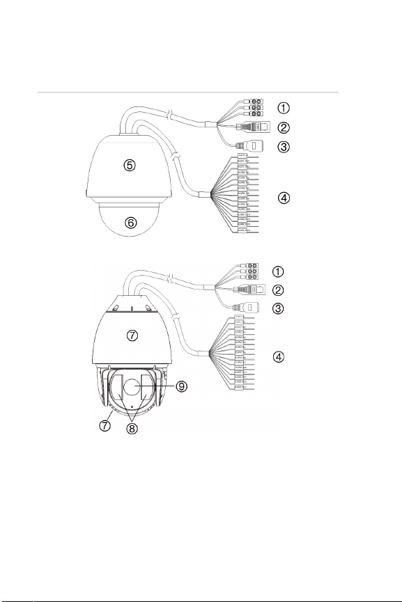
Camera description
9. Came ra
Figure 1: Overview of the dome camera (wall-mount
shown)
TVP-1122/3122 cameras only:
1. Power supply cord
Connect 24 VAC power supply
2. Video output
Connect the BNC connector to a
CCTV monitor
3. Ethernet RJ45 connector.
Connect to the network devices
Connect to the Hi-PoE switch
4. Alarm input/outputs and audio
in/out port
5. Housing
6. Bubble
7. Metal housing
8. IR LEDs
6 Installation Guide
Page 7
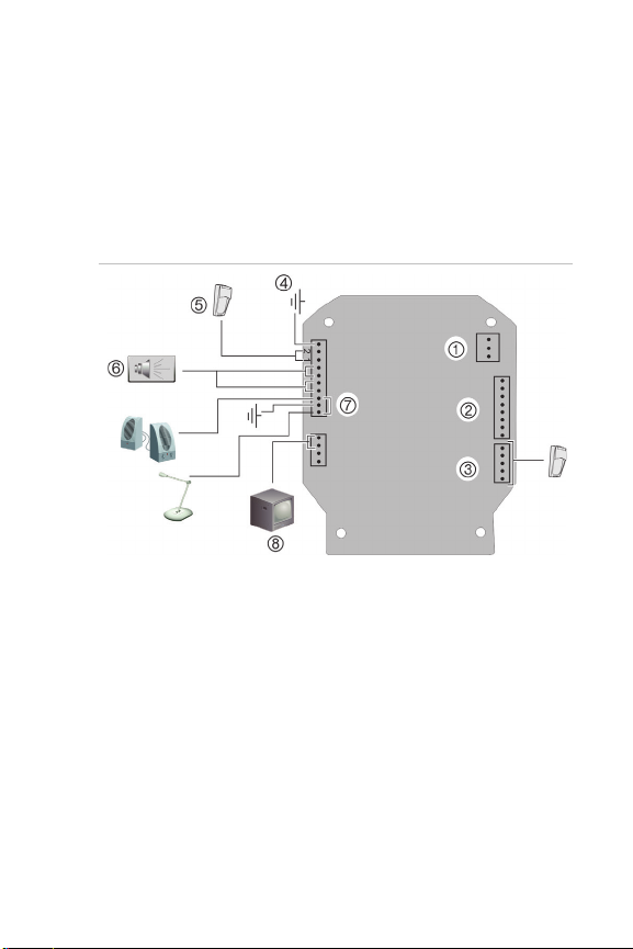
Connections
There are seven built-in alarm inputs to use as internal
alarm triggers and two alarm built-in outputs in the camera
housing. These connections do not apply to the TVP1122/3122 cameras.
Note: The DIP switches are not used.
Figure 2: Connections to the circuit board (excludes
TVP-1122/3122)
1. Power supply: Connect +24 VAC power supply and GND.
2. RJ45 connector: Connect to the network.
Caution: The RJ45 connector on the camera module is not for connecting
the network. It is an RS-232 port for troubleshooting.
3. Alarm inputs 3 to 7: Connect to up to five alarm input devices.
4. GND
5. Alarm inputs 1 and 2: Connect to up to two alarm input devices.
6. Alarm outputs 1 and 2: Connect up to two output devices
7. AIN, AOUT: Connect audio input, audio output, and GND to the audio
terminals.
8. VIDEO: Connect a CCTV monitor to the video terminals.
Alarm input and output connections
The alarm output can be used to turn on and off an external
alarm device. Connect a 30 VDC/1 A external power supply
Installation Guide 7
Page 8
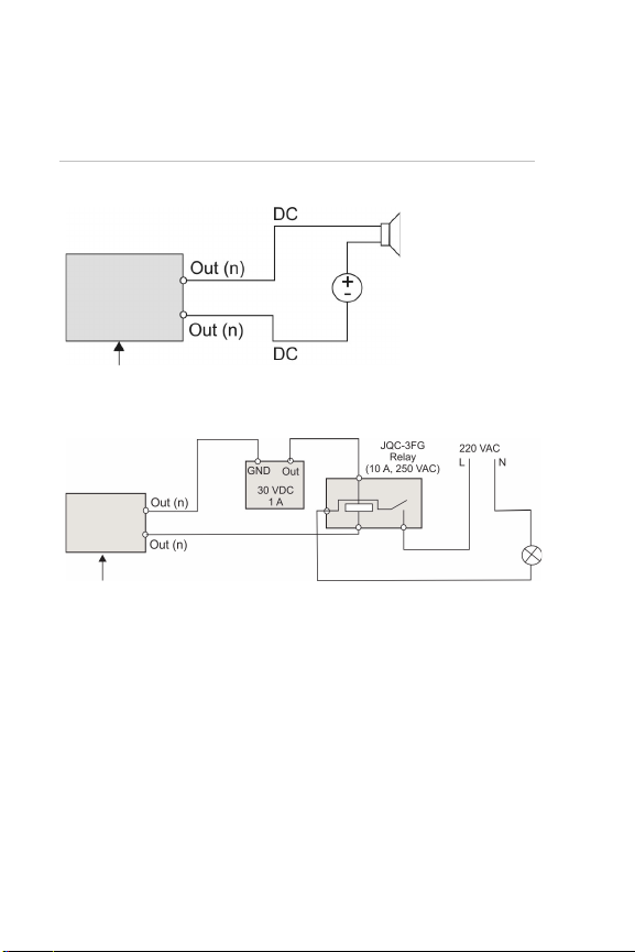
to the alarm output. If using an AC power supply, an
Dome camera
relay output
Alternating current:
Dome camera
relay output
external relay must be used to prevent electric shock and
damage to the device. See Figure 3 below.
Figure 3: External alarm output
Direct current:
8 Installation Guide
Page 9

Installing a camera
RED
AC24V
YELLOW/GREEN
BLACK
AC24V
Wall-mount camera
1. Prepare the mounting surface and install the camera
bracket.
2. Unscrew the bubble from the camera and remove the
protective tape from the PTZ module (excluding TVP-
1122).
3. Press the two tabs on either side of the PTZ module
and remove the module from the camera housing
(excluding TVP-1122).
4. Route the cables from the pendant bracket as shown
below.
Installation Guide 9
Page 10

5. Attach the safety cable to the bracket and connect the
cables to the PCB of the module through the cable entry
hole on top of the housing.
Safety cable
Note: If alarm and audio input/output relays are to be
used, also connect them to the PCB of the module.
Caution: The safety cable is made of metal. Please
ensure that it does not touch the PCB of the module.
6. Attach the camera housing to the bracket using the
screws enclosed with the bracket.
7. Insert the PTZ module into the housing:
Position the tabs on the PTZ module by aligning the
arrow label on the module with those on the housing
(see below). The module should firmly snap into
position. If using a SD card, insert it into the module
before inserting the module into the housing.
10 Installation Guide
Page 11

Caution: The RS-232 serial port on the camera is not a
Safety cable
network connection.
8. Re-attach the bubble by screwing it to the housing.
9. See “Accessing the camera over the internet” on page
18 to configure the camera over the internet. Refer to
the Configuration Manual for detailed information.
TVP-1122/3122 wall-mount camera
1. Prepare the mounting surface and install the camera
bracket.
2. Attach the safety cable to the bracket and then route the
cables from the pendant bracket as shown below.
3. See “Accessing the camera over the internet” on page
18 to configure the camera over the internet. Refer to
the Configuration Manual for detailed information.
Flush-mount camera
1. Drill a hole on the ceiling using the drill template.
Installation Guide 11
Page 12

2. Tie three safety cables (not supplied) to the safety
hooks on the camera and hang the camera from a
secure point.
3. Unscrew the bubble from the camera and remove the
protective tape from the PTZ module.
4. Press the two tabs on either side of the PTZ module
and remove it from the camera housing.
5. Route the cables from the bracket and connect them to
the PCB of the module through the cable entry hole on
the top of the housing.
Note: If alarm and audio input/output relays are to be
used, also connect them to the PCB of the module.
6. Adjust the height of the two housing tabs by turning the
screw on which they are attached. The distance (h) of
the tabs from the housing ring must be greater than the
thickness of the ceiling.
12 Installation Guide
Page 13

Housing tab
7. Make sure the housing tab is closed and then PUSH the
housing into the pass-through hole. Hold the housing
and fix it by screwing the housing tabs down to the
mounting surface
8. Insert the PTZ module into the housing:
9. Re-attach the bubble by screwing it to the housing.
Screw
Installation Guide 13
Page 14

10. Install the trim ring. Align the trim ring to the housing,
and insert the fix-pins to the holes. Then rotate the ring
clockwise to secure.
11. See “Accessing the camera over the internet” on page
18 to configure the camera over the internet. Refer to
the Configuration Manual for detailed information.
Surface-mount camera
The cables of PTZ camera can be routed either from the top
or the side of the housing. For the cables routed from the
top of the housing, you must drill a cable hole in the ceiling.
14 Installation Guide
Page 15

1. Use the mounting base as a template to mark four
Cable hole
screw holes onto the ceiling. If you route cables from
the top of the housing, mark the cable hole on the
ceiling and drill a hole.
Screw holes
2. Secure the mounting base to the ceiling with the set
screws.
3. Unscrew the bubble from the camera and remove the
protective tape from the PTZ module.
4. Press the two tabs on either side of the PTZ module
and remove it from the camera housing.
5. Route the cables from the bracket and connect them to
the PCB of the module through the cable entry hole on
the top or side of the housing.
Note: If alarm and audio input/output relays are to be
used, also connect them to the PCB of the module.
Installation Guide 15
Page 16

6. Install the housing onto the mounting base. Line up the
Line up
B. Push forward
Lock clip
direction of the arrow on the housing with the spring end
of the mounting base. Push the housing upwards (A)
and then forwards (B) in the direction of the arrow.
When the housing is placed in position, the spring will
automatically snap into the lock clip firmly. Refer to the
figures below.
A. Push upward
7. Insert the PTZ module into the housing:
16 Installation Guide
Page 17

8. Re-attach the bubble by screwing it to the housing.
Warning: After installation, the PTZ module will perform
a PTZ self-test and initializes with the power on. DO
NOT touch and move the camera while it is self-testing
and initializing.
9. See “Accessing the camera over the internet” on page
18 to configure the camera over the internet. Refer to
the Configuration Manual for detailed information.
Installation Guide 17
Page 18

Using the camera with an Interlogix NVR or
Hybrid DVR or another system
Please refer to the NVR/DVR user manuals for instructions
on connecting and operating the camera with these
systems.
Using the camera with TruVision Navigator
A camera must be connected to an Interlogix NVR or hybrid
DVR to be operated by TruVision Navigator. Please refer to
the TruVision Navigator user manual for instructions on
operating the camera with the TruVision Navigator.
Accessing the camera over the
internet
Use the web browser to access and control the camera over
the internet.
Note: Any changes made to the camera’s configuration only
apply to this camera.
Change the administrator password once the set-up is
complete. Only authorized users should be able to modify
camera settings.
To access the camera online:
1. In the web browser enter the camera’s IP address
(default is 192.168.1.70). The Login dialog box appears.
2. Enter your user name and password.
Default user name: admin
Default password: 1234
Click Login. The web browser screen appears in live
mode.
18 Installation Guide
Page 19

3. Click the Configuration tab on the top of the screen
Configuration folders
Syst em
information including
, time
Network
Video/Audio
PTZ
Image
Security
and telnet
and select the parameter to change.
Figure 4: Example of a configuration window
Table 1: Overview of the Configuration panel
Description
Defines device basic
Defines the network parameters required
Defines recording parameters.
Defines the PTZ parameters.
Defines the image parameters, OSD
Defines who can use the camera, their
SN and the current firmware version
settings, and maintenance parameters.
to access the camera over the internet.
settings, overlay text, and privacy mask.
passwords and access privileges, RTSP
authentication, IP address filter,
access.
Installation Guide 19
Page 20

Configuration folders
Events
Defines motion detection, tamper-proof,
Storage
Electrical
Voltage input
Power consumption
Miscellaneous
Operating
temperature
Dimensions
.
Specifications
Description
alarm input/output, exception, and
snapshot configuration.
Defines recording schedule, storage
24 VAC, PoE+ (IEEE 802.3at)
Wall-mount housing: Ø 220 × 266 mm
management and NAS configuration.
TVP-1122/3122: 24 VAC, Hi-PoE
Wall-mount housing: 24 VAC: Max. 65 W
PoE+: Max. 25 W
Hi-PoE: 50 W max.
Flush-mount housing: Max. 25 W
Surface-mount housing: Max. 25 W
Wall-mount housing:
PoE+ for -30 to 65 °C (-22 to +149°F)
Hi-PoE: -30 to +65°C (-22 to +149°F)
24 VAC: -40 to +65 °C (-40 to +149°F)
Flush-mount housing: -10 to +50 °C (14 °F to
122 °F)
Surface-mount housing: -10 to +50 °C (14 to
122 °F)
Flush-mount housing: Ø 206 × 251 mm
Surface-mount housing: Ø 180 × 240 mm
TVP-1122/3122: Ø 245 × 371 mm
20 Installation Guide
Page 21

Weight
Wall-mount housing: 3.5 kg
Environmental rating
Flush-mount housing: 3 kg
Surface-mount housing: 2.5 kg
TVP-1122/3122: 6 kg
Wall-mount housing: IP66
Flush-mount housing: IP54
Surface-mount housing: IP54
Pin definitions
There are eight wires on a standard UTP/STP cable and
each wire is color-coded. The following shows the pin
allocation and color of straight and crossover cable
connection:
Figure 5: Straight-through cable
1 White/Orange
2 Orange Orange 2
3 White-Green White-Green 3
4 Blue Blue 4
5 White/Blue White/Blue 5
6 Green Green 6
7 White/Brown White/Brown 7
8 Brown Brown 8
White/Orange 1
Installation Guide 21
Page 22

Figure 6: Cross-over cable
1 White/Orange
2 Orange Orange 2
3 White-Green White-Green 3
4 Blue Blue 4
5 White/Blue White/Blue 5
6 Green Green 6
7 White/Brown White/Brown 7
8 Brown Brown 8
White/Orange 1
Please make sure your connected cables have the same
pin assignment and color as above before deploying the
cables in your network.
22 Installation Guide
Page 23

Page 24

 Loading...