

Interlogix TVN-2232P-48T, TVN-2216S-4T, TVN-2216S-12T, TVN-2216P-12T, TVN-2216P-24T User Manual
...Page 1

TruVision NVR 22 (S/P)
User Man
ual
P/N 1073192-EN • REV A • ISS 09AUG16
Page 2
Copyright
©
Interlogix is part of UT
Technologies Corporation
Trademarks and
patents
Trade names used in this document may be trademarks or registered
trademarks of the manufacturers or vendors of the respective
Manufacturer
Interlogix
2955 Red Hill Avenue, Costa Mesa, CA 92626
Authorized EU manufacturing representative:
UTC Fire & Security B.V.
Kelvinstraat 7, 6003 DH Weert, The Netherlands
FCC compliance
Class A
a Class A digital device, pursuant to part 15 of the FCC Rules. These limits are
designed to provide reasonable protection against harmful interference when
the equipment is operated i
generates, uses, and can radiate radio frequency energy and, if not installed
and used in accordance with the instruction manual, may cause harmful
interference to radio communications. Operation of this equipment
residential area is likely to cause harmful interference in which case the user will
be required to correct the interference at his own expense.
FCC
conditions
This device complies with Part 15 of the FCC Rules. Operation is subject to the
followin
(1) This device may not cause harmful interference.
(2) This Device must accept any interference received, including interference
that may cause undesired operation.
Canada
This Class A digital apparatus complies with CAN ICES
Cet appareil numérique de la classe A est conforme à la norme CAN ICES
(A)/NMB
Notice!
cause radio interference in which case the us er m a y be required to take
adequate measures.
Certification
EU directives
This product and
"CE" and comply therefore with the
listed under the EMC Directive 2014/30/EU, the RoHS Directive 2011/65/EU.
2012/19/EU (WEEE directive):
disposed of as unsorted municipal waste in the European Union. Fo
recycling, return this product to your local supplier upon the purchase of
equivalent new equipment, or dispose of it at designated collection points. For
more information see: www.recyclethis.info.
2013/56/EU & 2006/66/EC
that cannot be disposed of as unsorted municipal waste in the European Union.
See the product documentation for specific battery information. The battery is
marked with this symbol, which may include lettering to indicate c
lead (Pb), or mercury (Hg). For proper recycling, return the battery to your
supplier or to a designated collection point. For more information see:
www.recyclethis.info.
Contact information
For contact information, see
www.utcfssecurityproducts.eu
2016 United Technologies Corporation. All rights reserved.
C Climate, Controls & Security, a unit of United
. All rights reserved
products.
-5923, USA
: This equipment has been tested and found to comply with the limits for
n a commercial environment. This equipment
in a
g two conditions:
ACMA compliance
-003 (A)/NMB-3 (A).
-003
-3 (A).
This is a Class A product. In a domestic environment this product may
- if applicable - the supplied accessories too are marked with
applicable harmonized European standards
Products marked with this symbol cannot be
r proper
(battery directive): This product contains a battery
www.interlogix.com or
admium (Cd),
Page 3

Content
Chapter 1 Product introduction 1
Product overview 1
Default settings to access the device 1
Chapter 2 Physical installation 3
Installation environment 3
Unpacking the recorder and its accessories 3
Back panel 4
RS-232 port 6
PoE ports 6
Monitor connections 6
Rack mounting 6
Chapter 3 Getting started 7
Powering on the recorder 7
The startup wizard 8
Chapter 4 Operating instructions 10
Controlling the recorder 10
Using the front panel 10
Using the mouse 14
Using the IR remote control 15
Menu overview 17
Chapter 5 Live view 21
Description of live view 21
Video output 22
Live view mouse menu 22
Single and multiview display mode 23
Sequencing cameras 24
Live view toolbar 24
Digital zoom 25
PTZ preset and tours 26
Chapter 6 Searching files 29
Advanced search video menu 29
Search and play back recordings by time and video type 30
Search and play back recordings by event 31
Search bookmarked recor di ng s 31
Search snapshots 32
Log search 33
Chapter 7 Playback functionality 34
Instant playback 37
TruVision NVR 22 (S/P) User Manual I
Page 4

24-hour playback 38
Event playback 39
Smart playback 40
Split-screen playback 42
Playback speed and skip time 43
Play back frame-by-frame 44
Digital zoom in playbac k 44
Create bookmarks 45
Lock playback files 45
Manage playback files 46
Chapter 8 Archiving files 47
Archiving files 47
Create and archive video clips 50
Playing back archived files on a PC 50
Using TruVision Play er 51
Chapter 9 Display settings 52
Display settings 52
Layout 54
Chapter 10 Camera setup 56
IP camera status 56
Using RTSP custom protocols 58
PoE power budget (TVN 22S only) 58
Camera recording settings 60
Snapshots 61
Camera OSD 62
Image settings 63
Motion detection 64
Privacy mask 65
Camera tamper 66
VCA setup 67
PTZ presets and tours 68
V-stream encoding 72
People counting 72
Chapter 11 Network settings 74
Network settings 74
PPPoE settings 76
DDNS settings 77
NTP server settings 78
Email settings 79
Configure an FTP server to store snapshots 80
SNMP settings 80
UPnP settings 81
Network status 81
Archive network packet data 82
II TruVision NVR 22 (S/P) User Manual
Page 5

Network statistics 83
Port forwarding 83
Chapter 12 Recording 84
Recording schedule 84
Modify the instant playback duration 87
Manual recording 87
Hot Spare 88
SD card recording 89
Chapter 13 Alarm and event setup 91
Set up alarm inputs 91
Alarm response actions 92
Set up alarm outputs 93
Manual trigger 94
Alarm Audio 94
Event notifications 95
Detect video loss 97
Alarm host setup 98
OH alarm reporting 99
TVRMobile push notifications 103
Chapter 14 Device management 105
Time and date settings 105
General recorder settings 107
Configuration files 108
Upgrade system firmwar e 109
Holiday schedules 109
RS-232 settings 110
Using a network storage system 110
Chapter 15 Storage management 112
HDD information 112
Storage mode 114
Managing eSATA 116
S.M.A.R.T. settings 116
Bad sector detection 117
RAID 118
Chapter 16 User management 121
Add a new user 121
Customize a user’s access privileges 122
Delete a user 124
Modify a user 124
Change the Admin password 125
Chapter 17 System information 126
View system information 126
TruVision NVR 22 (S/P) User Manual III
Page 6

Search the system log 129
Chapter 18 Using the web browser 132
Internet Explorer users 132
Access the web browser 133
HTTPS settings 133
Mac Safari Browser users 135
Plug-in installation 135
Web browser live view 137
Control a PTZ dome camera via the web browser 139
Play back recorded video 140
Search for event logs 141
Recording from the browser 142
Configure the recorder via the browser 142
Appendix A Specifications 146
Appendix B Port forwarding information 149
Seeking further assist a nc e 149
Appendix C Maximum pre-recording times 151
Appendix D Default menu settings 153
Index 166
IV TruVision NVR 22 (S/P) User Manual
Page 7

Chapter 1
Product introduction
Product overview
The TruVision NVR 22 (TVN 22) series is a versatile, user-frie ndl y embedd ed net work
video recorder (NVR) series. The standard series supports up to 8, 16 or 32 channels
and up to 4 SATA hard drives.
The TVN 22S model includes an 8 or 16 channels version and an embedded PoE
switch that allows TruVision cameras to be connected in a plug and play manner.
Simply plug in the IP camera to automatically power and connect it, assign the IP
address, as well as set it up using default values. The embedded 8/16 PoE switch
provides a maximum PoE wattage of respectively 120 W and 200 W.
The TVN 22P series supports 16 or 32 channels (16, 32 or 64 channels in EMEA only)
and up to 8 SATA hard drives. The full TVN 22 series provides integration with the UTC
portfolio of security solutions, and offers a seamless user experience within the
TruVision brand.
The TVN 22 series can be configured and operated through its on-screen display
(OSD), web browser, mobile applications, TruVision Navigator software, or third party
software using the TruVision SDK.
The recorder can be fully managed by the license-free TruVision Navigator software ideal for most commercial applications. It’s easy and intuitive web browser interface
enables remote configuration, viewing and searching of video on any TruVision
recorders.
Default settings to access the device
Default user names and passwords
See Table 1 on page 2 for the list of default user names and passwords. Go to
Chapter 16 “User management” on page 121 for further in for ma ti on.
TruVision NVR 22 (S/P) User Manual 1
Page 8

Chapter 1: Product introduction
User
Administrator
Operator
Guest
HTTP port: 80
Server/Client software port: 8000
Table 1: Default user names and passwords
Description
There can only be one administrator.
The user name is “admin”. The name cannot be modified.
The default password is 1234.
The default user name is “operator.”
The default password is 2222.
The default user name is “guest.”
The default password is 3333.
Note: The default passwords should be changed for security reasons.
Default network settings
The network settings are:
• IP address - 192.168.1.82
• Subnet mask - 255.255.255.0
• Gateway address - 192.168.1.1
• Ports:
When using the browser:
RTSP port: 554
When using TruNav:
RTSP port: 554
Go to “Using the web browser” on page 132 for further informatio n.
2 TruVision NVR 22 (S/P) User Manual
Page 9

Chapter 2
Physical installation
This section describes how to install the recorder.
Installation environment
When installing your product, consider these factors:
• Ventilation
• Temperature
• Moisture
• Chassis load
Ventilation: Do not block any ventilation openings. Install in accordance with the
manufacturer’s instructions. Ensure that the location planned for the installation of the
unit is well ventilated.
Temperature: Consider the unit’s operating temperature (-10 to +55 ºC, 14 to 131 °F)
and noncondensing humidity specifications (10 to 90%) before choosing an installation
location. Extremes of heat or cold beyond the specified operating temperature limits
may reduce the life expectancy of the recorder. Do not install the unit on top of other
hot equipment. Leave 44 mm (1.75 in.) of space between rack-mounted DVR units.
Moisture: Do not use the unit near water. Moisture can damage the internal
components. To reduce the risk of fire or electric shock, do not expose this unit to rain
or moisture.
Chassis: Equipment weighing less than 15.9 kg (35 lb.) may be placed on top of the
unit.
Unpacking the recorder and its accessories
When you receive the product, check the package and contents for damage, and verify
that all items are included. There is an item list included in the package. If any of the
items are damaged or missing, please contact your local supplier.
TruVision NVR 22 (S/P) User Manual 3
Page 10
Chapter 2: Physical installation
Items shipped with the product include:
• IR (infrared) remote control
• Two AAA batteries for the remo te c ontr ol
• AC power cords
• USB mouse
• Brackets
• Recorder
• Hard Drive Kits
• CD with software and manuals
• TruVision NVR 22 Quick Start Guide
• TruVision NVR 22 (SP) User Manual (on CD)
• TruVision Recorder Operator Guide (on CD)
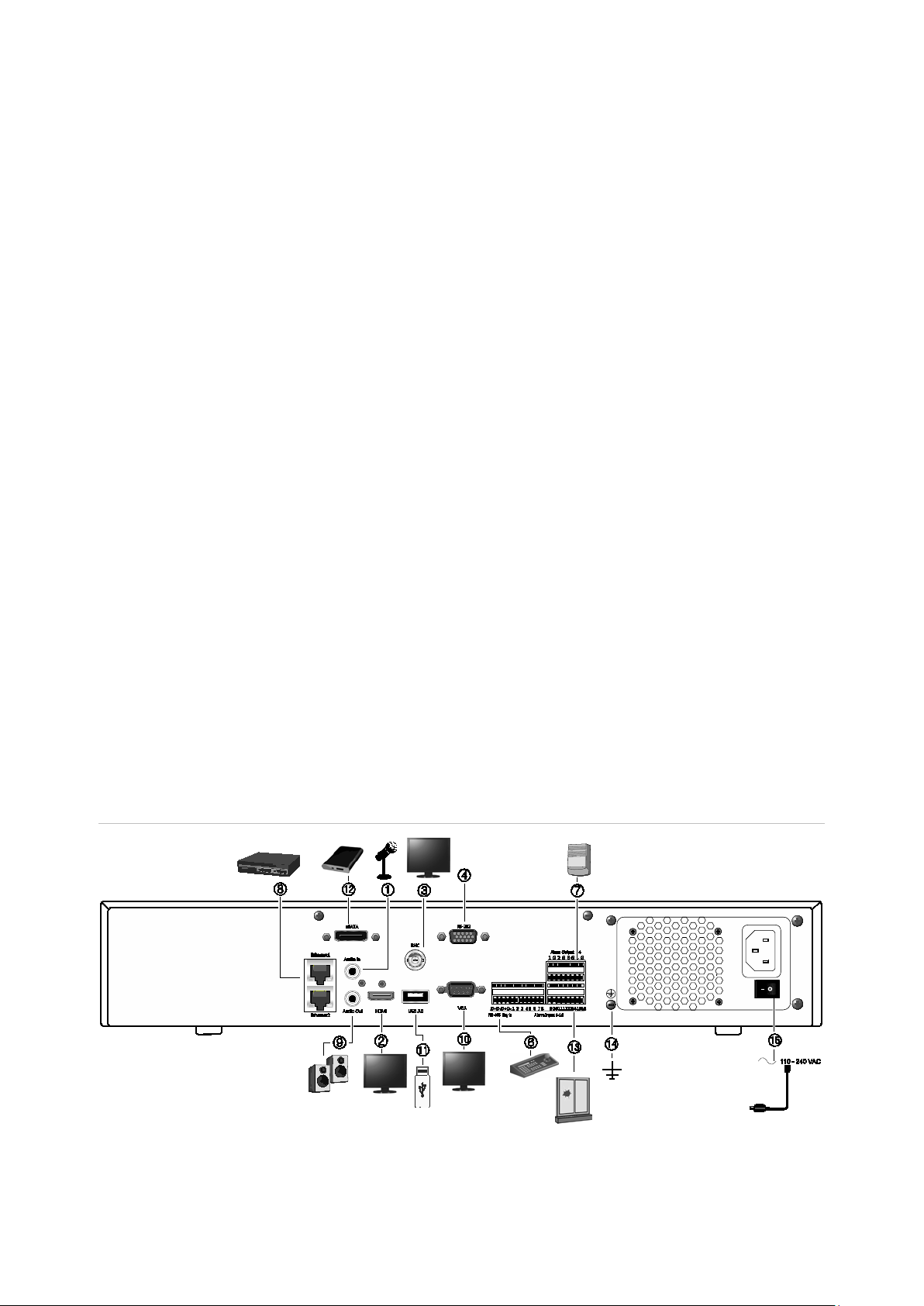
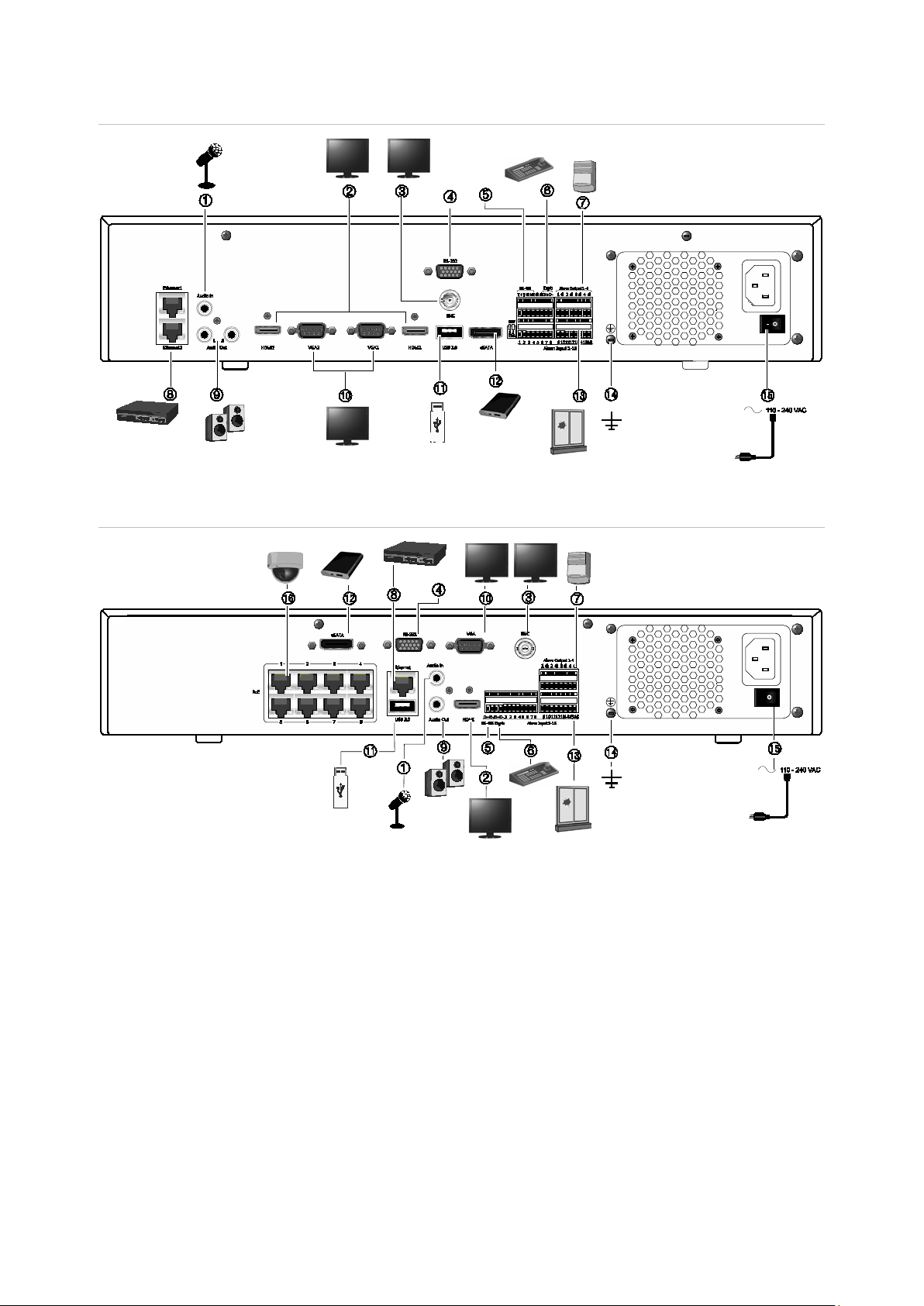
Back panel
The figures below show the back panel connections and describe each connector on a
typical TVN 22 digital video recorder. Details may vary for specific models.
Before powering up the recorder, insert the hard drives and connect a main monitor for
basic operation. Once all required connections are done, enter the relevant data in the
setup wizard (see page 8).
Note: For every hardwired alarm input, connect one wire to the input connection with
the alarm number label and one wire to a ground connection (labeled G).
Figure 1: TVN 22 back panel connections
4 TruVision NVR 22 (S/P) User Manual
Page 11
Chapter 2: Physical installation
9. Connect to speakers for audio output.
22S only)
Figure 1: TVN 22P back panel connections
Figure 2: TVN 22S back panel connections
1. Connect one audio input to RCA connectors.
2. Connect to an HDTV. The HDMI connection
supports both digital audio and video.
3. Connect one CCTV monitor (BNC-type
connectors).
4. Connect to a RS-232 device.
5. RS-485 port not used.
6. Connect to a keypad via RS-485 (KTD-405
shown).
7. Connect up to four alarm relay outputs.
8. Connect to a network (RJ45).
10. Connect to a VGA monitor.
11. Universal Serial Bus (USB). Connect to an
additional device such as a USB mouse,
CD/DVD burner, or USB HDD.
12. Connect to an optional eSATA device such as
SATA HDD, CD/DVD-RM.
13. Connect up to 16 alarm inputs (depending on
model).
14. Connect to ground.
15. Connect to a power cord. Use the power
switch to turn on/off the unit.
16. 8/16 PoE ports (depending on model). (TVN
TruVision NVR 22 (S/P) User Manual 5
Page 12
Chapter 2: Physical installation
RS-232 port
Use the RS-232 port to connect text interface devices or for use by technical support.
PoE ports
Connect up to 8 or 16 I P camer as t o the em b edd ed PoE por t s dep ending on the
TVN 22 model.
Monitor connections
The recorder supports up to 1280 × 1024 / 60 Hz resolution in VGA and 4K resol uti o n
in HDMI. The monitor resolution should be at least 800 × 600. Adjust your monitor
accordingly to this resolution.
The VGA or HDMI monitor can be used as the main monitor of the recorder. The BN C
video output can be used as event or alarm monitor.
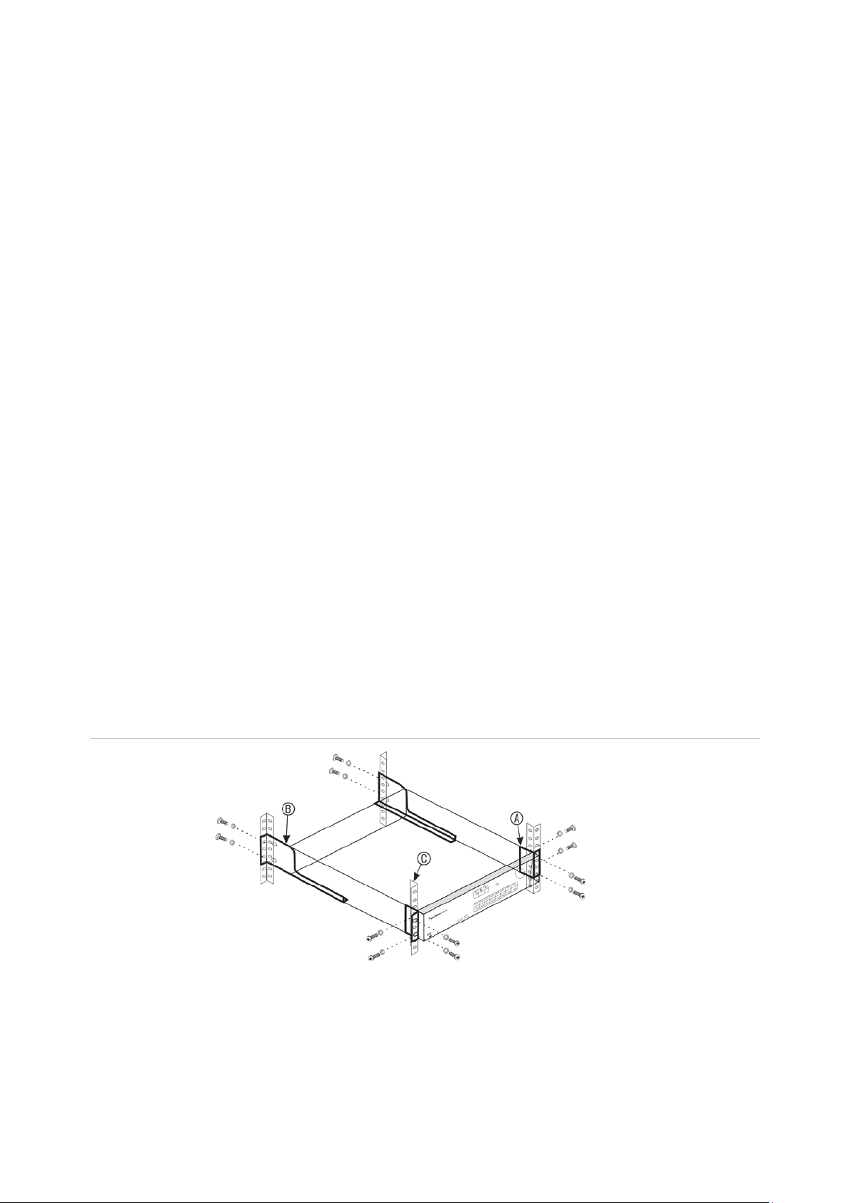
Rack mounting
The TVN 22 and 22S have a 1.5U desk based chassis. The TVN 22P has a 2U desk
based chassis. Both can be easily rack-mountable with the purcha se of the TVR-RK-1
rack-mount kit. Contact your local supplier to order the kit. See Figure 3 below.
Figure 3: TVN 22S rack-mount installation
To install the racks:
1. Attach the two small front-rack mount ears (A) to the NVR. The screws are supplied.
2. Attach the two large rear support brackets (not supplied) to the rear rails (B).
3. Attach the NVR to the front rails (C). The screws are not supplied.
6 TruVision NVR 22 (S/P) User Manual
Page 13

Chapter 3
Getting started
Powering on the recorder
Before starting the recorder, connect at least one monitor (HDMI or VGA). Otherwise,
you will not be able to see the user interface and operate the device.
The recorder auto-detects the video mode (PAL or NTSC) on startup.
It comes equipped with a universal power supply that will auto-sense 110/240 V,
60/50 Hz.
Note: It is recommended that an uninterruptible power supply (UPS) is used in
conjunction with the device.
To turn on the recorder:
Turn on the recorder using the power switch on the back panel. Once it is powered up,
the status LEDs on the front panel will light up.
To turn off the recorder:
1. In live view mode, right-click the mouse and click Menu > Shutdown.
2. In the Shutdown popup menu, select Shutdown. Click Yes to confirm shutdown.
You will be requested to enter the Admin password.
To reboot the recorder:
1. In live view mode, right-click the mouse and click Menu > Shutdown.
2. In the Shutdown popup menu, select Reboot. Click Yes to confirm reboot.
You will be requested to enter the Admin password.
TruVision NVR 22 (S/P) User Manual 7
Page 14

Chapter 3: Getting started
The startup wizard
The recorder has an express installation wizard that lets you easily configure basic
recorder settings when first used. It configures all cameras to default setti ngs. The
configuration of eac h c amer a and recorder can be customized as required.
By default the startup wizard will start once the recorder has loaded. It will walk you
through some of the more important settings of your recorder.
Any changes you make to a setup configuration page are saved when you exit the page
and return to the main wiz ar d page.
Note: If you want to set up the recorder with default settings only, click Next in each
screen until the end.
To use the Startup wizard:
1. To launch the startup wizard without rebooting the device, go to Menu > Device
Management > General Settings and click ‘Start wizard’.
2. Select the preferred language for the system and resolution from the drop-down list
and then click Next.
3. Enable or disable the option to start the wizard automatically when the recorder is
turned on. Click Next.
4. In each setup configuration page, enter the desired information and then click Next
to move to the next page. The setup configuration pages are:
Wizard setup pages Description
User configuration You can change the admin password and create additional
users. You must enter an admin password.
The default admin password is 1234.
Caution: It is strongly recommended that you change the
password of the administrator. Do not leave 1234 as the
default password. Write it down in a safe place so that you
do not forget it. If you should forget the password to your
recorder, contact your supplier with the serial number of
your recorder to obtain a secure code to reset it.
Time and date configuration Select the desired time zone, date format, system time,
and system date.
If Daylight saving time (DST) is required, check Enable
DST and enter the desired summer and winter times.
Note: The system time and date are visible on screen.
However, they do not appear in recordings.
Network configuration Configure your network settings such as the NIC type, IP
address, subnet mask, and default gateway. Enter the
preferred DNS server address as well as the alternate one
to use.
HDD management The hard drives are initialized at the factory. However if
you wish to clear all data, click Initialize to initialize the
HDD.
8 TruVision NVR 22 (S/P) User Manual
Page 15

Chapter 3: Getting started
Wizard setup pages Description
Adding IP cameras You do not need to search for TruVision PoE cameras.
They are automatically recogni zed when pl ugg ed in.
Click Search to find any available IP cameras on the LAN.
There are two ways to add an IP camera to the recorder
system:
Manually: Enter the IP address of the IP camera to be
added. Select the appropriate protocol, stream number,
and management port and then enter User name and
Admin password, and then click the Add button. Click,
Next to move to the next page.
Automatically: Select the desired IP cameras from the
search results list. Click Quick Add to add the selected
cameras to the recorder system without modifying the
camera configuration. The search list will display all
supported IP cameras that are located on the LAN.
Recording Configure your default recording settings as required. The
settings apply to all cameras connected to the recorder.
Check the Constant Recording checkbox for the recorder
to record continuously all day. If left unchecked, the
recorder will not record.
Check the desired time lapse check box, TL-Hi or TL-Lo.
To record motion detection events, check Event (Motion).
To record alarm events, check Alarm.
Note: You can configure the recording parameters of each
individual camera for the different recording schedules in
the recording menu.
5. When all the required changes have been entered, a summary page appears
showing all the settings.
Click Finish to exit the Wizard. The recorder is now ready to use.
For a description of the recorder main menu, see “Menu overview” on page 17.
Important! Your TruVision device is delivered with default user name and password
credentials for initial access, easy configuration, and auto discovery. For security
reasons, it is highly recommended to change the default credentials.
TruVision NVR 22 (S/P) User Manual 9
Page 16

Chapter 4
Operating instructions
Controlling the recorder
There are several ways to control the recorder:
• Front panel control. See “Using the front panel” below.
• Mouse control. See “Using the mouse” on page 14.
• IR remote control. See “Using the IR remote control” on page 15.
• TVK-800 keypad (from TVK-800 firmware version 1.0i). Please refer to the user
manual for more information.
Note: The TVK-800 keypad cannot decode H.265 cameras.
• Web browser control. See Chapter 18 “Using the web browser” on page 132 for
more information on using the web browser.
• Software (TruVision Navigator, TVRmobile or other video management or
integration software platforms). Please refer to the relevant user manuals of the
individual software platforms for more information.
You can use your preferred control method for any procedure, but in most cases we
describe procedures us ing the mouse. Optional control methods are given only when
they differ substantially from the mouse control methods.
Using the front panel
The function buttons on the front panel control can be used to operate most, but not all,
of the main functions of the recorder. The LED indicators light up to alert you of various
conditions. The functions available can be limited by setting passwords. See Figure 9
on page 11 for more in for ma ti on.
10 TruVision NVR 22 (S/P) User Manual
Page 17
Chapter 4: Operating Instructions
1
2
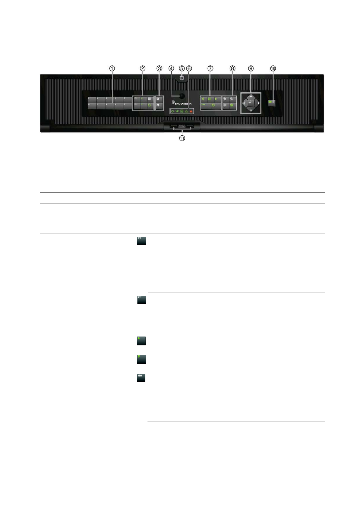
Figure 4: Front panel
8-channel model:
The controls on the front panel include:
Note: See Table 3 on page 13 for a detailed des cr i pti on of all these but t ons for dif fer ent
tasks.
Table 2: Front panel elements
Name Description
. Channel buttons Switch between different cameras in live, PTZ control or
playback modes.
Use the soft keyboard to enter numerals 0 to 9.
. Display buttons
F1: In Playback mode, click to start and stop video clipping. For
audio, press F1 and a numerical button to play the audio of the
specified camera in live view.
In System Information mode, get the DDNS URL. In User
Management mode, pop up the Permission screen of a selected
item in User Management > User > User Management. Delete a
selected item from USB flash drive. Exit the virtual keypad.
F2: In live view mode, 24-hour playback, and playback modes
press to display or hide the time or control bar. In PTZ mode,
stop all ongoing operations. Select or deselect an item. Enter a
selected folder of the external storage device, such as a USB
flash drive used for archiving.
A: In Live View mode, select the main monitor.
B: In Live View mode, select the event monitor.
Display: In multiview mode, toggle through the various
multiviews (full, quad, 1+5, 1+7, 9, and 16).
In HDD information mode and user management mode delete a
selected item. In PTZ mode, delete a selected key point. In Log
Search mode, display the details of a log file in Log Search
result.
TruVision NVR 22 (S/P) User Manual 11
Page 18

Chapter 4: Operating Instructions
3
4
5
6
7
8
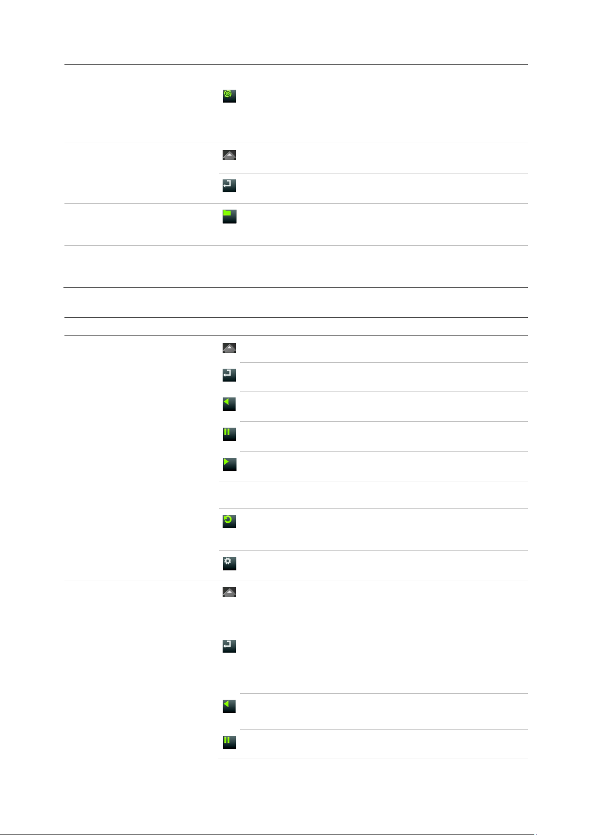
Name Description
. Menu and Search buttons
Seq: In Live View mode, start/stop sequencing cameras on the
current monitor.
Menu: Enter/exit the main menu.
Search: In live view, enter the advanced search menu.
. IR receiver Receiver for IR remote.
To connect the remote control to the recorder, press the Device
button, enter the device address, and press Enter. See Using
the IR remote control on page 15 for more information.
. Front panel lock You can lock or unlock the front panel with a key.
. Status LEDs
Power: A flashing green light indicates the recorder is working
correctly. Red indicates a fault.
Event Alarm: A steady red light indicates that there is a sensor
Alarm In or another alarm such as motion or tampering. No lig ht
indicates that there is no alarm.
HDD: HDD indicator blinks red when data is being read from or
written to the HDD. A steady red light indicates an HDD
exception or error.
Tx/Rx: Flashing green indicates a normal network connection.
No light indicates that it is not connected to a network.
. Playback buttons
. PTZ buttons
Technical Alarm: A steady red light indicates that there is a
technical alarm from the recorder. No light indicates that there is
no alarm.
Reverse: In live view mode, use to play back the earliest video.
In playback mode, playback a camera in the reverse direction.
Pause: In live view, freeze the last image of the live display for
all active cameras displayed. In playback mode, stop playback.
Play: In live view mode, play 24-hour playback of the current
camera (upper-left video tile if in multiview mode). In playback
mode, play back a camera in the forward direction. In search
mode, play back a selected video or view a snapshot. In PTZ
mode, do an auto tour.
Live: Switch to live view mode.
Replay: In playback mode, start playing the current file. Starts at
the beginning of the file.
Zoom +/-: In live view mode, playback mode, and PTZ control
mode use this button to zoom in and out. Also use them to
navigate within menus.
Preset: In PTZ Control mode, press Preset and a numeric
button to call the specified preset.
Also use to edit holiday mode, video search mode, HDD
selection mode, user management mode, bookmark
management, and bookmark search.
12 TruVision NVR 22 (S/P) User Manual
Page 19
Chapter 4: Operating Instructions
9
10
11
Task
Live view mode
Playback mode
advance the video by a
Name Description
. Direction
Enter button
. Archive button
. USB Interfaces Universal Serial Bus (USB) ports for additional devices such as
Table 3: Front panel button functions by task
Button
Tour: In PTZ Control mode, press Tour and a numeric button to
call the specified shadow tour.
Also use to scroll between calendar months and to navigate in a
text field.
The DIRECTION buttons are used to navigate between different
fields and items in menus.
The ENTER button is used to confirm selection in any of the
menu modes.
Press once to enter quick archive mode. Press twice to start
archiving. Indicator blinks green when data is being written to
backup device.
a USB mouse, CD/DVD burner, and USB Hard Disk Drive
(HDD).
Button function
Direction: Press to cycle through channels.
Enter: Press to show the PTZ control toolbar.
Reverse: Press to play the earliest video file of the current
camera (upper-left video tile if in multiview mode).
Pause: Press to freeze the last image of the live display for all
active cameras displayed.
Play: Press to play 24-hour playback of the current camera
(upper-left video tile if in multiview mode).
Live: Press to switch to live view mode.
Seq: Press to start/stop sequencing cameras on the current
monitor. Hold the Seq button for three seconds to start and stop
sequencing.
Menu: Press to enter the main menu.
Direction: The left and right buttons are used to speed up and
slow down recorded video (Single to 300X ) . The up and down
buttons are used to jump recorded video forwards or backwards
by 30 s.
Enter: Press the button to pause the video. Press again to
restart the video.
In single-frame Playback mode, press to
single frame.
TruVision NVR 22 (S/P) User Manual 13
Reverse: Press to play back a camera in reverse direction.
In Playback mode, play back a camera in the reverse direction.
Pause: In Playback mode, stop playback.
Page 20
Chapter 4: Operating Instructions
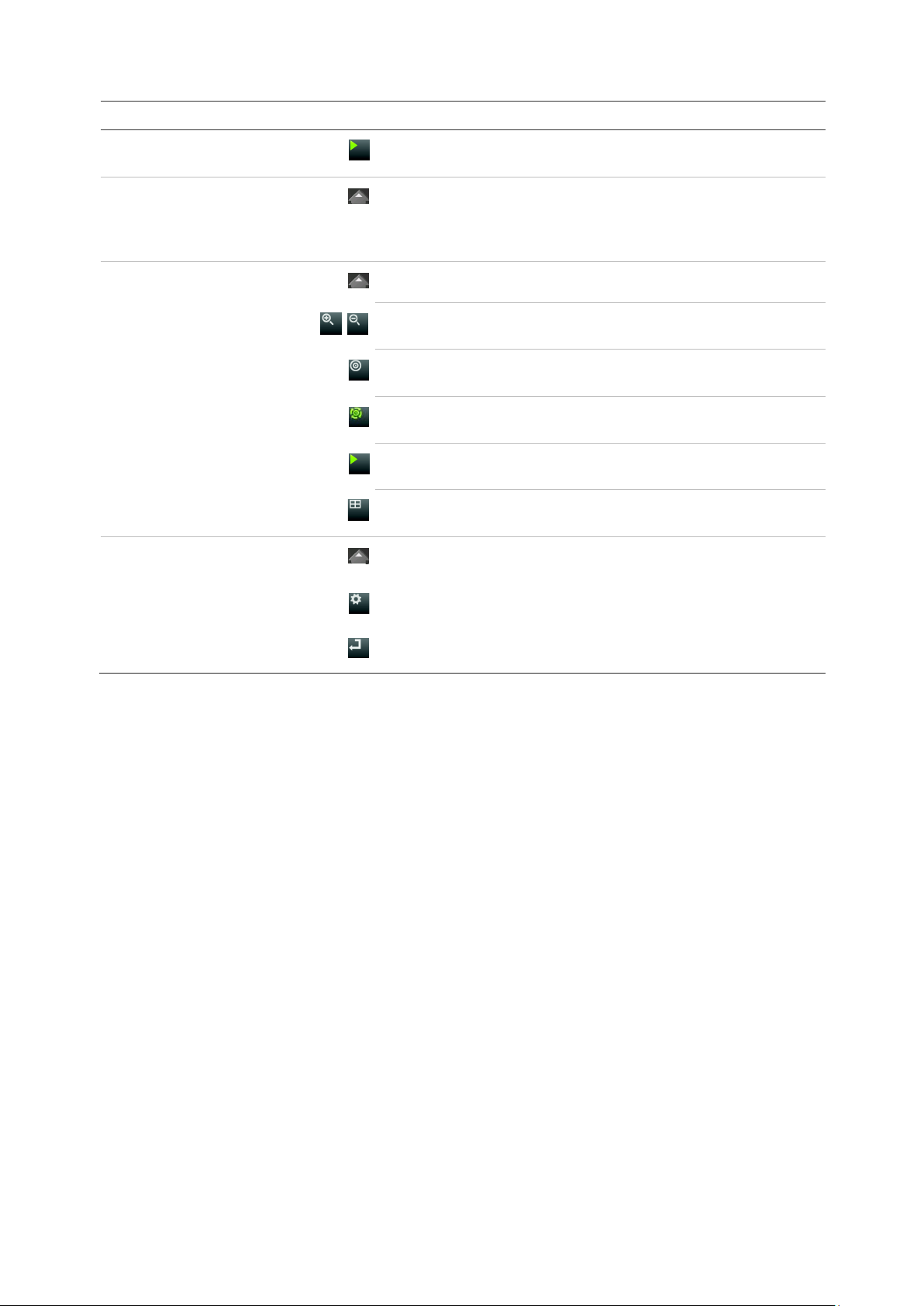
Task
Pause mode
PTZ control mode
Menu navigation
Button
Button function
Play: In Playback mode, play back a camera in the forward
direction.
Direction: The left and right buttons are used to jump recorded
video forwards or backwards by one frame. The up and down
buttons are used to jump recorded video forwards or backwards
by one second.
Direction: Press to control the movement of the PTZ camera.
Zoom +/-: Press to zoom in and out.
Preset: Press Preset and a numeric button to call the specified
preset.
Tour: Press Tour and a numeric button to call the specified
shadow tour.
Play: Press to do an auto tour.
Display: Press to delete a selected key point from the PTZ
Setting > More Settings> Tour > Key Point list.
Direction: Press to navigate between different fields and items
in menus.
Menu: Enter/exit the main menu.
Enter: Press to confirm the selection in any of the menu modes
Using the mouse
The USB mouse provided with the recorder can be used to operate all the functions of
the unit, unlike the fron t panel whi c h has limi t ed f uncti o nal i ty. It lets you navigate and
make changes to settings in the user interface.
Connect the mouse to the recorder by plugging the mouse USB connector into the USB
port on the back panel or the front panel. The mouse is immediately operational and the
pointer should appear.
Note: Use a USB 2.0 (front panel) or 3.0 (back panel) mouse.
You can purchase a spare mouse by ordering part number TVR-MOUSE-1.
See Table 6 on page 15 for a description of the mouse buttons.
14 TruVision NVR 22 (S/P) User Manual
Page 21

Chapter 4: Operating Instructions
Item
Left button
Right button
Scroll
Table 4: Mouse buttons
Description
Single-click Live view: Select a camera to display the live view toolbar.
Menu: Select a component of a menu, such as a button or
an input field. This is similar to pressing the Enter button
on the remote/front panel controls.
Double-click Live view: Switch between single screen and multi-screen
mode in live/ playback mode.
Click and Drag Live view: Drag channel/time bar.
PTZ control: Adjust pan, tilt, and zoom .
Tamperproof, privacy masking and motion detection
functions: Select the target area.
Digital zoom-in: Drag and select target area.
Single-click Live view: Display menu.
Menu: Exit the current menu and return to higher level.
-wheel Scroll Up Live view: Return to the previous window.
Menu: Move the selection to the previous item.
Scroll Down Live view: Move to the next window.
Menu: Move the selection to the next item.
Using the IR remote control
The recorder is supplied with an infrared (IR) remote control unit. Like the mouse, it can
be used to operate all of the main functi ons of the unit.
You can program the IR remote control with a unique device ID address so that the
controller will only be able to communicate with recorders with that address. No
programming is necessary if using a single recorder.
The device ID address only applies when using a remote control and not when using a
keypad.
You can purchase a replacement remote control by ordering part number TVRREMOTE-1.
TruVision NVR 22 (S/P) User Manual 15
Page 22
Chapter 4: Operating Instructions
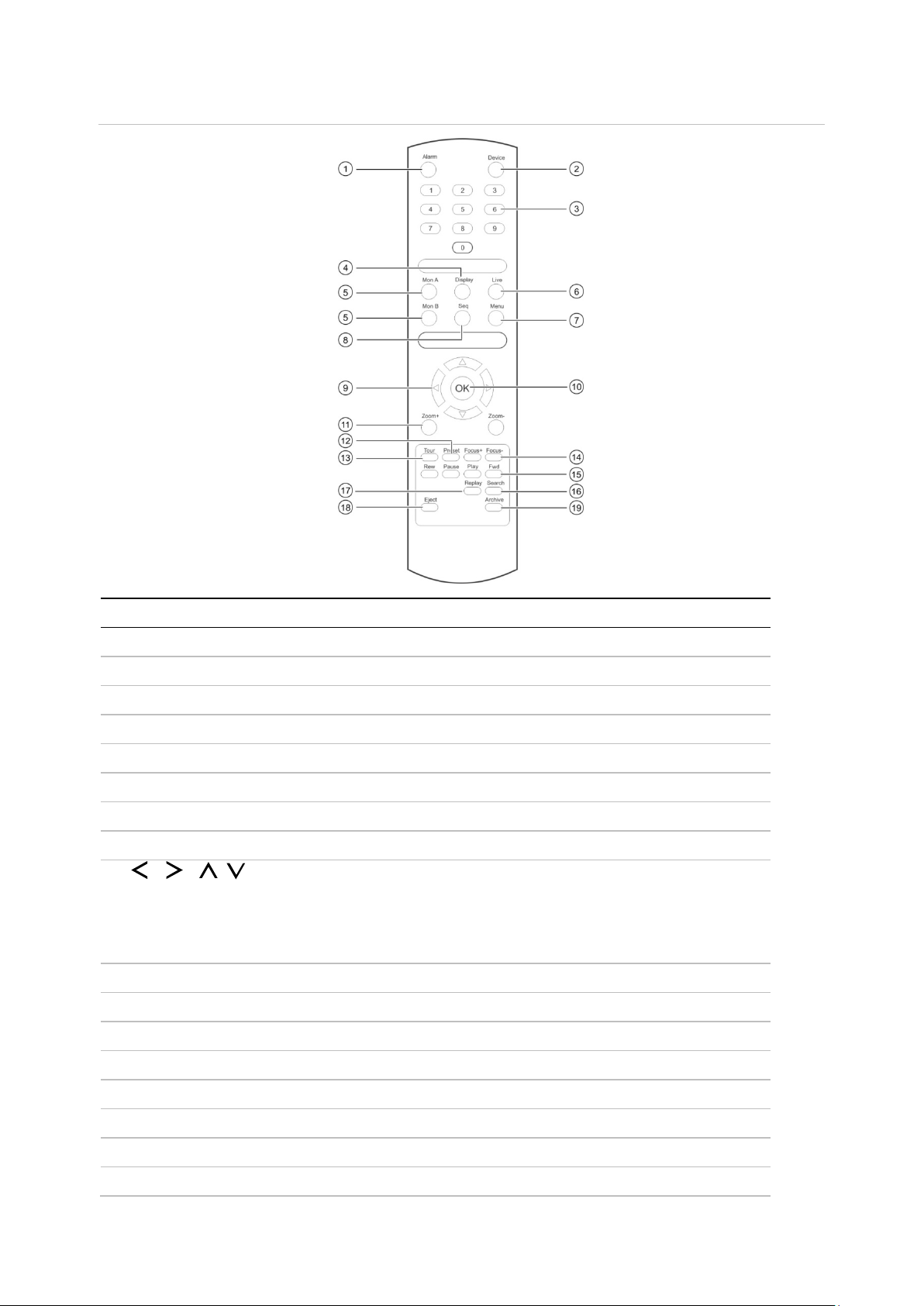
Item
Description
1
Acknowledge an alarm.
2
Enable/disable the IR remote control to control the
3
Select a camera, and enter a number in a menu option.
4
Switch between the different multiview formats
5
Switch
6
Return to
7
Activate the main menu.
8
Start /stop sequencing.
9
In Menu mode: Use left or right
arrow buttons to edit entry.
In PTZ mode: Use to control PTZ.
In Playback mode: Use to control playback speed.
10
Confirm selection.
11
Use to control zoom of
12
Enter preprogrammed three
13
Enter preprogrammed three
14
Use to control focus of camera lens
15
Use to control playback (Rewind, Pause, Play, and Fast Forward).
16
Open the Search menu.
17
Replay the selected file from the beginning.
Figure 5: IR remote control
. Alarm
. Device
. Numeric buttons
. Display
. Mon A and Mon B
. Live
. Menu
. Seq
. , , ,
. OK
. Zoom + and -
recorder.
.
between monitors A and B.
live view mode.
arrow buttons to select and up or down
camera lens.
. Preset
. Tour
. Focus + and . Playback control
. Search
. Replay
16 TruVision NVR 22 (S/P) User Manual
-digit code to call up a preset.
-digit code to call up shadow tour.
.
Page 23

Chapter 4: Operating Instructions
Item
Description
18
Eject the CD or DVD disk.
19
Press once to enter quick archive mode. Press twice to start archiving.
. Eject
. Archive
Aim the remote control at the IR receiver located at the front of the unit to test
operation.
To change the address of the remote control to the recorder:
1. Press the Menu button on the front panel or right-click the mouse and select the
Menu button. The default display menu window appears.
2. Click Device Management > General Settings.
3. Check the remote control ID value. The default value is 255. This device address is
valid for all IR controls.
Note: The recorder will respond to any remote control that has an address between
1 and 255.
4. On the remote control press the Device button.
5. Enter the device address value. It must be the same as that on the recorder.
6. Press the OK button on the remote control.
To place batteries into the IR remote control:
1. Remove the battery cover.
2. Insert the batteries. Make sure that the positive (+) and negative (−) poles are
correctly placed.
3. Replace the battery cov er .
Troubleshooting the remote control
If the IR remote control is not functioning properly, perform the following tests:
• Check the battery polarity.
• Check the remaining charge in the batteries.
• Check that the IR remote control sensor is not masked.
If the problem still exists, please contact your administrator.
Menu overview
The recorder has an intuitive structure that allows you to configure the unit’s
parameters quickly and efficiently. Each command icon displays a window that lets you
edit a group of settings. Most menus are available only to system administrators.
TruVision NVR 22 (S/P) User Manual 17
Page 24
Chapter 4: Operating Instructions
Display Settings
video format, resolution,
Camera Setup
OSD, privacy masking,
Network
Recording
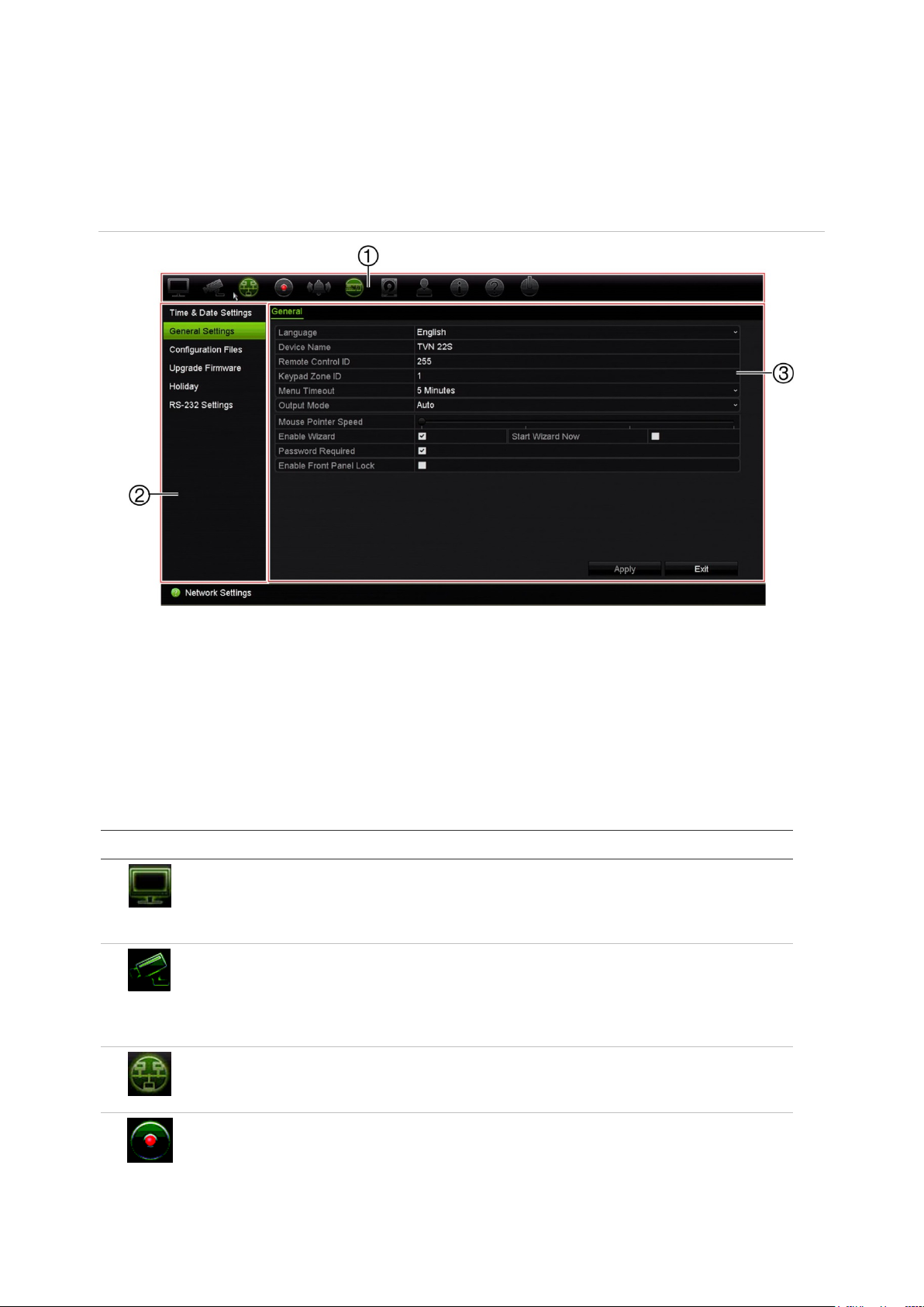
The window is divided into three sections. The currently selected command icon and
submenu item are highlighted in green. See Figure 6 below.
You must be in live view mode to access the main menu.
Figure 6: Menu structure
1. Menu toolbar: Setup options available for the selected menu function. Move the mouse over a
command icon and click to select it. See Table 5 below for a description of the icons.
2. Submenu panel: Submenus for the selected menu function are displayed. Click an item to select it.
3. Setup menu: All the details for the selected submenu are displayed. Click a field to make changes.
Note: See Table 3 on page 11 for the description on how to access the menu options
using the front panel.
Table 5: Description of the menu toolbar icons
Icon Name Description
Configures display settings including
Configures camera settings including snapshot resolution
video output interface, dwell time, multiview format, and
camera sequencing. See Chapter 9 “Display settings” on
page 52.
and quality, camera settings including
tampering, motion detect io n setup, PTZ presets and shadow
tours, V-stream encoding and people counting. See
Chapter 10 “Camera setup” on page 56
Settings Configures standard network settings including IP address,
Configures recording settings including instant playback
18 TruVision NVR 22 (S/P) User Manual
email notifications, DDNS setup, and advanced network
settings. See the Chapter 11 “Network settings” on page 74.
duration, recording schedule, manual recording and hot
spare. See Chapter 12 “Recording” on page 84.
Page 25

Chapter 4: Operating Instructions
Alarm and Event
Setup
Device Management
Storage Management
User Management
System Information
Help
Shutdown
Icon Name Description
Configures alarm settings including alarm input, alarm output,
manual trigger, alarm notifications, video loss, alarm host
setup, and intrusion panel and zone setup (OH inte gratio n) .
See Chapter 13 “Alarm and event setup” on page 91.
Configures system settings including system date and time,
DST, language, menu timeout, import/export config files,
firmware upgrade, holiday schedules and RS-232 settings.
See Chapter 14 “Device management” on page 105.
Configures HDD information, storage mode, S.M.A.R.T.
settings, bad sector detection and RAID. See Chapter 15
“Storage management” on page 112.
Configures users, passwords, and access privileges. See
Chapter 16 “User management” on page 121.
Displays device information, camera setup information,
recording setup information, alarm inputs information, alarm
outputs information, network information, HDD information,
and log search. See Chapter 17 “System information” on
page 126.
Provides reference information to the various toolbars,
menus, and keys within the interface.
Provides access to logout, reboot, and shutdown options.
See “Powering on the recorder” on page 7.
To access the main menu:
1. In live view, press the Menu button on the remote control or front panel.
- Or Right-click the mouse and select Menu from the pop-up menu.
The main menu window appears . The Di spl a y Settings window appears by default.
2. Click the required menu icon to display its submenu options. Modify the
configuration parameters as required.
3. Click Apply to save the settings.
4. Click Exit to leave the menu setup and return to live view.
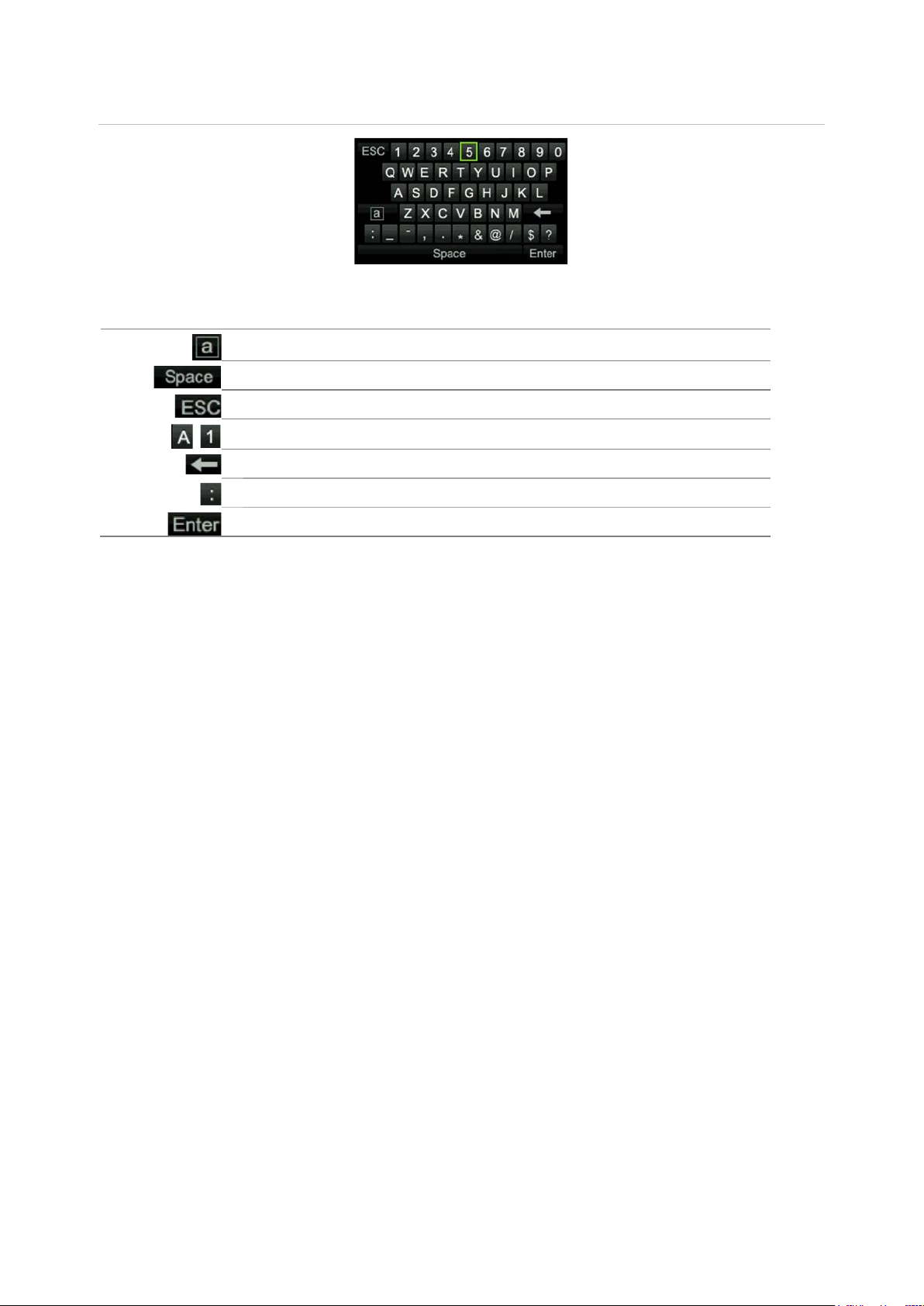
The soft keyboard
A keyboard will appear on-screen when you need to enter characters in a window
option. Click a key to input that character.
TruVision NVR 22 (S/P) User Manual 19
Page 26
Chapter 4: Operating Instructions
Switch to lowercase/upperc
Space
Exit the soft keyboard
Alphanumeric characters
Backspace
Punctuation
Confirm selection
Figure 7: The soft keyboard
Description of the keys in the soft keyboard:
ase
Exiting the main menu
Press the Menu button on the front panel to exit the current menu window and return to
live view, or click Exit in a main menu, or right-click using the mouse.
20 TruVision NVR 22 (S/P) User Manual
Page 27
Icon
Chapter 5
Live view
Description of live view
Live view mode is the normal operating mode of the unit where you watch live images
from the cameras. The recorder automatically enters into live view mode once powered
up. On the monitor you can see whether a recording is in progress and, if set up to do
so, the current date and time, as well as the camera name.
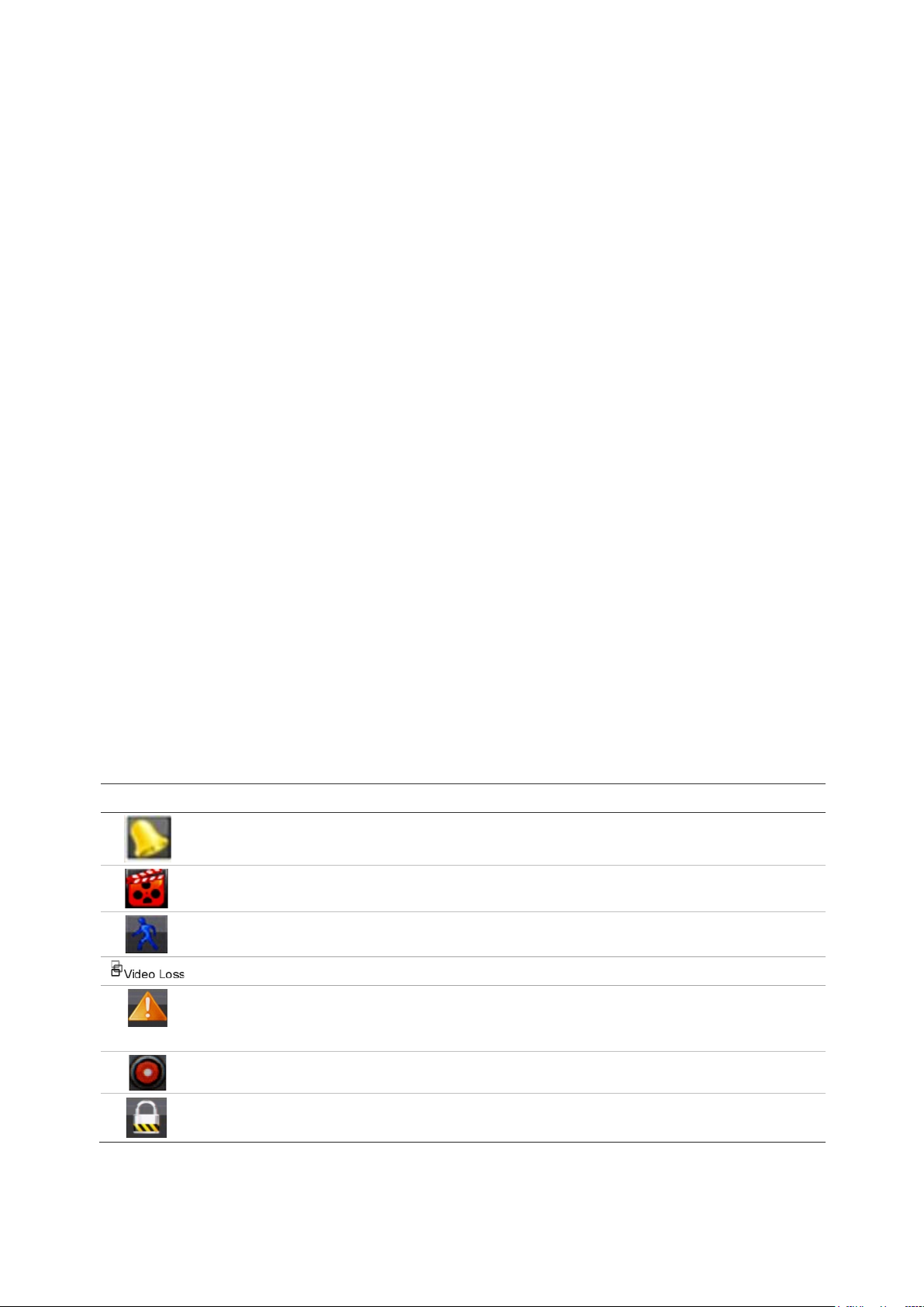
Status information
Information on the system and camera status is displayed as icons on the main and
auxiliary monitors. The camera status icons are shown for each camera. Each icon
represents information on a specific item. These icons include:
Table 6: Description of the on-screen status icons
Description
Indicates an alarm.
Indicates that a camera channel is being recorded.
Indicates a motion detection event.
Indicates a video loss event .
Indicates alarm and system event notifications. Clicking the event hint icon opens the
Alarm Center window that lists all the alarm and event notifications. See “Event
notifications” on page 95 for more information.
Indicates manual recording.
Indicates that live view is locked from the front panel. Mouse actions are still allowed.
The recorder can display more than one icon at the same time.
TruVision NVR 22 (S/P) User Manual 21
Page 28
Chapter 5: Live View
1.
2.
The system status is displayed on the front panel by the status LEDs.
Video output
The recorder automatically checks the monitor outputs used on startup.
If an HDMI monitor is used, it will be the main output. If HDMI and VGA monitors are
both connected to the recorder, both will be main monitors; they will both show the
same view.
The TVN 22P has two HDMI and two VGA ports. If the HDMI 4K resolution setting is
used, the second HDMI port is disabled.
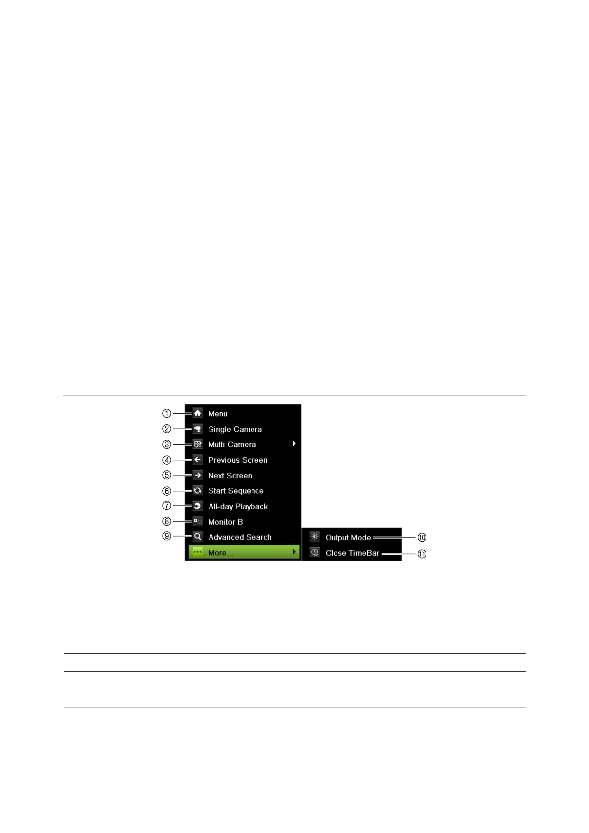
Live view mouse menu
Many features of live view can be quickly accessed by placing the cursor on a live
image and clicking the right-but ton o f the mou s e. The mouse menu appears (see
Figure 8 below).
Figure 8: The mouse menu for the monitor A
The list of commands available depends on which monitor is active; main or auxiliary
(monitor B). See Table 7 below. The default settings of these commands are provided
in the appendix under “Default menu setti ng s ” on pag e 153.
Table 7: Mouse menu for monitor A (main monitor)
Name Description
Menu Enter the Main menu.
Note: Not available for monitor B.
Single Camera Switch to a full-screen view for the selected camera from the drop-
down list. See “Single and multiview display mode” on page 23 for
more information.
22 TruVision NVR 22 (S/P) User Manual
Page 29

Chapter 5: Live View
3.
4.
5.
6.
7.
8.
9.
10
11
Name Description
Multi Camera Switch between the different multiview options from the drop-down
list. See “Single and multiview display mode” below for more
information.
Previous Screen Displays the previous camera.
Next Screen Displays the next camera.
Start Sequence Turn on sequence mode. The window automatically sequences
between cameras. To set up the sequence dwell time, go to Menu >
Display Settings > Display > Sequence Dwell Time and select a
value.
Note: Not available for monitor B.
24-hour Playback Playback the recorded video of the selected day from the selected
camera. The current day is selected by default.
Mon itor B/Monitor A Switch between monitors A (main) and B (event).
Advanced Search Enter the advanced video search menu. See “Search video menu” on
page 41 for more information.
Note: Not available for monitor B.
. Output Mode Select Standard, Bright, Soft, or Vivid mode to display.
. Close TimeBar Open/close the time bar.
Single and multivie w display mode
The recorder has single and multiview formats. The number of multiview display modes
available depends on the recorder model.
Single view display
format
Multiple view dis play
format
Press the numeric button on the front panel to switch to the corresponding
camera display. For example, press button 10 to v iew cam er a 10.
-OrRight-click the mouse and select Single Camera from the menu. Select the
required camera from the list.
Press the Display button on the front panel to cycle through different display
formats.
-OrRight-click the mouse and select Multi Camera from the menu. Select the
desired multiview display layout.
TruVision NVR 22 (S/P) User Manual 23
Page 30
Chapter 5: Live View
Sequencing cameras
The sequencing feature allows a camera to be displayed briefly on screen, before
advancing to the next camera in the sequence list. Sequencing can only be done in
single-view display mode.
The default sequence displays each camera in numerical order. However, each camera
on the main and event monitors can have a pre-programmed dwell time and seque nc e
order. See “Layout” on page 54 for more information.
Note: Dwell time must not be set to zero for sequencing to function.
Sequencing cameras using the front panel:
Select the camera where you want to start sequencing. Press the button on the
front panel to start sequencing. Press it again to stop sequencing.
Sequencing cameras using the mouse:
Select the camera where you want to start sequencing. Right-click the mouse and
select Start Sequence to start the sequencing. Right-click again and select Stop
Sequence to stop sequencing.
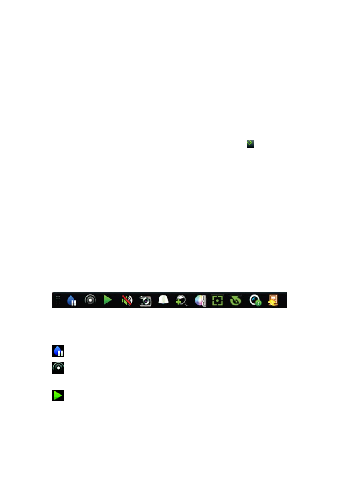
Live view toolbar
The live view toolbar lets you quickly access regularly used commands. Position the
cursor over a video tile and left-click the mouse. The toolbar app ear s (see Figure 9
below).
Figure 9: Live view toolbar
Table 8: Description of the live view toolbar icons
Icon Description
Pause: Freeze the live image of the selected camera. Although the image pauses, time
and date information does not. The system clock continues to run.
Start Manual Recording: Start/stop manual recording.
The icon is red when manual recording is enabled. See “Recording schedule” on page
84 for information on setting up this function.
Instant Playback: Playback the recorded video from the last five minutes. If no
recording is found, then there was no recording made in the last five minutes.
Click the icon and select the desired camera. Click OK.
See “Modify the instant playback duration” on page 87 for more information.
24 TruVision NVR 22 (S/P) User Manual
Page 31

Chapter 5: Live View
Icon Description
Audio On: Enable/Disable audio output. The stream type must be set to Video/Audio.
See “Camera recording settings” on page 60 for further information.
Snapshot: Capture a snapshot of a video image. The image is saved on the unit. See
“Search snapshots” on page 32 for further information.
PTZ Control: Enter PTZ control mode.
See “PTZ presets and tours” on page 26 for more information.
Digital Zoom: Enter digital zoom. See “Digital zoom ” on page 25 for further information.
Image Settings: Enter the image settings menu to modify the image lighting levels .
There are two options:
Preset Mode: These are preconfigured image lighting levels. Select one of the four
options depending on current lighting conditions:
- Standard: Use in standard lighting situations.
- Indoor: Use indoors.
- Dim Light: Use when the light l e v el is low.
- Outdoor: Use when outdoors. The contrast and saturation values are high.
Customize: Modify brightness, contrast, saturation, and hue values. Click Restore to
restore image settings to previous values.
Click Restore to restore image settings to previous values. Click Default to return to
default values.
These settings can also be modified from the Camera Setup > Image menu (see page
“Image settings” on page 63.
Auxiliary Focus: Automatically focus the camera lens for the sharpest picture.
Lens Initialization: Initialize the lens of a camera with a motorized lens, such as PTZ
or IP cameras. This function helps to maintain lens focus accuracy over prolong periods
of time.
Stream Information: Display the real-time frame rate, bit rate, resolution and video
compression.
Close Toolbar: Close the toolbar.
Digital zoom
You can easily zoom in or out of a camera image in live view mode and playback using
the digital zoom command. The zoom command magnifies the camera image four
times. See Figure 10 below.
TruVision NVR 22 (S/P) User Manual 25
Page 32

Chapter 5: Live View
Figure 10: Digital zoom window
To quickly zoom in/out on a camera image:
1. Left-click the mouse on the desired camera. The live view toolbar appears.
2. Click the digital-zoom icon. The digital view window appears.
3. Left-click the mouse and drag the red square to the area of interest, or press the
arrow buttons on the front panel to position the red square. The selected area is
magnified.
4. To exit digital zoom, right-click the mouse.
PTZ preset and tours
When in live view you can quickly call up the list of existing presets, preset tours, and
shadow tours by using the front panel, remote control, mouse, and keypad.
Front panel Press (Enter). PTZ control panel appears.
Mouse Left-click the mouse on the desired camera image. The live view toolbar appears.
Click the PTZ control icon to enter PTZ mode. The PTZ control panel appears.
Remote control Press the OK button. The PTZ control panel appears.
Keypad Press the Enter button on the keypad.
If the display was in multiview format, it changes to full-screen for m at for the selected
camera. See Figure 11 on page 27 for a description of the PTZ control panel.
26 TruVision NVR 22 (S/P) User Manual
Page 33

Chapter 5: Live View
1.
2.
3.
4.
5.
6
Figure 11: PTZ control panel
Table 9: Description of the PTZ control panel
Name Description
Directional pad/auto-
scan buttons
Zoom, focus, and iris Adjusts zoom, focus, and iris.
PTZ movement Adjusts the speed of PTZ movement.
Toolbar
Select PTZ command Displays the desired function from the scroll bar: Camera, Preset,
. Exit Exits the PTZ control panel.
Controls the movements and directions of the PTZ. The center
button is used to start auto-pan by the PTZ dome camera.
Turns on/off camera light (not used).
Turns on/off camera wiper (not used).
Zoom area.
Centers the PTZ dome camera image. This command is
not supported on all PTZ dome cameras.
Jumps to the home position.
Preset Tour or Shadow Tour.
To call up a preset:
1. In live view, left-click the mouse and select the PTZ control icon in the quick access
toolbar. The PTZ control panel appears. Select the desired camera from the toolbar.
– Or –
On the front panel, select the desired camera and press (Enter) to call up the
PTZ control panel.
2. Scroll the control panel to Preset and double-click the desired preset from the list.
The camera immediately jumps to the preset position.
TruVision NVR 22 (S/P) User Manual 27
Page 34

Chapter 5: Live View
To call up a preset tour:
1. In live view, left-click the mouse and select the PTZ control icon in the live view
toolbar. The PTZ control panel appears. Select the desired camera from the toolbar.
– Or –
On the front panel, select the desired camera and press call up the PTZ control
panel.
2. Scroll the control panel to Tour and double-click the desired preset tour from the list.
The camera immediately carries out the preset tour movement.
To call up a shadow tour:
1. In live view, left-click the mouse and select the PTZ Control icon in the live view
toolbar. The PTZ control panel appears. Select the desired camera from the toolbar.
– Or –
On the front panel, select the desired camera and press call up the PTZ control
panel.
2. Scroll the control panel to Shadow Tour and double-click the shadow tour from the
list. The camera immediately carries out the shadow tour movement.
28 TruVision NVR 22 (S/P) User Manual
Page 35

Search type
Time and D
Event
Bookmark
Snapshot
Chapter 6
Searching files
This chapter describes how to search and playback recorded videos as well as search
them by time, events, bookmarks, and snapshots.
Advanced search video menu
You can easily search and play back recorded videos by time and date, events,
bookmarks, and snapshots.
Figure 12: The Advanced Search menu
The Search window has four submenus that allow you to carry out different searches by
theme:
Description
ate Search all video by time and date of recording.
Search only event recorded files. Files can be searched by alarm inputs, text
insertion, or intelligent alarms.
Search recorded files with bookmarks.
Search snapshots.
TruVision NVR 22 (S/P) User Manual 29
Page 36

Chapter 6: Searching files
overwritten.
Search results
A search will usually produce a list of recording files, which may extend to several
pages. The files are listed by date and tim e. T he most r ecent file is listed first. You ca n
then select a file to play it back. See Figure 13 below for an example of a search.
A recording file can be up to 1GB in size. Every day at midnight a new recording file is
started, and each event is also stored as a separ ate recor di ng fil e.
Only one file can be played back at a time.
Figure 13: Example of a search result list
1. Click to lock recording to prevent it from being
2. Click to playback the selected video.
Search and play back recordings by time and video type
You can search recorded video by time and video type, such as continuous recordings,
alarms and all recordings. Video can be played back simultaneously across several
cameras.
To search archived video files:
1. In live view, right-click the mouse on the desired video pane and select Search
Video.
– Or –
Click the Search icon on the front panel.
2. Select the desired cameras, record type, file type as well as start and end times of
3. Click Search. The list of search results appears.
4. Click to play back the search results:
30 TruVision NVR 22 (S/P) User Manual
The Search menu appears.
the recording.
Page 37

Chapter 6: Searching files
To immediately access archived footage:
1. In the Search menu, click the “Time & Date” tab.
2. Select the desired cameras, record type, file type as well as start and end times of
the recording. Up to four cameras can be selected.
3. Click Go. The simultaneous playback of up to four cam eras for the indi cated time
will start.
Search and play back recordings by event
You can search recorded video by event type: motion, VCA alarms, and alarm input .
To play back search results:
1. In live view, right-click the mouse on the desired video pane and select Search
Video.
– Or –
Click the Search icon on the front panel.
The Search menu appears.
2. In the Search menu, click the “Event” tab.
3. Select the desired event type as well as start and end times of the recording.
4. Select the desired alarm inputs or channels.
If you selected “Intelligent Alarm” as the event type, select the required IP cameras.
5. Click Search. The list of search results appears.
6. Select the desired video from the list.
7. In the search results window, you can:
- Click Play to playback the footage
- Click Archive to archive results
- Click Details to display more information about an event.
Note: You can modify the pre- and post-play periods of a recording.
Search bookmarked recordings
For information on creating bookmarks, see “Create bookmarks” on page 45.
TruVision NVR 22 (S/P) User Manual 31
Page 38

Chapter 6: Searching files
To search for a bookmark:
1. In live view, right-click the mouse on the desired video pane and select Search
Video.
– Or –
Click the Search icon on the front panel.
The Search menu appears.
2. In the Search menu, click the “Bookmark” tab.
3. Select the desired cameras as well as start and end times of the recording to be
searched. Also select the type of bookmark to be searched.
If searching for customized bookmarks, enter a keyword from the bookmark name.
Click Search. The list of bookmarks appears.
4. Select the desired book mark from the list.
5. Select a bookmark and do one of the following:
Click the Edit button to edit a bookmark’s name.
- Or Click the Delete button to delete a bookmark.
- Or Click the Play button to play back a bookmark.
Search snapshots
You can search video snapshots. See “Live view mouse menu” on page 22 on how to
create snapshots.
To search for snapshots:
1. In live view, right-click the mouse on the desired video pane and select Search
Video.
– Or –
Click the Search icon on the front panel.
The Search menu appears.
2. In the Search menu, click the “Snapshot” tab.
3. Select the desired cameras as well as start and end times of the recording to be
searched.
4. Click Search. The list of snapshots appear s .
5. Select a snapshot to see it in the thumbnail window. Click its Play button to see
it in full-screen mode.
32 TruVision NVR 22 (S/P) User Manual
Page 39

Chapter 6: Searching files
6. When in full-screen mode, move the cursor to the right edge of the window to see
the complete list of snapshots found in the search. Click their Play buttons to see
them in full-screen mode.
7. To see a slideshow of all the snapshots found, click the or buttons on the
snapshot toolbar to sequence forwards or backwards through the shots.
Log search
You can open video footage from the results of a log search. Refer to “Search the
system log” on page 129 for more information.
TruVision NVR 22 (S/P) User Manual 33
Page 40

Chapter 7
Playback functionality
The recorder lets you quickly locate and play back recorded video. There are multiple
ways to play back video:
Instant playback of the most recently recorded video
24-hour playback of one day’s recorded video
Search video by specific time, events, bookmarks, or snapshots (see Chapter 6
“Searching files” on page 29 for further infor m ati on)
Launch playback of video associated to searched events
The recorder continues to record the live view from a camera while simultaneously
playing back video on that camera display. You must have the access privilege to play
back recordings (see “Customize a user’s access privileges” on page 122 for more
information).
34 TruVision NVR 22 (S/P) User Manual
Page 41

Chapter 7: Playback functionality
manually.
Figure 14: Playback window (24-hour playback shown)
1. Playback mode: Select one of seven
playback modes to view: Normal, Event,
Bookmark, Smart, Sub-periods, External
File, or Snapshot. See “24-hour playback ”
on page 38 for more information.
2. Playback viewer.
3. Full screen.
4. Exit 24-hour playback recording.
Click Exit or right-click the mouse to
return to live view.
5. Quick camera select:
Max. Camera for Playback: From the
camera list, automatically selects the first
16 cameras with recordings.
Min. Camera for Playback: From the
camera list, automatically select the first
camera with recordings.
Note: Cameras can also be selected
manually. The maximum number of
cameras that can be selected is 16,
whether selected autom atically or
6. Camera panel. Select the cameras for
playback. Move the mouse over the area to
display the list of cameras available.
7. Calendar panel.
White: No recordings.
Green/Yellow/Red/Pale green/Magenta:
Recordings available on the recorder.
8. Playback control toolbar. See Figure 15 on
page 36 for more information.
9. Time bar: Time of actual playback. This is only
displayed in 24-hour playback.
10. 24-hour recording progress bar: This bar
displays how much of the 24-hour period has
been recorded.
11. Recording type: Description of the color coding
of recording types that appear in the playback
progress bar. Green indicates constant
recording. Yellow indicates motion recording.
Red indicates alarm recording. Pale green
indicates manual recording. Magenta indicates
VCA recording.
The playback control toolbar
It is easy to manually control playback using the playback control toolbar. See
Figure 15 on page 36.
Note: The playback control toolbar does not appear for instant playback.
TruVision NVR 22 (S/P) User Manual 35
Page 42

Chapter 7: Playback functionality
1
2
3
4
5
Figure 15: Playback control toolbar (Search playback example shown)
Description
. Playback bar: This bar displays the playback recording. It indicates in color the type of recording.
Constant recording is shown in the example above.
. Timeline: Allows you to jump forwards or backwards in time. The timeline moves left (oldest
video) to right (newest video). Click a location on it for where you want playback to start.
In 24-hour playback, the cursor shows the actual time.
In search playback, the cursor is a ball. The actual playback time of the ball position and how
much playback has already played are also displayed.
. Zoom in and out of the recording.
. Audio and video control toolbar:
/ Audio on/off. When audio is On, use the scale to adjust the volume.
/ Start/stop a video clip during playback. Sections of a recording can be saved to an
external storage device.
Lock a file during playback.
Quick snapshot. Click to take a snapshot of the recording.
Add default bookmark.
Add customized bookmark.
File management.
Click to see the list of video clips, snapshots, locked files, bookmarks and their times.
The video clips, playback captures and locked files can be archived. Bookmarks can
be renamed and deleted.
Digital zoom.
Click to enter the digital zoom function. Click again to exit.
Archive files.
Modify the forward and reverse skip times.
Call up the Search window to search for recorded video files by time & date, events,
bookmarks, and snapshots.
. Playback control toolbar:
Reverse play the recording. Click again to pause.
Stop playback. Time displayed is 00:00:00.
Play or pause playback.
Fast forward playback by the configured skip time (default is 30 seconds).
Reverse playback by the configured skip time (default is 30 seconds).
Decrease playback speed: Options available are: ½ speed, ¼ speed, 1/8 speed,
single frame.
36 TruVision NVR 22 (S/P) User Manual
Page 43

Chapter 7: Playback functionality
6
Description
Increase playback speed. Options available are: 2X speed, 4X speed, 8X speed, 32X
speed.
Play previous file/day/event recording.
Play next file/day/event recording in the search result.
. Recording type: Description of the color coding of recording types that appear in the playback
progress bar. Green indicates constant recording. Yellow indicates motion recording. Red
indicates alarm recording. Pale green indicates manual recording. Magenta indicates VCA
recording.
Instant playback
Use the live view toolbar to instantly play back a predefined period (default time is five
minutes). This can be useful to review an event that has just happened. Only one
camera at a time can be selected.
You can modify the playback period in the Instant Playback Duration menu. See page
87 for further information.
To instantly play back recorded video:
1. In live view mode, left-click the mouse on the desired camera image. The live view
toolbar appears. Click the “Instant Playback” icon .
2. Click the Channel icon and select the desired camera from the drop-down list.
Click OK.
Playback starts immediately. The Instant Playback scroll bar appears under the
selected camera.
3. Click Pause on the toolbar to pause playback .
Click Play to restart playback.
Click Stop to stop playback and return to live view.
TruVision NVR 22 (S/P) User Manual 37
Page 44

Chapter 7: Playback functionality
24-hour playback
Use this option to access one day of video recordings for the selected camera.
Playback starts at midni g ht and runs for the 24-hour period. 24-hour playback is shown
in full-screen view. See Figure 15 on page 36 for a description of the playback control
toolbar. For the current day, playback will also start at midnight and runs until the most
recent recordings.
• Using the mouse:
1. In live view mode right-click the mouse on the desired camera image. In the mouse
toolbar, click 24-hour Playback.
The playback screen appears. By default, the camera is in full-screen mode.
2. To select more than one camera for synchronous playback or to select playback
from a different day, move the mouse to the right edge of the screen. The camera
list and calendar appear. Check the desired cameras and/or another day. Up to
eight cameras can be selected.
Playback starts immediately you have selected the camera and times.
Note: A message appears if there are no recordings found during this period.
3. Use the playback control toolbar to manually control playback.
4. Click Exit or right-click the mouse to return to live view.
• Using the front panel:
1. Select the camera for playback and press the Play button. Playback from the
selected camera starts immediately.
Note: Synchronous playback is only available using the mouse. If live view was
showing multiview, only the camera in the top-left channel on screen will be played
back.
2. To select a different camera for playback, press the numerical button of the desired
camera.
3. Press Live to return to live view.
24-hour playback modes
You can select one of seven different 24-hour playback modes (see item 1 in Figure 14
on page 35). They are:
Playback mode Description
Normal Play back recordings from the selected cameras of the selected day.
Select the desired cameras and day to play back. Playback starts
immediately.
You can select all the playback toolbar options.
Event Play back recorded selected VCA, alarm inputs or motion events. See
38 TruVision NVR 22 (S/P) User Manual
Page 45

Chapter 7: Playback functionality
“Event playback” on page 39 for more information.
Bookmark Select the desired cameras and time period to search for bookmarks. Enter
the desired keyword to search for a specific file name, if required. Click
Search. The list of bookmarks appears. Change the pre and post-play
times, if required.
Click Play for the desired bookmark to play back.
Click the Exit button to exit the playback of the selected bookmark and do
another search, or click the Search icon to open the Search window
and select the Bookmark tab.
Note: You can only search for a bookmark by file name in the 24-hour
playback mode.
Smart This feature lets you selectively playback the parts of a recording with VCA
and motion events and skip over video that does not have such events.
See “Smart playback” on page 40” on page 39 for more information.
Sub-periods This feature lets you see simultaneously the 24-hour playback recording
for a selected camera split over several consecutive time periods. See
“Split-screen playback” on page 42.
Select the desired camera and number of split screens. Playback starts
immediately.
External file Import a file to play back.
Insert the storage device, such as a USB flash drive, in the recorder and
select a video file to play back.
Snapshot Select the desired cameras and the time period. Click Search. The list of
snapshots appears. Click Play to see the desired snapshot.
To search again, click the Search icon to open the Search window and
select the Snapshot tab.
Event playback
This feature lets you selectively playback VCA, alarm input and motion events.
To do an event playback:
1. In playback mode, select Event from the drop-down list on the upper left-corner of
the window.
2. Select the type of event to search for from the right-hand side of the window: Alarm
Input, Motion, or VCA Alarm.
If you select VCA Alarm, select the type of VCA alarm under Minor Type. Also
select the desired cameras to search.
If you select Alarm Input, select the desired alarm inputs from the list displayed.
If you select Motion, select the desired cameras to search.
Note: Motion detection must be enabled in order to use this function. See “Motion
detection” on page 64 for information.
TruVision NVR 22 (S/P) User Manual 39
Page 46

Chapter 7: Playback functionality
3. Select the start and end da tes and ti m es for the event search.
4. Click Search to searching for the desired events.
The results are listed on the right side of the window. Each individual recorded event
is listed. They are collectively not shown on the playback toolbar.
5. Select the desired pre and post-event times (between 5 and 600 seconds). Default
time is 30 seconds.
Note: These pre and post event times are independent to the times set for camera
recordings under Camera Setup > Camera Recordings Settings.
6. Click the desired camera recording to play back. Its time bar also appears on the
playback toolbar.
7. Click Exit to stop the play back and return to the previous window. You can do
another search selection.
8. Click to exit playback and return to live view.
Smart playback
This feature lets you selectively playback the parts of a recording with VCA and motion
events and skip over video that does not have such events. The Smart Playback mode
analyses the video for VCA and motion events and marks them. See Figure 16 below.
40 TruVision NVR 22 (S/P) User Manual
Page 47

Chapter 7: Playback functionality
Figure 16: Example of a smart playback recording
Smart event options
Smart bar showing all smart events found
For more information on VCA events, go to “VCA setup” on page 67.
To do a smart playback:
1. In playback mode, select Smart from the drop -down list on the upper left-corner of
the window.
2. Select a camera and date from the calendar on the right-hand side of the window.
3. Click Play to start playing the recording.
4. Select the rules and areas to do a smart search for VCA or motion events in the
recording.
Icon Description
Cross line detection: This is used to detect people, vehicles and objects crossing a pre-
defined line or an area on-screen. If someone or an object crosses the line, the time of the
event is shown on the Smart bar.
Click the icon and then click on the image to indicate the start and end points of the line. If
you want to change the line position, re-click the icon and draw the line again.
Intrusion detection: This is used to detect when intrusion occurs. If someone enters the
selected area, the time of the event is shown on the Smart bar.
Click the icon and then click on the image the four points on the image the set the
quadrilateral area for intrusion detection. Only one area can be set. If you want to change
the detection area position, re-click the icon and draw the area again.
Motion detection: This is used to detect motion in a selected area.
Click the icon and then drag the mouse to draw the motion detection area.
Note: It is not necessary to have motion detection enabled to use this feature.
TruVision NVR 22 (S/P) User Manual 41
Page 48

Chapter 7: Playback functionality
Icon Description
Motion detection: This is used to detect motion over the whole image.
Click the icon. By default, the whole image is selected as the detection area.
Clear all areas selected.
Start and stop video clipping.
File management for video clips.
Stop playback.
Play or pause playback.
Smart settings.
Search matched video files.
5. Click Smart Settings to select the settings for the smart search:
Skip non-related video: Video that does not have selected events will not be
played.
Play non-related video: Set the speed to play the video with no selected events.
Play related video: Set the speed to play the video with selected events.
6. Click Search to search and play back video with the match ed ev ent s, which are
shown in the Smart bar.
Split-screen playback
This feature lets you see simultaneously the 24-hour playback recording for a selected
camera split over several consecutive time periods.
You can display the recording between four and twelve split screens. The recording is
split into equals time periods depending on the number of split screens selected. See
Figure 17 below.
42 TruVision NVR 22 (S/P) User Manual
Page 49

Chapter 7: Playback functionality
Figure 17: Example of split-screen playback
Selected split screen Playback bar of the selected split screen
To do a split-screen playback:
1. In playback mode, select Sub-periods from the drop-down list on the upper leftcorner of the window.
2. Select a camera and date from the calendar on the right-hand side of the window.
3. In the Split-screen drop-down list box, select the desired numb er of spli t scr eens .
Up to 12 screens can be selected. Default is 2x2 screens.
The split screens immediately appear.
Playback speed and skip time
To set the playback skip time:
1. In playback mode, click Skip Time button on the on the playback control toolbar.
The skip time menu appears.
2. Select a skip time between 10 and 300 seconds. The default skip time is 30
seconds.
To change the playback speed:
From the front panel:
Press the left and right buttons to speed up and slow down recorded video.
From the playback window using the mouse:
Click and to speed up and slow down recorded video.
TruVision NVR 22 (S/P) User Manual 43
Page 50

Chapter 7: Playback functionality
To skip forwards or backwards during playback:
From the front panel:
Press the up and down buttons to jump recorded video forwards and backwards by a
set skip time.
From the playback window using the mouse:
Click and to jump recorded video forwards and backwards by a set skip time.
— Or —
Click a location on the timeline for where you want playback to start.
Play back frame-by-frame
You can play back a selected video at different speeds. This allows you to carefully
examine an event frame-by-frame as it happens.
The current frame rate is shown on the right of the playback control toolbar.
To play back frame-by-frame:
• Using a mouse:
1. In playback mode click the Speed Down button in the playback control toolbar
until the speed changes to single frame.
2. Click the Pause button to advance the video frame by frame.
• Using the front panel:
1. In playback mode move the left direction button to left to scroll down through the
speed changes until single frame.
2. Press Enter to advance the video frame by frame.
Digital zoom in playback
To digitally zoom-in during playback:
1. In playback mode, click the Digital Zoom button in the playback control toolbar.
The playback control toolbar disappears. The digital zoom window appears.
2. Left-click the mouse and drag the red square in the digital zoom window to the area
of interest, or move the joystick on the front panel to position the red square. The
selected area is magnified.
44 TruVision NVR 22 (S/P) User Manual
Page 51

Chapter 7: Playback functionality
3. Right-click the mouse to quit the digital zoom mode and return to ful l -screen
playback mode. The play bac k contr ol t oolbar reappears.
Create bookmarks
You can bookmark the important scen es in a rec or ded file for l ater r e ference.
Bookmarks flag the start of a scene. Up to 64 bookmarks can be saved in a video file.
There are two types of bookmarks:
• Default bookmark : All default bookmarks have the same generic name,
“BOOKMARK”.
• Customized bookmark : The bookmark is given a name for easy identification.
The same name can be used for several bookmarks.
You can search both types.
To create a bookmark:
1. Open a 24-hour playback window or the playback window from a search result.
2. In the playback recording, click the timeline bar where you want the bookmark to be.
The green time line jumps to this position. Click the button for the type of bookmark
you want, and enter the bookmark name if required.
In the playback recording from a search, click the scroll bar where you want the
bookmark to be. The scroll bar ball jumps to this position. Click the button for the
type of bookmark you want, and enter the bookmark name if required. The
bookmark is saved.
3. Click the button to search for bookmarks saved.
To rename or delete bookmarks:
1. In playback mode, click the File Management button. The File Management
window appears.
2. Select the Bookmark tab.
3. Select the bookmark you want to edit and click Edit. Enter the new name and click
OK.
4. Select the bookmark you want to delete. Confirm the deletion.
Lock playback files
You can lock recorded files during playback to playback the important scenes for later
reference. The files cannot be overwritten. In multichannel playback, using this Lock
File function will lock all the recorded files for the playback channels.
Note: Locking too many files will reduce the storage capacity of the recorder.
TruVision NVR 22 (S/P) User Manual 45
Page 52

Chapter 7: Playback functionality
To lock and archive files during playback:
1. In playback mode, click the Lock File button on the on the playback control
toolbar to lock the current recording file.
2. To see the list of locked files saved, click the File Management button and in the
File Management window, select the Locked File tab. The list of lock ed fil es is
shown.
To unlock a locked file
1. In playback mode, click the File Management button and in the File
Management window, select the Locked File tab. The list of locked files is shown.
2. Click the lock symbol of the desired file to unlock. The file is no longer protected.
Manage playback files
You can manage the video clips, snapshots, locked recordings and bookmarks that you
create during 24-hour playback.
To archive video clips, snapshots and locked files:
1. In playback mode, click the File Management button. The File Management
window appears.
2. Select the tab for the files you want to manage: Video Clips, Snapshot, or Locked
File.
3. Insert your backup device into the recorder.
4. Select the files you want to archive and click Archive or Ar chi v e All. The files are
saved.
46 TruVision NVR 22 (S/P) User Manual
Page 53

Chapter 8
Archiving files
Archive recorded files on an ext ernal device such as USB flash drive, USB HDDs or a
USB DVD burner. You must be in live view to archive video. Access to archive
commands may require a password.
Before starting to archive files, ensure that you have the backup device connected to
the recorder. It can be detected automatically by the recorder.
The recorder supports USB DVD and USB HD on the front and back USB ports.
Note: It is recommended to connect DVD writers to both USB ports of the front panel to
make sure it receives enough power.
The recommended DVD writers are:
• Pioneer XU01
• Samsung SE208DB/TSBS
Archiving files
There are two ways to archive files:
Quick Archive button: Quick archive lets you archive recorded files quickly by using
the Archive button on the front panel. The recorder then downloads all the recorded
files on the unit to fill the available memory space on the media. This option is not
available via the mouse.
Search results window: In many search results windows there is an “Archive” button.
Click it to bring you to the archive window of the selected video in the search result.
Quick Archive
To archive recorded video using Quick Archive:
1. Insert the backup device into the recorder.
TruVision NVR 22 (S/P) User Manual 47
Page 54

Chapter 8: Archiving files
1
If using a USB memory drive, insert the device into the USB port on the front panel.
If more than one media type is found, the USB device takes precedence over the
others.
2. Press Archive on the front panel or remote control to open the quick archive
window.
3. Click Start or press Archive on the front panel again. The unit starts to download
all the files listed.
Note: If there is a capacity limitation on the backup device, only the most recent files
will be backed up.
A message will appear to confirm when the download is complete.
Arc hive menu
You can insert a mini-USB hub to the USB port to attach a mouse for navigation or a
USB drive for archiving. However, the unit may not support all types of USB hubs.
The Archive options available may depend on the type of backup device selected.
You can also archive files while in 24-hour playback by clicking the File Management
icon in the playback control toolbar. See “24-hour playback modes” on page 38 for
more information.
Figure 18: Example of an archive window
Function Description
. Device Name Select one of the storage media for archiving. If the backup device is not
recognized:
• Click the Refresh button
48 TruVision NVR 22 (S/P) User Manual
Page 55

Chapter 8: Archiving files
2
3
4
5
6
7
8
9
10
11
12
13
Function Description
• Reconnect device
• Check for compatibility from vendor
. Refresh Refresh the search results if any parameters have been modified.
. Name Files found on the backup device are listed.
. Delete Click to delete a selected file from the backup device.
. Play Click to play selected file.
. Free Space Free space available on the backup device is displayed.
. Required Space Total space on the backup device is displayed.
. Finalize Disc Select to prevent other files being recorded onto the disc.
. New Folder Create a new folder on the backup device. Files from the recorder can be
archived to a specific folder.
. Format Format the USB/eSATA drive.
. Archive Start downloading selected files onto the backup device.
. Cancel Cancel search and return to previous menu.
. Include Player Select to automatically include the Player tool when archiving files.
Export files
To export recorded files to a backup device:
1. Connect the backup device to the recorder.
If using a USB memory drive, insert the device into the USB port on the front panel .
If using a digital video disk (DVD) or eSATA drive, insert the disc into the DVD drive.
If both media are found in the recorder, the USB device takes precedence over the
DVD.
2. In live view mode press the Search button on the front panel or remote control.
- Or Right-click the mouse and select Advanced Search.
The Advanced Search window appears.
3. Select the cameras and search parameters required.
4. Click Search. The list of results appears.
5. Select the files to export.
Note: You can click the Play button to verify that the selected files are the files to
export.
6. Click Archive. The Archive window appears.
7. Select the storage medium to export to from the drop-down list. If you are using a
USB 3.0 compatible device, it is recommended to use the USB on the back panel.
TruVision NVR 22 (S/P) User Manual 49
Page 56

Chapter 8: Archiving files
8. Click Archive to begin the backup process.
Create and archive video clips
You can save important scenes in a recorded file for later reference by creating video
clips of selected portions of the file during playback. When an intruder, for example,
crosses in front of several cameras you can save the video clip of the intruder’s path
across these cameras in a single file.
Note: This feature is only available using the mouse.
To export video clips during playback:
1. Connect the backup device to the recorder.
2. Search for the required files to play back. See “Search and play back recordings by
time and video type” on page 30
3. Select the file or files to play back and click Play. Playback starts immediately.
4. Click the playback timeline where you want the video clip to start and click the Start
Clipping button.
5. Click the playback timeline where you want the video clip to stop and click the End
Clipping button.
6. Repeat for additional cl ips .
7. Exit playback mode. A message appears asking if you want to save the video clips.
8. Click Yes to archive the clips. The File Management window appears.
Click No to exit and return to the search results window. The clips are not saved.
9. In the File Management window click Archive. In the Archive window that appears,
select from the drop-down list the backup device to be used. If you are using a USB
3.0 compatible device, it is recommended to use the USB on the back panel.
Note: The Player tool is automatically saved with the file unless the option is
deselected.
10. Click Archive. File downloading starts.
Note: You can create a new folder for the video clips. Press the New Folder button
and enter the folder name.
Playing back archived files on a PC
Use the standard file player software, TruVision Player, to play back the archived video
on your PC. It is downloaded automatically from the recorder when archiving files onto
a backup device.
50 TruVision NVR 22 (S/P) User Manual
Page 57

Chapter 8: Archiving files
Note that in some cases a limited file player is included in the recorder. If so, when
opening the file player on your PC, the software will prompt a message stating that a
full version of the player is available for download from our website:
www.interlogix.com.
Using TruVision Player
Playing back video using TruVision Player
You can include multiple files in the TruVision Player playlist. Double-click the desired
video file from the list and click the Start button. When the first file fi n i shes , the next file
will automatically start.
Merging video files in TruVision Player
1. Add the exported video files to TruVision Player,
2. Click the menu icon and select Tool > Merge.
3. The Merge window appears. Click Add File to add the files you want to merge onto
a selected video file. Under Output Setting, select the video file to which you want
to add the files.
TruVision NVR 22 (S/P) User Manual 51
Page 58

Chapter 9
Display settings
Use the Display Settings menu to modify how the camera images appear on screen.
Display settings
Use the Display Settings menu to adjust the settings related to the local monitor output
of the recorder, such as selecting the main and event monitors, multiview layout,
display the monitor time bar, sequence dwell time options, and enable or disable the
local audio output. See Figure 19 on page 53.
The recorder can use the BNC, HDMI and VGA outputs independently. The TVN 22P
recorder has two HDMI and two VGA outputs that mirror each other and one BNC
output.
The outputs of the recorder are managed A+B+Spot, meaning that the HDMI or VGA
monitor can be used to display the menu. The output that does not control the monitor
can display live or recorded video. The BNC output of the recorder can be used as an
event monitor. Note that the BNC output is also used as source for the TVN 22 Vstream encoding.
52 TruVision NVR 22 (S/P) User Manual
Page 59

Chapter 9: Display settings
BNC Output Standard
Picture Setting
BNC Output Brightness
VGA
HDMI Resolution
The resolution can be up to
Display Status Icons
Time
Enable Time
Time Bar Size
Figure 19: Display Settings window
Table 10: Description of the Display setup window
Option Description
1.
Define the desired output mode. The BNC output can be used as event
monitor and also produces the image that is used for the V-stream.
Select one of the options from the drop-down list: PAL or NTSC, and
click Apply.
2.
Define the desired output mode.
Select one of the options from the drop-down list: Standard, Bright, Soft,
or Vivid, and click Apply.
3.
4.
Resolution Define the resolution of the selected monitor.
Define the desired brightness by using the slider.
Select one of the options from the drop-down list and click Apply. The
selected resolution must be the same as that of the monitor.
5.
Define the resolution of the selected monitor.
4K.
Select one of the options from the drop-down list and click Apply. The
selected resolution must be the same as that of the monitor.
6.
Define whether the status icons are displayed. Default is Enable.
7.
8.
9.
TruVision NVR 22 (S/P) User Manual 53
Bar Transparent Select the transparency of the monitor output time bar on screen relative
to the background to make the time bar easier to read.
Check the box to enable/disable. Default is Disable.
bar Select whether the monitor output time bar appears on screen.
Check the box to enable/disable. Default is Enable.
Select the size of the time bar: Large, Medium, or Small. Default is
Large.
Page 60

Chapter 9: Display settings
Video Output Interface
Default View
Sequence Dwell Time
Enable Audio
Volume
Event Monitor
Event Full Screen
Monitoring Dwell Time
Alarm Full Screen
Monitoring Dwell Time
Option Description
10.
11.
12.
13.
14.
15.
16.
Select the desired video output interface to apply: VGA, HDMI or V-
stream/BNC. Default is HDMI.
Note: When using the TVN 22P, default is VGA/HDMI.
The factory default multiview format displays all channels (4x4 layout for
the 8/16-channel NVR 22S).
Set the length of time for which a camera image is displayed on the
selected monitor before moving to the next camera during sequencing.
Default is off (“No Switch”).
Output Select whether to hear audio from cameras in both live and playback
mode. However, in order to be able to hear audio in playback, you must
enable the audio output setting. Default is Disable.
Check the box to enable/disable audio output.
Define the desired volume by using the slider.
Select which monitor will be the event monitor showing full screen
monitoring in case of events: HDMI/VGA or BNC.
Set the length of time during which an image is displayed on the event
monitor in full screen in case of an event. Default is 10 seconds.
Set the length of time during which an image is displayed on the event
monitor in full screen in case of an alarm. Default is 10 seconds.
Layout
The Layout window allows you to define the layout of each of the different views as they
are shown when selecting the different live views or the sequencing order.
The cameras are sequenced in numeric order by default. You can change the order of
the cameras for all monitors.
The camera order in the different views is consistent. This means that if Channel 2 is
the first camera shown in the single camera view then it will also be the top left camera
of the 4-channel view.
You can switch the channel of a camera with that of another camera in the system. This
lets you, for example, hav e the imag es o f camera 1 appear on channel 10, and the
images of camera 10 appear on channel 1. This feature is useful when you want to
watch the sequence of images from specific cameras so that they are next to each
other on-screen.
See Figure 20 on page 55. Each video tile displays both the order of the camera on
screen and the camera number.
Go to Display Settings > Display to modify the dwell time for sequencing.
54 TruVision NVR 22 (S/P) User Manual
Page 61

: Display settings
Figure 20: Camera layout window
Multiview
layout
selection bar
Camera order
in the
sequence
Camera
number
selection
TruVision NVR 22 (S/P) User Manual 55
Page 62

Chapter 10
Camera setup
Use the Camera Setup menu to configure IP cameras. You can also configure the
camera status, OSD, snapshots, recording settings, image settings, PoE setup, motion
detection, privacy masking, camera tampering, restrict access, PTZ configurations and
VCA settings.
Note: Not all settings are available for IP cameras. For advanced IP camera settings,
please consult the IP camera web browser interface.
Supported IP cameras
The NVR supports TruVision and UltraView IP cameras as well as TVE encoders. It
supports a wide range of third party IP cameras through compliancy with the Onvif and
PSIA standards for open camera communication.
Please see the camera compatibility list for more detailed information.
IP camera status
The IP camera status menu allows you to add, edit and remove cameras to the
recorder, as well as update the cameras’ firmware or change its admin passwords.
56 TruVision NVR 22 (S/P) User Manual
Page 63

Chapter 10: Camera setup
IP camera list
Sync Password
Manual Add
Device
Upgrade
Delete
Refresh
Figure 21: IP camera window
Table 11: Description of the IP camera window
Option Description
1.
2.
3.
4.
5.
6.
7.
Delete the selected IP camera from the list.
This shows the list of IP cameras added to the recorder. The camera
information shown is: Camera No., Status, PoE port, Edit, Advanced Set,
Live View, Camera Name, IP Camera Address, Manage Port, Protocol,
Device Model, Serial Number, and Firmware.
Sets all connected TruVision IP cameras to the same admin password as
the recorder.
Add a camera manually to the recorder by entering its IP address and other
required information.
Search/Add Search the network for available TruVision or other natively supported IP
cameras. Add an IP camera to the recorder system.
Upgrade IP camera software. Insert USB flash drive in the recorder and
select the upgrade file. The camera will automatically reboot once the
software is upgraded.
Update the information displayed on a camera in the recorder device list.
To automatically add an IP camera:
1. From the menu toolbar, click Camera Setup > IP Camera Status.
2. Click Device Search/Add to search for any supported IP cameras located in the
recorder LAN.
Note: If cameras still have default settings, they might have the same IP addresses.
This creates an IP conflict. Before adding the IP camera to the recorder, use the
Edit button to assign a different IP address to each camera.
3. Check the boxes of the cameras that you want to add to the recorder.
TruVision NVR 22 (S/P) User Manual 57
Page 64

Chapter 10: Camera setup
4. Click Add to add the selected cameras to the list of devices in the recorder. Click
Back when complete to return to the main window.
The cameras are added to the end of the list of devices.
5. To test if a camera connection is operational, select the desired camera from the list
of devices connected to the recorder and click the Live button. A pop-up window
should appear showing the camera’s live view.
To manually add an IP camera:
1. From the menu toolbar, click Camera Setup > IP Camera Status.
2. Click Manual Add. In the pop-up window, enter the camera details such as the IP
camera address/domain, protocol, management port, user name, and password.
Click OK.
The camera is added to the end of the list of devices.
Note: Only one camera can be manually added at a time.
Using RTSP custom protocols
Many IP cameras can stream video using RTSP. The recorder allows you to define
RTSP custom protocols per camera type and to add cameras to the recorder via RTSP.
To configure RTSP custom protocols:
1. From the menu toolbar, click Camera Setup > IP Camera Status.
2. Click Manual Add. In the pop-up window, enter the camera details such as the IP
camera address/domain, protocol, management port, user name, and password.
Click OK.
3. Create a Custom Protocol by clicking Protocol. Select your parameters.
4. Click Apply to save the settings. Then click OK and Add.
Note: When adding cameras via RTSP, only video streaming is available. No other
functionality will be supported by the recorder.
PoE power budget (TVN 22S only)
The PoE power budget information is only available for the TVN 22S.
It is important when installing IP cameras to calculate the total power consumption
required so that it is less than the power budget of the NVR switches. The NVR lets you
easily track on-screen the current and remaining power consumption for all cameras
directly connected to its switches. See Figure 22 on page 59.
58 TruVision NVR 22 (S/P) User Manual
Page 65

Chapter 10: Camera setup
remaining allocated PoE power budget (green) shown.
Recorder
TVN
TVN
Figure 22: PoE power budget information on IP cameras
1. Select the PoE type required for each camera.
2. Dynamic tracking of the current PoE power consumption (blue), unallocated PoE power (white), and
The IP cameras will specify which type of PoE they require. You can set up each
camera individually for No PoE, PoE-at, PoE-af, or 12.5 W. A PoE port can support up
to 30 W maximum.
The recorder has a maximum of 8 or 16 PoE ports, depending on the model. The total
PoE power budget for the 8-channel recorder is 120 W, and that for the 16-channel
recorder is 200 W.
The PoE-af port can support between 0 and 15.4 W and the PoE-at port can support
between 0 and 30 W. See Table 12 below for a description of the maximum number of
IP cameras that can be connected depending on the PoE type used.
Table 12: Maximum number of IP cameras that can be connected by PoE power consumption
Total PoE
power budget
-2208S 120 - 8 7 4
-2216S 200 16 - 12 6
12.5 W 15 W PoE-af PoE-at
Maximum number of IP cameras connected
Note: The PoE power specifications are the PoE power available at the recorder.
However, depending on the cable length and cable quality you can experience a loss of
PoE power. Ensure that this is taken into account when con fig ur ing the system.
To display the PoE power consumption information:
1. From the menu toolbar, click Camera Management > Camera > PoE Setup.
2. Select the PoE type required for each camera: No PoE, PoE-af, PoE-at, or 12.5 W.
3. Click Apply to save the settings and then click Back to return to live view.
TruVision NVR 22 (S/P) User Manual 59
Page 66

Chapter 10: Camera setup
Automatically allocating PoE power (TVN 22S only)
The recorder can be set up to automatically allocate PoE power depending on each
camera’s needs. Note that if the full PoE budget (120/200 W) is used on the first seven
ports, for example, PoE port 8 will no longer be powered.
To set up auto PoE:
1. From the menu toolbar, click Camera Management > Camera > PoE Setup.
2. Check Auto PoE.
3. Click Apply to save the settings and then click Exit to return to live view.
Camera recording settings
The camera recording settings allow you to define the configuration per camera per
stream recording mode.
To configure recording settings:
1. From the menu toolbar, click Camera Recording Settings.
2. Select the camera you want to configure.
3. Configure the following recording settings (options available depend on the camera
model):
• Stream Record Mode: Select one of the stream types to configure the recording
parameters of that record mode: Mainstream (TL-Hi) (default), Mainstream (TLLo), Mainstream (Event), Mainstream (Alarm), or Substream.
• Stream Type: Select the type of stream to record, either Video or Video &
Audio. Default is Video.
• Resolution: Select the resolution of the recording. Options include: 8MP, 6MP,
5MP, 3MP, 1080p, UXGA, 720p, VGA, 4CIF, DCIF, 2CIF, CIF, QCIF.
60 TruVision NVR 22 (S/P) User Manual
Page 67

Chapter 10: Camera setup
• Bitrate Type: Select Variable (default) or Constant. If “Variable” is selected, the
bandwidth can vary depending on video quality and the bandwidth required. If
“Constant” is selected the video streaming is always at the maximum bit rate
selected.
• Video Quality: Select the quality at which to record. If “Constant” is selected as
the bit rate type, this option is unavailable.
If a low video quality is selected, the image quality is poorer and the bandwidth
required is reduced thereby allowing recording over a longer period of time.
• Frame Rate: Select the recording frame rate.
• Max. Bitrate mode: Select the general (Default) or customized option.
• Max. Bitrate (kbps): If the customized maximum bit rate mode was selected,
enter the value here. It must be between 32 and 4096 kbps. It is calculated from
the frame rate and time required. D e faul t is 1792.
• Pre Event: This is the time the camera starts recording before the event. Select
the time in seconds from the list to start pre-recording before the event. Default
is 5 seconds.
The maximu m pre-recording times availabl e dep end on t he cons tan t bit rat e.
See “Maximum pre-recording times” in the appendix.
• Post Event: This is the time the camera continues to record after the event.
Select the time in seconds from the list to stop post-recording after the event.
Default is 5 seconds.
• Auto Delete (day): Select the number of days after which recorded video from
the specified camera is permanently deleted from the HDD. A “day” is defined as
the 24-hour period from when the auto delete mode (ADM) was set.
The maximum number of days that can be set is 365. However, the actual
number of days permitted depends on the HDD capacity. If the value is set to ‘0’,
the option is disabled. Default is Disable.
• Record Audio: Enable to record sound with the images. Default is Enable.
4. Click Apply to save the settings and then click Exit to return to live view.
Snapshots
You can define the image quality and resolution of snapshots for each camera.
Snapshots can be taken at any time during live view or playback, or can be created
when an alarm occurs and sent by email or sent to an FTP server.
To configure snapshots:
1. From the menu toolbar, click Camera Set u p > Snapshots.
2. Select the desired cam er a.
3. Select the snapshot resolution from the drop-down list.
TruVision NVR 22 (S/P) User Manual 61
Page 68

Chapter 10: Camera setup
Select QCIF, CIF, 4CIF, or Maximum. Maximum is the maximum available
resolution from the camera. For IP cameras, this is the resolution being recorded.
4. Select the snapshot quality from the drop-down list (low, medium or high).
5. Click Apply to save the settings.
6. To copy the settings to other cameras, click Copy and select the desired cameras.
Click OK.
7. Click Exit to return to live view.
Camera OSD
The recorder lets you configure which information is displayed on-screen for each
individual camera.
The on-screen display (OSD) settings appear in live view mode and include the camera
name, time and date. They are part of the image and are therefore also recorded.
To configure the OSD settings:
1. From the menu toolbar, click Camera Set u p > Camera OSD.
2. Under Camera, select the desired c amer a.
3. Under Camera Name, enter a name for the camera, if required. The name can have
up to 32 alphanumeric characters.
4. Check the Display Name, Display Date, and Display Day boxes to display the
camera name, date, and week.
5. Select a date format and a time format.
6. Select how you want the camera information displayed.
Select one of the options from the drop-down list. Default is non-transparent/non-
flashing.
62 TruVision NVR 22 (S/P) User Manual
Page 69

Chapter 10: Camera setup
• Transparent & Flashing
• Transparent & Not Flashing
• Non-transparent & Flashing
• Non-transparent & Not Flashing
7. There are two colored text boxes in the camera view window; one for the camera
name (red box) and the other for the date/time (yellow box). Using the mouse, click
and drag a text box to the display position.
8. To copy the settings to other cameras, click Copy and select the desired cameras.
Click OK.
9. Click Apply to save the settings and then click Exit to return to live view.
Image settings
The Image tab allows you to adjust image settings for each individual camera channel.
You may need to adjust the camera image depending on the location background in
order to get the best image quality.
The system has image settings for frequently encountered lighting conditions;
Standard, Indoor, Dim Light, and Outdoor. You can also manually adjust the brightness,
contrast, saturation, hue, and saturation values.
You can modify the digital noise reduction (DNR) value to improve image quality. This
function removes image noise from a video signal, which can be more pronounced in
low light conditions.
Note: These options can also be modified from the image settings button on the live
view toolbar (see “Live view toolbar” on page 24).
To adjust display settings:
1. From the menu toolbar, click Camera Set u p > Image.
2. Under Camera, select the desired camera.
3. Under Image Setting, select the camera for which to adjust the video image
settings (Standard, Indoor, Dim Light, or Outdoor).
4. Adjust the brightness, cont ras t, and saturation values by dragging each scroll bar.
Click the Default button to return image setting values to the default position.
5. Select how you want the camera to rotate the image. There are two rotate functions:
Enable Rotate You can rotate the image 270°
In a vertical-shaped scene, such as a hallway or corridor, the image
is shown with a vertical (tall) rather than horizontal (wide) format. The
video image is at a 9:16 aspect ratio.
Mirror Mode You can flip the camera image three ways:
Left-Right: Flip the image horizontally.
TruVision NVR 22 (S/P) User Manual 63
Page 70

Chapter 10: Camera setup
Up-Down: Flip the image vertically.
Center: Flip both hori zo nta ll y and vertica l l y.
Note: This is only available for cameras that support the function.
6. Click Apply to save the settings and then click Exit to return to live view.
Motion detection
The motion detection menu allows you to enable or disable motion detec t ion f or eac h
camera as well as create motion grids, set the sensitivity of the motion detection, and
link motion detection to a specific action.
To set up motion detection:
1. From the menu toolbar, click Camera Set u p > Motion Detection.
Areas covered by the red grid are sensitive to motion detection.
2. Select the camera to detect motion. Each camera must be set up individually.
3. Check Enable Motion Detection. If this is not enabled, motion will not be recorded.
4. Check Enable Dynamic Analysis. This allows you to see on-screen moti on bei ng
detected while setting up the feature. Areas where motion is detected are shown as
solid red squares in the motion grid.
5. Create the areas on-screen to be sensitive to motion.
Click and drag the mouse cursor across the window to select areas sensitive to
motion detection, which are shown as a red motion grid.
Click Full Screen to activate the whole screen or Clear to clear the screen.
6. Set the sensitivity level.
Drag the Sensitivity scroll bar to the desired sensitivity level. Maximum sensitivity is
6. Default is 4.
64 TruVision NVR 22 (S/P) User Manual
Page 71

Chapter 10: Camera setup
7. Select the cameras that will start the motion recording schedule once motion is
detected.
Click Actions. The Actions window appears. Click the Trigger Channel tab and
select the cameras that will record when a motion alarm is triggered.
Click Apply to save the settings.
8. Select the arming schedules for motion detection.
In the Actions window, click the Arming Schedule tab and select the day of the
week and the time periods during the day when motion detection can trigger the
given actions. You can schedule up to eight time periods in a day. Default is 24
hours. Note that when motion detection is enabled, motion events will always trigger
event recording, regardless of the arming schedule.
Click Apply to save the settings. Click Copy to copy the settings to other days of
the week.
Note: Time periods defined cannot overlap.
9. Link the corresponding action to motion detecti on.
In the Actions window, click the Actions tab to define the method by which you want
the recorder to notify you of the alarm: Full-screen Monitoring, Enable Alarm Audio,
Notify Alarm Host, Send Email, Upload Snapshots to FTP, Play Audio File, and
Trigger Alarm Output. See page 95 for the list of alarm notification types. More than
one option can be selected.
Click Apply to save settings.
10. Click OK to return to the motion detection settings window.
11. Click Exit to return to live view.
Privacy mask
You can define an area on screen to rem ai n hi dde n fro m vi ew and recording. For
example, you can choose to block the view of a camera when overlooking residential
premises. This hidden area is referred to as privacy masking. Privacy masking cannot
be viewed in live view or recorded mode, and appears as a black area on the video
image.
For IP cameras, the number of privacy masks is determined by the number supported
by the camera.
To setup a privacy mask:
1. From the menu toolbar, click Camera Set u p > Privacy Mask.
2. Select the camera for which to set up privacy masking.
3. Check the Enable Privacy Mask box to enable the feature .
4. Set up the mask area. Up to four areas can be set.
TruVision NVR 22 (S/P) User Manual 65
Page 72

Chapter 10: Camera setup
Using the mouse, click and drag a privacy-mask box in the camera view window
over the desired area. You can set up to four areas for privacy masking. Masked
areas are dimmed and outlined in four different colors. Click Apply to save settings.
To delete a mask, click Clear Zone for that color mask.
5. To copy the settings to other cameras, click Copy and select the desired cameras.
Click OK.
6. Click Apply to save the settings and then click Exit to return to live view.
Camera tamper
You can setup the recorder to alert you when the camera view has changed such as
when someone has deliberately blocked the camera view by spraying paint on the lens
or by moving the camera. Tampering detection only applies when the whole image is
covered and all light is blocked. You cannot select a specific area of the camera screen
to detect tampering.
Note: It is strongly recommended not to configure for video tampering when using PTZ
dome cameras.
To set up video tampering detection:
1. From the menu toolbar, click Camera Set u p > Camera Tamper.
2. Select a camera to configure for video loss detection.
3. Check the Enable Camera Tamper box to enable the feature.
4. Select the tamper detection sensitivity level by clicking the sensitivity scroll bar.
Higher sensitivity is to the right of the bar.
5. Select the recording schedules for the tamper.
Click Actions and then select the Arming Schedule tab to select the day of the
week and the time periods during the day when motion can be recorded. You can
schedule up to eight time periods i n a day . Default is 24 hours.
Click Apply to save the settings. Click Copy to copy the settings to other days of
the week and holiday period.
Note: The time periods defined cannot overlap.
6. Select the response method to an external alarm.
Click Actions and then select the Actions tab to select the method by which you
want the recorder to notify you of the alarm: Full-screen Monitoring, Enable Alarm
Audio, Notify Alarm Host, Send Email, Play Audio File, and Trigger Alarm Output.
See page 95 for the list of alarm notificati on t ypes. More than one option can be
selected.
Click Apply to save settings and then OK to return to the main window.
7. Click Exit to return to live view.
66 TruVision NVR 22 (S/P) User Manual
Page 73

Chapter 10: Camera setup
VCA setup
The configuration of each individual VCA (Video Content Analysis) event is done in the
camera browser. Within the recorder, you are able to link actions to a VCA alar m fr om
IP cameras that support this feature.
There are several types of VCA events to select. A series of linkage methods can be
triggered if a VCA event is detected. See Table 13 below.
Note: VCA events do not trigger recordings; they are marked in the recorder and allow
you to easily find the assisted video. It is recommended to use continuous recording or
to enable motion detection in combination with VCA events.
Table 13: VCA types
VCA event types Description
Face Detection When this function is enabled, the camera can detect a moving
object that is moving towards it, triggering a configurable response.
The camera can only detect a face looking directly into the camera,
not side views. This feature is best suited when the camera is in
front of a door or is located in a narrow corridor.
Cross Line Detected This function can be used to detect people, vehicles and objects
crossing a pre-defined line or an area on-screen. The line crossing
direction can be set as unidirectional or bidirectional. Unidirectional
is crossing the line from left to right or from right to left.
Bidirectional is crossing the line from both directions.
Perimeter Intrusion Detected You can set up an area in the surveillance scene to detect when
intrusion occurs. If someone enters the area, a set of alarm actions
can be triggered.
Enter Region Detected This function detects people, vehicles or other objects that enter a
designated region from outside the designated region.
Exit Region Detected Region exiting detection function detects people, vehicle or other
objects that exit from a designated region, and certain actions can
be configured to occur when the alarm is triggered.
Object Left Behind Detected Unattended baggage detection function detects the objects left in
the designated region such as baggage, a purse, dangerous
materials, etc.
Object Taken Detected Object removal detection function detects objects removed from a
designated region, such as exhibits on display.
Audio Input Exception Audio exception detection detects sounds that are above a
selected threshold.
Defocus Detected The camera can detect image blur caused by defocusing of the
lens, triggering a series of alarm actions.
The sensitivity level determines how much blur is tolerated by the
camera before triggering an alarm. When enabled, the camera
regularly checks the level of image focus (to allow for variations in
light during the day) and then compares the current image to that
of the reference image to see if there is a difference. A high
sensitivity level means that there cannot be a large variance
between the reference and current image.
TruVision NVR 22 (S/P) User Manual 67
Page 74

Chapter 10: Camera setup
VCA event types Description
Sudden Scene Change You can configure the camera to trigger an alarm when the camera
detects a change in the scene caused by a physical repositioning
of the camera.
To setup VCA alarm actions:
1. From the menu toolbar, click Camera Set u p > VCA.
2. Select the camera for which to set up the VCA alarm.
3. Check the Enable VC A Alarm box to enable the feature.
4. Select the desired VCA type.
5. Select the recording schedules for the selected VCA.
6. Click the Actions button to define which actions are required with each selected
VCA event from each camera.
In the Actions window, click the Trigger Channel tab and then select the cameras
to be triggered for recording when an alarm is detected. Click Apply to save the
settings and then OK to return to the VCA window.
7. Select the recording schedules for the VCA event.
In the Actions window, click the Arming Schedule tab and select the day of the
week and the time periods during the day when motion can be recorded. You can
schedule up to eight time periods in a day. Default is 24 hours.
Note: The time periods defined cannot overlap.
Click Apply to save the settings. Click Copy to copy these settings to other days of
the week. Click OK to return to the VCA window.
8. Select the response method to a VCA event.
In the Actions window, click the Actions tab to define the method by which you want
the recorder to notify you of the alarm: Full-screen Monitoring, Enable Alarm Audio,
Notify Alarm Host, Send Email, Play Audio File, and Trigger Alarm Output. See
page 95 for the list of alarm notification types. More than one option can be
selected.
Click Apply to save the settings and then OK to return to the VCA window.
9. Click Apply to save all the settings and then cl i ck Exit to return to live view.
PTZ presets and tours
Presets are previously defined locations of a PTZ dome camera. It allows you to quickly
move the PTZ dome camera to a desired position. They are configured and modified
from the Camera Setup > PTZ Presets/Tours window (see Figure 23 below).
68 TruVision NVR 22 (S/P) User Manual
Page 75

Chapter 10: Camera setup
1
2
3
4
Tours are series of presets. Shadow tours allow you to record the manual movement of
a PTZ and follow the same tour at a later date.
Note: The PTZ dome camera used must be able to support a preset command.
Figure 23: PTZ configuration window
Table 14: Description of the PTZ configuration window
Name Description
. Save preset Saves preset.
. Call preset Calls up pre-existing preset.
. Shadow tour toolbar
. Preset tour toolbar
Starts recording the shadow tour.
Saves the shadow tour.
Starts the selected shadow tour.
Deletes the selected shadow tour.
Adds a step to a selected preset tour.
Starts the selected preset tour.
Stops the selected preset tour.
Deletes all the preset tour steps.
Scroll up the list.
Scroll down the list.
TruVision NVR 22 (S/P) User Manual 69
Page 76

Chapter 10: Camera setup
To set up a preset:
1. From the menu toolbar, click Camera Set u p > PTZ Preset/Tours.
2. Use the directional, zoom, focus, and iris buttons to position the camera in the
desired preset locatio n .
3. Check Save Preset and enter a preset number. The preset is enabled and stored in
the camera.
If the desired preset number is larger than the 17 numbers listed, click […]. The
Preset window appears. Select a preset number from the drop-down list and click
the OK button to save changes.
Note: Presets can be overw r i tten.
4. Click Exit to return to live view.
To call up a preset:
1. From the menu toolbar, click Camera Set u p > PTZ Preset/Tours.
2. Check Call Preset and enter the preset number to call up. The camera immediately
moves to that preset posit ion.
3. Click Exit to return to live view.
To delete a preset:
1. From the menu toolbar, click Camera Set u p > PTZ Preset/Tours.
2. From the preset list, select a preset number, and click to delete the selected the
preset.
3. Click Exit to return to live view.
To call up a preset tour:
1. From the menu toolbar, click Camera Set u p > PTZ Preset/Tours.
2. Check Call Preset and enter the preset number to call up. The camera immediately
moves to that preset posit ion.
3. Click Exit to return to live view.
To set up a preset tour:
1. From the menu toolbar, click Camera Set u p > PTZ Preset/Tours.
2. Select the preset tour number.
3. In the preset tour toolbar, click to add a step to the preset tour. The Step window
appears. Select the preset number, dwell time and speed of the step. Click OK to
save the settings.
Note: A preset tour should have at least two presets.
4. Repeat step 3 to configure other steps in the preset tour.
70 TruVision NVR 22 (S/P) User Manual
Page 77

Chapter 10: Camera setup
5. In the preset tour toolbar, click to call up the preset tour.
6. Click Exit to return to live view.
To call up a preset tour:
1. Click the PTZ Settings icon on the menu toolbar and select More Settings.
2. Select the desired preset tour from the list and click to start the tour. Click
to stop the preset tour.
3. Click Back to return to live view.
To delete a preset tour:
1. From the menu toolbar, click Camera Set u p > PTZ Preset/Tours.
2. From the preset tour list, select a tour number and click to delete the selected
the preset tour.
– Or –
In the preset tour toolbar, click to delete all the preset tours.
3. Click Exit to return to live view.
To set up a shadow tour:
1. From the menu toolbar, click Camera Set u p > PTZ Preset/Tours.
2. Select the shadow tour from the drop-down list.
3. To record a new shadow tour, click and use the directional buttons on the PTZ
control panel to move the camera along the desired path.
4. Click to save the shadow tour.
Note: The shadow tour can be overwritten.
5. Click Exit to return to live view.
TruVision NVR 22 (S/P) User Manual 71
Page 78

Chapter 10: Camera setup
To call up a shadow tour:
1. From the menu toolbar, click Camera Set u p > PTZ Preset/Tours.
2. Select the shadow tour from the list and click to start the tour. Click to stop
the shadow tour.
3. Click Exit to return to live view.
V-stream encoding
If the available bandwidth is limited, you can remotely view several channels in real
time with one stream over the web browser or VMS (Video Management System), such
as TruVision navigator, using the V-stream encoding option ("V" stan ds for "v i r tual ") .
When enabled, you can see the output from the cameras on a remote client monitor in
one stream.
Note: The V-stream uses the layout that is set up for the BNC monitor.
To setup V-stream encoding:
1. From the menu toolbar, click Camera Set u p > V-Stream Encoding.
2. Check the Enable V-Stream Encoding box to enable the feature.
3. Select the Frame Rate from the drop-down menu.
4. Select the Max. Bitrate from the drop-down menu.
Note: The layout of the V-stream can be set up via the OSD menu (Display Settings >
Layout menu (BNC)) or via the webpage.
People counting
This function helps to calculate the number of people or objects entering or exiting a
configured area and is primarily used with entrances or exits.
Set up the people c ounting function from the camera itself. Please re fer to the camera’s
configuration manu al for further information.
Note: This function cannot distinguish between a moving person and a moving object.
To set up counting statistics:
Note: An SD card must be installed and configured in the camera in order to save count
data and generate reports.
1. From the menu toolbar, click Camera Set u p > People Counting.
2. Select the camera from which you want to count objects.
3. Select the report type: Daily report, Weekly report, Monthly report, and Annual
report.
72 TruVision NVR 22 (S/P) User Manual
Page 79

Chapter 10: Camera setup
Daily report calculates the data on the selected date. Weekly report cal cul ates for
the week of the selected date. Mont hly report calculates for the month of the
selected date. Annual report calculates for the year of the selected date.
4. Select the statistics time.
5. Click Counting to list the object counting result.
6. To export the data to an Excel file, click Export.
TruVision NVR 22 (S/P) User Manual 73
Page 80

Chapter 11
Network settings
The Network settings menu allows you to manage all network related aspects of the
recorder including general network settings, DDNS, NTP synchronization, email setup,
and FTP server setup.
Additionally, the Net Detect and Network statistics menus provide you with a useful and
efficient tool to analyze the behavior of the recorder on the network.
You must correctly configure your recorder’s network settings before using it over the
network in order to:
Connect IP cameras to it
Connect to the recorder over the LAN
Connect to the recorder over the internet
Network settings
Note: As every network configuration may differ, please contact your Network
Administrator or ISP to see if your recorder requires specific IP addresses or port
numbers.
To configure general network settings:
1. From the menu toolbar, click Network Settings > Network Settings.
74 TruVision NVR 22 (S/P) User Manual
Page 81

Chapter 11: Network settings
Working Mode
NIC Type
to a
Internal NIC IPv4
Address
Bridge PoE
Camera Network
Enable DHCP
IPv4 Address
2. Enter the required settings:
Option Description
1.
2.
3.
4.
5.
Select from Multi-address, Load Balance, and Net Fault Tolerance. This
option is not available on the TVN 22S.
Multi-address: Each LAN port is separate with its own IP address. This
allows one LAN port for the IP cameras and the other for client PCs such
as TruNav.
Load Balance: The bandwidth is divided over the two LAN ports with one
IP address.
Net Fault Tolerance: When one LAN port fails, the other one takes over.
This is the default option.
Network interface card (NIC) is a device used to connect the recorder
network. Select the NIC type used from the drop-down list.
This is only available for TVN 22S. Enter the internal NIC IPv4 address.
This is the IP address of the recorder's internal network managing only
the PoE port cameras. This is not the LAN IP address.
Default value is 192.168.254.1.
This is only available for TVN 22S. Check this box to enable the Bridge
PoE Camera Network.
Default value is Enable.
DHCP (Dynamic Host Configuration Protocol) is a protocol for assigning
an IP address dynamically to a device each time it connects to a network.
TruVision NVR 22 (S/P) User Manual 75
6.
Check this box if you have a DHCP server running and want your recorder
to automatically obtain an IP address and other network settings from that
server. The DHCP server is typically available in your router.
Default value is Disable.
Enter the IP address for the recorder. This is the LAN IP address of the
recorder.
Default value is 192.168.1.82.
Page 82

Chapter 11: Network settings
IPv4
will be recognized
IPv4 Default
G
MAC Address
The MAC address is a unique identifier of your
Preferred DNS
Server
Server Port
Multicast IP
IPv6 A
IPv6 A
IPv6 Default
G
MTU (B
Alternate DNS
Server
HTTP Port
RTSP Service
streaming media servers. The default value is 554.
Outgoing
Bandwidth
(Kbps)
Option Description
7.
8.
9.
10.
11.
12.
13.
Subnet Mask Enter the subnet mask for your network so the recorder
within the network.
Default value is 255.255.255.0.
Enter the IP address of your network gateway so the recorder will be
ateway
Use the server port for remote client software access. The port range is
Enter a D-class IP address between 224.0.0.0 to 239.255.255.255. Only
ddress 1 Enter the IPv6 address for the recorder.
recognized within the network. This is typically the IP address of your
router. Consult your router user manual or contact your ISP to get the
required information on your gateway.
Default value is 192.168.1.1.
Displays the MAC address.
recorder and it cannot be changed.
Enter the preferred domain name server to use with the recorder. It must
match the DNS server information of your router. Check your router’s
browser interface or contact your ISP for the information.
between 1024 and 65535.
Enter the server port value. The default value is 8000.
specify this option if you are using the multicast function. Some routers
prohibit the use of multicast function in case of a network storm.
Default value is fe80::240:30ff:fe48:2975/64.
14.
15.
16.
17.
18.
19.
20.
ddress 2 Enter the IPv6 address for the recorder.
Enter the IPv6 address of your network gateway so the recorder will be
ateway
ytes) Enter a value between 500 and 9676. Default is 1500.
By default the HTTP port value is 80.
Limit
recognized within the network. This is typically the IP address of your
router.
Enter the alternate domain name server to use with the recorder.
The RTSP (Real Time Streaming Protocol) is a network control protocol
designed for use in entertainment and communications systems to control
Outgoing Bandwidth. The default value is 81920.
3. Click Apply to save the settings and Exit to return to live view.
PPPoE settings
Although not usually used, you can connect the recorder directly to a DSL mode m. To
do this, you need to select the PPPoE option in the network settings. Contact your ISP
to get the user name and password.
76 TruVision NVR 22 (S/P) User Manual
Page 83

Chapter 11: Network settings
To configure PPPoE settings:
1. From the menu toolbar, click Network Settings > PPPoE.
2. Check the enable PPPoE box .
3. Enter your user name and password and confirm the password.
4. Click Apply and manually reboot the recorder to save the settings.
DDNS settings
DDNS servers allow you to connect to your recorder using a dynamic address. This
dynamic address needs to be registered with a DNS service. The DDNS setup menu
allows you to enable or disable DDNS and to configure it using ezDDNS, No-IP or
DynDNS.
Note: Some service providers block the default RTSP streaming port 554 used for
video streaming, so if you are not receiving video images over the internet, you may
need to change it to another value. See Appendix C “Port forwarding information” on
page 149 for more information.
There are three ways to set up a DDNS account:
• ezDDNS: A free-of-charge service included with your recorder and fully managed
within the recorder interface. It is exclusive to TruVision products.
• DynDNS: A third-party service where users need to apply for a DynDNS account on
the Dyn.com website.
• No-IP: A third-party service where users need to apply for a no-IP account on the
no-ip.com website
Figure 24: ezDDNS setup window
Note: You cannot have two recorders with the sa me host name.
TruVision NVR 22 (S/P) User Manual 77
Page 84

Chapter 11: Network settings
To set up DDNS:
1. From the menu toolbar, click Network Settings > DDNS.
2. Check the Enable DDNS box to enable this feature.
3. Select one of the DDNS types listed:
ezDDNS: Click the Get URL button. The URL address to access the unit is
displayed. If no host name is specified, the DDNS will allocate one automatically.
The maximum length for the host name field is 64 char acters. This limit does not
include tvn-ddns.net. An example of a host name could be max64chars.tvr-ddns.net.
- Or DynDNS: Select DynDNS and enter the server address for DynDNS. In the
recorder domain name field, enter the domain name obtained from the DynDNS
web site. Then enter your user name and password registered in the DynDNS
network.
For example:
Server address: members.dyndns.org
Domain: mycompany dv r . dyndns .org
User name: myname
Password: mypassword
- Or NO-IP: Enter server address (for example, dynupdate.no-ip.com). In the host nam e
field, enter the host obtained from the NO-IP web site. Then enter the user name
and password that are registered with the No-IP network.
4. Ask your ISP service provider for your DNS server address or look it up in the
browser interface settings of your router.
Go to Network Setting s and enter the preferred and alternate DNS server
addresses as well as the default gateway address.
5. Click Apply to save the settings and click Exit to return to live view.
NTP server settings
A Network Time Protocol (NTP) server can also be configured on your recorder to keep
the date and time current and accurate.
Note: If the device is connected to a public network, you should use a NTP server that
has a time synchronization function, such as the server at the National Time Center (IP
Address: 210.72.145.44) or europe.ntp.pool.org. If the device is setup in a more
customized network, NTP software can be used to establish a NTP server used for time
synchronization.
78 TruVision NVR 22 (S/P) User Manual
Page 85

Chapter 11: Network settings
Option
E
Authentication
User Name
Password
SMTP S
SMTP Port
Enable SSL
Sender
Sender’s Address
Select Receiver
Receiver
Receiver’s Address
Include Snapshot
Interval
To set up an NTP server:
1. From the menu toolbar, click Network Settings > NTP.
2. Check the NTP box to enabl e feat ure. It is disabled by default.
3. Enter the NTP settings:
• Interval (min): Time in minutes to synchronize with the NTP server. The value
can be between 1 and 10080 minutes. Default is 60 minutes.
• NTP Server: IP address of the NTP server. Default is time.nist.gov.
• NTP Port: Port of the NTP server. Default is 123.
4. Click Apply to save the settings and click Exit to return to live view.
Email settings
The recorder can send email notifications of alarms or notifications through the network.
Note: Ensure that the DNS address has bee n set up cor r ectl y beforehand.
To configure email settings:
1. From the menu toolbar, click Network Settings > Email.
2. Enter the required settings.
Description
nable Server
If the mail server requires authentication, enter the login user name.
If the mail server requires authentication, enter the login password.
erver Enter the SMTP server’s IP address.
Enter the SMTP port. The default TCP/IP port for SMTP is 25.
/TLS Check the box to enable SSL/TLS if it is required by the SMTP server.
Enter the name of the sender of the email.
Enter the sender’s email address.
Select an email recipient. Up to three receivers can be selected.
Check the box if your mail server requires authentication and enter the
login user name and password.
This feature is optional.
TruVision NVR 22 (S/P) User Manual 79
Enter the name of the receiver of the email.
Enter the email address of the receiver.
Check the Attach JPEG File box if you want to send an email with
attached alarm images.
Select an interval range in the Interval box.
The interval range represents the time range in between the alarm
images being sent. For example, if you set the interval range at two
seconds, the second alarm image will be sent two seconds after the
first alarm image
Page 86

Chapter 11: Network settings
3. Click Test to the test email settings.
Note: We recommend that you test the email settings after entering values in the
email window.
4. Click Apply to save the settings and click Exit to return to live view.
Configure an FTP server to store snapshots
You can upload your snapshots to an FTP server for storage.
Note: It is not possible to stream video to an FTP site.
To configure the FTP server settings:
1. From the menu toolbar, click Network Settings > FTP.
2. Check the Enable FTP box.
3. Enter the FTP server information.
4. Select the directory to use (root, parent, or secondary). If Parent or Secondary were
selected, select the desired options for them.
5. Click Apply to save the settings and click Exit to return to live view.
SNMP settings
SNMP is a protocol for managing devices on networks. When you enable SNMP in the
menu, network management systems can retrieve recorder status information from the
recorder via SNMP.
When you set the trap address and trap port in the recorder menu to the network
management system’s IP address and port number, and set up the network
management system as trap receiver, trap notifications (such as startup) are sent from
the recorder to the network management system.
Before configuring this function, you must first install the SNMP software.
To configure SNMP protocol settings:
1. From the menu toolbar, click Network Settings > SNMP.
2. Check the Enable SNMP box.
3. Enter the required settings.
4. Click Apply to save the settings and click Exit to return to live view.
80 TruVision NVR 22 (S/P) User Manual
Page 87

Chapter 11: Network settings
UPnP settings
The recorder supports UPnP (Universal Plug and Play). This feature lets the recorder
automatically configure its own port forwarding, if this feature is also enabled in the
router.
You can select one of two methods to set up UPnP:
Automatic mapped type: The recorder automatically uses the free ports av ai labl e that
were set up in the Network Settings menu.
Manual mapped type: You enter the particular external port settings and IP addresses
required to connect to the desired router.
To enable UPnP:
1. Connect the recorder to the router.
Note: The router must support UPnP and this option must be enabled.
2. From the menu toolbar, click Network Settings > UPnP.
3. Check the Enable UPnP box.
4. From Mapped Type, select Auto or Manual.
If Manual is selected, enter the external ports and IP addresses required. Click the
Edit icon to change the values.
5. Click Apply to save the settings and click Exit to return to live view.
Network status
You can easily check network traffic in order to obtain information about the recorder
such as its linking status, MAC address, MTU, sending/receiving rate, and NIC type.
TruVision NVR 22 (S/P) User Manual 81
Page 88

Chapter 11: Network settings
The Network Detection window shows the network traffic between the recorder and
your local network. However, the traffic between the plug and play cameras and the
NVR 22S is not shown.
You can also check the network connection status by testing its delay and packet loss.
To check network traffic:
1. From the menu toolbar, click Network Settings > Net Detect. The Traffic w indow
appears. The information displayed is refreshed once a second.
To check network delay and packet loss:
1. From the menu toolbar, click Network Settings > Net Detect.
2. Under Select NIC, select the destination address. Click Test.
The test result appears in a pop-up window.
3. If you need to check the current network parameters, click the Network b utton to
get an overview. The current values for NIC type, DHCP, IPv4 address, IPv4 subnet
mask, IPv4 default gateway are shown as well as the preferred DNS server and
alternate DNS server, if used.
The NIC Type and Enable DHCP options can be changed. Click Apply to save any
changes made and then click OK to return to the main window.
4. Click Exit to return to live view.
To check network status:
1. When all the network parameters have been set, click the Status button to confirm
that all parameters are operating correctly.
Archive network packet data
When the recorder is connected to a network, you can archive the captured data packet
to a USB-flash drive, SATA/eSATA CD-RW and other local backup devices.
82 TruVision NVR 22 (S/P) User Manual
Page 89

Chapter 11: Network settings
To archive network packet data:
1. From the menu toolbar, click Network Settings > Net Detect.
2. Click Refresh to get a list of the local backup devices available, which are listed
under Device Name. Sel ec t one fro m the lis t .
3. Click Archive to export the data to the backup device. Up to 1M of data can be
exported at a time.
4. Click Exit to return to live view.
Network statistics
You can easily check the bandwidth that is being used by remote live view and
playback.
To check network statist ics :
1. From the menu toolbar, click Network Settings > Net Statistics.
2. The latest information is displayed on the bandwidth used by remote live view and
playback as well by Net Receive Idle and Net Send Idle. Click Refresh to update
the information.
3. Click Exit to return to live view.
Port forwarding
When using an internet connection, ensure that the ports are open or forwarded as
follows:
When using TruNav: Port 8000 and 554
When using a web browser: Port 80 and 554
See “Internet Explor er user s ” on pag e 132 for more information.
TruVision NVR 22 (S/P) User Manual 83
Page 90

Chapter 12
Recording
Use the Recording menu to define the camera recording schedules, modify the instant
playback duration, setup Auto Archive Settings, review the Auto Archive Status, set up
a hot spare recorder, record on an SD card, and to select the cameras for manual
recording.
Recording schedule
Defining a recording schedule lets you specify when the recorder records video and
which pre-defined settings are used. Each camera can be configured to have its own
recording schedule.
The schedules are visually presented on a map for easy reference. See Figure 25 on
page 85 for a description of the recording schedule window.
Note: If a camera is set up for continuous recording, it will still switch to event recording
or alarm recording if events are triggered or to alarm recording when alarms are
triggered. This can be turned off in the individual action settings for each individual
alarm if needed.
84 TruVision NVR 22 (S/P) User Manual
Page 91

Figure 25: Description of the r ecording schedule window
1. IP camera. Select a camera.
Chapter 12: Recording
2. Schedule time. Represents the 24-hour cycle during which a schedule is selec te d.
3. Schedule map. There are eight days to select: Sunday (Sun), Monday (Mon), Tuesday (Tue),
Wednesday (Wed), Thursday, (Thu), Friday (Fri), Saturday (Sat), and Holiday (if enabled)..
4. Recording type. There are five types of recording to select, which are color-coded:
TL-Hi (Dark green): High quality time lapse. Records high qualit y video.
TL-Lo (Bright green): Low quality time lapse. Records low quality video. This could be used, for
example, for night recordings when few events or alarms are expected. Saving the video in low
quality helps save resources on the HDD.
Event (Yellow): Records only events, such as motion detection.
Alarm (Red): Records only alarms.
None (Gray): No recording during this period.
5. Edit button. Click to modify schedules and to copy schedules to other days of the week.
6. Timeline. There is a 24-hour time line for each day. Up to eight recording periods can be scheduled
during the 24-hour peri od.
7. Copy button. Click to copy schedules between cameras.
Define a schedule from the recording schedule window
To set up a daily recording schedule:
1. Select a camera.
2. Check the Enable Recording box to indicate that video from this camera is to be
recorded.
3. Click a record type in the legend to activate that record type. The cursor changes to
a pen and a yellow box appears around the schedule map.
TruVision NVR 22 (S/P) User Manual 85
Page 92

Chapter 12: Recording
4. Drag the pen cursor across desired hours and days in the schedule overview to
mark those times with that specific record mode. To mark areas with a different
record type, click on a different record type to activate it.
Note: You can schedule up to eight time periods in a day.
5. Click Apply to save the settings and Exit to return live view.
Define a schedule from the Edit menu
To set up a daily recording schedule:
1. From the menu toolbar, click Recording > Recording Schedule.
2. Select a camera.
3. Check the Enable Recording box.
4. Click Edit. The following window is displayed:
5. Select the day of the week for which you want to set up the schedule.
You can define a different schedule for each day of the week.
6. Set the start and end time for recording.
Define a time period by entering a start (left column) and end (right column) time.
You can schedule up to eight time periods. Click All Day to record all day.
Note: Time periods defined cannot overlap.
86 TruVision NVR 22 (S/P) User Manual
Page 93

7. Select a recording type.
This setting instructs the recorder to begin recording when an alarm is triggered.
The recording type can be based on time and triggered by motion detection and/or
an alarm. If set to TimeLapse (TL-Hi or TL-Lo), the recorder records continuously.
8. Click Apply to save settings.
9. Repeat steps 4 to 8 for other days of the week or to copy the schedule settings to
another day.
To copy the current schedule settings to another day of the week, click Copy. Select
the number of the day of the week to which to copy the schedule. Click OK to save
changes and return to the Edit window.
10. Repeat steps 4 to 9 for the other cameras.
11. Click Apply to save the settings and OK to return to the schedule window.
The recording schedule window appears showing the schedule selected (see
Figure 25 on page 85 for an example).
Chapter 12: Recording
Modify the instant playback duration
The live view toolbar in live view lets you qu ic k ly play back recorded video for a
preprogrammed period. You can easily change this preprogrammed time period. See
page 24 for more information on the live view toolbar.
To modify the preprogrammed time of this instant playback go to Recording >
General. Select one of the times from the drop-down list (5, 10, 20, or 30 minutes) and
click Apply. Default is 5 minutes.
Manual recording
The recorder lets you manually record video during live view. This can be useful if you
know that the recorder is not currently recording and you see something of interest on a
camera screen that should be recorded.
Once a manual recording is started, the recording continues until it is manually stopped.
If an alarm occurs during a manual recording, the alarm recording has priority over the
manual recording. If a scheduled recording is already in progress when a manual
recording is started, it continues to record as scheduled.
You can check to see if a camera is recording manually by looking at the icon on the
live view toolbar. The icon is red when manually recording. Default is off.
There are two ways to start and stop a manual recording:
TruVision NVR 22 (S/P) User Manual 87
Page 94

Chapter 12: Recording
•
•
Use the live view toolbar
You can start/stop manual recording for each camera individually. Position the
cursor over a camera image and left- click the mouse to display the live view
toolbar. Click the manual record icon to start or stop manual recording. The icon is
red when recording.
Use the configuration menu
This option lets you select more than one camera at a time. Go to Recording >
Manual Recording to access the manual recording menu and check the boxes of
the cameras to start or stop manual recording.
Hot Spare
You can set up a spare recorder to act as a slave unit (hot spare) for up to four TVN
22(S/P) master units. This slave unit will continually monitor the master units and if one
of the master units should fail, it can then take over recording until the failed unit comes
back online. Once the failed unit is back operating normally again, the slave unit will
send its recordings to the HDDs of the recovered unit so that no recordings are missing.
The hot spare unit can only back up one master unit at a time. If more than one unit
should fail, the hot spare unit will only backup the unit that failed first.
All units must have the same number of channels.
You cannot mix TVN 22 and TVN 22P units.
WARNING: Camera connected to the TVN 22S as PoE ports cannot be included in a
hot spare function.
In order to have the failover functionality working properly, the following points must be
taken into account:
• A stable network connection is required
• There must be at least 10 Mbps of unallocated bandwidth available with the main
recorder. The main and failov er recor der s mu st hav e equal cam er a count s
• Ideally the failover recorder must have equal storage capacity to the main recorder
to accommodate for long outage times of the main recorder.
To set up a hot spare recorder:
1. From the menu toolbar, click Recording > Hot Spare.
2. First set up the master recorders.
For each master recorder, check the Normal Mode box and Enable. Enter the IP
address and password for each recorder.
88 TruVision NVR 22 (S/P) User Manual
Page 95

3. Set up the hot spare recorder.
Check the Recovery Unit box.
Chapter 12: Recording
Note: Once the hot spare is enabled, it must be added to the server in order for it to
become available.
4. Click Apply to save the settings.
5. Click Exit to return to live view, or continue configuring the recorder settings.
SD card recording
Recording is normally done on the local HDD of the recorder. However, when there is a
communication problem between the camera and the recorder (for example, the link
fails), the images from the camera cannot be stored on the recorder HDD. Instead they
can be recorded on the internal SD memory card in the camera. The camera must still
be operational and connected to the network.
Note: This SD recording option is only available when the camera is equipped with an
SD card.
The recording on the SD card starts with the pre-event image memory buffer 15
seconds in advance (default pre-event time is 15 s) and it continues until the connection
is re-established. The recording also includes the post-event time image memory buffer
(default post-event time is 10 s). Post-event is the time of the image memory buffer
length after re-establishing the connection between the camera and the recorder.
When the connection between recorder and camera is re-established, the recorded
images on the SD memory card are automatically copied to the recorder and stored on
the HDD. The recorded images are inserted where the recorder stopped recording.
Consequently, in playback mode, there are no missing or lost images.
When you play back the recordings directly from the SD card, they are marked as
“Schedule” in the camera recording. See Figure 26 on page 90.
TruVision NVR 22 (S/P) User Manual 89
Page 96

Chapter 12: Recording
Figure 26: SD card image recording in playback
Prior to setting up the SD recording function, the SD card must be installed and
initialized (formatted) in the camera. No further setup is required in the camera as the
recorder takes control of the camera.
To set up SD card recording:
1. Go to the Configuration menu of the browser.
2. In Camera Setup, add the desired camera (correct password and login).
3. Click Recording > Recording Schedule.
4. Select the desired camera.
5. Check Enable Recording (eventual set time schedule, if desired).
6. Click the Advanced button to open the Advanced menu.
7. Check Enable EFR (Edge Failover Recording).
When a camera is offline , it will record on its own SD card. This video will then be
synchronized to the recorder HDD when the camera becomes online again.
8. Click OK to return to the “Recording Schedule” menu.
9. Click Save to save the changes and return to live view.
90 TruVision NVR 22 (S/P) User Manual
Page 97

Chapter 13
Alarm and event setup
This chapter describes the alarm and event setup menu and provides more information
on the different types of alarms and connected responses. Alarms are all notifications
related to either physical alarm inputs on recorders and cameras or anything that does
not work as expected: device errors, network issues, and video loss.
Set up alarm inputs
The recorder can be configured to record when an alarm is triggered by an external
alarm device (for example, PIR detector, dry contacts…). They are the physical inputs
on the IP cameras and recorder.
To set up external alarms:
1. From the menu toolbar, click Alarm & Event Setup > Alarm Input.
2. Select the alarm input number of a camera, which corresponds to the connector on
the back panel of the recorder, and enter the name of the input, if required.
3. Select the alarm input type, NO (normally open) or NC (normally closed). Default is
NO.
4. Check the Enable Alarm Input box and click Actions to set up the rules for the
cameras to be triggered , their alarm schedules, method of alarm notification and
PTZ linking function.
5. Select the cameras to be triggered when an external alarm is detected.
TruVision NVR 22 (S/P) User Manual 91
Page 98

Chapter 13: Alarm and event setup
In the Actions window, click the Trigger Channel tab and then select the cameras
to be triggered for recording when an alarm is detected. Click Apply to save the
settings.
6. Select the recording schedules for the external alarm.
In the Actions window, click the Arming Schedule tab and select the day of the
week and the time periods during the day when motion can be recorded. You can
schedule up to eight time periods i n a day . Default is 24 hours.
Click Apply to save the settings. Click Copy to copy these settings to other days of
the week.
Note: The time periods defined cannot overlap.
7. Select the response method to an external alarm.
In the Actions window, click the Actions tab to define the method by which you want
the recorder to notify you of the alarm. Select one or more of the alarm notification
types. See “Alarm response actions” below for the list of actions available.
Click Apply to save the settings. Click OK to return to the previous window.
8. Select the PTZ camera function required in response to an external alarm.
In the Actions window, click the PTZ Linking tab. Select the PTZ camera and enter
the preset, preset tour or shadow tour that is triggered when the alarm is detected.
Click Apply to save the settings.
9. Click OK to return to the alarm input window.
10. Click Exit to return to live view.
Alarm response actions
When setting up the rules for alarm detection, you can specify how you want the
recorder to notify you about an alarm or event. You can select more than one
notification type.
Not all alarm response actions are available for all ty pes of alarms.
The alarm response actions are:
92 TruVision NVR 22 (S/P) User Manual
Page 99

Chapter 13: Alarm and event setup
• Full-screen monitoring: When an alarm is triggered, the monitor (VGA or HDMI)
displays an image in live view mode. For alarms that are triggered simultaneously,
images display one at a time every 10 seconds (default dwell time). You can set a
different dwell time using the “Dwell Time” setting under the Display
Settings>Layout window. When the alarm stops, cycling of the images stops and
you return to live view mode. This alarm option must be selected for each channel
where it is required.
• Enable Alarm Audio: Triggers an audible beep when an alarm or event is detected
by the system or a camera.
• Notify Alarm Host: Sends a signal to TruVision Navigator or other software
applications when an alarm or event is detected.
• Send Email: Sends an email when an alarm or event is detected. See “Email
settings” on page 79 for information on how to configure the recorder to send an
email.
• Upload Snapshots to FTP: Capture the image when an alarm is triggered and
upload the picture to NAS or FTP server.
• Pl a y A u d io File: Triggers an alarm audio file when a notification or alarm is
detected by the system or a camera. See “Alarm Audio” on page 94 for further
information.
• Trigger Alarm Output: Triggers an alarm output or multiple alarm outputs when a
notification is detected for an external alarm. See “Set up alarm outputs” below for
information on configuring an alarm output.
Set up alarm outputs
You can connect the recorder to an alarm system, such as a siren or intrusion system,
which is then activated when an alarm is triggered. You can select how long the alarm
signal remains active as well as schedule when alarm outputs can be triggered. “A”
outputs are marked A for analog and are physical outputs of the recorder. “D” outputs
are marked as D for digital and are physical outputs on the IP cameras.
To set up an alarm output:
1. From the menu toolbar, click Alarm & Event Setup > Alarm Output.
2. Select the alarm output.
3. Select a timeout option between 5 and 600 seconds or select “Manually Clear”.
The timeout setting lets you define how long an alarm signal remains active after the
alarm has ended. If you select Manually Clear, the alarm signal remains active until
it is manually acknowledged by pressing the alarm button on the front panel or
remote control (see “Manual trigger” on page 94).
4. Select the recording schedules for the alarm output.
TruVision NVR 22 (S/P) User Manual 93
Page 100

Chapter 13: Alarm and event setup
Click the Actions button and select the day of the week and the time periods during
the day when motion can be recorded. You can schedule up to eight time periods in
a day. Default is 24 hours.
Click Apply to save the settings. Click Copy to copy the settings to other days of
the week and holiday period.
Note: The time periods defined cannot overlap.
Click OK to return to the alarm output window.
5. Click Copy to copy these settings to other cameras, if required, and then click
Apply to save the changes.
6. Click Exit to return to live view.
Manual trigger
The manual trigger menu allows you to manually trigger outputs of the recorder.
To trigger or clear alarm outputs manually:
1. From the menu toolbar, click Alarm & Event Setup > Manual Trigger.
2. Select the desired alarm output and click the following buttons:
Trigger / Clear: Trigger an alarm output or stop an alarm output. As there is only
one alarm output available, the “Trigger All” button just triggers the one output.
Clear All: Stop all alarm outputs at once.
3. Click Exit to return to live view. The alarm is silenced.
- Or -
Press the Alarm button on the front panel or remote control. The alarm is silenced.
Alarm Audio
The Alarm Audio menu allows you to review and edit recorded audio files.
You can record customized audio messages and upload them onto the recorder to be
played back when an alarm is triggered. Up to 16 audio files can be stored on the
recorder, including five sample audio file provided by the recorder. The message can
be up to 20 seconds long and up to 60 kb in file size. Preferred audio file types ar e
G7.11 and WAV.
The administrator uploads the audio files onto the recorder using a web browser or an
application supported by the SDK. There are five sample audio files provided in
English:
• An alarm has been triggered. Please leave the premises immediately.
94 TruVision NVR 22 (S/P) User Manual
 Loading...