

Page 1

TruVision IR Dome
Camera
EN Pocket Guide
DE Kurzanleitung
ES Guía de bolsillo
FR Guide de poche
IT Guida rapida
NL Beknopte handleiding
PL Kieszonkowy przewodnik
PT Guia Rápido
RU Карманное руководство
TR Cep Kılavuzu
P/N 1076545B • ISS 05JUN12
Page 2

Page 3

Contents / Inhalt / Contenido /
Table des matières / Indice /
Inhoudsopgave / Spis treści /
Índice / Содержание / İçindekiler
Figures ....................................................... 3
EN ............................................................. 10
DE ............................................................. 15
ES .............................................................. 21
FR .............................................................. 27
IT ............................................................... 33
NL .............................................................. 39
PL .............................................................. 45
PT .............................................................. 51
RU ............................................................. 57
TR .............................................................. 64
1
Page 4

Legal / Rechtliche Angaben / Información
legal / Informations légales / Note legali /
Juridisch / Informacje prawne / Informação
legal / Нормативно-правовые аспекты /
Yasal .......................................................... 69
2
Page 5
Figures
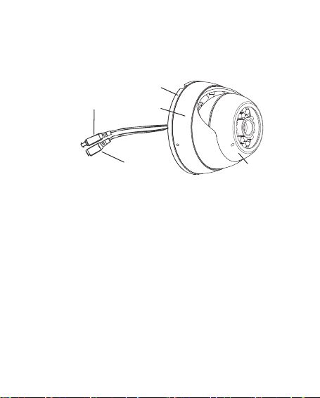
EN Figure 1: Parts of the camera
A. Video cable; B. Power cable; C. Mounting
bracket; D. Shroud; E. Camera
DE Abbildung 1: Teile der Kamera
A. Videokabel; B. Stromkabel;
C. Montagehalterung; D. Schutzabdeckung;
E. Kamera
ES Figura 1: Partes de la cámara
A. Cable de vídeo; B. Cable de
alimentación; C. Soporte de montaje;
D. Protección; E. Cámara
FR Figure 1 : Éléments de la caméra
A. Câble vidéo ; B. Câble d'alimentation ;
3
Page 6

g
y
j
C. Support de montage; D.Capot; E. Caméra
IT Figura 1: parti della telecamera
A. Cavo video; B. Cavo di alimentazione; C.
Supporto di montaggio; D. Rivestimento; E.
Telecamera
NL Afbeelding 1: Onderdelen van de camera
A. Videokabel; B. Voedingskabel;
C. Monta
PL Rysunek 1: elementy kamery
A. Przewód wideo; B. Kabel zasilania;
C. Uchw
PT Figura 1: Componentes da câmara
A. Cabo de vídeo; B. Cabo de alimentação;
C. Suporte de montagem; D. Cobertura; E.
Câmara
RU Рис. 1. Детали камеры
A. Видеокабель; B. Кабель питания;
C. Монтажный кронштейн; D. Кожух;
E. Камера
TR Şekil 1: Kameranın parçaları
A. Video kablosu; B. Güç kablosu;
C. Monta
esteun; D. Mantel; E. Camera
t mocujący; D. Osłona; E. Kamera
aparatı; D. Örtü; E. Kamera
4
Page 7
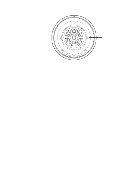
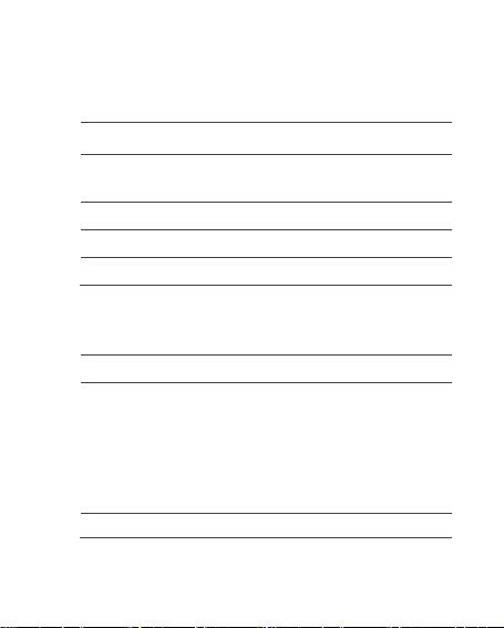
EN Figure 2: Camera front
A. LED IR lights; B. Lens; C. Light sensor
DE Abbildung 2: Vorderseite der Kamera
A. LED-IR-Leuchten; B. Objektiv;
C. Lichtsensor
ES Figura 2: Parte delantera de la cámara
A. Luces LED IR; B. Lente; C. Sensor de luz
FR Figure 2 : Avant de la caméra
A. Témoins lumineux LED IR ;
B. Objectif ; C. Capteur de luminosité
5
Page 8

IT Figura 2: parte anteriore della
telecamera
A. IR LED; B. Obiettivo; C. Sensore luce
NL Afbeelding 2: Voorkant camera
A. Infrarood LED's; B. Objectief;
C. Lichtsensor
PL Rysunek 2: przód kamery
A. Diody podczerwieni; B. Obiektyw;
C. Czujnik światła
PT Figura 2: Parte da frente da câmara
A. Luzes LED IV; B. Lente; C. Sensor
de luz
RU Рис. 2. Камера (вид спереди)
A. Инфракрасные светодиоды;
B. Объектив; C. Оптический датчик
TR Şekil 2: Kameranın önü
A. LED IR ışıklar; B. Lens; C. Işık sensörü
6
Page 9
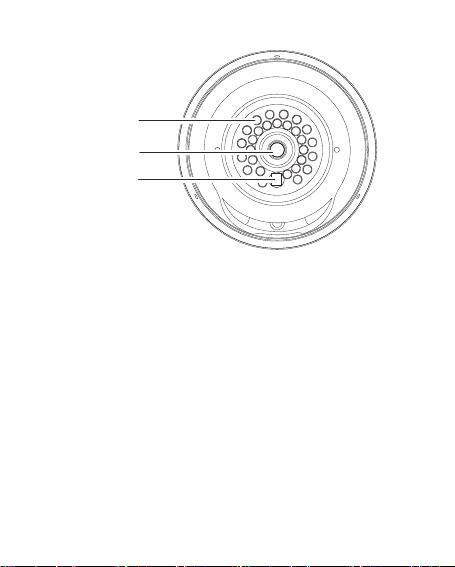
EN Figure 3: Camera zoom and focus
adjustment
A. Focus; B. Zoom
Note: Zoom and focus are only available
on the TVD-TIR6-MR(-P) and TVD-TIR6HR(-P) models.
DE Abbildung 3: Zoom- und
Fokuseinstellung der Kamera
A. Fokus; B. Zoom
Hinweis: Zoom und Fokus sind nur bei
den Modellen TVD-TIR6-MR(-P) und
TVD-TIR6-HR(-P) verfügbar.
7
Page 10

ES Figura 3: Ajuste del zoom y del
enfoque de la cámara
A. Enfoque; B. Zoom
Nota: el enfoque y el zoom solo están
disponibles en los modelos
TVD-TIR6-MR(-P) y TVD-TIR6-HR(-P).
FR Figure 3 : Réglage du zoom et de la
mise au point de la caméra
A. Mise au point ; B. Zoom
Remarque : Le zoom et la mise au point
ne sont disponibles que sur les modèles
TVD-TIR6-MR(-P) et TVD-TIR6-HR(-P).
IT Figura 3: regolazione dello zoom e
della messa a fuoco della telecamera
A. Messa a fuoco; B. Zoom
Nota: la messa a fuoco e lo zoom sono
disponibili solo sui modelli
TVD-TIR6-MR(-P) e TVD-TIR6-HR(-P).
NL Afbeelding 3: Camerzoomfunctie en
scherpstelling
A. Focus; B. Zoom
Opmerking: Zoomen en scherpstellen is
alleen mogelijk op de modellen
TVD-TIR6-MR(-P) en TVD-TIR6-HR(-P).
8
Page 11

PL Rysunek 3: regulacja powiększenia i
ostrości kamery
A. Ostrość; B. Powiększenie
Uwaga: regulacja powiększenia i ostrości
dostępna jest tylko w modelach
TVD-TIR6-MR(-P) i TVD-TIR6-HR(-P).
PT Figura 3: Ajuste do zoom e da focagem
da câmara
A. Focagem; B. Zoom
Nota: as funções de zoom e focagem só
estão disponíveis nos modelos
TVD-TIR6-MR(-P) e TVD-TIR6-HR(-P).
RU Рис. 3. Настройка масштаба и
фокуса камеры
A. Фокусировка; B. Масштабирование
Примечание. Фокусировка и
масштабирование доступны только на
моделях TVD-TIR6-MR(-P) и
TVD-TIR6-HR(-P).
TR Şekil 3: Kamera zoom ve fokus ayarı
A. Fokus; B. Zoom
Not: Zoom ve fokus, yalnızca
TVD-TIR6-MR(-P) ve TVD-TIR6-HR(-P)
modellerinde mevcuttur.
9
Page 12

EN
Overview
This is the TruVision IR Dome Camera Pocket
Guide for models TVD-TIR6-SR(-P), TVD-TIR6MR(-P) and TVD-TIR6-HR(-P). This pocket guide
describes a standard installation.
The camera consists of the following:
Camera with power and video output cables
Camera shroud
Mounting bracket
Mounting hardware
Hex wrench
Gang box adapter plate (for TVD-TIR6-MR(-P)
and TVD-TIR6-HR(-P) models only).
Rubber plug 4 pieces (for TVD-TIR6-MR(-P) and
TVD-TIR6-HR(-P) models only)
Refer to the figures on pages 3, 5 and 7 when
performing the camera setup procedures.
EN 10
Page 13

Installation
To install the camera:
1. Using the mounting bracket as a template,
place it level against the mounting surface and
mark the position of the mounting holes.
2. Following all local codes, drill and prepare the
mounting holes.
3. Route the camera’s cable through one of the
four openings in the mounting bracket, and
then install the mounting bracket with the four
provided screws. If your mounting surface
requires it, use the provided wall anchors or
other appropriate fasteners.
4. While holding the camera in place, set the
camera shroud over the camera.
Note: If you are installing on a gang box or routing
the wires through the wall, connect a 75 ohm
coaxial video cable to the camera’s video
cable, and connect a 12 VDC (TVD-TIR6-SR(P)) or 12 VDC/24 VAC (TVD-TIR6-MR/HR(-P))
power supply to the power cable.
5. Using the provided Hex wrench, lightly tighten
the three screws on the shroud. When lightly
tightened, the shroud holds the camera in place
and you can adjust the camera position.
11 EN
Page 14

6. Connect a 75 ohm coaxial video cable to the
camera’s video cable, and connect a 12 VDC
(TVD-TIR6-SR(-P)) or 12 VDC/24 VAC (TVDTIR6-MR/HR(-P)) power supply to the power
cable.
7. Check the picture and adjust the camera
position and angle as required.
Note: When installing a TVD-TIR6-MR(-P) or TVD-
TIR6-HR(-P) camera, tilting the camera
housing past 80° may result in reflection of IR
illumination from the camera base into the lens.
This can distort or obscure the picture in night
mode.
8. Tighten the shroud screws to secure it to the
mounting bracket. Ensure that the camera
shroud is firmly attached to the bracket.
9. If necessary, use a flat blade screwdriver to
adjust the zoom first, and then the focus (see
Figure 3 on page 7).
10. Put the rubber plug into the focus and zoom
holes to prevent water and moisture getting
inside.
EN 12
Page 15
Specifications
TVD-TIR6-SR(-P)
Power supply 12 VDC
Current 70 mA (IR Off)
Power consumption 2.28 W max.
Weight 0.86 lb. (390 g)
Dimensions (H × Ø) 2.7 x 3.7 (69 x 94 mm)
TVD-TIR6-MR(-P) and
TVD-TIR6-HR(-P)
Power supply 12 VDC
Current TVD-TIR6-MR(-P):
Power TVD-TIR6-MR(-P):
13 EN
190 mA (IR On)
140 mA (IR Off)
470 mA (IR On)
TVD-TIR6-HR(-P):
135 mA (IR OFF)
460 mA (IR ON)
Page 16

consumption 5.64 W max.
TVD-TIR6-HR(-P):
5.4 W max.
Weight 1.7 lb. (760 g)
Dimensions
(H × Ø)
Power supply 24 VAC
Current TVD-TIR6-MR(-P):
Power
consumption
Weight 1.7 lb. (760 g)
Dimensions
(H × Ø)
3.25 x 4.7
(82 x 119 mm)
157 mA (IR Off)
415 mA (IR On)
TVD-TIR6-HR(-P):
152 mA (IR OFF)
404 mA (IR ON)
TVD-TIR6-MR(-P):
5 W max.
TVD-TIR6-HR(-P):
4.8 W max.
3.25 x 4.7
(82 x 119 mm)
EN 14
Page 17

DE
Übersicht
Dies ist die Kurzanleitung für die TruVision IR
Dome-Kamera, Modelle TVD-TIR6-SR(-P), TVDTIR6-MR(-P) und TVD-TIR6-HR(-P). In dieser
Kurzanleitung wird die Standardinstallation
beschrieben.
Die Kamera umfasst folgende Elemente:
Kamera mit Netz- und Videoausgabekabeln
Kameraschutzabdeckung
Montagehalterung
Montageteile
Sechskantschlüssel
Gang-Box Adapterplatte Zoom (nur Modelle
TVD-TIR6-MR(-P) und
TVD-TIR6-HR(-P)).
Gummistopfen, 4 Stück (nur Modelle TVD-TIR6-
MR(-P) und TVD-TIR6-HR(-P))
Ziehen Sie bei der Einrichtung der Kamera die
Abbildungen auf den Seiten 3, 5 und 7 zurate.
15 DE
Page 18

Installation
Die Kamera montieren:
1. Platzieren Sie die Montagehalterung als
Vorlage waagerecht zur der Montagefläche.
Markieren Sie die Position der
Montageöffnungen.
2. Bohren Sie unter Beachtung der örtlichen
Bestimmungen die Montageöffnungen und
bereiten Sie diese vor.
3. Führen Sie das Kabel der Kamera durch eine
der vier Öffnungen in der Montagehalterung
und installieren Sie anschließend die
Montagehalterung mithilfe der vier
mitgelieferten Schrauben. Sollte es die
Montagefläche erfordern, verwenden Sie die
mitgelieferten Wandverankerungen oder
andere geeignete Befestigungselemente.
4. Halten Sie die Kamera in der richtigen Position
und bringen Sie dabei die
Kameraschutzabdeckung an.
Hinweis: Wenn Sie die Kamera auf der Gang-Box
installieren oder die Kabel durch die Wand
führen, schließen Sie ein koaxiales Videokabel
(75 Ohm) an das Videokabel der Kamera sowie
ein Netzteil mit
DE 16
Page 19

12 V DC (TVD-TIR6-SR(-P)) bzw.
12 V DC/24 V AC (TVD-TIR6-MR/HR(-P)) an
das Netzkabel an.
5. Ziehen Sie die drei Schrauben an der
Schutzabdeckung mithilfe des mitgelieferten
Inbusschlüssels leicht an. Sind diese leicht
angezogen, wird die Kamera durch die
Schutzabdeckung gehalten und Sie können die
Kameraposition einstellen.
6. Schließen Sie ein koaxiales Videokabel (75 Ohm) an
das Videokabel der Kamera sowie ein Netzteil mit
12 V DC (TVD-TIR6-SR(-P)) bzw. 12 V DC/24 V AC
(TVD-TIR6-MR/HR(-P)) an das Netzkabel an.
7. Überprüfen Sie das Bild und passen Sie
Position und Winkel der Kamera nach Bedarf
an.
Hinweis: Wenn Sie eines der Kameramodelle TVD-
TIR6-MR(-P) oder TVD-TIR6-HR(-P) installieren,
kann das Neigen des Kameragehäuses über 80°
hinaus zu Reflexionen der IR-Beleuchtung von
der Kamerabasis in das Objektiv führen. Dies
kann zur Verzerrung oder Verdunkelung des
Bildes im Nachtmodus führen.
8. Ziehen Sie die Schrauben an der
Schutzabdeckung fest, um diese an der
Montagehalterung zu fixieren. Vergewissern
17 DE
Page 20

Sie sich, dass die Kameraschutzabdeckung
fest in der Halterung sitzt.
9. Wenn erforderlich, verwenden Sie einen
Schlitzschraubendreher, um zuerst den Zoom
und dann den Fokus anzupassen (siehe
Abbildung 3 auf Seite 7).
10. Verschließen Sie die Öffnungen für Fokus und
Zoom mit den Gummistopfen, um das
Eindringen von Wasser oder Feuchtigkeit zu
verhindern.
Technische Daten
TVD-TIR6-SR(-P)
Netzteil 12 V DC
Stromaufnahme 70 mA (IR AUS)
Leistungsaufnahme Max. 2,28 W
Gewicht 390g
Abmessungen (H × Ø) 69 x 94 mm
DE 18
190 mA (IR EIN)
Page 21

TVD-TIR6-MR(-P) und
TVD-TIR6-HR(-P)
Netzteil 12 V DC
Stromaufnahme TVD-TIR6-MR(-P):
Leistungsaufnahme TVD-TIR6-MR(-P):
Gewicht 760 g
Abmessungen (H × Ø) 82 x 119 mm
19 DE
140 mA (IR AUS)
470 mA (IR EIN)
TVD-TIR6-HR(-P):
135 mA (IR AUS)
460 mA (IR EIN)
Max. 5,64 W
TVD-TIR6-HR(-P):
Max. 5,4 W
Page 22

Netzteil 24 V AC
Stromaufnahme TVD-TIR6-MR(-P):
Leistungsaufnahme TVD-TIR6-MR(-P):
Gewicht 760 g
Abmessungen (H × Ø) 82 x 119 mm
157 mA (IR AUS)
415 mA (IR EIN)
TVD-TIR6-HR(-P):
152 mA (IR AUS)
404 mA (IR EIN)
Max. 5 W
TVD-TIR6-HR(-P):
Max. 4,8 W
DE 20
Page 23

ES
Descripción general
Esta es la Guía de bolsillo de la cámara domo
TruVision IR de los modelos TVD-TIR6-SR (-P), TVDTIR6-MR(-P) y TVD-TIR6-HR(-P). Esta guía describe
una instalación estándar.
La cámara consta de los siguientes componentes:
Cámara con cables de alimentación y de salida
de vídeo
Protección de la cámara
Soporte de montaje
Material de montaje
Llave hexagonal
Placa adaptadora para caja (solo en los
modelos TVD-TIR6-MR(-P) y
TVD-TIR6-HR(-P)).
Conector de goma, 4 unidades (solo en los
modelos TVD-TIR6-MR(-P) y
TVD-TIR6-HR(-P)).
21 ES
Page 24

Consulte las siguientes figuras en las páginas 3, 5 y 7
para realizar los procedimientos de instalación de la
cámara.
Instalación
Para instalar la cámara:
1. Utilizando el soporte de montaje como plantilla,
colóquelo nivelado sobre la superficie de
montaje y marque la posición de los orificios de
montaje.
2. Siguiendo todas las normativas locales, taladre
y prepare los orificios de montaje.
3. Introduzca el cable de la cámara a través de
una de las cuatro aberturas del soporte de
montaje y después instálelo con los cuatro
tornillos incluidos. Si la superficie de montaje lo
requiere, utilice las sujeciones de pared u otras
sujeciones adecuadas.
4. Mientras sujeta la cámara, coloque la
protección de la cámara, cubriéndola.
Nota: si está instalando en la caja o pasando los cables
a través de la pared, conecte un cable coaxial de
vídeo de 75 ohmios al cable de vídeo de la
cámara y una fuente de alimentación de 12 V CC
ES 22
Page 25

(TVD-TIR6-SR(-P)) o de 12 V CC/24 V CA (TVDTIR6-MR/HR(-P)) al cable de alimentación.
5. Apriete levemente los tres tornillos de la
protección de la cámara con la llave hexagonal
incluida. Una vez fijada, la protección de la
cámara la mantiene en su lugar y ya puede
ajustar su posición.
6. Conecte un cable coaxial de vídeo de 75 ohmios
al cable de vídeo de la cámara y una fuente de
alimentación de 12 V CC (TVD-TIR6-SR(-P)) o
de 12 V CC/24 V CA (TVD-TIR6-MR/HR(-P)) al
cable de alimentación.
7. Compruebe la imagen y ajuste la posición y el
ángulo de la cámara.
Nota: al instalar una cámara TVD-TIR6-MR(-P) o
TVD-TIR6-HR(-P), si inclina la carcasa más de
80º, el reflejo de las luces IR de la base de la
cámara podría incidir sobre la lente. Esto
podría distorsionar u oscurecer la imagen en el
modo noche.
8. Apriete los tornillos de la protección de la
cámara para asegurarla al soporte de montaje.
Asegúrese de que la protección de la cámara
está firmemente sujeta al soporte.
23 ES
Page 26

9. Si fuera necesario, utilice un destornillador
plano para ajustar primero el zoom y luego el
enfoque (consulte la Figura 3 en la página 7).
10. Coloque el conector de goma en los orificios de
enfoque y zoom para impedir que entre agua y
humedad.
Especificaciones
TVD-TIR6-SR(-P)
Fuente de
alimentación
Corriente 70 mA (IR APAGADO)
Consumo de
energía
Peso 390 g
Dimensiones
(A x Ø)
ES 24
12 V CC
190 mA (IR ENCENDIDO)
2,28 W máx.
69 x 94 mm
(2,7 x 3,7 pulg.)
Page 27

TVD-TIR6-MR(-P) y
TVD-TIR6-HR(-P)
Fuente de
alimentación
Corriente TVD-TIR6-MR(-P):
Consumo de
energía
Peso 760 g
Dimensiones
(A x Ø)
25 ES
12 V CC
140 mA (IR APAGADO)
470 mA (IR ENCENDIDO)
TVD-TIR6-HR(-P):
135 mA (IR APAGADO)
460 mA (IR ENCENDIDO)
TVD-TIR6-MR(-P):
5,64 W máx.
TVD-TIR6-HR(-P):
5,4 W máx.
82 x 119 mm
(3,25 x 4,7 pulg.)
Page 28

Fuente de
alimentación
Corriente TVD-TIR6-MR(-P):
Consumo de
energía
Peso 760 g
Dimensiones
(A x Ø)
24 V CA
157 mA (IR APAGADO)
415 mA (IR ENCENDIDO)
TVD-TIR6-HR(-P):
152 mA (IR APAGADO)
404 mA (IR ENCENDIDO)
TVD-TIR6-MR(-P):
5 W máx.
TVD-TIR6-HR(-P):
4,8 W máx.
82 x 119 mm
(3,25 x 4,7 pulg.)
ES 26
Page 29

FR
Présentation
Ceci est le guide de poche de la caméra dôme IR pour
les modèles TVD-TIR6-SR(-P),
TVD-TIR6-MR(-P) et TVD-TIR6-HR(-P). Ce guide de
poche décrit une installation standard.
La caméra est composée des éléments suivants :
Caméra avec câble d'alimentation et de sortie
vidéo
Capot de la caméra
Support de montage
Matériel de fixation
Clé Allen
Plaque d'adaptation pour la boîte de jonction
(modèles TVD-TIR6-MR(-P) et TVD-TIR6-HR(P) uniquement).
Bouchon en caoutchouc 4 pièces (modèles
TVD-TIR6-MR(-P) et TVD-TIR6-HR(-P)
uniquement)
Consultez les figures des pages 3, 5 et 7 lors de
l'installation de la caméra.
27 FR
Page 30

Installation
Pour installer la caméra :
1. Utilisez le support de fixation comme modèle et
placez-le droit contre la surface de montage,
puis marquez la position des orifices de
montage.
2. En respectant la réglementation locale, percez
et préparez les orifices de montage.
3. Faites passer le câble de la caméra dans l'une
des quatre ouvertures du support de fixation,
puis installez le support de fixation à l'aide des
quatre vis fournies. En fonction de la surface
de montage, utilisez les attaches murales
fournies ou toute autre attache nécessaire.
4. Tout en maintenant la caméra en place, placez
le capot de la caméra sur celle-ci.
Remarque : Si vous effectuez l'installation sur une
boîte de jonction ou si vous faites passer les fils
dans le mur, connectez un câble vidéo coaxial
75 ohm au câble vidéo de la caméra et reliez
une alimentation 12 V c.c. (TVD-TIR6-SR(-P)) ou
12 V c.c./24 V c.a. (TVD-TIR6-MR/HR(-P)) au
câble d'alimentation.
5. A l'aide de la clé Allen fournie, serrez
légèrement les trois vis du capot. Avec un
FR 28
Page 31

serrage minimal, le capot maintient la caméra
en place et vous pouvez régler la position de la
caméra.
6. Connectez un câble vidéo coaxial 75 ohm au câble
vidéo de la caméra et reliez une alimentation 12 V
c.c. (TVD-TIR6-SR(-P)) ou 12 V c.c./24 V c.a.
(TVD-TIR6-MR/HR(-P)) au câble d'alimentation.
7. Vérifiez l'image et réglez la position et l'angle
de la caméra si nécessaire.
Remarque : Lors de l'installation d'une caméra TVD-
TIR6-MR(-P) ou TVD-TIR6-HR(-P), l'inclinaison du
boîtier de la caméra au-delà de 80° peut entraîner
la réflexion de l'illumination IR de la base de la
caméra dans l'objectif. Ceci peut déformer ou
obscurcir l'image en mode nocturne.
8. Serrez les vis du capot pour le fixer au support
de fixation. Assurez-vous que le capot de la
caméra est fermement fixé au support.
9. Si nécessaire, utilisez un tournevis à lame plate
pour régler d'abord le zoom, puis réglez la mise
au point (voir la Figure 3 à la page 7).
10. Placez les bouchons en caoutchouc dans les
trous de la mise au point et du zoom pour
éviter la pénétration de l'eau et de l'humidité.
29 FR
Page 32

Spécifications
TVD-TIR6-SR(-P)
Alimentation
électrique
Courant 70 mA (IR DESACTIVE)
Consommation 2,28 W max.
Poids 390 g
Dimensions (H × Ø) 69 x 94 mm
TVD-TIR6-MR(-P) et
TVD-TIR6-HR(-P)
Alimentation
électrique
FR 30
12 V c.c.
190 mA (IR ACTIVE)
12 V c.c.
Page 33

Courant TVD-TIR6-MR(-P) :
Consommation TVD-TIR6-MR(-P) :
Poids 760 g
Dimensions (H × Ø) 82 x 119 mm
Alimentation
électrique
Courant TVD-TIR6-MR(-P) :
Consommation TVD-TIR6-MR(-P) :
140 mA (IR DÉSACTIVÉ)
470 mA (IR ACTIVÉ)
TVD-TIR6-HR(-P) :
135 mA (IR DÉSACTIVÉ)
460 mA (IR ACTIVÉ)
5,64 W max.
TVD-TIR6-HR(-P) :
5,4 W max.
24 V c.a.
157 mA (IR DESACTIVE)
415 mA (IR ACTIVE)
TVD-TIR6-HR(-P) :
152 mA (IR DÉSACTIVÉ)
404 mA (IR ACTIVÉ)
31 FR
Page 34

5 W max.
TVD-TIR6-HR(-P) :
4,8 W max.
Poids 760 g
Dimensions (H × Ø) 82 x 119 mm
FR 32
Page 35

IT
Panoramica
La presente è la guida rapida della telecamera
TruVision IR Dome per i modelli TVD-TIR6-SR(-P),
TVD-TIR6-MR(-P) e TVD-TIR6-HR(-P), in cui viene
descritta l'installazione standard.
La telecamera è formata dai seguenti componenti:
Telecamera con cavi di uscita video e
alimentazione
Rivestimento della telecamera
Supporto di montaggio
Elementi di fissaggio
Chiave esagonale
Piastra adattatrice per scatola a foro singolo
(solo per i modelli
TVD-TIR6-MR(-P) e TVD-TIR6-HR(-P)).
Tappi in gomma - 4 pezzi (solo per i modelli
TVD-TIR6-MR(-P) e
TVD-TIR6-HR(-P))
Durante le procedure di installazione, fare
riferimento alle figure alle pagine 3, 5 e 7.
33 IT
Page 36

Installazione
Installazione della telecamera:
1. Utilizzando il supporto di montaggio come
modello, posizionarlo contro la superficie di
montaggio e contrassegnare la posizione dei
fori di montaggio.
2. Praticare i fori di montaggio conformemente
alle normative locali.
3. Far passare il cavo della telecamera attraverso
una delle quattro aperture nel supporto di
montaggio, quindi installare il supporto
utilizzando le quattro viti fornite. Se la
superficie di montaggio lo richiede, utilizzare i
tasselli da parete forniti o altri dispositivi di
fissaggio adeguati.
4. Tenendo in posizione la telecamera, installare il
rivestimento sopra di essa.
Nota: se si effettua l'installazione sulla scatola a
foro singolo o si fanno passare i cavi nella
parete, collegare un cavo video coassiale da
75 ohm al cavo video della telecamera e
collegare un alimentatore da 12 Vcc (TVDTIR6-SR(-P)) o 12 Vcc/24 Vca (TVD-TIR6MR/HR(-P)) al cavo di alimentazione.
IT 34
Page 37

5. Utilizzando la chiave esagonale fornita, serrare
leggermente le tre viti sul rivestimento. Una
volta serrate leggermente le viti, il rivestimento
mantiene ferma la telecamera ed è possibile
regolarne la posizione.
6. Collegare un cavo video coassiale da 75 ohm al cavo
video della telecamera e collegare un alimentatore da
12 Vcc (TVD-TIR6-SR(-P)) o 12 Vcc/24 Vca (TVDTIR6-MR/HR(-P)) al cavo di alimentazione.
7. Verificare l'immagine e regolare la posizione e
l'angolatura della telecamera secondo
necessità.
Nota: quando si installa una telecamera modello TVD-
TIR6-MR(-P) o TVD-TIR6-HR(-P), l'inclinazione
della custodia della telecamera di oltre 80° può
avere come risultato un riflesso dell'illuminazione IR
dalla base della telecamera sull'obiettivo. Ciò può
distorcere o oscurare l'immagine in modalità notte.
8. Serrare le viti del rivestimento per fissarlo al
supporto di montaggio. Accertarsi che sia
saldamente fissato al supporto.
9. Se necessario, utilizzare un cacciavite a punta
piatta per regolare prima lo zoom e quindi la
messa a fuoco (vedere la Figura 3 a pagina 7).
35 IT
Page 38

10. Inserire i tappi in gomma nei fori della messa a
fuoco e dello zoom per evitare l'ingresso di
acqua e umidità all'interno della telecamera.
Specifiche tecniche
TVD-TIR6-SR(-P)
Alimentazione 12 Vcc
Corrente 70 mA (IR SPENTO)
Consumo 2,28 W (max)
Peso 390 g
Dimensioni
(A × Ø)
IT 36
190 mA (IR ACCESO)
69 x 94 mm
Page 39

TVD-TIR6-MR(-P) e
TVD-TIR6-HR(-P)
Alimentazione 12 Vcc
Corrente TVD-TIR6-MR(-P):
Consumo TVD-TIR6-MR(-P):
Peso 760 g
Dimensioni
(A × Ø)
37 IT
140 mA (IR SPENTO)
470 mA (IR ACCESO)
TVD-TIR6-HR(-P):
135 mA (IR SPENTO)
460 mA (IR ACCESO)
5,64 W (max)
TVD-TIR6-HR(-P):
5,4 W (max)
82 x 119 mm
Page 40

Alimentazione 24 Vca
Corrente TVD-TIR6-MR(-P):
Consumo TVD-TIR6-MR(-P):
Peso 760 g
Dimensioni
(A × Ø)
157 mA (IR SPENTO)
415 mA (IR ACCESO)
TVD-TIR6-HR(-P):
152 mA (IR SPENTO)
404 mA (IR ACCESO)
5 W (max)
TVD-TIR6-HR(-P):
4,8 W (max)
82 x 119 mm
IT 38
Page 41

NL
Overzicht
Dit is de TruVision IR Dome Camera Beknopte
handleiding voor de modellen
TVD-TIR6-SR(-P), TVD-TIR6-MR(-P) en TVD-TIR6HR(-P). In deze beknopte handleiding wordt een
standaardinstallatie beschreven.
De Camera bestaat uit de volgende onderdelen:
Camera met voedings- en video-
uitgangskabels
Cameramantel
Montagebeugel
Bevestigingsmateriaal
Inbussleutel
Adapterplaat voor aansluitkast (alleen voor de
modellen TVD-TIR6-MR(-P) en TVD-TIR6-HR(P)).
Rubberen plug 4 stuks (alleen voor de
modellen TVD-TIR6-MR(-P) en TVD-TIR6-HR(P)).
39 NL
Page 42

Raadpleeg de afbeeldingen op pagina's 3, 5 en 7
tijdens het uitvoeren van de installatieprocedures
voor de camera.
Installatie
U installeert de camera als volgt:
1. Gebruik de montagebeugel als sjabloon, plaats
deze waterpas tegen het montageoppervlak en
markeer de positie van de bevestigingsgaten.
2. Boor en prepareer volgens alle plaatselijke
voorschriften de bevestigingsgaten.
3. Voer de kabel van de camera door een van de
vier openingen in de montagebeugel en
installeer vervolgens de montagebeugel met de
vier bijgeleverde schroeven. Indien uw
montageoppervlak dat vereist, maakt u gebruik
van meegeleverde muurverankeringen of
andere geschikte bevestigingsmaterialen.
4. Terwijl u de camera op zijn plek houdt, plaatst
u de cameramantel op de camera.
Opmerking: Als u de installatie verricht op een
aansluitkast of de draden door de muur leidt, sluit
u een 75 ohm coaxiale videokabel aan op de
videokabel van de camera en sluit u een 12 VDC
NL 40
Page 43

(TVD-TIR6-SR(-P)) of 12 VDC/24 VAC (TVDTIR6-MR/HR(-P)) voeding aan op de
voedingskabel.
5. Draai de drie schroeven op de mantel lichtjes
vast met de bijgeleverde inbussleutel. Nadat de
schroeven lichtjes zijn vastgezet, houdt de
mantel de camera op zijn plaats en kunt u de
camerapositie aanpassen.
6. Sluit een 75 ohm coaxiale videokabel aan op
de videokabel van de camera en sluit u een 12
VDC (TVD-TIR6-SR(-P)) of 12 VDC/24 VAC
(TVD-TIR6-MR/HR(-P)) voeding aan op de
voedingskabel.
7. Controleer het beeld en pas de camerapositie
en beeldhoek aan naar wens.
Opmerking: Als u tijdens het installeren van een
TVD-TIR6-MR(-P) of TVD-TIR6-HR(-P)-camera
de behuizing van de camera verder dan 80°
draait, kan dit resulteren in weerspiegeling van
de infraroodverlichting op de voet van de
camera in de lens. Hierdoor kan het beeld in de
nachtmodus worden vervormd of donker
worden.
8. Draai de schroeven vast om de mantel vast te
zetten aan de bevestigingsbeugel. Controleer
of de cameramantel stevig vastzit aan de
beugel.
41 NL
Page 44

9. Gebruik eventueel een schroevendraaier met
een platte kop om eerst de zoomstand en
vervolgens de scherpstelling in te stellen (zie
Afbeelding 3 op pagina 7).
10. Plaats de rubberen plug in de focus- en
zoomopeningen om te voorkomen dat water en
vocht kan binnendringen.
Specificaties
TVD-TIR6-SR(-P)
Voedingseenheid 12 VDC
Spanning 70 mA (IR UIT)
Stroomverbruik 2,28 W max.
Gewicht 390 g (0,86 lb)
Afmetingen
(H × Ø)
NL 42
190 mA (IR AAN)
69 x 94 mm
(2,7 x 3,7 inch)
Page 45

TVD-TIR6-MR(-P) en
TVD-TIR6-HR(-P)
Voedingseenheid 12 VDC
Spanning TVD-TIR6-MR(-P):
Stroomverbruik TVD-TIR6-MR(-P):
Gewicht 760 g (1,7 lb)
Afmetingen
(H × Ø)
43 NL
140 mA (IR UIT)
470 mA (IR AAN)
TVD-TIR6-HR(-P):
135 mA (IR UIT)
460 mA (IR AAN)
5,64 W max.
TVD-TIR6-HR(-P):
5,4 W max.
82 x 119 mm
(3,25 x 4,7 inch)
Page 46

Voedingseenheid 24 VAC
Spanning TVD-TIR6-MR(-P):
Stroomverbruik TVD-TIR6-MR(-P):
Gewicht 760 g (1,7 lb)
Afmetingen
(H × Ø)
157 mA (IR UIT)
415 mA (IR AAN)
TVD-TIR6-HR(-P):
152 mA (IR UIT)
404 mA (IR AAN)
5 W max.
TVD-TIR6-HR(-P):
4,8 W max.
82 x 119 mm
(3,25 x 4,7 inch)
NL 44
Page 47

PL
Informacje podstawowe
Niniejszy dokument to kieszonkowy przewodnik dla
modeli TVD-TIR6-SR(-P), TVD-TIR6-MR(-P) i TVDTIR6-HR(-P) kamery kopułowej TruVision IR.
Niniejszy kieszonkowy przewodnik opisuje
procedurę standardowej instalacji.
W opakowaniu kamery znajdują się następujące
elementy:
Kamera z przewodem zasilającym i przewodem
wyjścia wideo
Osłona kamery
Uchwyt mocujący
Elementy mocujące
Klucz imbusowy
Płyta montażowa puszki połączeniowej (tylko w
przypadku modeli TVD-TIR6-MR(-P) i TVDTIR6-HR(-P)).
4 zatyczki gumowe (tylko w przypadku modeli
TVD-TIR6-MR(-P) i TVD-TIR6-HR(-P)).
45 PL
Page 48

Aby przeprowadzić konfigurację kamery, zapoznaj
się z rysunkami na stronach 3, 5 i 7.
Instalacja
Aby zainstalować kamerę:
1. Korzystając z uchwytu mocującego jako wzoru,
umieść go poziomo przy powierzchni
montażowej i zaznacz pozycję otworów
montażowych.
2. Zgodnie z lokalnymi przepisami wywierć i
przygotuj otwory montażowe.
3. Poprowadź przewody kamery przez jeden z
czterech otworów w uchwycie montażowym, a
następnie przymocuj uchwyt montażowy przy
pomocy czterech dołączonych śrub. W
zależności od powierzchnia montażowej, użyj
dołączone kołki rozporowe lub inne
odpowiednie wkręty.
4. Przytrzymując kamerę w miejscu montażu,
nałóż osłonę kamery.
Uwaga: W przypadku montażu puszki
połączeniowej lub prowadzenia kabli przez
ścianę, podłącz 75 omowy koncentryczny kabel
PL 46
Page 49

wideo do przewodu wideo kamery oraz źródło
zasilania prądem stałym 12 V (TVD-TIR6-SR(P)) lub prądem stałym 12 V / zmiennym 24 V
(TVD-TIR6-MR/HR(-P)) do przewodu zasilania.
5. Za pomocą dołączonego klucza imbusowego
delikatnie dokręć trzy śruby znajdujące się na
osłonie. Po delikatnym dokręceniu osłony,
przytrzymuje ona kamerę, co umożliwia
regulację jej położenia.
6. Podłącz 75 omowy koncentryczny kabel wideo
do przewodu wideo kamery oraz źródło
zasilania prądem stałym 12 V (TVD-TIR6-SR(P)) lub prądem stałym 12 V / zmiennym 24 V
(TVD-TIR6-MR/HR(-P)) do przewodu zasilania.
7. Sprawdź obraz oraz, jeśli to konieczne,
dopasuj położenie oraz kąt ustawienia kamery.
Uwaga: Przechylenie obudowy kamery pod kątem
ponad 80° podczas instalacji kamery TVD-TIR6MR(-P) lub TVD-TIR6-HR(-P) może spowodować
odbicia oświetlenia podczerwieni od podstawy
kamery do obiektywu. Może to spowodować
zniekształcenie lub zaciemnienie obrazu w trybie
nocnym.
47 PL
Page 50

8. Dokręć śruby osłony aby przymocować ją do
uchwytu montażowego. Sprawdź, czy obudowa
kamery jest mocno przymocowana do uchwytu.
9. Jeżeli to konieczne, za pomocą płaskiego
śrubokręta dokonaj najpierw regulacji
powiększenia, a następnie ostrości (zobacz
rysunek 3 na stronie 7).
10. Włóż zatyczki gumowe w otwory regulacji
powiększenia i ostrości, aby zabezpieczyć
kamerę przed dostaniem się do środka wilgoci.
Dane techniczne
TVD-TIR6-SR(-P)
Zasilacz 12 V, prąd stały
Natężenie 70 mA (oświetlenie podczerwieni
Zużycie
energii
Waga 390 g
PL 48
WYŁĄCZONE)
190 mA (oświetlenie podczerwieni
WŁĄCZONE)
Maks. 2,28 W
Page 51

Wymiary
(W × Ø)
69 x 94 mm
TVD-TIR6-MR(-P) i
TVD-TIR6-HR(-P)
Zasilacz 12 V, prąd stały
Natężenie TVD-TIR6-MR(-P):
Zużycie
energii
Waga 760 g
49 PL
140 mA (oświetlenie podczerwieni
WYŁĄCZONE)
470 mA (oświetlenie podczerwieni
WŁĄCZONE)
TVD-TIR6-HR(-P):
135 mA (oświetlenie podczerwieni
WYŁĄCZONE)
460 mA (oświetlenie podczerwieni
WŁĄCZONE)
TVD-TIR6-MR(-P):
Maks. 5,64 W
TVD-TIR6-HR(-P):
Maks. 5,4 W
Page 52

Wymiary
(W × Ø)
Zasilacz 24 V, prądu zmiennego
Natężenie TVD-TIR6-MR(-P):
Zużycie
energii
Waga 760 g
Wymiary
(W × Ø)
82 x 119 mm
157 mA (oświetlenie podczerwieni
WYŁĄCZONE)
415 mA (oświetlenie podczerwieni
WŁĄCZONE)
TVD-TIR6-HR(-P):
152 mA (oświetlenie podczerwieni
WYŁĄCZONE)
404 mA (oświetlenie podczerwieni
WŁĄCZONE)
TVD-TIR6-MR(-P):
Maks. 5 W
TVD-TIR6-HR(-P):
Maks. 4,8 W
82 x 119 mm
PL 50
Page 53

PT
Descrição geral
Este é o Guia Rápido da Câmara TruVision IR Dome,
modelos TVD-TIR6-SR(-P),
TVD-TIR6-MR(-P) e TVD-TIR6-HR(-P). Este guia
rápido descreve uma instalação standard.
A Câmara inclui os seguintes elementos:
Câmara com cabos de alimentação e saída de
vídeo
Cobertura da câmara
Suporte de montagem
Hardware de instalação
Chave sextavada
Placa adaptadora da caixa de distribuição (só
modelos TVD-TIR6-MR(-P) e
TVD-TIR6-HR(-P)).
Bujão de borracha, 4 peças (só modelos TVD-
TIR6-MR(-P) e TVD-TIR6-HR(-P)).
Consulte as figuras nas páginas 3, 5 e 7 ao realizar
procedimentos de configuração da câmara.
51 PT
Page 54

Instalação
Para instalar a câmara:
1. Utilizando o suporte de montagem como
modelo, coloque-o nivelado na superfície de
montagem e marque a posição dos orifícios de
montagem.
2. Cumprindo todos os códigos locais, abra e
prepare os orifícios de montagem.
3. Passe o cabo da câmara por uma das quatro
aberturas do suporte de montagem e, a seguir,
instale o suporte de montagem com os quatro
parafusos fornecidos. Se a superfície de
montagem assim o exigir, utilize as buchas de
parede ou outros elementos de fixação
fornecidos.
4. Segurando na câmara, coloque a respectiva
cobertura sobre a câmara.
Nota: se estiver a efectuar a instalação nnuma
caixa de distribuição ou a passar os cabos pela
parede, ligue um cabo de vídeo coaxial de 75
ohm ao cabo de vídeo da câmara e ligue uma
fonte de alimentação de 12 VDC (TVD-TIR6SR(-P)) ou 12 VDC/24 VAC (TVD-TIR6MR/HR(-P)) ao cabo de alimentação.
PT 52
Page 55

5. Com a chave sextavada fornecida, aperte
ligeiramente os três parafusos na cobertura.
Quando apertada sem força excessiva, a
cobertura mantém a câmara no lugar,
permitindo ao utilizador ajustar a posição da
mesma.
6. Ligue um cabo de vídeo coaxial de 75 ohm ao
cabo de vídeo da câmara e ligue uma fonte de
alimentação de 12 VDC (TVD-TIR6-SR(-P)) ou
12 VDC/24 VAC (TVD-TIR6-MR/HR(-P)) ao
cabo de alimentação.
7. Verifique a imagem e regule a posição e o
ângulo da câmara, conforme necessário.
Nota: ao instalar uma câmara TVD-TIR6-MR(-P) ou
TVD-TIR6-HR(-P), inclinar a caixa da câmara
mais de 80° pode resultar na reflexão da
iluminação IV da base da câmara para dentro
da lente. Isto pode distorcer ou obscurecer a
imagem no modo noite.
8. Aperte os parafusos da cobertura para fixá-la
ao suporte de montagem. Certifique-se de que
a cobertura da câmara está firmemente afixada
ao suporte.
9. Se necessário, utilize uma chave de parafusos
de lâmina chata para regular primeiro o zoom e
depois a focagem (consulte a Figura 3 na
página 7).
53 PT
Page 56

10. Coloque o bujão de borracha nos orifícios de
focagem e de zoom para impedir a entrada de
água e humidade.
Especificações
TVD-TIR6-SR(-P)
Fonte de
alimentação
Corrente 70 mA (IV DESLIGADO)
Consumo de
energia
Peso 390 g (0,86 lb)
Dimensões
(A × Ø)
PT 54
12 VDC
190 mA (IV LIGADO)
2,28 W máx.
69 x 94 mm (2,7 x 3,7 pol)
Page 57

TVD-TIR6-MR(-P) e
TVD-TIR6-HR(-P)
Fonte de
alimentação
Corrente TVD-TIR6-MR(-P):
Consumo de
energia
Peso 760 g (1,7 lb)
Dimensões
(A × Ø)
55 PT
12 VDC
140 mA (IR DESLIGADO)
470 mA (IR LIGADO)
TVD-TIR6-MR(-P):
135 mA (IR DESLIGADO)
460 mA (IR LIGADO)
TVD-TIR6-MR(-P):
5,64 W máx.
TVD-TIR6-HR(-P):
5,4 W máx.
82 x 119 mm
(3,25 x 4,7 pol)
Page 58

Fonte de
alimentação
Corrente TVD-TIR6-MR(-P):
Consumo de
energia
Peso 760 g (1,7 lb)
Dimensões
(A × Ø)
24 VCA
157 mA (IR DESLIGADO)
415 mA (IR LIGADO)
TVD-TIR6-MR(-P):
152 mA (IR DESLIGADO)
404 mA (IR LIGADO)
TVD-TIR6-MR(-P):
5 W máx.
TVD-TIR6-HR(-P):
4,8 W máx.
82 x 119 mm
(3,25 x 4,7 pol)
PT 56
Page 59

RU
Обзор
Этот документ представляет собой карманное
руководство купольной камеры TruVision IR для
моделей TVD-TIR6-SR(-P), TVD-TIR6-MR(-P) и
TVD-TIR6-HR(-P). В данном карманном
руководстве описана стандартная установка.
Камера состоит из перечисленных ниже
компонентов.
Камера с кабелями питания и видеовыхода
Кожух камеры
Монтажный кронштейн
Элементы крепления
Торцевой гаечный ключ
Соединительная плата для установочной
коробки (
P) и
TVD-TIR6-HR(-P)).
Резиновая пробка, 4 штуки, (только для
моделей TVD-TIR6-MR(-P) и
TVD-TIR6-HR(-P)).
57 RU
только для моделей TVD-TIR6-MR(-
Page 60

Для установки камеры используйте рисунки,
приведенные на стр. 3, 5 и 7.
Установка
Установка камеры.
1. Используя монтажный кронштейн в качестве
шаблона, поместите камеру на уровне
монтажной поверхности и отметьте места,
где должны быть расположены крепежные
отверстия.
2. Соблюдая местные нормативы,
просверлите и подготовьте крепежные
отверстия.
3. Проденьте кабель камеры сквозь одно из
четырех отверстий монтажного кронштейна.
Затем прикрутите кронштейн с помощью
четырех шурупов, входящих
поставки. При необходимости
воспользуйтесь стеновыми анкерами,
входящими в комплект поставки, или
любыми другими доступными элементами
крепления.
4. После установки камеры наденьте на нее
защитный кожух.
RU 58
в комплект
Page 61

Примечание. Если камера монтируется на
установочную коробку или кабели проходят
сквозь стену, подсоедините коаксиальный
видеокабель (на 75 Ом) к видеокабелю
камеры, а источник питания (на 12 В
постоянного тока для модели VD-TIR6-SR(P) или 12 В постоянного тока/24 В
переменного тока для модели TVD-TIR6-
MR/HR(-P)) к кабелю питания.
5. Слегка закрутите три шурупа с помощью
торцевого гаечного
камера остается на своем месте и ее
положение легко регулируется.
6. Подсоедините коаксиальный видеокабель (на
75 Ом) к видеокабелю камеры, а источник
питания (на 12 В постоянного тока для
модели VD-TIR6-SR(-P) или 12 В постоянного
тока/24 В переменного тока для модели
TVD-TIR6-MR/HR(-P)) к кабелю питания.
7. Проверьте изображение. При
необходимости выберите нужное
камеры и требуемый угол обзора.
Примечание. При установке модели TVD-TIR6-
MR(-P) или TVD-TIR6-HR(-P) поворот
корпуса камеры более, чем на 80°, может
привести к отражению инфракрасного
излучения от основания камеры на
ключа. В этом случае
положение
59 RU
Page 62

объектив. Это может стать причиной
искажения или затемнения изображения при
работе камеры в режиме ночной съемки.
8. Закрутите шурупы до конца, чтобы
закрепить защитный кожух на монтажном
кронштейне. Убедитесь в том, что защитный
кожух надежно закреплен на кронштейне.
9. При необходимости воспользуйтесь
отверткой с плоским лезвием, чтобы
сначала настроить масштаб, а затем
(см. рис. 3 на стр. 7).
10. Вставьте резиновую пробку в отверстия
фокусировки и масштабирования, чтобы
предотвратить попадание воды и влаги
внутрь устройства.
фокус
RU 60
Page 63

Характеристики
TVD-TIR6-SR(-P)
Источник
питания
Ток 70 мА (инфракрасные
Потребляемая
мощность
Вес 390 г (0,86 дюйма)
Габариты
(В × Ø)
61 RU
12 В постоянного тока
светодиоды выключены)
190 мА (инфракрасные
светодиоды включены)
2,28 Вт (макс.)
69 x 94 мм
(2,7 x 3,7 дюйма)
Page 64

TVD-TIR6-MR(-P) и
TVD-TIR6-HR(-P)
Источник
питания
Ток TVD-TIR6-MR(-P):
Потребляемая
мощность
Вес 760 г (1,7 фунта)
Габариты
(В × Ø)
RU 62
12 В постоянного тока
140 мА (инфракрасные
светодиоды выключены)
470 мА (инфракрасные
светодиоды включены)
TVD-TIR6-HR(-P):
135 мА (инфракрасные
светодиоды выключены)
460 мА (инфракрасные
светодиоды включены)
TVD-TIR6-MR(-P):
5,64 Вт (макс.)
TVD-TIR6-HR(-P):
5,4 Вт (макс.)
82 x 119 мм
(3,25 x 4,7 дюйма)
Page 65

Источник
питания
Ток TVD-TIR6-MR(-P):
Потребляемая
мощность
Вес 760 г (1,7 фунта)
Габариты
(В × Ø)
24 В перем. тока
157 мА (инфракрасные
светодиоды выключены)
415 мА (инфракрасные
светодиоды включены)
TVD-TIR6-HR(-P):
152 мА (инфракрасные
светодиоды выключены)
404 мА (инфракрасные
светодиоды включены)
TVD-TIR6-MR(-P):
5 Вт (макс.)
TVD-TIR6-HR(-P):
4,8 Вт (макс.)
82 x 119 мм
(3,25 x 4,7 дюйма)
63 RU
Page 66

TR
Genel Bakış
Bu, TVD-TIR6-SR(-P), TVD-TIR6-MR(-P) ve TVDTIR6-HR(-P) modelleri için, TruVision IR Dome
Kamera Cep Kılavuzudur. Bu cep kılavuzu standart
kurulumu anlatmaktadır.
Kamera şunlardan oluşur:
Güç ve video çıkış kablolu kamera
Kamera kılıfı
Montaj aparatı
Montaj donanımı
Altıgen anahtar
Gang box adaptör plakası (yalnızca
TVD-TIR6-MR(-P) ve TVD-TIR6-HR(-P)
modelleri için).
Kauçık priz 4 parça (yalnızca TVD-TIR6-MR(-P) ve
TVD-TIR6-HR(-P) modelleri için).
Kamera ayar prosedürlerini gerçekleştirirken, 3. 5.
ve 7. sayfadaki resimlere bakın.
TR 64
Page 67

Kurulum
Kamerayı kurmak için:
1. Montaj braketini şablon olarak kullanarak,
braketi montaj yüzeyine karşı aynı seviyeye
yerleştirin ve montaj deliklerinin konumunu
işaretleyin.
2. Tüm yerel kodları takip ederek, matkapla delin
ve montaj deliklerini hazırlayın.
3. Kamera kablosunu, montaj braketinin dört
açıklığından birinden geçirin ve sonra montaj
braketini verilen dört vida ile takın. Montaj
yüzeyiniz için gerekiyorsa, verilen duvar
kancalarını veya başka uygun bağlantı
elemanlarını kullanın.
4. Kamerayı yerinde tutarken, kamera kılıfını
kameranın üzerine yerleştirin.
Not: Gang box'ı monte ediyor veya kabloları
duvardan geçiriyorsanız, kameranın video
kablosuna 75 ohm'lik bir koaksiyel video
kablosu ve güç kablosuna da 12 VDC (TVDTIR6-SR(-P)) veya 12 VDC/24 VAC (TVDTIR6-MR/HR(-P)) güç kaynağı bağlayın.
5. Verilen Altıgen anahtar ile, kılıf üzerindeki üç
65 TR
hafifçe sıkın. Az sıkıldıkları zaman, kılıf
vidayı
Page 68

kamerayı yerinde tutar ve kameranın
konumunu ayarlayabilir.
6. Kameranın video kablosuna 75 ohm'lik bir
koaksiyel video kablosu ve güç kablosuna da 12
VDC (TVD-TIR6-SR(-P)) veya 12 VDC/24 VAC
(TVD-TIR6-MR/HR(-P)) güç kaynağı bağlayın.
7. Resmi kontrol edin ve kameranın konumunu ve
açısını istenen şekilde ayarlayın.
Not: Bir TVD-TIR6-MR(-P) veya TVD-TIR6-HR(-P)
kamera kurarken, kamera muhafazasını 80°'yi
geçecek şekilde eğmek, kamera tabanından
lensin içine giden IR aydınlatmasının
yansımasına neden olabilir. Bu görüntüyü gece
modunda bozabilir ve karartabilir.
8. Montaj braketine sabitlemek için kılıf vidalarını
sıkın. Kamera kılıfının brakete sıkıca takılmış
olduğundan emin olun.
9. Gerekirse, önce zoomu ayarlamak için düz uçlu bir
tornavida kullanın, sonra fokusu ayarlayın (Bkz. 7.
sayfadaki Şekil 3).
10. Suyun ve nemin içine girmemesi için, kauçuk
prizi fokus ve zoom deliklerine yerleştirin.
TR 66
Page 69

Teknik özellikler
TVD-TIR6-SR(-P)
Güç kaynağı 12 VDC
Akım 70 mA (IR KAPALI)
Güç tüketimi 2,28 W maks.
Ağırlık 0,86 lb.
Boyutlar
(Y × Ø)
TVD-TIR6-MR(-P) ve
TVD-TIR6-HR(-P)
Güç kaynağı 12 VDC
Akım TVD-TIR6-MR(-P):
Güç tüketimi TVD-TIR6-MR(-P):
67 TR
190 mA (IR AÇIK)
2,7 x 3,7 (69 x 94 mm)
140 mA (IR KAPALI)
470 mA (IR AÇIK)
TVD-TIR6-HR(-P):
135 mA (IR KAPALI)
460 mA (IR AÇIK)
Page 70

5,64 W maks.
TVD-TIR6-HR(-P):
5,4 W maks.
Ağırlık 1,7 lb.
Boyutlar
(Y × Ø)
Güç kaynağı 24 VAC
Akım TVD-TIR6-MR(-P):
Güç tüketimi TVD-TIR6-MR(-P):
Ağırlık 1,7 lb.
Boyutlar
(Y × Ø)
3,25 x 4,7
(82 x 119 mm)
157 mA (IR KAPALI)
415 mA (IR AÇIK)
TVD-TIR6-HR(-P):
152 mA (IR KAPALI)
404 mA (IR AÇIK)
5 W maks.
TVD-TIR6-HR(-P):
4,8 W maks.
3,25 x 4,7
(82 x 119 mm)
TR 68
Page 71

Legal / Rechtliche Angaben /
Información legal / Informations
légales / Note legali / Juridisch /
Informacje prawne / Informação
legal / Нормативно-правовые
аспекты / Yasal
Copyright:
© 2012 UTC Fire & Security. All rights reserved.
Trademarks and patents:
Interlogix and TruVision names and logos are trademarks of
UTC Fire & Security.
Other trade names used in this docum ent may be trademarks or
registered trademarks of the manufacturers or vendors of the
respective products.
Manufacturer:
UTC Fire & Security Americas Corporation, Inc.
2955 Red Hill Avenue, Costa Mesa, CA 92626- 5923, USA
Authorized EU manufacturing representat ive:
UTC Fire & Security B.V.
Kelvinstraat 7, 6003 DH Weert, The Netherl ands
Certification:
69
N4131
Page 72

FCC compliance: Class B
This equipment has been tested and foun d to comply with the limits
for a Class B digital device, pursuant to part 15 of the FCC Rules.
These limits are designed to provide reasonable protection against
harmful interference in a residentia l installation. This equipment
generates, uses, and can radiate radio f requency energy and, if not
installed and used in accordance with the instructions, may cause
harmful interference to radio comm unications.
Changes or modifications not expressl y approved by the party
responsible for compliance could void the user’s author ity to operate
the equipment.
European Union directives:
12004/108/EC (EMC directive): Hereby, UTC Fire & Security
declares that this device is in com pliance with the essential
requirements and other relevant provis ions of Directive 2004/108/EC.
Contact information:
For contact information, see www.interlogix.com or
www.utcfssecurityproducts.eu.
2002/96/EC (WEEE directive): Products
marked with this symbol cannot be disposed
of as unsorted municipal waste in the
European Union. For proper recycling, return
this product to your local supplier upon the
purchase of equivalent new equipm ent, or
dispose of it at designated collection points.
For more information see:
www.recyclethis.info.
70
Page 73

Page 74

Page 75

Page 76

 Loading...