


TruVision 81 Series IP
Camera Configuration
Manual
P/N 1073279-EN • REV A • ISS 12MAY17

Copyright
©
2017 United Technologies Corporation.
Interlogix is part of UTC
Climate, Controls & Security, a unit of Un
ited
Technologies Corporation.
All rights reserved.
Trademarks and
patents
T
rade names used in this document may be trademarks or
registered trademarks of the manufacturers or vendors of the
respective products.
Manufacturer
Interlogix
2955 Red Hill Avenue, Costa Mesa, CA 92626
-5923, USA
Authorized EU manufacturing representative:
UTC
Building & Industrial System s B.V.
Kelvinstraat 7, 6003 DH Weert, The Netherlands
Certification
Contact information
For contact
information, see www.interlogix.com or
www.utcfssecurityproducts.eu
.

Content
Introduction 2
Default settings to access the camera 2
Temporary Wi-Fi connection for camera installation 2
Network access 4
Checking web browser security level 4
Accessing the camera over the internet 5
Overview of the camera web browser 5
Camera configuration 7
Configuration panel over view 7
System time 11
System service 13
Network settings 14
Video/Audio 21
Image 24
Basic event 30
Smart event 38
Schedule settings 41
Storage management 45
Camera management 47
User management 47
Security 50
Maintenance 51
Camera operation 56
Logging on and off 56
Live view mode 57
Playing back recor ded video 57
Snapshot 59
TruVision 81 Series IP Camera Configuration Manual 1

Introduction
This is the user manual for the followi ng TruVision® IP camera models:
1080p IP Wi-Fi Desktop IR camera (2 MP):
RS-3230/3231
• TVQ-8101
1080p IP Wi-Fi Bullet IR camera (2 MP):
RS-3250/3251
• TVB-8101
Default settings to access the camera
Default credentials
The camera comes with a user account with administrative rights for configuring all
options on the camera. The user name is “admin” and the password is “1234.” For
enhanced security, we highly recommend changing the default password during initial
setup.
Default network settings
The network settings are:
• IP address (in a network without a DHCP server): 192.168.1.70
• IP address (when using a temporary Wi-Fi connection for installation): 192.168.2.70
• Subnet mask: 255.255.255 .0
• Gateway address: 192.168 .1.1
Ports used:
Browser TruVision Navigator
RTSP: 554 RTSP: 554
HTTP: 80 Server/client control port: 8000
Temporary Wi-Fi connection for camera installation
See the Installation Guide for instructions on using the temporar y Wi-F i connecti o n for
setup (recommended method). Please note the following when using the temporary
Wi-Fi connection:
• The LED(s) on the camera blink slowly to indicate that the camera is in the default
setup mode and requires attention.
• The temporary Wi-Fi connection is disabled and setup is interrupted after
connecting an Ethernet cable to the camera. The camera LED(s) stop blinking and
the camera SSID is no longer broadcast.
2 TruVision 81 Series IP Camera Configuration Manual

• The temporary Wi-Fi connection becomes available and setup can continue after
disconnecting an Ethernet cable from the camera.
• Cameras are identifiable on the Wi-Fi network by their unique SSID address, which
is comprised of the camera's model number plus serial number.
• Cameras have WPA2-PSK Wi-Fi security settings enabled by default. The camera's
serial number is the unique default wireless password.
• 192.168.2.70 is used for the de faul t cam er a IP address and 192.168.2.71 is
assigned to the client. Only one client and IP address are assigned, so only one
user at a time can access the camera in temporary Wi-Fi mode.
TruVision 81 Series IP Camera Configuration Manual 3

Network access
This manual explains how to configure the camera over the network with a web
browser.
TruVision IP cameras can be configured and controlled using Microsoft® Internet
Explorer® (IE) and Apple® Safari®. The procedures described use the Microsoft Internet
Explorer (IE) web browser.
Checking web browser security level
When using the web browser interface, ActiveX controls can be installed to conn ec t an d
view video using Internet Explorer. However, data such as video and images cannot be
downloaded due to the increased security measure. Check the security level of the PC
to enable interaction with the cameras over the web and, if necessary, modify the
Active X settings.
Configuring IE ActiveX controls
Confirm the ActiveX settings of the web browser.
To change the web browser’s security level:
1. In Internet Explorer, click Internet Options on the Tools menu.
2. On the Security tab, click the zone to be assigned to a webs it e und er “Selec t a w eb
content zone to specify its security settings.”
3. Click Custom Level.
4. Change the ActiveX controls and plug-ins options that are signed or marked as
safe to Enable. Change the ActiveX controls and plug-ins options that are
unsigned to Prompt or Disable. Click OK.
—or—
Under Reset Custom Settings, click the security level for the whole zone in the
Reset To box, and then select Medium. Click Reset, and then click OK in the
Internet Options Security tab window.
5. Click Apply in the Internet Options Security tab window.
Windows users
Internet Explorer for Windows® operating systems have increased security measures to
protect a PC from malicious software.
To ensure complete function al i ty of the Windows web browser interface, do the
following:
• Run IE as an administrator in the workstation
• Add the camera’s IP address to the IE’s list of trusted sites
4 TruVision 81 Series IP Camera Configuration Manual

To add the camera’s IP address to Internet Explorer’s list of trusted sites:
1. Open Internet Explorer.
2. Click Tools, and then click Internet Options.
3. Click th e Security tab, and then select the Trusted sites icon.
4. Click th e Sites button.
5. Deselect the Require server verification (https:) for all sites in this zone check
box.
6. Type the IP address in the Add this website to the zone box.
7. Click Add, and then click Close.
8. Click OK in the Internet Options dialog window.
9. Connect to the camera for full browser functionality.
Accessing the camera over the internet
Use the web browser to access and configure the camera over the internet.
We recommend changing the administrator password after setup is complete. Only
authorized users should be able to modify camera settings. See “User management” on
page 47 for further infor mati o n.
To access the camera online:
1. In the web browser enter the camera’s IP address (default is 192.168.1.70). Use the
TruVision Device Finder tool, a feature of the TruVision Device Manager included on
the CD, to find the IP address of the camera and assign it a new address on the
local network (if necessary).
The Login dialog box appears.
Note: Ensure that the Active X controls are enabled.
2. Type the user name and password.
User name: admin
Password: 1234
3. Click Login.
The web browser window appears in live view mode.
Overview of the camera web browser
Use the camera web browser to view, record, and play back recorded videos as well as
manage the camera from any PC with access to the same network as the camera. The
browser’s easy-to-use controls provide quick access to all camera functions.
If there is more than one camera connected over the network, open a separate web
browser window for each individual camera.
TruVision 81 Series IP Camera Configuration Manual 5
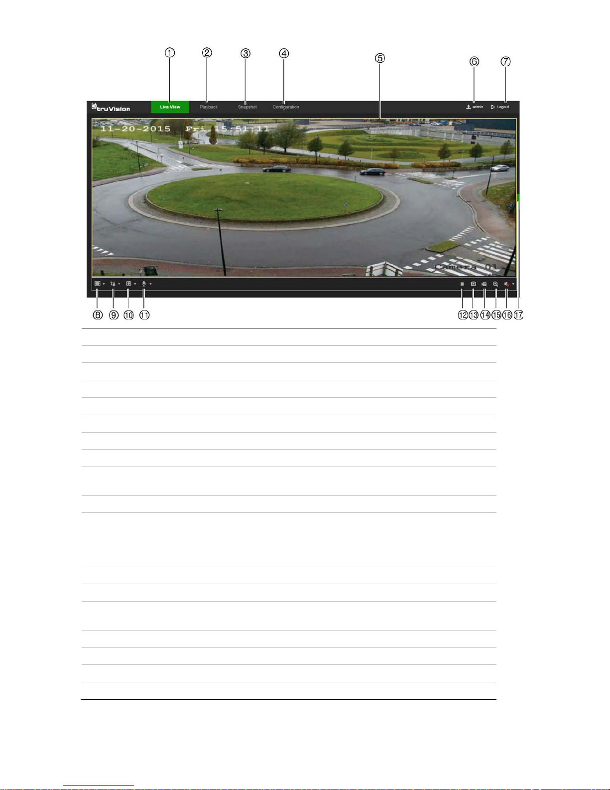
Name
Description
1. Live view tab Click to view live video.
2. Playback tab Click to play back video.
3. Snapshot tab Click to search for snapshots.
4. Configuration tab Click to display the configuration window for setting up the camera.
5. Viewer View live video. Time, date, and camera name are displayed here.
6. Current user Displays current user logged on.
7. Logout Click to log out from the system. This can be done at any time.
8. Aspect ratio Click this drop-down list to select an aspect ratio (4:3, 16:9,
Original, or Auto) and adjust the layout of the live view.
9. Stream type Click this drop-down list to select main stream or sub stream.
10. Plug-in switch Click this drop-down list to select the plug-in.
For IE users, web components and QuickTime are selectable. For
non-IE users, web components, QuickTime, VLC, or MJPEG are
selectable if they are supported by the web browser.
11. Bi-directional audio Turn the microphone on or off.
12. Start/stop live view Click to start/stop live view.
13. Snapshot Click to take a snapshot of the video. The snapshot will be saved to
the default folder in JPEG or BMP format.
14. Start/stop recording Click to record live video.
15. Digital zoom Click to enable digital zoom.
16. Audio Adjust the volume.
17. PTZ controls Direction actions, zoom, focus, iris, light, and wiper control.
6 TruVision 81 Series IP Camera Configuration Manual
Camera configuration
This chapter explains how to configure the cameras using a web browser.
After the camera hardware has been installed, configure the camera’s settings using
the web browser. Administrator rights are required to configure the cameras over the
internet.
The camera web browser permits configuration of the camera remotely using a PC.
Web browser options may vary depending on camera model.
Configuration panel overview
Use the Configuration panel to configure the server, network, camera settings, alarms,
users, transactions, and other parameters such as upgrading the firmware.
This section contains images and descriptions of each of the configuration panel
windows.
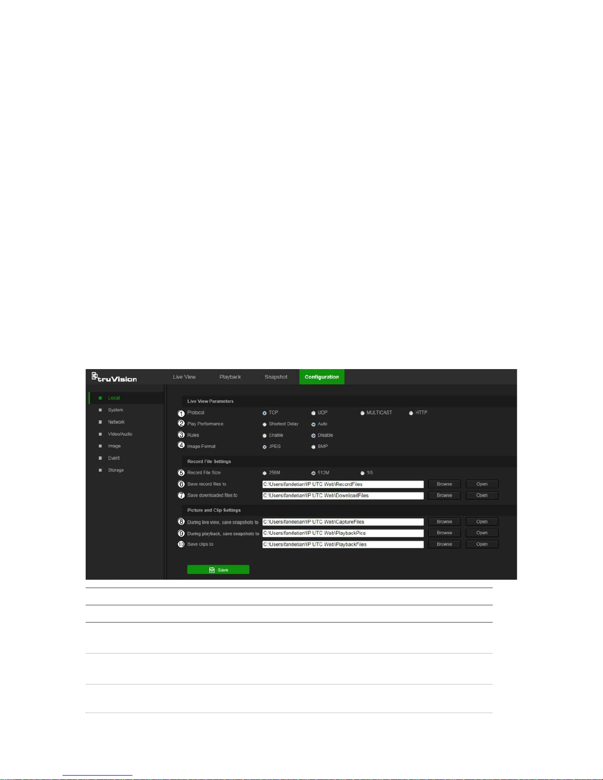
Local
Use the Local window to manage the protocol type, live view performance, and local
storage paths. In the Configuration panel, click Local to display the local configuration
window.
Parameters Description
Live View Parameters
1.
Protocol
Specifies the network protocol used.
Options include: TCP, UDP, MULTICAST, and HTTP.
2.
Live View Performance
Specifies the transmission speed.
Options include: Shortest Delay or Auto.
3.
Rules
Specifies Live View displ ay rules. Select Enable to tag a
moving object with green rectangles.
TruVision 81 Series IP Camera Configuration Manual 7
Parameters Description
4.
Image Format
Choose the image format for a snapshot: JPEG or BMP.
Record File Settings
5.
Record F
ile Size Specifies the maximum file size.
Options include: 256M, 512M, and 1G.
6.
Save
Record Files to Specifies the directory for recorded files.
7.
Save
Downloaded Files to Specifies the directory for downloaded files.
Picture and Clip Settings
8.
During live view, s
ave
s
napshots to
Specifies the directory for saving snapshots in live view mode.
9.
During playback, s
ave
s
napshots to
Specifies the directory for saving snapshots in playback mode.
10.
Save Clips To
Specifies the directory for saving video clips in playback mode.
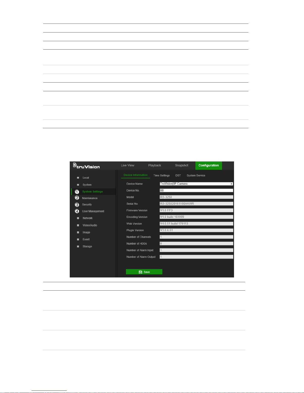
System
Use the System window to configure basic device information, system time, users,
security settings, and other parameters such as upgrading the firmware.
System submenus Description
1.
System
settings Defines device basic information including
SN and the current firmware
version and time settings (see “System time” on page 9). Also contains
camera hardware options (see “System service” on page 13).
2.
Maintenance
Perform functions such as device reboot, set to default, export and
import configuration files, and firmware upgrade. Also contains an
exportable event log list. See “Maintenance” on page 51.
3.
Security
Defines who can use the camera, their passwords and access
privileges, RTSP authentication, IP address filter, and log in lo c k. See
“Security” on page 50.
8 TruVision 81 Series IP Camera Configuration Manual
System submenus Description
4.
User
management
Add or delete users and see which users are currently online. See
“User management” on page 47.
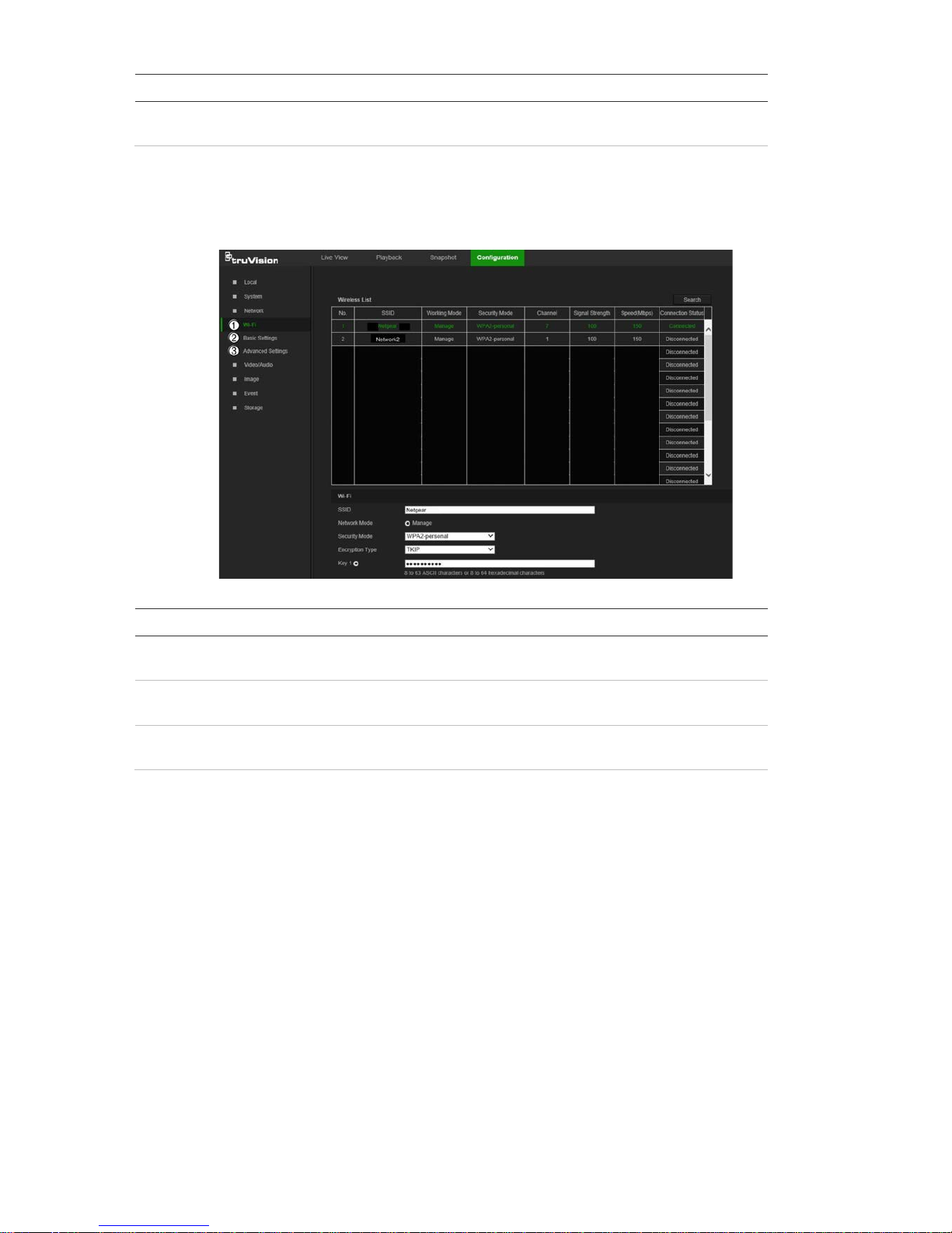
Network
Use the Network window to set up and monitor Wi-Fi cameras and define basic and
advanced network setti ng s.
Network submenus Description
1.
Wi
-Fi Defines Wi-Fi and WPS settings, and shows available wireless
networks (see “Wi-Fi” on page 14).
2.
Basic settings
Defines TCP/IP, DDNS, Port, and NAT settings (see “Basic settings”
on page 15).
3.
Advanced
settings
Defines FTP, Email, HTTPS, and QoS settings (see “Advanced
settings” on page 18).
Video/Audio
Use the Video/Audio window to define recording parameters for video, audio, and
region of interest (ROI).
TruVision 81 Series IP Camera Configuration Manual 9
Image
Use the Image window to define the image display settings, OSD settings, overlay text,
and privacy mask. See “Image” on page 24 for further information on setup.
Event
Use the Event window to set up alarms by defining area settings, arming schedules,
and linkage methods.
10 TruVision 81 Series IP Camera Configuration Manual
Event submenus Description
1.
Basic
event Defines motion detection, video tampering, alarm input/output,
exception, and PIR alarm. See “Motion detection alarms” on page 30,
“Tamper-proof alarms” on page 35, “Exception alarms” on page 36,
“Alarm inputs and outp uts” on page 36, and “PIR alar m ” on page 37.
2.
Smart
event Defines intrusion and line crossing detection.
Storage
Use the storage window to define recording schedule, storage management, network
attached storage (NAS) configuration, and snapshot configuration.
Storage submenus Description
1.
Schedule
settings
Configure recording settings and snapshot captures for all available
event types on a daily basis.
2.
S
torage
management
Manage hard drive storage space by file type and configure NAS
drives.
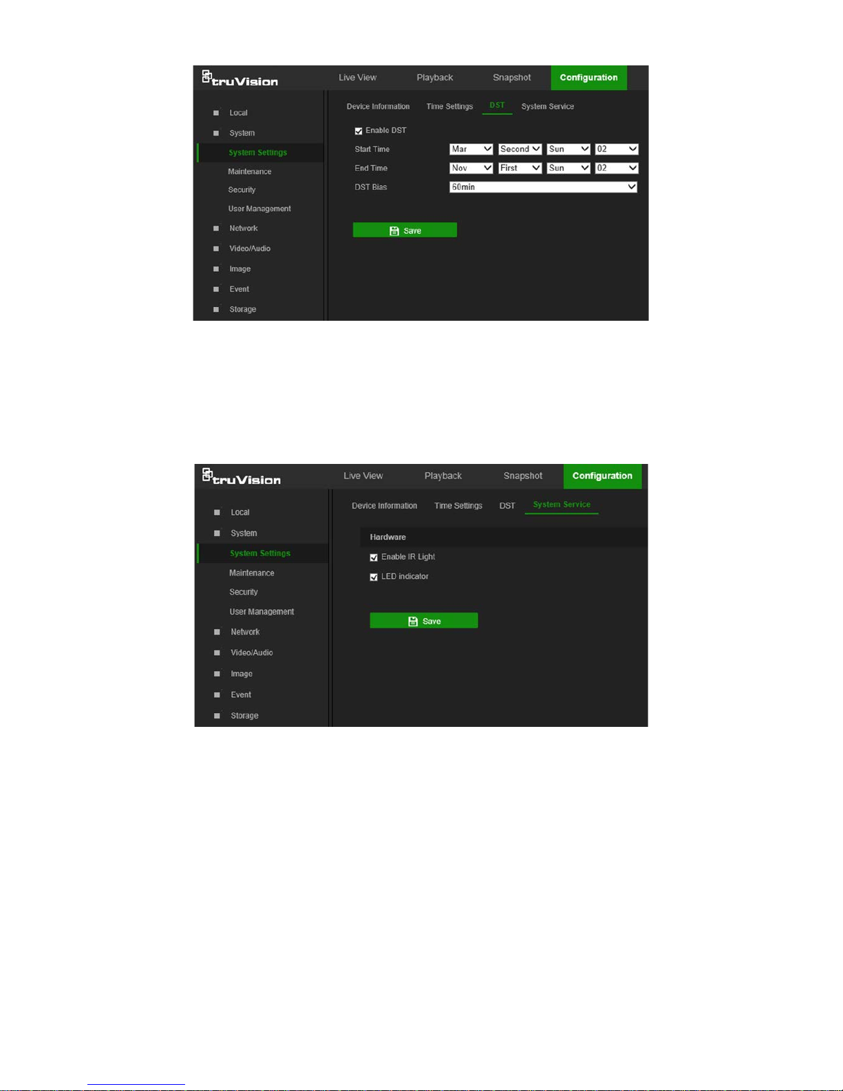
System time
Network Time Protocol (NTP) is a protocol for synchronizing the clocks of network
devices, such as IP cameras and computers. Connecting network devices to a
dedicated NTP time server ensures that they are all synchronized.
TruVision 81 Series IP Camera Configuration Manual 11
To define the system time and date:
1. From the menu toolbar, click Configuration > System > System Settings > Time
Settings.
2. From the Time Zone drop-down list, select the time zone that corresponds to the
camera’s location.
3. Select one of the following options for setting the time and date:
Synchronize with an NTP server: Select the NTP radio button and type the
required information in the Server Address and NTP Port boxes. The time interval
can be set from 1 to 10080 minutes.
—or—
Set manually: Select the Manual Time Sync radio button and then click
to set
the system time from the pop-up calendar.
Note: Select the Sync with computer time checkbox to synchronize the time of the
camera with the time of the computer.
4. Click Save to save changes.
5. Click the DST tab and then select Enable DST to enable the DST (Daylight Savings
Time) function, and set the date of the DST period.
6. Set the date and time differen ti al of the DST period using the Start Time, End
Time, and DST Bias drop-down lists.
12 TruVision 81 Series IP Camera Configuration Manual
7. Click Save to save changes.
System service
System service hardware settings enable or disable camera LED functions. These
LEDs are selected by default.
• Select or deselect Enable IR Light to turn the infrared LED indi c ator on or o ff.
• Select or deselect LED indicator to turn the LED indicator(s) on or off. See the
camera installation guide for further information on LED functions.
TruVision 81 Series IP Camera Configuration Manual 13

Network settings
Accessing the camera through a network requires the definition of certain network
settings. Use the Network menu to define these settings.
Wi-Fi
Define Wi-Fi and WPS parameters in the Wi-Fi window.
Note: Follow the recommended camera installation instructions in the installation guide
before defining parameters.
To define the Wi-Fi parameters:
1. Click Configuration > Network > Wi-Fi.
2. Click Search to search the online wireless connections.
3. Click on a wireless connection in the list to select it.
4. Select Manage as the N etwork Mode.
5. Make a selection from the Security Mode drop-down list (Not-encrypted, WEP,
WPA-personal, WPA-enterprise, WPA2-personal, or WPA2-enterprise).
6. Define encryption and authentication parameters based on the security mode
selected.
7. Click Save to save changes.
To define the WPS parameters:
1. Select the Enable WPS check box and then select one of the following connection
methods:
Push button connection (PBC): Push the WPS button on the wireless router
device and the WPS indicator starts flashing. (The WPS settings may be different
according to device type. Refer to the wireless router’s user manual for details).
14 TruVision 81 Series IP Camera Configuration Manual

Select the PBC Connection radio button and click Connect. The camera and the
wireless network router connect automatically.
—or—
Router PIN mode: Locate the PIN code printed on a sticker or directly on the router.
Select the Use router PIN code radio button, type the PIN code in the Router PIN
Code box, and click Connect to connect the camera to the wireless router.
2. Click Save to save changes.
Basic settings
Menu tabs Description
1.
TCP/IP
NIC Type: Select the NIC type from the drop-down list. Default is Auto.
Other options include 10M Half-dup, 10M Full-dup, 100M Half-dup, and
100M Full-dup.
DHCP: Select DHCP to automatically obtain an IP address and other
TruVision 81 Series IP Camera Configuration Manual 15

Menu tabs Description
network settings from that server.
IPv4 Address: If necessary, type in the IPv4 address of the camera.
IPv4 Subnet Mask: If necessary, type in the IPv4 subnet mask.
IPv4 Default Gateway: If necessary, type in
the IPv4 gateway IP address.
IPv6 Mode: Select Manual, DHCP, or Router Advertisement from the
drop-down list.
IPv6 Address: Type in the IPv6 address of the camera.
IPv6 Subnet Mask: Type in the IPv6 subnet mask.
IPv6 Default Gateway: Type in the IPv6 gateway IP address.
Mac Address: If necessary, type in the MAC address of the devices.
MTU: Type in the valid value range of MTU. Default is 1500.
Multicast Address: Enter a D-class IP address between 224.0.0.0 to
239.255.255.255. Only specify this option if using the multicast function.
Some routers prohibit the use of multicast function in case of a network
storm.
Enable Multicast Discovery: Enables the automatic detection of the
online network camera via private multicast protocol in the LAN.
DNS server: Specifies the DNS server for the network.
See page 17 for setup information.
2.
DDNS
DDNS is a service that maps Internet domain names to IP addresses. It is
designed to support dynamic IP addresses , suc h as thos e assign ed b y a
DHCP server. DDNS permits remote connection to the camera’s network;
however the router serving that network must be configured properly for
remote access.
Make a selection from the DDNS Type drop-down list (IPServer,
DynDNS, ezDDNS, or NO-IP).
DynDNS (Dynamic DNS): Manually create a host name. A user account
must first be created us ing the DynDNS.org hosting web site.
ezDDNS: Activate the DDNS auto-detection function to set up a dynamic
IP address. The server is set up to assign an available host name to the
recorder.
IPServer: Type in the address, host name, and user name for the IP
Server.
See page 17 for setup information.
3.
Port
HTTP Port: The HTTP port is used for remote internet browser access.
Enter the port used for the IE browser. Default value is 80.
RTSP Port: RTSP (Real Time Streaming Protocol) is a network control
protocol designed for use in entertainment and communications systems
to control streaming media servers. Enter the RTSP port value. The
default port number is 554.
HTTPS Port: HTTPS (Hyper Text Transfer Protocol Secure) allows video
to be securely viewed when using a browser. Enter the HTTPS port,
value. The default port number is 443.
Server Port: This is used for remote client software access. Enter the
server port value. The default port number is 8000.
Alarm Host IP: Specifies the IP address of the alarm host.
Alarm Host Port: Specifies the port of the alarm host.
See page 17 for setup information.
4.
NAT
A NAT (Network Address Translation) is used for network connection.
Select Auto or Manual from the Port Mapping Mode drop-down lis t . See
page 18 for setup information.
16 TruVision 81 Series IP Camera Configuration Manual

To define the TCP/IP parameters:
1. From the menu toolbar, click Configuration > Network > Basic Settings > TCP/IP.
2. Configure the NIC settings, including the NIC Type, IPv4 settings, IPv6 settings,
MTU, and Multicast Address.
3. If a DHCP server is available, select the DHCP checkbox.
4. If the DNS server settings are required for some applications (e.g., sending email),
configure the Preferred DNS Server or Alternate DNS Server.
5. Click Save to save changes.
Note: Click the Wlan tab to configure the Wlan settings.
To define the DDNS parameters:
1. From the menu toolbar, click Configuration > Network > Basic Settings > DDNS.
2. Select the Enable DDNS check box to enable this feature.
3. Select DDNS Type:
• DynDNS: Enter the DNSS server address, members.ddns.org, which is used to
notify DDNS about changes to the IP address, the host name for the camera, the
port number (443 (HTTPS)), and the user name and password used to log into
the DDNS account. The domain name displayed under “Host Name” is the one
created on the DynDNS web site.
• ezDDNS: Type the required host name in the Host Name box. The default host
name is the utc-serial num ber . The default server address is www.tvr-ddns.net,
which cannot be changed. Click Get URL to register generate a URL that, when
copied and pasted into a browser, generates an IP address for the camera for
remote access.
Note: The camera’s network router must be configured for remote acces s.
• IPServer: Type the addre ss of the IP Server.
• NO-IP: Type www.noip.com into the Server Address box and create a domain
name.
4. Click Save to save changes.
To define the port parameters:
1. From the menu toolbar, click Configuration > Network > Basic Settings > Port.
2. Set the HTTP port, RTSP port, HTTPS port and Server port of the camera.
HTTP Port: The default port number is 80, and it can be changed to any port No.
which is not occupied.
RTSP Port: The default port number is 554. It can be changed to any port number
in the range from 1 to 65535.
HTTPS Port: The default port number is 443. It can be changed to any port number
that is not occupied.
TruVision 81 Series IP Camera Configuration Manual 17
Server Port: The default server port number is 8000. It can be changed to any port
number in the range from 2000 to 65535.
3. Type the IP address and port to upload the alarm information to the remote al ar m
host. Also, select the Notify Alarm Recipient option in the Normal Linkage of each
event page.
4. Click Save to save changes.
To set up the NAT parameters:
Network Address Translation (NAT) permits automatic communication with a network
router.
1. Click Configuration > Network > Basic Settings > NAT.
2. Select the Enable UPnP check box to enable the NAT function.
3. Select Auto or Manual from the Port Mapping Mode drop-down list. When Manual
is selected, click on an external port number to change it by typing in a new port
number.
Note: If a non-default external port number is assigned, the network router settings
must be configured accordingly.
4. Click Save to save changes.
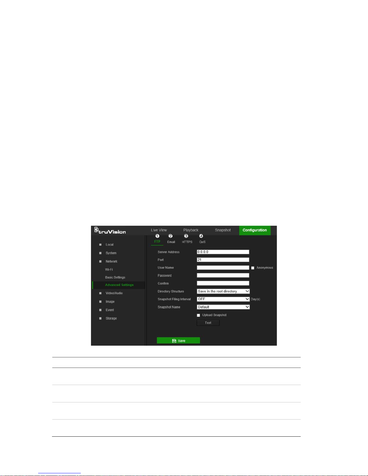
Advanced settings
Menu tabs Description
1.
FTP
Enter the FTP address and folder to which camera snapshots can be
uploaded. See page 19 f or s etup inf ormation.
2.
Email
Enter the email address to which messages are sent when an alarm
occurs. See page 19 for setup information.
3.
HTTPS
Specifies authentication of the website and its associated web server,
which protects against Man-in-the-middle attacks.
4.
QoS
QoS (Quality of Service) can help solve network delay and congestion by
configuring the priority of data sending. See page 21 for setup information.
18 TruVision 81 Series IP Camera Configuration Manual

To define the FTP parameters:
1. From the menu toolbar, click Configuration > Network > Advanced Settings >
FTP.
2. Configure the FTP settings, including the Server Address, Port, User Name,
Password, Directory Structure, and upload type.
Anonymous: Select this check box to enable anonymous access to the FTP server.
Directory Structure: Select the Save in the root directory, Save in the parent
directory, or Save in the child directory. When the parent directory is selected,
select Use Device Name, Use Device Number, Use Device IP, or Custom (type in
a directory name) for the name of the parent directory. If Save in the child
directory is selected, select Use Camera Name, Use Camera Number, or
Custom as the name of the child directory.
Snapshot Filing Interval: Select a number of days to specify how many days of
snapshots should be stored in a single folder. All snapshots are saved to a single
folder in default mode (OFF).
Snapshot Name: Sele ct Custom Prefix to change the default snapshot name
prefix. Invalid characters for the custom prefix are as follows: / \ : * ? ‘ “ < > | %.
Upload Snapshot: Select this check box to enable the uploading of snapshots to an
FTP server.
Test: Click Test to test the FTP parameters.
3. Click Save to save changes.
To set up the email parameters:
1. From the menu toolbar, click Configuration > Network > Advanced Settings >
Email.
2. Configure the following settings:
Sender: The name of the email sender.
TruVision 81 Series IP Camera Configuration Manual 19

Sender’s Address: The email address of the sender.
SMTP Server: The SMTP Server, IP address, or host name.
SMTP Port: The SMTP port. The def ault is 2 5.
Email Encryption: Select None, SSL, or TLS. If the Enable STARTTLS check box
is not selected after selecting SSL or TLS, e-mails are sent after encryption via SSL
or TLS. The SMTP port should be set as 465 for this encryption method. After
selecting SSL or TLS and then selecting Enable STARTTLS, emails are sent after
encryption via STARTTLS, and the SMTP port should be set as 25.
Note: When using STARTTLS, ensure that the protocol is supported by the email
server. If the Enable STARTTLS check box is selected when the protocol is not
supported by the e-mail server , e-mail will not be encrypted.
Attached Snapshot: Select the Attached Snapshot check box to send em ai l s with
attached alarm images.
Interval: This is the time between two actions of sending attached snapshots.
Authentication: If the email server requires authentication, select this check box to
use authentication to log in to this server. Enter the login user name and password.
User Name: The user name to log in to the server where the images are uploaded.
Password: Enter the pas sword.
Confirm: Confirm the password.
Receiver: Click inside the Receiver table to type in receiver names and email
addresses. Row 1 shows the first user to be notified, Row 2 shows the second user
to be notified, and so on.
3. Click Test to test the email parameters for each receiver.
4. Click Save to save changes.
To set up the HTTPS parameters:
A valid certificate must be installed to use a secure HTTPS connection for accessing
the user interface.
Caution: Removing and installing certificates is only recommended for advanced
users.
1. Click Configuration > Network > Advanced Settings > HTTPS.
20 TruVision 81 Series IP Camera Configuration Manual

2. Deselect Enable and click Save to remove the default certificate.
3. To create a self-signed certificate:
Select the Create Self-signed Certificate radio button and then click Create. Enter
the country, host name/IP, validity, and the other information requested.
—or—
To create a certificate request:
Select the Signed Certificate is available, Start the installation directly radio
button and then click Create. Upload the certificate to the device.
—or—
To create an authorized certificate:
Select the Create the certificate request first and continue the installation as
radio button and then click Create. Fill in the required information in the popup
window. Download the certificate request and submit it to the trusted certificate
authority (such as Symantec or RSA) for signature. After receiving the signed valid
certificate, upload the cer t ific a te to t he dev i c e.
4. Click OK to save the settings.
To define the QoS parameters:
1. From the menu toolbar, click Configuration > Network > Advanced Settings >
QoS.
2. Configure the QoS settings, including Video/Audio DSCP, Event/Alarm DSCP,
and Management DSCP. The valid value range of the DSCP is 0-63. The higher
the differentiated services code point (DSCP) value, the higher the priority of the
service.
3. Click Save to save changes.
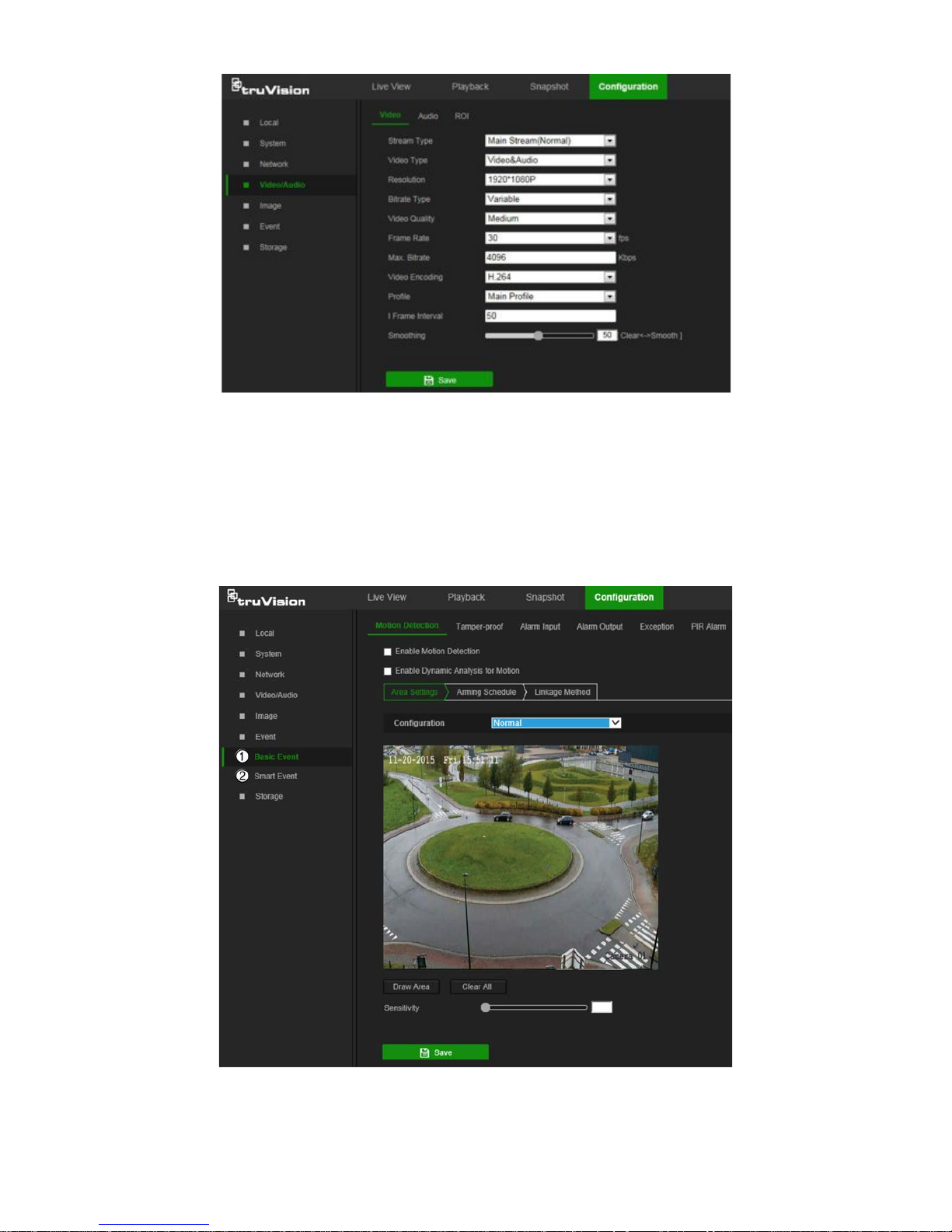
Video/Audio
Adjust the video and audio recording parameters to obtain the required picture quality
and file size.
TruVision 81 Series IP Camera Configuration Manual 21

Tab Parameter descriptions
1.
Video
Stream Type: Specifies the streaming method used.
Options include: Main Stream (Normal), Sub Stream and Third
stream.
Video Type: Specifies the stream type for recording.
Select Video Stream to record video stream only. Select
Video&Audio to record both video and audio streams.
Note: Video&Audio is only available for those camera models that
support audio.
Resolution: Specifies the recording resolution. A higher image
resolution provides a higher image quality but also requires a higher bit
rate. The resolution options listed depend on the type of camera and if
main or sub stream is being used.
Note: Resolutions can vary depending on the camera model.
Bitrate Type: Specifies whether variab le or fixed bit rate is used.
Variable produces higher quality results suitable for video downloads
and streaming.
Video Quality: Specifies the quality level of the image. It can be set
when variable bit rate is selected. Options include: Lowest, Lower,
Medium, Higher and Highest.
Frame Rate: Specifies the frame rate for the selected resolution.
The frame rate is the number of video frames that are shown or sent
per second.
Note: The maximum frame rate depends on the camera model and
selected resolution. Refer to the camera’s specifications.
Max Bitrate: Specifies the maximum allowed bit rate. To maintain high
quality image resolution, a high bit rate must also be selected.
Video Encoding: Specifies the video encoding used.
Profile: Different profile options indicate different tools and
technologies used in compression. Options include: High Profile,
Main
Profile, and Basic Profile.
22 TruVision 81 Series IP Camera Configuration Manual

Tab Parameter descriptions
I Frame Interval: A video compression method. We strongly
recommended not changing the default value of 50.
Smoothing: Adjust the smoothness of the stream.
2.
Audio
(Desktop
camera only)
Audio Encoding: G.722.1, G.711ulaw, G.711alaw, MP2L2, G.726,
and PCM encoding standards are selectable.
Sampling Rate: Set the frequency of samples per second. Higher
settings result in higher quality audio.
Audio Stream Bitrate: Bit rate settings from 32-160 kbps are
selectable. The higher the bit rate setting, the larger the audio file
generated.
Audio Input: MicIn is selectable for the connected microphone.
Input Volume: Specifies the volume from 0 to 100.
Environmental Noise Filter: Set as OFF or ON to filter environmental
.
noise.
3.
ROI
Define a region of interest (ROI) within the camera view. Assigns more
encoding resources to an ROI (background information is less focused
when network performance is less than optimal).
To configure ROI settings:
1. From the menu toolbar, click Configuration > Video/Audio > ROI.
2. Click Draw Area to draw the region of interest on the image. One region can be
drawn.
TruVision 81 Series IP Camera Configuration Manual 23

3. Select the stream type from the Stream Type drop-down list to set the ROI
encoding.
4. Select Enable under Fixed Region to manually configure the area.
Region No.: Select the region.
ROI Level: Choose the image quality enhancing level.
Region Name: Type the required region na me.
5. Click Save to save changes.
Image
The camera image may need to be adjusted to obtain the best image qualitydepending
on the camera model or location background. Adjust the brightness, contrast, saturation,
hue, and sharpness of the video image using the Image menu.
Use this menu to also adjust camera behavior parameters such as exposure time, iris
mode, video standard, day/night mode, image flip, WDR, digital noise reduction, white
balance, and indoor/ou tdoor mo de.
Parameter Description
1.
Image
Settings
Auto D/N
Switch The camera automatically switches between day and night modes.
All image settings remain the same for both modes.
24 TruVision 81 Series IP Camera Configuration Manual

Parameter Description
Scheduled D/N
S
ettings
The camera switches between day and night modes according to
the configured schedule. The start and end times shown are for
day mode. The other time period is for night mode.
There are three tabs to configure the day/night settings:
Common: The settings are identical for both day and night modes
for Exposure Settings ( Ir is Mode) , Day/Night Switch, and Video
Adjustment.
Day: Configure Image Adjustment, Exposure Settings, Backlight
Settings, White Balance, and Image Enhancement settings for day
mode only.
Night: Configure Image Adjustment, Exposure Settings, Backlight
Settings, White Balance, and Image Enhancement settings for
night mode only.
Custom 24h Settings
This is used when the camera is in an outdoor situation where the
day and night is defined by the amount of daylight or a trigger via
an alarm input. Consequently, no schedule is required for the D/N
switch.
The camera has specific image settings for day and night
situations. There are three tabs to configure the day/night settings:
Common: Both day and night settings are identical for Exposure
Settings (Iris Mode), Day/Night Switch, and Video Adjustment.
Day: Configure the Exposure Settings (Exposure Time and Gain),
Backlight Settings, White Balance, and Image Enhancement
settings for day mode only.
Night: Configure Image Adjustment (Brightness, Contrast, and
Sharpness), Exposure Settings (Exposure Time and Gain),
Backlight, White Balance, and Image Enhancement settings for
night mode only.
TruVision 81 Series IP Camera Configuration Manual 25

Parameter Description
2.
Image Adjustment
Brightness
, Contrast
S
aturation, Hue,
Sharpness
Modify the different elements of picture quality by adjusting the
values for each parameter.
3.
Exposure Settings
Iris Mo
de There are two settings, Auto and Manual. The type of lens
determines which setting is used.
Exposure Time
The exposure time controls the length of time that the aperture is
open to let light into the camera through the lens.
Select a higher value if the image is dark and a lower value to see
fast moving objects.
Gain
Select the value to adjust the image brightness.
4.
Day/Night Switch
Day/Night
Switch Defines whether the camera is in day or night mode. The day
(color) option could be used, for example, if the camera is located
indoors where light levels are always good.
Options:
Day: Camera is always in day mode.
Night: Camera is always in night mode.
Auto: The camera automatically detects which mode to use.
Schedule: The camera switches between the day mode and the
night mode according to the configured time period.
Triggered by Alarm Input: The camera switches to the day mode
or the night mode after the alarm is triggered.
Sensitivity
Only available when Auto D/N switch mode is selected. It defines
the sensitivity of the switch between day and night. Sensitivity can
be set anywhere from 0 to 7.
Delay
Time Only available when Auto D/N switch mode is selected. The delay
time refers to the interval time between the day/night switchover. It
can be set from 5 to 120 seconds.
Smart
IR When enabled (ON), this setting can help to avoid over-exposure
of
an image due to IR LED glare.
Mode
The Mode drop-down list appears when the smart supplement light
is enabled.
Auto: The camera adjusts the IR LED automatically to avoid over-
exposure.
Manual: Enables the Distance slider so that IR distance controlling
can be increased or decreased.
Distance
Move the slider to increase or decrease the IR transmission
distance.
Enable
IR Light Select ON or OFF to enable/disable IR.
Enable: The IR illuminators are ON when the camera turns into
night mode.
Disable: The IR illuminators are OFF when the camera turns into
night mode.
Note: The IR illuminators always are OFF in day mode.
26 TruVision 81 Series IP Camera Configuration Manual

Parameter Description
LED indicator
Select ON or OFF to enable/disable LEDs. See the Installation
Guide for a description of LED functions.
Enable: The LEDs will be ON when the camera is in the mode
selected (Common, Day, or Night).
Disable: The LEDs will be OFF when the camera is in the mode
selected (Common, Day, or Night).
Note: The LEDs always are ON if the camera is connected to the
network with an Ethernet cable.
5.
Backlight Settings
BLC
Area If the camera is focused on an object against strong backlight, the
object will be too dark to be seen clearly. BLC compensates for the
background light so that the image in the foreground is clear. OFF,
Up, Down, Left, Right, and Center are selectable. When WDR is
enabled, BLC cannot be configured.
WDR
When enabled, this feature (wide dynamic range) shows details of
objects in shadows or details of objects in bright areas of frames
that have high contrast between light and dark areas.
6.
White
Balance
White Balance
White balance (WB) sets the relative parameters for the color white
in the camera. Based on this information, the camera continues to
display all colors correctly even when the color temperature of the
scene changes such as from daylight to fluorescent lighting.
Select one of the options:
AWB1: Apply for small range of 2500 to 9500 K, for environments
where the lighting is always stable.
Locked WB: Locks the WB to the current environment color
temperature.
Incandescent Lamp: For use with incandescent lighting.
Warm Light Lamp: For use where the indoor light is warm.
Natural Light: For use with natural light.
Fluorescent Lamp: For use where there are fluorescent lamps
installed near the camera.
7.
Image Enhancement
Digital
Noise
Reduction
Digital noise reduction (DNR) reduces noise, especially in low light
conditions, to improve image performance.
Options include: Normal mode, Advanced mode, or OFF.
Noise Reduction
Level
Only available when DNR is set to Normal Mode. Set the level of
noise reduction to a hi gher value for stronger noise reduction.
Time/Space DNR
Level
Set the level of noise reduction level in Advanced mode.
Note: Setting high values may result in an unclear image.
8.
Video Adjustment
Mirror
Inverts the image. Options are Left/Right, Up/Down, Center, and
OFF.
TruVision 81 Series IP Camera Configuration Manual 27

Parameter Description
Hallway View
To invert the 16:9 aspect ratio, enable the rotate function. This
function is best used when installing the camera in a scene with a
narrow angle of view.
During installation, turn the camera to 90 degrees or rotate the
3-axis lens to 90 degrees, and then set the rotate mode as ON. A
normal view of the scene with 9:16 aspect ratio that ignores
needless information such as the walls appears.
Video Standard
PAL(50Hz) and NTSC(60Hz) are selectable. Choose according to
the video standard required.
Capture Mode
Set the required frame rate to meet the different demands of field of
view and resolution. A higher frame rate may be needed in a
location with a lot of movement (such as a money depot).
Note: Click the Default button to return all the image settings to default values.
OSD (On Screen Display) Settings
In addition to the camera name, the camera also displays the system date and time on
the screen. How the text appears on screen can also be defined.
To position the on-screen date/time and name:
1. From the menu toolbar, click Configuration > Image > OSD Settings.
2. Select the Display Name check box (1) to display the on-screen camera name.
3. Select the Display Date check box (2) to display the date/time on screen.
4. Select the Display Week check box (3) to include the day of the week in the on-
screen display.
5. In the Camera Name box (4), type the camera name.
6. Select the time and date formats from the Time format and Date format drop-down
lists (5).
7. Select a display mode for the camera from the Display Mode drop-down list (6).
Display modes include:
28 TruVision 81 Series IP Camera Configuration Manual

• Tr ansparent & Not flashing. The image appears through the text.
• Tr ansparent & Flashing. The image appears through the text. The text flashes
on and off.
• Not transparent & Not flashing. The image is behind the text. This is the
default setting.
• Not transparent & Flashing. The image is behind the text. The text flashes on
and off.
8. Select the OSD size (7). Pixel display options include Auto, 16*16, 32*32, 48*48,
and 64*64.
9. Select the OSD font color (8). Options include Black&White Self-adaptive and
Custom. Use the color picker to assign a font color after selecting Custom.
10. Select the alignment (9). Options include Align Right, Align Left, and Custom.
11. Click Save to save changes.
Note: When the display mode is set as transparent, the text varies according the
background. With some backgrounds, the text may not be easy to read.
Text overlay
Add up to four lines of on-screen text in the Text Overlay section. This option can be
used to display emergency contact details and/or other information. Each text line can
be positioned anywhere on the screen.
To add on-screen text:
1. From the menu toolbar, click Configuration > Image.
2. In the Text Overlay section, select check box 1.
3. Type the text in the text box.
4. Use the mouse to click and drag the red text in the live view window to adjust the
text overlay position.
5. Repeat steps 2 to 4 for each extra line of text, selecting the next string number.
Note: Remove overlay text by deselecting its corresponding check b ox.
6. Click Save to save changes.
Privacy mask
Privacy masks allow concealment of sensitive areas (such as neighboring windows) to
protect them from view on the monitor screen and in the recorded video. The masking
appears as a blank area on-screen. Up to four privacy masks can be created per
camera.
Note: There may be a small difference in size of the privacy mask area depending on
whether local output or the web browser is used.
TruVision 81 Series IP Camera Configuration Manual 29

To add a privacy mask area:
1. From the menu toolbar, click Configuration > Image > Privacy Mask.
2. Select the Enable Privacy Mask check box.
3. Click Draw Area.
4. Click and drag the mouse in the live video window to draw the mask area.
5. Click Stop Drawing to finish drawing, or click Clear All to clear all of the areas set
without saving them.
6. Click Save to save changes.
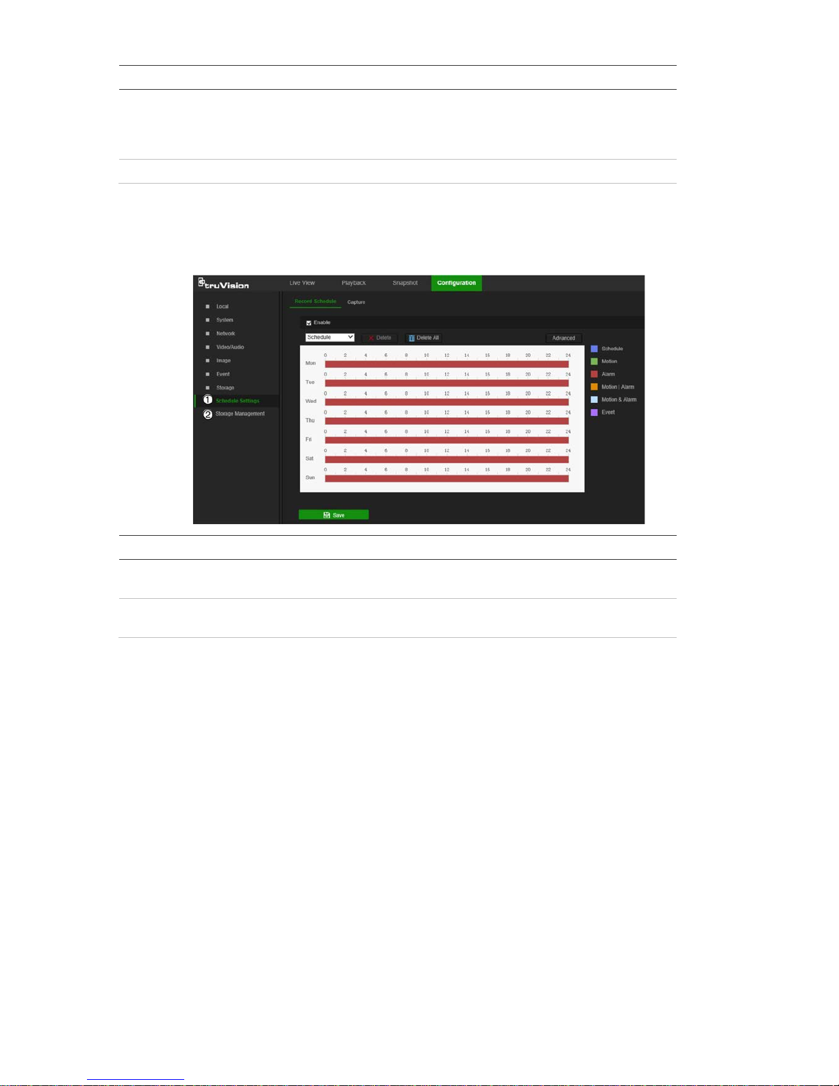
Basic event
Motion detection alarms
A motion detection alarm refers to an alarm triggered when the camera detects motion.
The motion alarm is only triggered if it occurs during a programmed time schedule.
Select the level of sensitivity to motion as well as the target size so that only objects
that could be of interest trigger a motion recording. For example, the motion recording
is triggered by the movement of a person but not that of a cat.
Define the area on-screen where the motion is detected, the level of sensitivity to
motion, the schedule when the camera is sensitive to detecting motion, as well as
which methods are used to produce a motion detection alarm.
Dynamic analysis for motion can also be enabled. When there is motion, the motion
area is indicated by green rectangles.
30 TruVision 81 Series IP Camera Configuration Manual

Defining a motion detection alarm requires the following tasks:
1. Area settings: Define the on-screen area that can trigger a motion detection alarm
and the detection sensitivity level.
2. Arming schedule: Define the schedule during which the system detects motion.
3. Linkage: Specify the method of response to the alarm (see below). Trigger
Recording must be selected to launch recordings to be stored on the SD card or in
NAS.
4. Normal and advanced configuration: Normal configuration permits setting the
sensitivity level of the motion detection. Advanced configuration provides more
control over how motion is detected. It permits setting the sensitivity level as well a s
the percentage of the motion detection area that the object must oc c upy, selecting
day or night mode, and setting up eight differently configured defined areas.
5. Recording schedule: Define the schedule during which motion detection can be
recorded. See “Recording schedule” on pag e 41 for further information.
Note: All scheduled times are based on the 24-hour clock. Ensure that the correct
time zone and daylight saving time settings have been configured in Configuration
> System > System Settings.
Linkage methods
The linkage methods available are as follows:
TruVision 81 Series IP Camera Configuration Manual 31

Notify
Alarm Recipient Send an exception or alarm signal to the remote management
software when an event oc c urs .
Notify Surveillance Center
Triggers an audible warning locally (only applies to cameras
with an audio output).
Send
Email Sends an email to a specified address when there is a motion
detection alarm.
Note: Email settings must be configured before enabling this
option. See “To set up the email parameters” on page 19 for
further information. To send the event snapshot together with
the email, select the Attached Snapshot check box.
Upload
to Snapshot Capture a snapshot when an alarm is triggered and upload the
snapshot to NAS or an FTP server.
Note: NAS settings must be configured before uploading the
snapshot to NAS. See “NAS settings” on page 45 for further
details.
FTP settings must be configured before uploading the
snapshot to FTP.
See “To define the FTP parameters” on page
19 for further details.
To upload the snapshot to FTP and NAS when motion
detection or an alarm input is triggered, Enable Event-
triggered Snapshot must also be selected in the snapshot
parameters. See “Snapshot parameters” on page 41
for further
information.
Trigger Alarm Output
Triggers external alarm outputs when an event occurs. Select
the check boxes next to individual alarm outputs or select the
Trigger Alarm Output check box to select all outputs.
Note: This option is only supported by cameras that feature an
alarm output.
Trigger
Recording Triggers the camera recording.
To set up motion detection in normal mode:
1. From the menu toolbar, click Configuration > Event > Basic Event > Motion
Detection.
2. Select the Enable Motion Detection check box. Select Enable Dynamic Analysis
for Motion to see real-time motion events.
Note: Select Local > Rules > Disable to not have detected objects indicated by
green rectangles.
3. Select Normal from the Configur ation drop-down list.
4. Click Draw Area. Click and drag the mouse on the live video image to draw an area
sensitive to motion detection.
Note: Up to eight motion detection ar eas c an be drawn on the same image.
5. Click Stop Drawing to finish drawing. Click Clear All to delete all areas marked and
restart drawing.
6. Move the Sensitivity slider to set the sensitivity of the detection. All areas will have
the same sensitivity level.
7. Click Save to save changes.
32 TruVision 81 Series IP Camera Configuration Manual

8. Click the Arming Schedule tab to edit the arming schedule. Click and drag along
the time bars or click on a time bar to configure arming schedule times.
Note: All scheduled times are based on the 24-hour clock. Ensure that the correct
time zone and daylight saving time settings have been configured in Configuration
> System > System Settings.
9. Click
to copy the schedule to other days by selecting the corresponding check
box next to the day.
10. Click Save to save changes.
11. Click the Linkage Method tab to specify the linkage method for when an event
occurs. Select one or more response met hods for the system when an alarm is
triggered. See “Linkage methods” on page 31 for details.
12. Click Save to save changes.
To set up motion detection in advanced mode:
1. From the menu toolbar, click Configuration > Basic Event > Motion Detection.
2. Select the Enable Motion Detection check box. Check Enable Dynamic Analysis
for Motion to see where motion occurs in real-time.
Note: Select Local > Rules > Disable to not have detected objects indicated with
green rectangles.
3. Select Advanced from the Configuration drop-down list.
TruVision 81 Series IP Camera Configuration Manual 33

4. In the Image Settings drop-down list, select OFF, Auto-switch or Scheduled-
switch. Defau lt is OFF.
Auto-switch and Scheduled-switch allow permit different settings for day and nig ht
as well as different periods.
5. Select a number from the Area drop-down list and click Draw Area. Click and drag
the mouse on the live video image to draw an area sensitive to motion detection.
Note: Up to eight motion detection areas can be drawn on the same image.
6. Click Stop Drawing to finish drawing. Click Clear All to delete all areas marked and
restart drawing.
7. Move the Sensitivity slider to set the sensitivity of the detection for the selected
areas.
8. Move the Proportion of Object on Area slider to set the proportion of the object
that must occupy the defined area to trigger an alarm.
9. Click Save to save the changes for that area.
10. Repeat steps 7 to 9 for each area to be defined.
11. Click the Arming Schedule tab to edit the arming schedule. Click and drag along
the time bars or click on a time bar to configure arming schedule times.
Note: All scheduled times are based on the 24-hour clock. Ensure that the correct
time zone and daylight saving time settings have been configured in Configuration
> System > System Settings.
12. Click
to copy the schedule to other days by selecting the corresponding check
box next to the day.
13. Click Save to save changes.
14. Click the Linkage Method tab to specify the linkage method for when an event
occurs. Select one or more response methods for the system when an alarm is
triggered. See “Linkage methods” on page 31 for details.
34 TruVision 81 Series IP Camera Configuration Manual

15. Click Save to save changes.
Tamper-proof alarms
The camera can be configured to trigger an alarm when the lens is covered and take an
alarm response action.
To set up tamper-proof alarms:
1. From the menu toolbar, click Configuration > Event > Basic Event > Tamper-
proof.
2. Select the Enable check box.
3. Move the Sensitivity slider to set the sensitivity of the detection.
4. Click Save to save changes.
5. Click the Arming Schedule tab to edit the arming schedule. Click and drag along
the time bars or click on a time bar to configure arming schedule times.
Note: All scheduled times are based on the 24-hour clock. Ensure that the corr ect
time zone and daylight saving time settings have been configured in Configuration
> System > System Settings.
6. Click
to copy the schedule to other days by selecting the corresponding check
box next to the day.
7. Click Save to save changes.
8. Click the Linkage Method tab to specify the linkage method for when an event
occurs. Select one or more response methods for the system when an alarm is
triggered. See “Linkage methods” on page 31 for details.
9. Click Save to save changes.
TruVision 81 Series IP Camera Configuration Manual 35

Alarm inputs and outputs (Desktop cameras only)
To define the external alarm input:
1. From the menu toolbar, click Configuration > Event > Basic Event > Alarm Input.
2. Select the Alarm Input No. and the Alarm Type. The alarm type can be NO
(Normally Open) or NC (Normally Closed). Type a name for the alarm into the
Alarm Name box.
3. Click Save to save changes.
4. Click the Arming Schedule tab to edit the arming schedule. Click and drag along
the time bars or click on a time bar to configure arming schedule times.
Note: All scheduled times are based on the 24-hour clock. Ensure that the correct
time zone and daylight saving time settings have been configured in Configuration
> System > System Settings.
5. Click
to copy the schedule to other days by selecting the corresponding check
box next to the day.
6. Click the Copy to button to copy the schedule to other alarm inputs.
7. Click Save to save changes.
8. Click the Linkage Method tab to specify the linkage method for when an event
occurs. Select one or more response methods for the system when an alarm is
triggered. See “Linkage methods” on page 31 for details.
9. Click Save to save changes.
To define alarm output:
1. From the menu toolbar, click Configuration > Event > Basic Event > Alarm
Output.
2. Select an alarm output channel from the Alarm Output No. drop-down list. If
required, type a name for the alarm output in the Alarm Name box.
3. The delay time can be set to 5s, 10s, 30s, 1min, 2min, 5min, or 10min. The delay
time refers to the time duration that the alarm output remains in effect after the
alarm occurs.
4. Click Save to save changes.
5. Click the Arming Schedule tab to edit the arming schedule. Click and drag along
the time bars or click on a time bar to configure arming schedule times.
Note: All scheduled times are based on the 24-hour clock. Ensure that the correct
time zone and daylight saving time settings have been configured in Configuration
> System > System Settings.
6. Click the Copy to button to copy the schedule to other alarm inputs.
7. Click Manual Alarm to generate a test alarm. After setting a manual alarm, click
Clear Alarm to remove it.
8. Click Save to save changes.
36 TruVision 81 Series IP Camera Configuration Manual

Exception alarms
The camera can be configured for notification of irregular events. These exception
alarms include:
• HDD Full: All recording space of NAS or local storage is full.
• HDD Error: Errors occurred while files were being written to the storage, no storage
is present, or the storage failed to initialize.
• Network Disconnected: Disconnected network cable.
• IP Address Conflicted: Conflict in IP address setting.
• Illegal Login: Wrong user ID or password used to log in to the cameras.
To define exception alarms:
1. From the menu toolbar, click Configuration > Event > Basic Event > Exception.
2. Under Exception Type, select an exception type from the drop-down list.
3. Click the Linkage Method tab to specify the linkage method for when an event
occurs. Select one or more response methods for the system when an alarm is
triggered. See “Linkage methods” on page 31 for details.
4. Click Save to save changes.
PIR alarm (Desktop camera s only)
A PIR (Passive Infrared) alarm is triggered when an intruder moves within the
detector's field of view. The heat energy dissipated by a person, or any other warm
blooded creature such as dogs or cats, can be detected.
To define PIR alarms:
1. From the menu toolbar, click Configuration > Event > Basic Event > PIR Alarm.
TruVision 81 Series IP Camera Configuration Manual 37

2. Select the Enable check box.
3. Type the alarm name in the Alarm Name box.
4. Drag the mouse on time bar to set the arming schedule and click Save when
finished.
Note: All scheduled times are based on the 24-hour clock. Ensure that the correct
time zone and daylight saving time settings have been configured in Configuration
> System > System Settings.
5. Click Save to save changes.
6. Click the Linkage Method tab to specify the linkage method for when an event
occurs. Select one or more response methods for the system when an alarm is
triggered. See “Linkage methods” on page 31 for details.
7. Click Save to save changes.
Smart event
Intrusion detection
An area in the surveillance scene can be config ur ed to det ect w hen i ntr usi on oc cur s . I f
someone enters the area, a set of alarm actions can be triggered.
38 TruVision 81 Series IP Camera Configuration Manual

To define intrusion detection:
1. From the menu toolbar, click Configuration > Event > Smart Event > Intrusion
Detection.
2. Select the Enable check box to enable intrusion detection.
3. Click Draw Area, and then draw a rectangle on the image as the defense region.
When drawing the rectangle, connect all lines end-to-end to each other. Up to four
areas are supported. Click Clear to clear the areas drawn. The defense region
parameters can be set up separately.
Note: The drawn area can only be quadrilateral.
4. Select the region number to be configured fr om the Region drop-down list.
5. Set the sliders as follows:
Threshold: This is the time threshold that the object remains in the region. If the
value is set as 0, the alarm is triggered immediately after the object enters the
region. The range is between 0 and 100.
Sensitivity: The sensitivity value defines the size of the object that can trigger the
alarm. When the sensitivity is high, a small object can trigger the alarm. The range
is between 1 and 100.
Percentage: This defines the ratio of the in-region part of the object that can trigger
an alarm. For example, when the percentage is set as 50%, half of the object
entering the region will trigger the alarm. The range is between 1 and 100.
6. Click Save to save changes.
TruVision 81 Series IP Camera Configuration Manual 39

7. Click the Arming Schedule tab to edit the arming sche dul e. Click and drag along
the time bars or click on a time bar to configure arming schedule times.
Note: All scheduled times are based on the 24-hour clock. Ensure that the correct
time zone and daylight saving time settings have been configured in Configuration
> System > System Settings.
8. Click
to copy the schedule to other days by selecting the corresponding check
box next to the day.
9. Click Save to save changes.
10. Click the Linkage Method tab to specify the linkage method for when an event
occurs. Select one or more response methods for the system when an alarm is
triggered. See “Linkage methods” on page 31 for details.
11. Click Save to save changes.
Cross line detection
This function can be used to detect people, vehicles, and objects crossing a pre-defined
line or an area on-screen. The line crossing direction can be set as unidirectional or bidirectional. Unidirectional is crossing the line from left to right or from right to left. Bidirectional is crossing the line from both directions.
A series of linkage methods can be triggered if an object is detected crossing the line.
To define cross line detection:
1. From the menu toolbar, click Configuration > Event > Smart Event > Cross Line
Detection.
40 TruVision 81 Series IP Camera Configuration Manual

2. Select the Enable check box to enable the function.
3. Click Draw Area. A crossing plane appears on the image.
4. Click the line and two red squares that appear at each end. Drag one of the red
squares to define the arming area.
Select the direction as A<->B, A ->B, or B->A from the drop-down list:
• A<->B: Only the arrow on the B side is displayed. When an object moves across
the plane in both directions, it is det ec ted and al ar ms ar e tri g g er ed.
• A->B: Only an object crossing the pre-defined line from the A to the B side can
be detected and trigger an alarm.
• B->A: Only an object crossing the pre-defined line from the B to the A side can
be detected and trigger an alarm.
5. Set the sensitivity level between 1 and 100.
6. If required, select another line crossing area to configure from the Line drop-down
list and repeat steps 3-5. Up to four line crossing areas can be configured.
7. Click Save to save changes.
8. Click the Arming Schedule tab to edit the arming schedule. Click and drag along
the time bars or click on a time bar to configure arming schedule times.
Note: All scheduled times are based on the 24-hour clock. Ensure that the correct
time zone and daylight saving time settings have been configured in Configuration
> System > System Settings.
9. Click
to copy the schedule to other days by selecting the corresponding check
box next to the day.
10. Click Save to save changes.
11. Click the Linkage Method tab to specify the linkage method for when an event
occurs. Select one or more response methods for the system when an alarm is
triggered. See “Linkage methods” on page 31 for details.
12. Click Save to save changes.
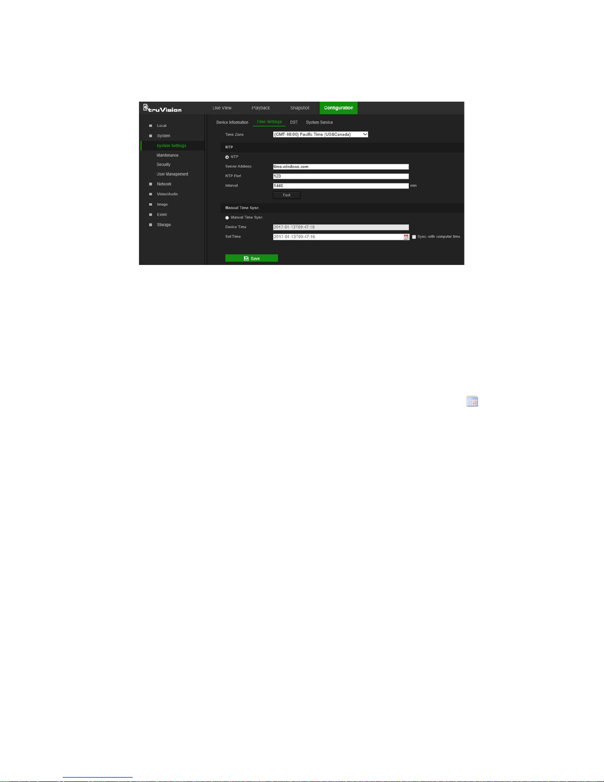
Schedule settings
Recording schedule
Use the Record Schedule window to define a recording schedule for the camera. The
recording is saved to the SD card or the NAS in the camera. The camera’s SD card
provides a backup in case of network failure.
The selected recording schedule applies to all alarm types.
TruVision 81 Series IP Camera Configuration Manual 41

To set up a recording schedule:
1. From the menu toolbar, click Configuration > Storage > Schedule Settings >
Record Schedule.
2. Select the Enable check box to enable recording.
Note: To disable recording, deselect the option.
3. Click Advanced to set the camera record parameters. Select Overwrite to
overwrite the recording. Configure Pre-record, Post-record, and Stream Type.
Pre-record time
The pre-record time is set to start recording before the scheduled time or event. For
example, if an alarm triggers recording at 10:00, and the pre-record ti me is set as 5
seconds, the camera starts to record at 9:59:55. The pre-record time can be
configured as No Pre-record, 5s, 10s, 15s, 20s, 25s, 30s, or Not Limited.
Post-record time
The post-record time is set to stop recording after the scheduled time or the event.
For example, if an alarm triggered recording ends at 11:00, and the post-recor d ti me
is set as 5 seconds, the camera records until 11:00:05. The post-record time can be
configured as 5s, 10s, 30s, 1min, 2min, 5min, or 10min.
4. Select a recording type from the drop-down list:
• Schedule: For scheduled recording.
• Motion: Video is recorded when the motion is detected.
• Alarm (Desktop cameras only): Video is recorded when the alarm is triggered
via the external alarm input.
• Motion | Ala rm (Desktop cameras only): Video is recorded when the external
alarm is triggered or motion is detected.
• Motion & Al a rm (Desktop cameras only): Video is recorded when motion and
alarms are triggered at the same time.
• Event: Video is recorded if the configured alarms for events (cross line
detection, intrusion, or a desktop camera PIR alarm) are triggered.
5. Click and drag along the time bars or click on a time bar to configure recording
schedule times and alarm/event types.
42 TruVision 81 Series IP Camera Configuration Manual

Note: All scheduled times are based on the 24-hour clock. Ensure that the correct
time zone and daylight saving time settings have been configured in Configuration
> System > System Settings.
6. Click
to copy the schedule to other days by selecting the corresponding check
box next to the day.
7. Click Save to save changes.
Note: If the recording type is set to a motion and/or alarm setting, an arming schedule
must also be defined in order to trigger motion detection or alarm input recording.
Snapshot parameters
Scheduled and event-triggered snapshots can be captured and stored in the camera’s
SD card or in a NAS (if configured). The snapshots can als o be uploaded to an FTP
server.
Select the Enable Timing Snapshot check box to have snapshots uploaded to the
FTP. Also, ensure that the Upload Snapshot check box in the Network > Advanced
Settings > FTP tab is selected to upload snapshots to the FTP.
Select the Enable Event-Triggered Snapshot check box to have snapshots upl o ade d
to the FTP and/or NAS when motion detection or an alarm input is triggered. Also,
ensure that the Upload Snapshot check box in the Network > Advanced Settings >
FTP tab is selected to upload snapshots to the FTP.
To set up a snapshot schedule:
1. From the menu toolbar, click Configuration > Storage > Schedule Settings >
Capture.
2. Click the Snapshot Schedule tab to configure the capture schedule by clicking and
dragging the mouse on the time bar. Click
to copy the schedule to other days by
selecting the corresponding check box next to the day.
3. Click Advanced to select stream type (Sub Stream or Main Stream).
TruVision 81 Series IP Camera Configuration Manual 43

4. Click Save to save changes.
To set up timed snapshots:
1. From the menu toolbar, click Configuration > Storage Schedule Settings >
Snapshot > Snapshot Parameters.
2. Select Enable Timing Snapshot to enable continuous snapshots.
3. Select the file format for the snapshot from the Format drop-down list.
4. Select the resolution and quality of the snapshot from the Resolution and Quality
drop-down lists.
5. Enter the time interval between two snapshots. Select the unit of time from the dropdown list: millisecond, second, minute, hour, or day.
6. Click Save to save changes.
To set up event-triggered snapshots:
1. From the menu toolbar, click Configuration > Storage > Snapshot > Snapshot
Parameters.
2. Check Enable Event-triggered Snapshot to enable event-triggered snapshots.
3. Select the file format for the snapshot from the Format drop-down list.
4. Select the resolution and quality of the snapshot from the Resolution and Quality
drop-down lists.
5. Enter the time interval between two snapshots. Select the unit of time from the dropdown list: millisecond, second, minute, hour, or day.
6. Under Capture Number, enter the total number of snapshots required.
44 TruVision 81 Series IP Camera Configuration Manual

7. Click Save to save changes.
Storage management
Use the storage mana g ement window to display the capacity, free spac e av ai l abl e, and
the working status of NAS hard drives and the SD card in the camera. These storage
devices can also be formatted in the Storage Management window.
Before formatting the storage device, stop all rec ordi ng . Reboot the camera after
formatting is complete, otherwise the device will not function properly.
If Overwrite is selected, the ol des t files are overwritten when the storage becom es full .
To format the storage devices:
1. From the menu toolbar, click Configuration > Storage > Storage Management >
Storage Management.
2. Select the check box next to the HDD No. of the hard drive to be formatted.
3. Define the quota percentage for snapshots and recordings by modifying the values
in the Percentage of Snapshot and Percentage of Record boxes.
4. Click Format. A formatting permissions window appears.
5. Click OK to start formatting the hard drive.
NAS settings
A network attached storage (NAS) device can be used to remotely store recordings.
To configure recording settings, ensure that one or more NAS disks are available within
the network and correctly configured to store the recorded files, log files, etc.
Notes:
• Up to eight NAS disks can be connected to a camera.
TruVision 81 Series IP Camera Configuration Manual 45

• To prevent formatting failure, we recommend NAS drives with a capacity between 9
GB and 2 TB.
To set up a NAS system:
1. From the menu toolbar, click Configuration > Storage > Storage Management >
NAS.
2. Click inside the NAS tabl e to type the IP address and the file path of the network
disk in the appropriate HDD No. row.
3. Select the hard drive mounting protocol (NFS or SMB/CIFS). A user name and
password are required if SMB/CIFS is selected.
4. Click Save to save changes.
46 TruVision 81 Series IP Camera Configuration Manual

Camera management
This chapter describes how to use the camera’s web browser interface to manage
users, configure security settings, and perform camera maintenance.
User management
This section describes how to:
Add or delete users
Modify permissions
Modify passwords
Only the administrator can manage users. The administrator can create up to 31
individual users for the cameras listed in this manual (see “Introduction” on page 2).
When new users are added to the list, the administrator can modify the permissions
and passwords for each user.
Passwords limit access to the camera and the same password can be used by several
users. When creating a new user, the user must be assigned a password. There is no
default password provided for all users. Users can modify their passwords after they
have been assigned.
Note: Keep the admin password in a safe place. Contact technical supp or t if the
password is forgotten.
Types of users
A user’s access privileges to the system are automatically defined by their user type.
There are three types of users:
Admin: This is the system administrator. The administrator can configure all
settings. Only the administrator can create and delete user accounts. Admin cannot
be deleted.
Operator: This user can only change the configuration of his/her own account. An
operator cannot create or delete other users.
TruVision 81 Series IP Camera Configuration Manual 47

Viewer: This user has the permission of live view, playback, and log search.
Viewers cannot change any configuration settings.
Add and delete users
The administrator can cr eate up to 31 users. Only the system administrator can create
or delete users.
To add a user:
1. From the menu toolbar, click Configuration > System > User Management > User
Management.
2. Click the Add button. The user management window appears.
3. Type a name in the User Name box.
4. Assign the user a password. Passwords can have up to 16 alphanumeric
characters.
5. Select the type of user from the Level drop-down list. The options are Viewer and
Operator.
6. Assign permissions to the user. Select from the following permissions:
Basic Permissions Camera Configuration
Remote: Parameters Settings Remote: Live View
Remote: Log Search/Interrogate Working
Status
Remote: PTZ Control
Remote: Upgrade/Format Remote: Manual Record
Remote: Bi-directiona l Audi o Remote: Playback
48 TruVision 81 Series IP Camera Configuration Manual

Basic Permissions Camera Configuration
Remote: Shutdown/Reboot
Remote: Notify Alarm Recipient/Trigger
Alarm Output
Remote: Video Output Control
Remote: Serial Port Control
7. Click OK to save the settings.
To delete a user:
1. Select a user from the User List.
2. Click the Delete button. A message box appears.
Note: Only the administrator can delete a user.
3. Click Save to save the changes.
To modify user information:
Information about a user such as their name, password, and permissions can be
modified.
To modify user information:
1. Select a user from the User List.
2. Click the Modify button. The user management window appears
3. Change the information required.
Note: The user “Admin” can only be changed by entering the admin password.
4. Click Save to save the changes.
Online users
Click Configuration > System > User Management > Online Users to view the
current users accessing the device through the camera configuration interface.
Information such as user name, level, IP address, and oper a t ion t im e appears in the
User List for each user.
TruVision 81 Series IP Camera Configuration Manual 49

Click Refresh to refresh the list.
Security
RTSP authentication
Add Real Time Streaming Protocol (RTSP) functionality to Live View streaming in the
Authentication window.
To define RTSP authentication:
1. From the menu toolbar, click Configuration > System > Security >
Authentication.
2. In the RTSP Authentication drop-down list, select Enable or Disable to enable or
disable the RTSP authentication.
3. Click Save to save the changes.
IP address filter
Use the IP address filter window to set access rights for defined IP address es. For
example, the camera can be configured so that only the IP address of the server
hosting the video management software can be accessed. Attempts by users to access
other IP addresses would be denied.
50 TruVision 81 Series IP Camera Configuration Manual

To define the IP address filter:
1. From the menu toolbar, click Configuration > Security > IP Address Filter.
2. Select the Enable IP Address Filter check box.
3. Select Forbidden or Allowed from the IP Address Filter Type drop-down list.
4. Click Add to add an IP address.
5. Click Modify or Delete to modify or delete the selected IP address.
6. Click Clear to delete all the IP addresses.
7. Click Save to save the changes.
Security service
Enable the illegal login lock to block the IP address after five failed user
name/password login attempts. After the IP address is locked, a user can log in to the
device after 10 minutes
To enable the illegal login lock:
1. Click Configuration > System > Security > Security Service.
2. Select the Enable Illegal Login Lock check box
3. Click Save to save the changes.
Maintenance
Reboot camera
The camera can be rebooted remotely.
To reboot the camera through the web browser:
1. Click Configuration > Security > Maintenance > Upgrade & Maintenance.
2. Click the Reboot button to reboot the device.
3. Click OK in the pop-up message box to confirm reboot operation.
TruVision 81 Series IP Camera Configuration Manual 51

Restore default settings
Use the Upgrade & Maintenance tab window to restore factory default settings to the
camera.
Restore: Restore all the parameters, except the IP parameters, to the default
settings.
Default: Restore all the parameters to the default settings.
Note: If the video standard is changed, it will not be restored to its original setting when
Restore or Default is used.
To restore default settings:
1. From the menu toolbar, click Configuration > System > Maintenance > Upgrade
& Maintenance.
2. Click either Restore or Default. A window showing user authentication appears.
3. Enter the admin password and click OK.
4. Click OK in the pop-up message box to confirm restoring operation.
Import or export a configuration file
The administrator can export and import configuration settings from the camera. This is
useful for copying configuration settings from an existing camera to a new camera or
backing up camera settings.
Note: Only the administrator can import or ex por t configuration files.
To import or export a configuration file:
1. Click Configuration > System > Maintenance > Upgrade & Maintenance.
2. Click Browse under Import Config. File to select the local configuration file and then
click Import to start importing the configuration file.
3. Click Export under Export Config. File and set the saving path to save the
configuration file.
Upgrade firmware
The camera firmware is stored in the flash memory. Use the upgrade function to write
the firmware file into the flash memor y.
Firmware should be upgraded when it has be c ome outda ted. When upgrading the
firmware, all existing settings are unchanged. Only the new features are added with
their default settings.
The camera selects the corresponding firmware file automatically. Cookies and data in
the web browser are automatically deleted when the firmware is updated.
To upgrade the firmware version:
1. Download the latest camera firmware from our web site at
www.interlogix.com/video/category/ip-cameras.
2. When the firmware file has downloaded, extract the file to the required destination.
52 TruVision 81 Series IP Camera Configuration Manual

Note: Do not save the file on the computer desktop.
3. From the menu toolbar, click Configuration > Security > Maintenance > Upgrade
& Maintenance. Select the Firmware or Firmware Directory option from the
Upgrade drop-down list, and then click the Browse button to locate latest firmwar e
file on the computer.
• Firmware directory – Locate the folder containing the firmware file. The camera
chooses the appropriate firmware file automatically.
• Firmware – Locate the firmware file manually.
4. Click Update. A prompt to reboot the camera appears.
5. When the upgrade is finished, the device reboots automatically. The browser is also
refreshed.
To upgrade the firmware using TruVision Device Manager:
1. Launch TruVision Device Manager.
Note: Install TruVision Device Manager using the included CD or download it from
www.interlogix.com/video.
2. In the FW upgrader panel, select a device or hold the Ctrl or Shift key to select
multiple devices for simultaneous upgrading.
3. Click the browse button to locate the firmware file.
To have the device automa ti cal l y reboot after the upgrade, select Reboot the
device after upgrading. Select Restore default settings to restore all parameters.
4. Click Upgrade.
5. When the upgrade is complete, the updated version information on the devices is
listed.
TruVision 81 Series IP Camera Configuration Manual 53

Searching event logs
Configure NAS storage (see “NAS settings” on page 45) or insert a SD card in the
camera before using the log functions.
The number of event logs that can be stored on NAS or SD card depends on the
capacity of the storage devices. When the capacity limit is reached, the system starts
deleting older events.
Note: View log access rights are required to search and view logs.
Search for recorded logs using the fol lowing criteria:
Major type: There are four types of logs: All Types, Alarm, Exception, and Operation.
Minor type: Each major type log has some minor types.
Date and Time: Logs can be searched by start and end recording time.
Export: Export the Log List to text or Microsoft Excel (XLS) file format.
Main log type
Minor l o g types: Description of events included
Alarm
Alarm Input, Alarm output, Start Motion Detection, Stop Motion Detection, Start
Tamper-proof, Stop Tamper-proof, Cross Line Detection Started, Cross Line
Detection Stopped, Intrusion Detection Started, Intrusion Detection stopped,
Start PIR Alarm, Stop PIR alarm
Exception
Illegal Login, HDD Full, HDD Error, Network Disconnected, IP Address Conflicted
54 TruVision 81 Series IP Camera Configuration Manual

Main log type
Minor l o g types: Description of events included
Operation
Power On, Local Reboot, Local Abnormal Shutdown, Local Login, Local Logout,
Local Configure Parameters, Local Upgrade, Local Start Record, Local Stop
Record, Local Export Config File, Local Import Config File, Remote Reboot,
Remote Login, Remote Logout, Remote Configure parameters, Remote
Upgrade, Remote Start Record, Remote Stop Record, Remote PTZ Control,
Remote Initialize HDD, Remote Playback by File, Remote Playback by Time,
Remote Get Parameters, Remote Get Working Status, Start Bi-directional Audio,
Stop Bi-directional Audio, Remote Alarm Arming, Remote Alarm Disarming,
Remote Export Config File, Remote Import Config File
To search logs:
1. From the menu toolbar, click Configuration > System > Maintenance > Log.
2. In the Major Type and Minor Type drop-down list, select the required option.
3. Select start and end time of the log.
4. Click Search to start the search. The results appear in the window.
TruVision 81 Series IP Camera Configuration Manual 55

Camera operation
This chapter describes how to use the camera after it is installed and configured.
Logging on and off
1. If necessary, log out of the camera browser window by clicking the Logout button
on the menu toolbar. A user name and password are alway s requi red when logging
in.
2. If necessary, chang e t he la ng uage of the interface from the drop-down list in the top
right corner of the login window.
3. The camera comes with a user account with administrative rights for configuring all
options on the camera. The user name is “admin” and the password is “1234”. Type
in these values and click Login.
4. Initial login: The default password notification appears. Click OK. For enhanced
security, we highly recommend changing the default password during initial setup.
5. Initial login: The video standard notification appears. Click OK.
56 TruVision 81 Series IP Camera Configuration Manual

Live view mode
After logging in, click the Live View tab on the menu toolbar to access live view mode.
See “Overview of the camera web browser” on page 5 for a description of the interface.
Start/stop live view: Stop and start live view by clicking the Start/stop
live view button on the bottom of the window.
Record: Record live video and store it in a configured directory. In the
live view window, click the Record button at the bottom of the window.
To stop recording, click the button again.
Take a snapshot: Take a snapshot of a scene when in live view. Click
the Capture button located at the bottom of the window to save an
image. The image is in JPEG format. Snapshots are saved on the hard
drive.
Playing back recorde d video
Search for and play back recorded video in the playback interface.
Note: Configure the NAS or insert an SD card in the camera before using the playback
functions. See “Storage devices” on page 45 for more information.
To search recorded video stored on the camera’s storage device for playback, click
Playback on the menu toolbar. The Playback window appears.
TruVision 81 Series IP Camera Configuration Manual 57

Name
Description
1
. Playback button Click to open the Playback window.
2
. Search calendar Click the day required to search.
3
. Search Start search.
4
. Set playback time Input the time and click to locate the playback point.
5
. Recording type The color code displays the recording type. Recording types are
Schedule, Alarm, and Manual.
The recording type name is also displayed in the current status
window.
6
. Download functions
Download video files.
Download captured images.
7
. Audio control Control level of audio.
8
. Archive functions Click these buttons for the following archive actions:
Enable digital zoom.
Capture a snapshot image of the playback video.
Start/Stop clipping video files.
9
. Time moment Vertical bar shows the current position within the playback
recording. The current time and date are also displayed.
10
. Control playback Click to control how the selected file is played back: Play, Stop,
Slow or Fast Forward playback, and Single Frame playback.
11
. Timeline bar The timeline bar displays the 24-hour period of the day being
played back. It moves left (oldest) to right (newest). The bar is
color-coded to display the type of recording.
Click a location on the timeline to move the cursor to a time for
playback to start. The timeline can also be scrolled to earlier or
later periods for playback.
Click to zoom in and out on the timeline bar.
To play back recorded video:
1. Select the date and click the Search button. The searched video appears in the
timeline.
2. Click Play to start playback. While playing back a video, the timeline bar displays
the type and time of the recording. The timeline can be manually scrolled using the
mouse.
Note: Playback permission is required to play back recorded images. See “Modify
user information” on page 49 for more informati on.
3. Select the date and click the Search button to search for a recorde d file.
4. Click to search the video file.
5. In the pop-up window, select the check box next to the video file and click
Download to download the video files.
58 TruVision 81 Series IP Camera Configuration Manual

To archive a recorded video segment during playback:
1. While playing back a recorded file, click to start clipping. Click it again to stop
clipping. A video segment is created.
2. Repeat step 1 to create additional segments. The video segments are saved on the
local computer.
Snapshot
Note: Follow the instructions under “Snapshot parameters” on page 43 to configure
snapshot capture parameters before using the Snapshot menu.
Click Snapshot to launch the picture searching interface. Use this menu to search for,
view, and download the pictures stored in the camera’s SD card or in network storage.
To search the snapshots:
1. Make a selection from the File Type drop-down list. Schedule, Motion, Alarm,
Cross Line, and Intrusion Detection are selectable (PIR Alarm is selectable for
Desktop cameras only).
2. Click on the calendar icon in the Start Time and End Time boxes to select the start
time and end time.
3. Click Search to search the matched pictures.
4. Select the check box next to one or more snapshots and then click Download to
download the selected images.
TruVision 81 Series IP Camera Configuration Manual 59

Index
A
Advanced settings
overview of advanced settings parameters, 18
Alarm inputs
set up, 36
Alarm outputs
set up, 36
Alarm types
motion detection, 30
Archive files
recorded files, 58
snapshots of recorded files, 59
Archived files
play back, 59
Archiving files
set up default directories, 7
Audio parameters, 21
B
Basic settings
overview of basic settings parameters, 15
C
Camera image
configuring, 24
Camera name
display, 28
Certificate
creation and request, 20
Configuration file
import/export, 52
Credentials
default, 2
Cross line detection
set up, 40
D
Date format set up, 28
DDNS parameters
set up, 17
Default settings
credentials, 2
network, 2
restore, 52
Detection
cross line, 40
intrusion, 38
motion – advanced m ode, 33
Display information on-screen
set up, 28
E
Email parameters
set up, 19
Encryption type
set up, 14
Event settings
overview of event parameters, 10
Events
searching logs, 54
Exception alarm
set up, 37
Exception alarms
types, 37
F
Firmware upgrade, 52
FTP parameters
set up, 19
H
HDD
capacity, 45
error alarm, 37
formatting, 45
full alarm, 37
HTTPS parameters
set up, 20
I
Illegal login alarm, 37
Illegal login lock, 51
Intrusion detection
set up, 39
IP address
access rights, 50
filter setup, 51
find IP address of camera, 5
IP address conflicted alarm, 37
L
Linkage methods, 31
Live view
manual recording, 57
snapshots, 57
start/stop, 57
Local settings
overview of local camera parameters, 7
Logging on and off, 56
Logs
information type, 54
search logs, 54
60 TruVision 81 Series IP Camera Configuration Manual

viewing logs, 54
M
Motion detection
advanced configuration, 33
mark the detection areas, 33
normal configuration, 32
N
NAS settings, 45
NAT parameters
set up, 18
Network, 37
Network protocol
setup, 7
Network settings
default, 2
overview of network parameters, 9
set up, 14
NTP synchronization, 11
O
Online users
viewing, 49
P
Passwords
modify, 49
Permissions
assigning, 48
PIR alarm
set up, 37
Playback
play back recorded files, 58
screen, 57
search recorded video, 57
Port parameters
set up, 17
Post-recording times
description, 42
Pre-recording times
description, 42
Privacy masks, 29
Q
QoS parameters
setup, 21
R
Reboot camera, 51
Recording
manual recording, 57
parameters, 21
playback, 57
recording schedule, 41
snapshots in live view mode, 57
Recording schedule
setup, 42
ROI
configuring, 23
RTSP authentification, 50
S
SD card
capacity, 45
formatting, 45
Security
illegal login lock, 51
IP address filter, 50
RTSP authentication, 50
Security mode
select, 14
Snapshot, 44
Snapshot setup
scheduled snapshots, 43
Snapshots
archive snapshots from recorded files, 59
save during live view mode, 57
searching for, 59
Storage settings
overview of storage parameters, 11
Stream parameters, 21
Streaming
main/sub setup, 21
System service
set up, 13
System settings
overview of system parameters, 8
System time
set up, 11
T
Tamper-proof alarms
set up, 35
TCP/IP parameters
set up, 17
Text
add extra lines of text on screen, 29
Text display on screen
appearance, 28
Time format set up, 28
U
UPnP parameters
set up, 18
User settings, 47
Users
add new users, 48
delete user, 49
modify password, 49
online, 49
permissions, 48
types of users, 47
TruVision 81 Series IP Camera Configuration Manual 61

V
Video parameters, 21
Video quality, 24
Video/Audio settings
overview of video/audio parameters, 9
W
Web browser
access the camera, 5
interface overview, 5
Web browser security level
checking, 4
Wi-Fi parameters
set up, 14
WPS parameters
set up, 14
62 TruVision 81 Series IP Camera Configuration Manual
 Loading...