

Interlogix RCR-REX Installation Manual
RCR-REX Request-to-Exit
Dual Technology Motion Sensor
Installation Guide
Introduction
This is the Interlogix RCR-REX Request-to-Exit Dual
Technology Motion Sensor Installation Instructions for
models RCR-REX-W, RCR-REX-B, and RCR-REX-G.
Installation
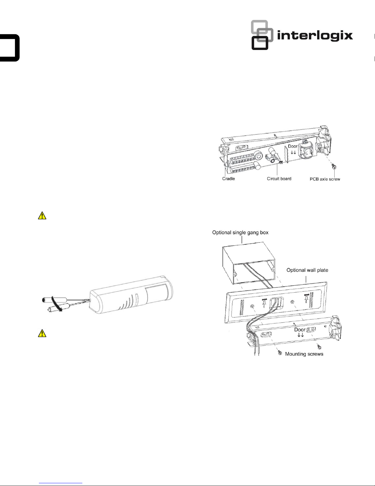
Figure 2: Remove the circuit board and cradle
Determine if the sensor will be ceiling or wall mounted. Avoid
locating the sensor between double doorways where objects
can be inserted through a crack to gain unauthorized entry.
CAUTION: When handling the sensor, do not touch the lens
window.
To install the sensor, do the following:
1. To open the front cover, insert a small screwdriver into
the bottom of the locking tab and pull upward (Figure 1).
Figure 1: Open the cover
CAUTION: You must be free of static electricity before handling
sensor circuit boards. Touch a grounded, bare metal
surface before touching circuit boards or wear a
grounding strap.
2. Remove the screw holding the circuit board (PCB)
cradle axle to the back housing and carefully remove
the circuit board with cradle from the housing (Figure 2).
3. Route wiring to the sensor mounting location. If you are
using the wall plate, pull the wires through the cable
entry hole (Figure 3).
Figure 3: Mounting and wiring access
4. Insert the mounting screws into the back (wall mount) or
top (ceiling mount) mounting screw holes to fasten the
back housing and wall plate, if used, to the wall or
ceiling (Figure 3).
5. Reinstall the PCB/cradle and secure in place with the
PCB axle screw (Figure 2).
6. Complete wiring connection (See Wiring on page 2).
7. Swing the front cover in place and walk test the sensor
for appropriate coverage and function (see Initial power
up on page 4.
© 2018 UTC Fire & Security. All rights reserved. 1 / 7 P/N 466-5444 • REV A • 8NOV18
Wiring
This section provides examples of different wiring options.
The options are all shown in the failsafe mode.
Note: Failure to spike protect the sensor may result in shortening
the life of the relay contacts.
RCR-REX and a Keycard Reader
Basic Hook-up
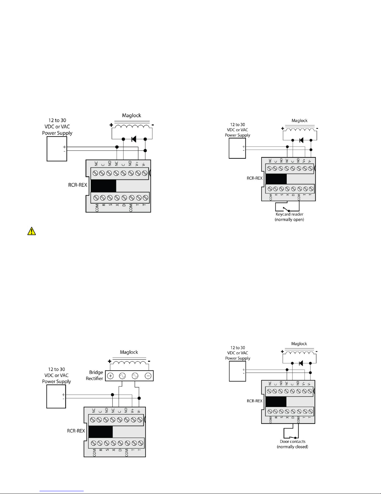
Figure 4 shows the basic hook-up for the RCR-REX, a
power supply and a magnetic lock. When the sensor sees
motion, power is removed from the magnetic lock.
Figure 4: Basic hook-up
CAUTION: For DC powered systems, if the door lock does not
contain a diode across the coil winding, install a diode
across the door lock to prevent degradation of the lock
relay contacts. The diode should have a current rating
greater than the maximum lock current. Install the
diode so that the cathode end with the bar is
connected to the positive side of the coil.
Spike Protection
Many magnetic locks and electric door strikes have built in
spike (diode) protection. If the lock is not spike protected,
install a bridge rectifier, such as a KBL005, between the
relay contacts and the magnetic lock/door strike as shown in
Figure 5.
Figure 5: Spike Protection
Figure 6 shows the wiring normally used when a keycard
reader is on one side of the door and the RCR-REX is on the
other side of the door. Both swiping a keycard or the
detection of motion by the RCR-REX will remove power from
the magnetic lock.
Figure 6: RCR-REX and a keycard reader
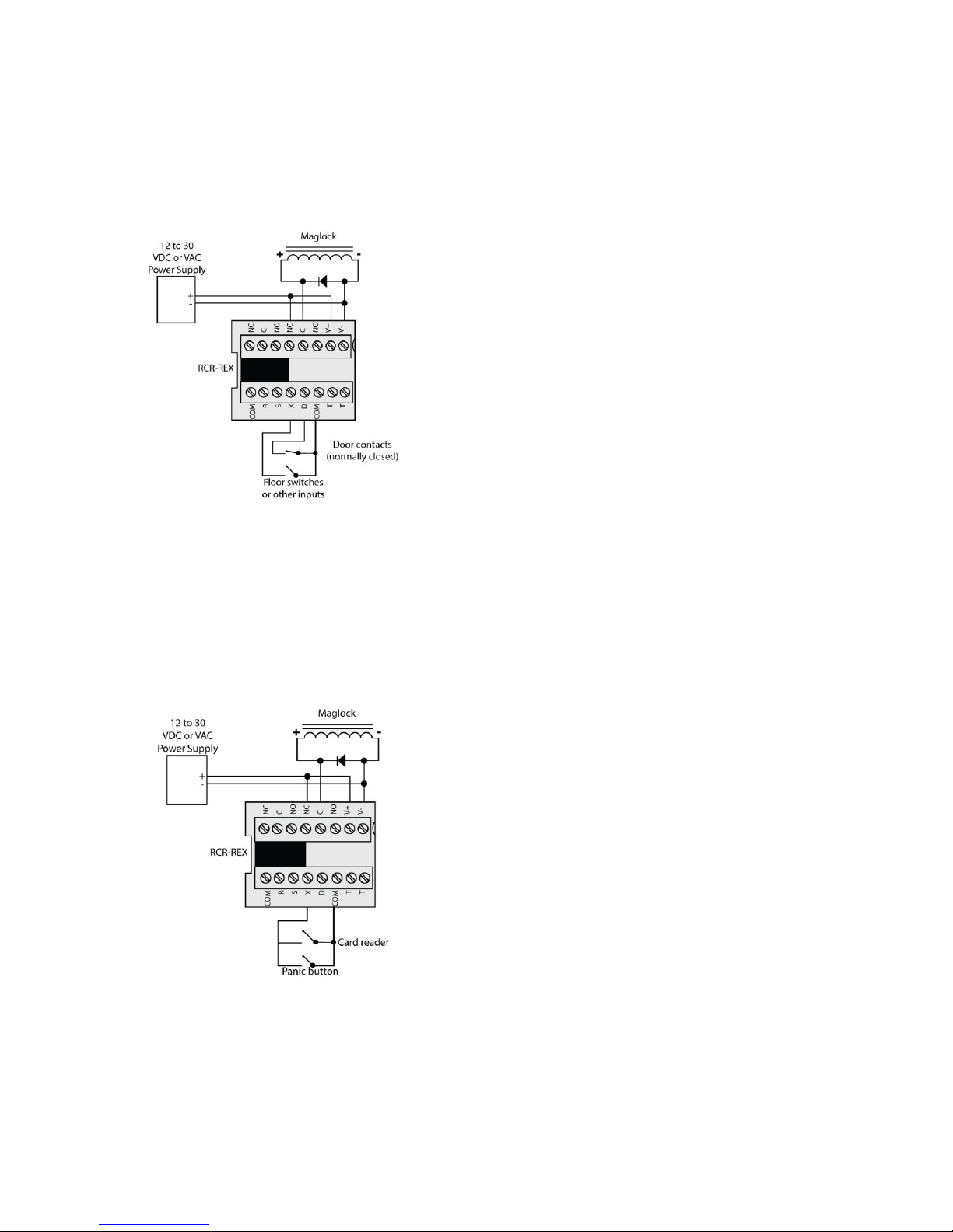
Monitor Door Contacts (first option)
In the monitor door contacts mode, a person entering the
sensor’s field of view will activate the relay and timer. Door
contacts connected to terminal D will monitor if the door is
open or closed. If the relay timer gets to ten seconds or less
(if set for 16 seconds or greater) and the door is still open,
the RCR-REX internal sounder will activate. The sounder will
also active if the door is opened without first activating the
sensor or keycard input. The sounder will remain on until the
door is closed or by someone moving in the field of view
(Figure 7).
Figure 7: Monitor door contacts (first option)
2 / 7 P/N 466-5444 • REV A • 8NOV18
Monitor Door Contacts (second option)
If the sensor is activated but the door is not opened, the
relay will drop out after ten seconds. If the sensor is
activated and the door is opened, and then closed, the relay
will drop out after two seconds. This prevents unauthorized
people from entering (Figure 8).
Figure 8: Monitor door contacts (second option)
R (input) Arm
This pin is used to enable and disable the unit with an
external signal. The unit will be disabled when R is grounded
for more than 10 seconds. Thereafter, when R is
ungrounded, the unit will be enabled. Motion detected by the
unit up to 10 seconds after R is grounded and at least 100
milliseconds after R is ungrounded will start the relay timer.
This pin must be switched with a dry contact or an open
collector transistor referenced to COM (ground).
S (input) Sounder
This pin allows external control of the sounder that takes
precedence over all other sounder modes. If the unit is
powered up with S ungrounded, then the unit assumes that
S is unused.
Whenever S is grounded after power up, the unit assumes
that S is being used to externally activate the sounder.
Thereafter, when S is ungrounded for at least 100
milliseconds, the sounder will unconditionally turn on and
stay on until S is grounded.
Panic Button
Many fire codes require a panic button to be part of the
installation. The RCR-REX has an X (external) input (see X
(input) external) for a normally open panic button or an
internal timer panic button. When X input is grounded, the
door will open. Two normally open devices may be
connected to the X input (Figure 9).
Figure 9: Panic Button
NC, C, NO (I/O) Monitor Relay Section
Connect the monitor relay terminals across the normally
closed contacts (NC) of the door switch and across the
access control system. If there is no access control system,
connect the normally closed contacts of the door switch
across the monitor relay terminals.
This pin must be switched with a dry contact or an open
collector transistor referenced to COM (ground).
X (input) External
This pin can be used by card readers, keypads, remote push
buttons, and key locks to cause the sensor to start a timing
cycle.
If X is pulled to ground for at least 500 milliseconds and less
than 3 seconds, the lock/monitor relay will unlock the door
and the lock timer will start as if a person walked into the
detection area. If X is grounded for more than 3 seconds,
then the relay will stay in the unlocked state until X is
allowed to go high. When X goes high and if the door is still
open, the sounder will produce a beeping tone and the relay
will remain in the unlocked state until the door closes. When
the door closes, the relay will lock the door and shunt the
door switch.
This pin must be switched with a dry contact or an open
collector transistor referenced to COM (ground).
D (input) Door
This pin is used to detect the state of the door switch. The
door switch must be connected between pins D and COM
(ground). If the unit is powered up with D ungrounded, the
unit assumes that D is unused. If D is ever grounded after
the unit is powered up, the unit assumes that D is being
used to sense door position and the sounder will beep (if
enabled) when the door is left open.
If used, this pin must be switched with a dry contact or an
open collector transistor referenced to COM (ground). See
S2-7 (door monitor mode) on page 4.
P/N 466-5444 • REV A • 8NOV18 3 / 7
 Loading...