

Interlogix ATS1500A-SM, ATS1500A-LP, ATS1500A-MM, ATS3500A-MM, ATS1500A-IP-LP Installation And Programming Manual
...
Advisor Advanced
ATSx500A(-IP) Installation
and Programming Manual
P/N 466-2576 (EN) • REV B • ISS 16SEP16

Copyright
© 16SEP16 UTC Fire & Security Americas Corporation, Inc. All
rights reserved.
Trademarks and
patents
Interlogix, Advisor Advanced ATSx500A(-IP) name and logo are
trademarks of UTC Fire & Security.
Other trade names used in this document may be trademarks or
registered trademarks of the manufacturers or vendors of the
respective products.
Manufacturer
UTC Fire & Security Americas Corporation, Inc.
3211 Progress Drive, Lincolnton, NC, 28092, USA
Authorized EU manufacturing representative:
UTC Fire & Security B.V.
Kelvinstraat 7, 6003 DH Weert, Netherlands
Version
This document applies to the following Advisor Advanced firmware
versions:
ATSx500A(-IP): MR_3.0
Certification
EN 50131-1 System requirements
EN 50131-3 Control and indicating equipment
EN 50131-6 Power Supplies
EN 50136-1-1 Alarm systems -Alarm Transmission systems
ATS1500A(-IP): Security Grade 2, Environmental class II
ATS3500A(-IP): Security Grade 3, Environmental class II
ATS4500A-IP: Security Grade 3, Environmental class II
Note: ATS1500A(-IP) is upgradable to Security Grade 3 using the
ATS-MM-TK (MM enclosure) or the ATS-SM-TK (SM enclosure)
tamper kit.
Tested and certified by VdS Schadenverhütung GmbH
Important: To comply with the above standards, it is required to
configure the system according to settings listed in Chapter 8
“Regulations” on page 301 onwards.
This product has not been designed to comply with EN 50134 and
EN 54 norms.
European Union
directives
UTC Fire & Security hereby declares that this device is in
compliance with the applicable requirements and provisions of one
or more of the Directives 2014/30/EU and 2014/35/EU. For more
information see www.utcfireandsecurity.com or www.interlogix.com.
2002/96/EC (WEEE directive): Products marked with this symbol
cannot be disposed of as unsorted municipal waste in the European
Union. For proper recycling, return this product to your local supplier
upon the purchase of equivalent new equipment, or dispose of it at
designated collection points. For more information see:
www.utcfssecurityproducts.eu/recycle/
Contact information
www.utcfireandsecurity.com or www.interlogix.com
Customer support
www.utcfssecurityproducts.eu

Content
Important information iii
Chapter 1 Quick installation and programming 1
Quick installation 2
Quick programming 4
Chapter 2 Installation 7
General installation information 8
Maintenance 16
Mounting 18
Earthing 20
Shielding 21
Cabling 22
Configuration 30
Specifications 35
Chapter 3 System functions 41
Function list 43
Zones 45
Areas 50
Set and unset 51
Inhibit and isolate 53
Keys 54
Bus devices 58
Users 60
User groups 62
PIN 66
Outputs 67
Access control 68
Condition filters 74
Triggers 76
Calendar 77
Events 79
Tests and diagnostics 80
Alarm reporting 84
User programmable functions 88
Autoset 91
Wireless device programming 92
Using cameras 98
Engineer reset 102
Timed unset / ATM 103
Chapter 4 Programming 105
The Advisor Advanced menu 106
Advisor Advanced ATSx500A(-IP) Installation and Programming Manual i

How to program the options 108
Remote access 113
Initial start-up 114
Chapter 5 Menu reference 117
1 Service menu 120
2 Device menu 142
3 User menu 162
4 Zones and areas 171
5 Door menu 196
6 Outputs and filters 217
7 Calendar 225
8 System option menu 232
9 Dialler menu 258
Chapter 6 Software 287
Programming Advisor Advanced via configuration software 288
Upgrading Advisor Advanced firmware 290
Chapter 7 Troubleshooting 295
Recovery procedure 296
Device troubleshooting 297
Chapter 8 Regulations 301
Options affected by EN 50131 regulations 302
Options affected by other regulations 308
Appendix A Advisor Advanced events 311
Appendix B Advisor Advanced reporting codes 327
Glossary 337
Index 343
Programming map 351
ii Advisor Advanced ATSx500A(-IP) Installation and Programming Manual

Model
Enclosure
Dimensions (mm)
Weight (kg)
ATS1500A-MM
Metal
MM, 315 x 388 x 85
5.2
ATS1500A-IP-MM
Metal
MM, 315 x 388 x 85
5.2
ATS1500A-SM
Metal
SM, 250 x 250 x 86
2.8
ATS1500A-IP-SM
Metal
SM, 250 x 250 x 86
2.8
ATS1500A-LP
Plastic
LP, 257 x 400 x 112
2.6
ATS1500A-IP-LP
Plastic
LP, 257 x 400 x 112
2.6
ATS3500A-MM
Metal
MM, 315 x 388 x 85
5.2
ATS3500A-IP-MM
Metal
MM, 315 x 388 x 85
5.2
ATS3500A-LP
Plastic
LP, 257 x 400 x 112
2.6
ATS3500A-IP-LP
Plastic
LP, 257 x 400 x 112
2.6
ATS4500A-IP-MM
Metal
MM+, 315 x 445 x 88
5.4
ATS4500A-IP-LM
Metal
LM, 475 x 460 x 160
10.9
Important information
This document includes an overview of the product and detailed instructions
explaining how to install your Advisor Advanced system and program it.
To use this document effectively, you should have the following minimum
qualifications:
• Basic knowledge of alarm systems and components
• Basic knowledge of electrical wiring and low-voltage electrical connections
Read these instructions and all ancillary documentation entirely before installing
or operating this product.
Important note
This manual provides information for all Advisor Advanced and Advisor
Advanced-IP control panels in all variations. “Advisor Advanced control panel”
refers to any variant of the Advisor Advanced control panels, unless specifically
stated otherwise.
List of panel variants
Table 1: List of ATSx500A(-IP) panel variants
Notes
• Not all variants may be available.
• Weight does not include batteries.
Advisor Advanced ATSx500A(-IP) Installation and Programming Manual iii

Safety sign identifies actions or practices that are required by
EN 60950 Safety Standard.
Limitation of liability
To the maximum extent permitted by applicable law, in no event will UTCFS be
liable for any lost profits or business opportunities, loss of use, business
interruption, loss of data, or any other indirect, special, incidental, or
consequential damages under any theory of liability, whether based in contract,
tort, negligence, product liability, or otherwise. Because some jurisdictions do not
allow the exclusion or limitation of liability for consequential or incidental
damages the preceding limitation may not apply to you. In any event the total
liability of UTCFS shall not exceed the purchase price of the product. The
foregoing limitation will apply to the maximum extent permitted by applicable law,
regardless of whether UTCFS has been advised of the possibility of such
damages and regardless of whether any remedy fails of its essential purpose.
Installation in accordance with this manual, applicable codes, and the instructions
of the authority having jurisdiction is mandatory.
While every precaution has been taken during the preparation of this manual to
ensure the accuracy of its contents, UTCFS assumes no responsibility for errors
or omissions.
Advisory messages
Advisory messages alert you to conditions or practices that can cause unwanted
results. The advisory messages used in this document are shown and described
below.
WARNING: Warning messages advise you of hazards that could result in injury
or loss of life. They tell you which actions to take or to avoid in order to prevent
the injury or loss of life.
Caution: Caution messages advise you of possible equipment damage. They tell
you which actions to take or to avoid in order to prevent the damage.
Note: Note messages advise you of the possible loss of time or effort. They
describe how to avoid the loss. Notes are also used to point out important
information that you should read.
iv Advisor Advanced ATSx500A(-IP) Installation and Programming Manual

Chapter 1
Quick installation and
programming
Summary
The chapter contains basic steps of connection and programming of the Advisor Advanced
control panel and auxiliary devices.
For more detailed description of the installation process, see Chapter 2 “Installation” on page 7.
For details on programming, see Chapter 4 “Programming” on page 105 and Chapter 5 “Menu
reference” on page 117.
Content
Quick installation 2
Quick programming 4
Advisor Advanced ATSx500A(-IP) Installation and Programming Manual 1
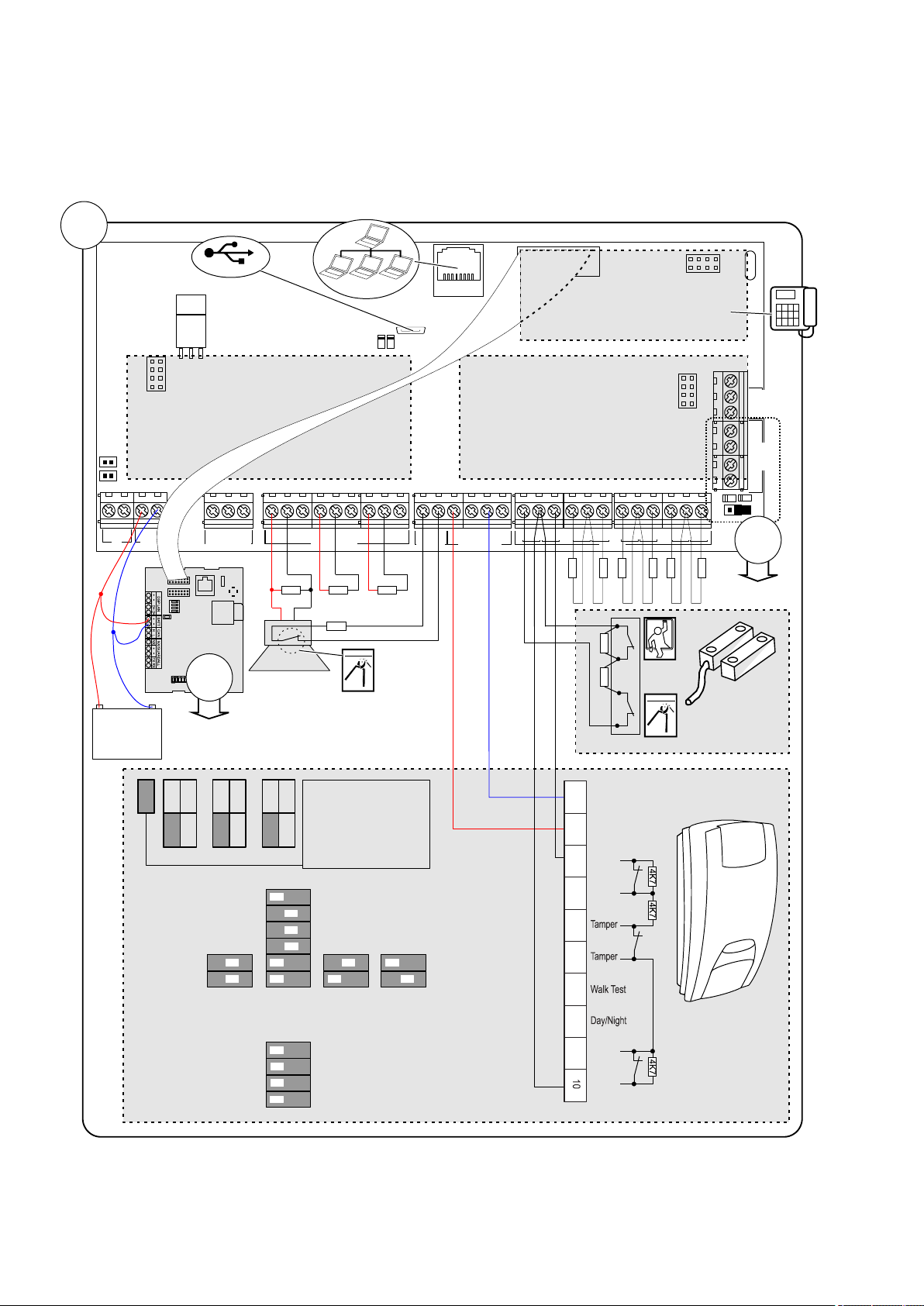
Chapter 1: Quick installation and programming
RxTx
S
Y
S
P
O
L
L
M
I
/
P
A
N
E
L
E
T
H
E
R
N
E
T
S
I
M
G
S
M
G
P
R
S
/
3
G
DGP Addr
1 2 3 4
S
I
M
U
S
B
RxTx
USB
MI
IP
CON12
CON13
T1
T2
S4
S5
+
+
S1
C
+
S2
C
T C
+
+
- -
1 C 2 3 C 4 5 C 6 7 C 8
~~+
-
AC
BATT
LC-OUTPUTS
HC-OUTPUTS
SIR TMP AUX POWER
INPUTS
EARTH
CTD-
D+
0V
+12V
COMMS
TAMPER
+
S3
C
CON16
NTC
ATS7700
ATS608ATS624
ATS626
1K
4K7
4K7
4K7
4K7
4K7
4K7
4K7
+12V
Zone
GND
4K74K7
Zone
GND
DC101
DD1012AM
+ -
TDA74xxNG
1K 1K
2
2
OffOnIsolated fault
contact
3 resistor single
zone
(Terminal 3-10)
=
=
J1
J1
JF JT JA
2 2K
3K
4 7K
1K
2 2K
4 7K
5 6K
1K
2 2K
4 7K
5 6K
1
2
3
4
1
2
1
2
1
2
3
4
5
6
121
2
SW1 - Generic settings
LED ON
Remote OFF
Auto Rem. Test ON
Positive Polarity
LED OFF
Remote ON
Negative Polarity
Range
SW2 - AM/Fault settings
Mask to alarm and
fault relay
Auto reset
Advanced AM sens.
AM Day mode only
Mask to fault relay
only
Authorized reset
Standard AM sens.
AM Day and Night
4
1 .m( 3 ft )
12
40 .m( ft )
9
30 .m( ft )
6
20 .m( ft )
Auto Rem. Test OFF
10K
Zone
J1
1
Alarm
GND
+12V
Fault
Alarm
Fault
1 3 4
5
2 6
7
8 9
Quick installation
2 Advisor Advanced ATSx500A(-IP) Installation and Programming Manual
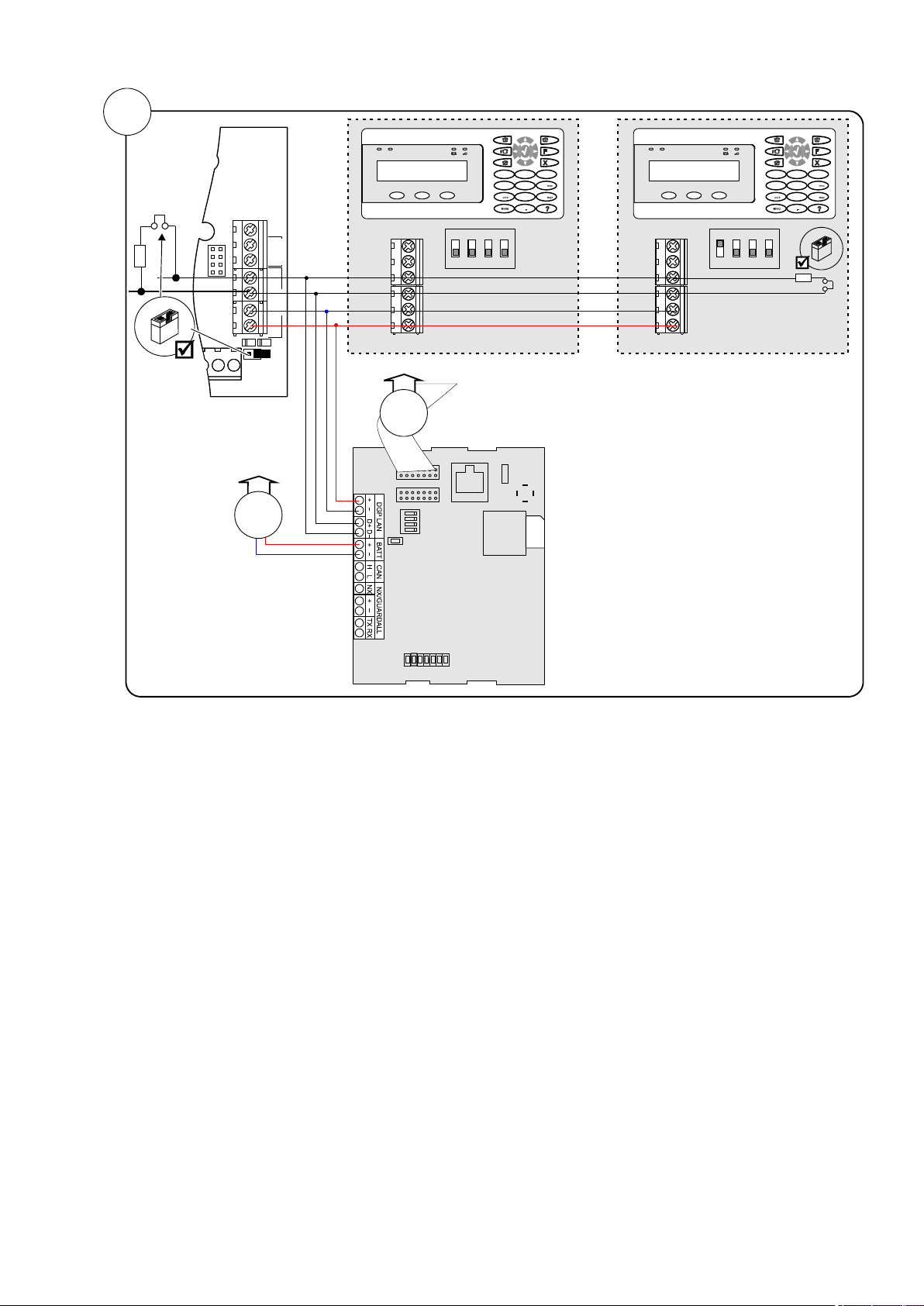
Chapter 1: Quick installation and programming
D+0V+12V D- IN OUT
Rx
Tx
EARTH
CTD-
D+
0V
+12V
COMMS
TAMPER
D+0V+12V D- IN OUT
0
12
3
4
5 6
7 8 9
12
abc
jkl
tuv
def
ghi
.,’?!
*
#
A B C
Address 1
RxTx
S
Y
S
P
O
L
L
M
I
/
P
A
N
E
L
E
T
H
E
R
N
E
T
S
I
M
G
S
M
G
P
R
S
/
3
G
DGP Addr
1 2 3 4
S
I
M
U
S
B
1
1
ATS1135 ATS1135
TDA74xxNG
0
12
3
4
5 6
7 8 9
12
abc
jkl
tuv
def
ghi
.,’?!
*
#
A B C
Address 2
2
Advisor Advanced ATSx500A(-IP) Installation and Programming Manual 3

Chapter 1: Quick installation and programming
Display
Instructions
INFO
Inst required
Press Enter to continue.
1>Panel language
Choose English.
2>Defaults
Choose EN 50131 Grade 3.
4>PIN length
Enter 6.
5>Time&date
Set current time and date.
6 Install
>Cancel<
Choose OK
Installer
PIN:127800
Press Enter to continue.
Supervisor
PIN:112200
Press Enter to continue.
Auto Config?
>Yes<
Press Enter to continue.
Rkp 1-16 BUS1
R-?-------------
Exp 1-15 BUS1
-?-------------
Wait until the panel
configures all bus devices
and zones.
Added
R:1 D:0 Z:8
Press Enter to continue.
UTC F&S
THU 05 Mar 12:21
Press 112200, Menu
1>Zone options
2 Isolate
Go to menu 8.8 Service in
8>Service in
Enable?
Enable Installer in time
UTC F&S
THU 05 Mar 12:21
Press 127800, Menu
Inh reports
>No<
Press Enter to continue.
Inh tampers
Unset areas
1>Service menu
2 Device menu
1>Change PIN
***********
Press Enter.
New PIN
>_
Enter the new installer PIN.
4>Zones&Areas
Press Enter.
1>Zone menu
Press Enter.
0>Add zone
1 Zone 1
Select a zone.
01 Zone name
>1 Zone 1 <
Quick programming
Initial start-up
Note: See “The Advisor Advanced menu”
on page 106 for menu explanation. For
more information on editing options, see
“How to program the options” on page 108.
Switch the panel on. The further messages
and menus are listed in the table below.
Press Cancel, Cancel to log off.
Programming menu entry
The panel restarts.
Auto configuration
The installer menu is displayed.
Changing installer PIN
Go to 3.1.n.2.1 Change PIN (see page 163).
Configuring zones
Go to 4.1 Zone menu (see page 171).
For each zone used in the system, enter
zone name in 4.1.n.1 Zone name (page
172).
Enabling service in
Next, set its zone type in 4.1.n.2 Zone type
4 Advisor Advanced ATSx500A(-IP) Installation and Programming Manual
(see page 172).

Chapter 1: Quick installation and programming
02 Zone type
>Entry/Exit 1<
0>Add user
1 Installer
Press Enter to add a user.
INFO
User added
01>User name
User 3
Press Enter.
01 User name
>User 3 <
Enter a new user name.
Lock user data?
>Cancel<
Choose OK and confirm.
1 Area name
>Area 1 <
Enter a new area name
1>PSTN
3 GSM/SMS/GPRS
0>Add CS
1 CS 1
Calling CS 1...
Ready
Adding users
Go to menu 3.1 Users (see page 162).
Configure other options of the user:
• 3.1.n.2 PIN (page 162)
• 3.1.n.3 User card (page 163)
• 3.1.n.6 User groups (page 164), etc.
Repeat for other users.
When leaving the user configuration,
confirm locking the user data.
Select the required path and configure it
depending on the hardware used.
Next, go to menu 9.1 Central station
(page 258).
Add a new CS, or choose an existing one.
Configure the following parameters:
• 9.1.n.1 CS name (page 258)
• 9.1.n.2 Transm path (page 259)
• 9.1.n.3 Protocol (page 259)
• 9.1.n.5 Accounts (page 259)
• Other options, depending on the
communication path used.
Test the communication using menu
1.2.6.n.6 Man. test call (page 131), where
<n> is the number of the configured Central
Station.
Configuring areas
Go to 4.2 Areas (see page 185).
Change the area name in 4.2.n.1 Area
name (see page 185).
Configure other options of the area:
• 4.2.n.2 Exit time (see page 186)
• 4.2.n.3 Entry time (see page 186), etc.
Caution: Before enabling 4.2.n.5.4 Dual
unset (see page 189), make sure to add
users that can assist the unset. See “Adding
users” above.
Configuring Central Station
Regulations
If necessary, follow the instructions given in
Chapter 8 “Regulations” on page 301 to
configure other options, required by the
appropriate standards and norms.
Configure the communication path in 9.3
Path options (page 267).
Advisor Advanced ATSx500A(-IP) Installation and Programming Manual 5

Chapter 1: Quick installation and programming
6 Advisor Advanced ATSx500A(-IP) Installation and Programming Manual

Chapter 2
Installation
Summary
This chapter includes an overview of the product and detailed instructions
explaining how to install the components of your Advisor Advanced system.
Note: A qualified installer, complying with all applicable codes, should perform
whatever hardware installation is required.
Content
General installation information 8
Advisor Advanced housings 8
Advisor Advanced layout 12
Keypads and readers 13
Maintenance 16
Mains power connection 16
Battery replacement 16
Mounting 18
General installation guidelines 18
Earthing 20
Shielding 21
Cabling 22
System databus preferred wiring 22
System databus connection 22
Zone connection 23
Values for end-of-line resistors 24
EOL connection types 27
Siren connection 28
Other connections 28
Configuration 30
Defaulting the panel 30
Zone configuration 30
Outputs 30
Zone and output addressing 31
Specifications 35
Auxiliary current and battery capacity 39
Advisor Advanced ATSx500A(-IP) Installation and Programming Manual 7
Chapter 2: Installation
RxTx
USB
MI
IP
CON12
CON13
T1
T2
S4
S5
+
+
S1
C
+
S2
C
T C
+
+
- -
1 C 2 3 C 4 5 C 6 7 C 8
~
~
+ -
AC
BATT
LC-OUTPUTS
HC-OUTPUTS
SIR TMP AUX POWER
INPUTS
CT
+
S3
C
CON16
NTC
COMMS
+12V0V D+ D-
250
250
9
30
61.5
28.2
37.2
125
9
61.5
126.4
118
Ø20
(2)
()1 ()1
()1
()1 ()1
RxTx
USB
MI
IP
CON12
CON13
T1
T2
S4
S5
+
+
S1 C
+
S2 C
T C
+
+
- -
1 C 2 3 C 4 5 C 6 7 C 8
~
~
+ -
AC
BATT
LC-OUTPUTS
HC-OUTPUTS
SIR TMP AUX POWER
INPUTS
CT
+
S3 C
CON16
NTC
COMMS
+12V0VD+ D-
315
40
385
55
(1)
(1)
(1)
(1)
(1)
(1)
15
104.9
102.5
60
(2)
60
15
24.1
51
35
40
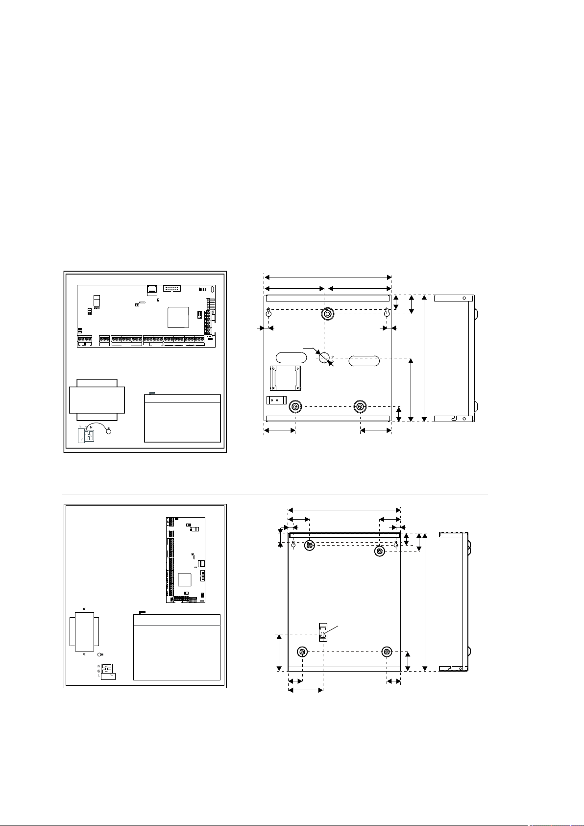
General installation information
Advisor Advanced housings
The housings with mounting holes (items 1) are shown in figures below.
Item 2 indicates the pry-off tamper wall stub location.
All dimensions are given in mm.
Figure 1: Small metal housing (-SM)
Figure 2: Medium metal housing (-MM)
8 Advisor Advanced ATSx500A(-IP) Installation and Programming Manual

Chapter 2: Installation
RxTx
USB
MI
IP
CON12
CON13
T1
T2
S4
S5
+
+
S1
C
+
S2
C
T C
+
+
- -
1 C 2 3 C 4 5 C 6 7 C 8
~
~
+ -
AC
BATT
LC-OUTPUTS
HC-OUTPUTS
SIR TMP AUX POWER
INPUTS
CT
+
S3
C
CON16
NTC
COMMS
+12V0V D+ D-
259
129.5
73
403
54.5
45.5
73
395
50.5
70
126.5
41.5
70
253
()1
()1 ()1
()2
RxTx
USB
MI
IP
CON12
CON13
T1
T2
S4
S5
+
+
S1 C
+
S2 C
T C
+
+
- -
1 C 2 3 C 4 5 C 6 7 C 8
~
~
+ -
AC
BATT
LC-OUTPUTS
HC-OUTPUTS
SIR TMP AUX POWER
INPUTS
CT
+
S3 C
CON16
NTC
COMMS
+12V0VD+ D-
35
315
75
31
33
24
460
35
92.5
157.5157.5
()1 ()1 ()1
()1
()1
()2
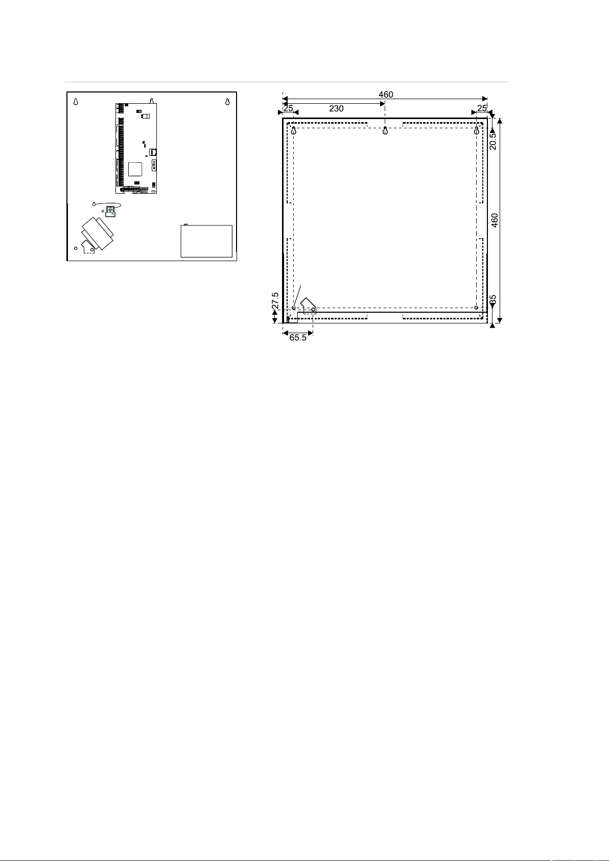
Figure 3: Large polycarbonate housing (-LP)
Figure 4: Medium metal housing (-MM+)
Advisor Advanced ATSx500A(-IP) Installation and Programming Manual 9
Chapter 2: Installation
N
N
RxTx
USB
MI
IP
CON12
CON13
T1
T2
S4 S5
+
+
S1 C
+
S2 C
T C
+
+
- -
1 C 2 3 C 4 5 C 6 7 C 8
~
~
+ -
AC
BATT
LC-OUTPUTS
HC-OUTPUTS
SIR TMP AUX POWER
INPUTS
CT
+
S3 C
CON16
NTC
COMMS
+12V0VD+ D-
()1()1 ()1
()1
()1
()2
Figure 5: Large metal housing (-LM)
For more details on connections and connecting devices to the Advisor
Advanced, see “Cabling” on page 22.
For details on connecting pry-off tampers, see “Pry-off tamper mounting” below.
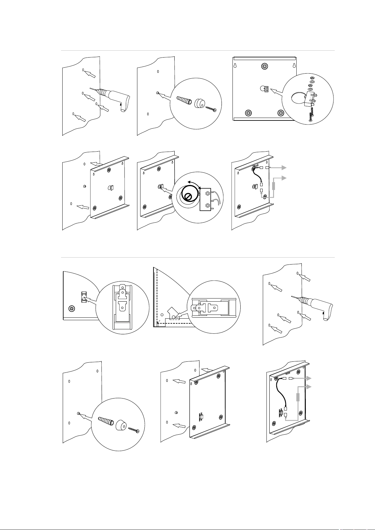
Pry-off tamper mounting
For small housing (SM), follow the steps in Figure 6 on page 11 to install pry-off
tamper. For medium (MM and MM+), and large housings (LM), follow the steps in
Figure 7 on page 11. For large plastic housing (LP), follow the steps in Figure 8
on page 12.
10 Advisor Advanced ATSx500A(-IP) Installation and Programming Manual
Chapter 2: Installation
COM
NO
COM
NO
C
T
TAMPER
A B C
D E F
COM NO
COM
NO
C
T
TAMPER
B
C
D E
A
MM, MM+ LM
Figure 6: Small housing (SM) pry-off tamper mount
Figure 7: Medium (MM and MM+) and large housing (LM) pry-off tamper mount
Advisor Advanced ATSx500A(-IP) Installation and Programming Manual 11

Chapter 2: Installation
(1) Interface to output expander
(2) USB fault LED
(3) USB power LED
(4) USB connector (micro-A/B type)
(5) Ethernet RJ-45 connector (ATS-IP only)
(6) IP communication LED (ATS-IP only)
(7) Heartbeat LED
(8) MI-bus connector for MI devices
(9) Interface to input expander
(10) Interface to PSTN module
(11) Optional: enclosure ambient temperature
sensor
(12) ATS670 databus expander connector
(13) Panel earth terminal
(14) External tamper switch
(15) RS-485 system databus connections
(16) T2: Device firmware upgrade mode
(DFU)
(17) RS-485 system databus communication
LEDs
(18) T1: Restores installer default PIN
(19) System databus termination jumper
(20) AC power supply terminal
(21) Battery connection
(22) Low current (OC) outputs
(23) High current outputs
(24) Siren tamper switch
(25) 12 VDC auxiliary power output
(26) Zone inputs
B
A
()1 ()2 ()3 ()5 ()6 (10)(9)
(22)
(21)
(23)
(18)
(16)
(24) (25)
(19)
(17)
(15)
(14)
(26)
()4 (11)
(13)
RxTx
USB
MI
IP
CON12
CON13
T1
T2
S4
S5
+
+
S1
C
+
S2
C
T C
+
+
- -
1 C 2 3 C 4 5 C 6 7 C 8
~
~
+ -
AC
BATT
LC-OUTPUTS
HC-OUTPUTS
SIR TMP AUX POWER
INPUTS
CT
+
S3
C
CON16
NTC
COMMS
+12V 0VD+ D-
(12)
(20)
(8)
(7)
Figure 8: Large plastic housing (LP) pry-off tamper mount
Advisor Advanced layout
Figure 9: Advisor Advanced ATSx500A(-IP) PCB layout
12 Advisor Advanced ATSx500A(-IP) Installation and Programming Manual

Chapter 2: Installation
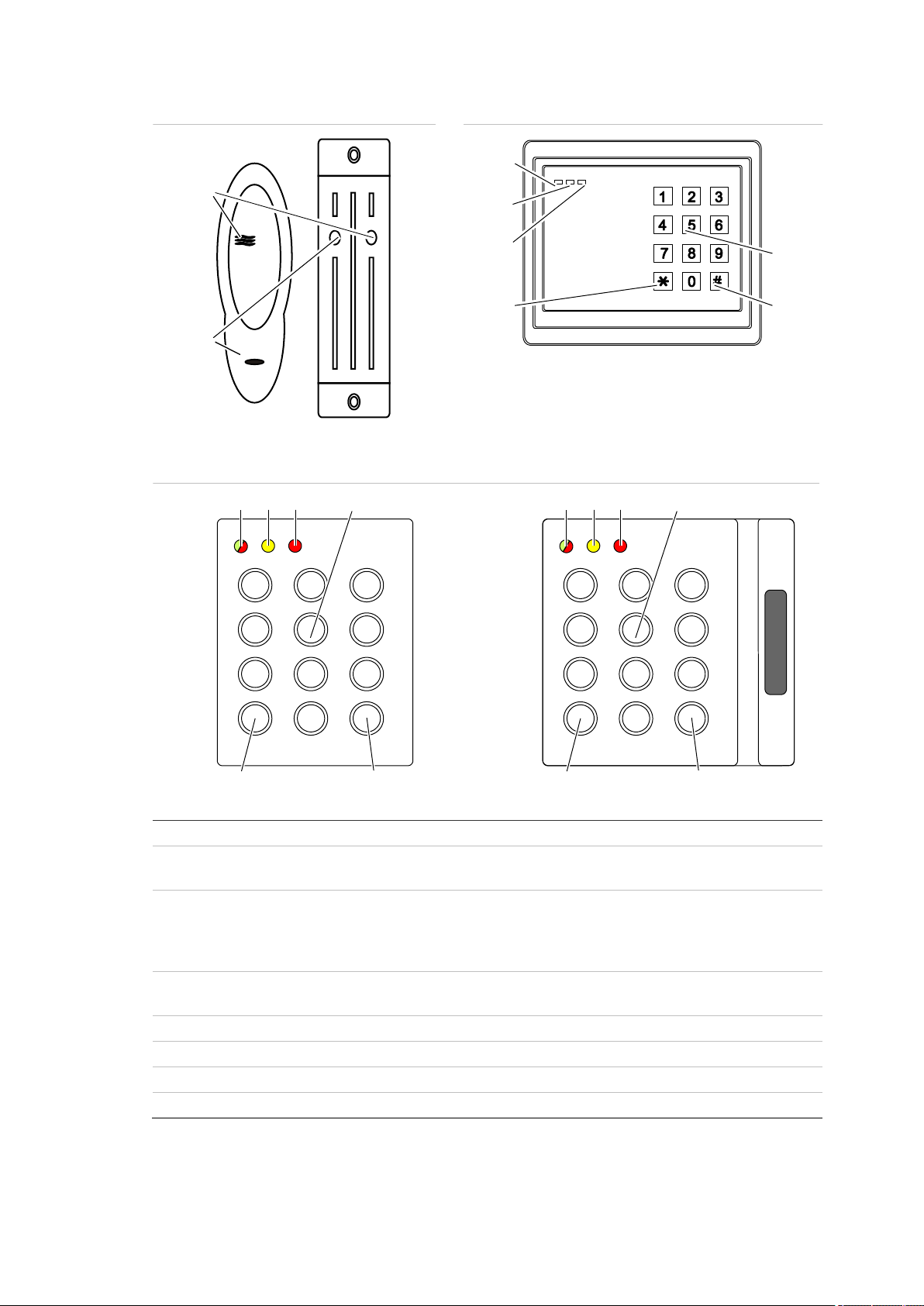
Figure 10: ATS111xA keypad
Figure 11: ATS1135 keypad
(1)
AC mains LED
Green on: AC mains supply on
(2)
Access LED
Blue flashes: card read
(3)
Fault LED
Yellow on: system fault active
Yellow flashing: general alert (EN 50131)
(4)
Alarm LED
Red on: alarm condition active
(5)
LCD display
Displays messages
(6)
/ Up
Scroll up in the menus
Change value
Delete
(7)
? / Help
Show help
Scroll text (ATS113x only)
(8)
Partset
Part set an area
Scroll text (ATS111x only)
(9)
F / Function
Show active zones / faults
Function key modifier
Scroll text (ATS113x only)
(10)
On
Full set an area
(11)
/ Right
Enter the selected menu
Move cursor right
(12)
/ Left
Return to the previous menu
Move cursor left
(13)
X / Clear
Exit the current user function
Volume control modifier
(14)
Off
Unset an area
1
8
9
16
!!
3
21
4 6
5
7
98
0
*
Menu
#
Enter
(1) (2)
(3)
(4)
(5)
(7)
(8)
(9)
(10)
(20)
(19)
(18)
(17)
(16)
(15)
(14)
(13)
(12)
(11)
(6)
0
12
3
4
5
6
789
12
abc
jkl
tuv
def
ghi
.,’?!
*
#
A B C
(1) (3) (6) (4) (2)
(14)
(10)
(21)
(12)
(6)
(18)
(11)
(22)
(9)
(13)
(23) (16) (17)(15) (19) (7)
(25)
(24)
Keypads and readers
Advisor Advanced ATSx500A(-IP) Installation and Programming Manual 13

Chapter 2: Installation
(15)
/ Down
Scroll down in the menus
Change value
Backspace
(16)
Alphanumeric keys
Keys 1 to 9, alphanumerical data. See “Keypad layout” on page
112.
(17)
Menu
Request entry to the menus
(18)
Enter
Complete the step
Enter the selected menu entry
(19) 0 Key 0
Toggle selection
(20)
Area LEDs 1 to 16
On: area set
Off: area unset
Flashing: area alarm condition
(21)
Partset 1
Part set 1 of areas
(22)
Partset 2
Part set 2 of areas
(23)
A, B, C
Programmable function keys
(24)
LED1
Programmable LED 1
(25)
LED2
Programmable LED 2
14 Advisor Advanced ATSx500A(-IP) Installation and Programming Manual
Chapter 2: Installation
Figure 12: ATS1190/ATS1192 readers
Figure 13: ATS1197 reader with keypad
Figure 14: ATS1151/ATS1156 readers
(1)
Blue LED
Access granted
(2)
Red LED
On: area set
Flashing: general alert (EN 50131)
(3)
Dual LED
Green on: AC mains supply on
Green flashing: AC mains supply off, or unlocked while unset
Red on: all areas set
Red flashing: unlocked while set
(4)
Yellow LED
On: All zones are in normal state
Flashing: general alert (EN 50131)
(5)
Red LED
Flashing: alarm
(6)
Numeric keys
Keys 0 to 9, numerical data
(7)
Off
Unset an area
(8)
On
Full set an area
(1)
(2)
OFF ON
(3)
(4)
(5)
(6)
(7)
(8)
1 2 3
4 5 6
7 8 9
*
0 #
(4) (5) (6)
(7) (8)
(3)
1 2 3
4 5 6
7 8 9
*
0 #
(3) (4) (5) (6)
(7) (8)
Advisor Advanced ATSx500A(-IP) Installation and Programming Manual 15

Chapter 2: Installation
Maintenance
Mains power connection
The intrusion control panel is only allowed to be serviced by dedicated service
personal. The screw of the housing is intended to protect the product from
unintended use.
For metal housing, the screw is already installed out of the box. For plastic
housing, the screw, available inside housing, should be mounted before first time
use.
Use the mains connector terminal for connecting the AC mains supply. A fixed
cable or flexible mains lead to earthed mains outlet can be used. When fixed
wiring is used, insert a dedicated circuit breaker in the power distribution network.
In all cases the mains connection must comply with local regulations.
In case the panel is connected to the power grid using fixed wiring, it is
recommended that earth wire is longer than line and neutral.
Do connect incoming line and neutral to mains connection block according to the
label. This assures that the line will be protected by the mains fuse, and that
service can be done by service personnel.
Make sure that before connecting the mains power, the mains power supply is
disconnected.
When installing the mains power, use strain reliefs such as cable ties and
coupling PG16s to ensure proper wiring. If product entry hole breakouts are
used, it is required to also make use of UL-V2 (or better) approved PG16 cable
gland. Refer to PG16 specification to meet minimum and maximum cable
diameters.
In all cases local regulations must be observed.
WARNING: Electrocution hazard. To avoid personal injury or death from
electrocution, remove all sources of power and allow stored energy to discharge
before installing or removing equipment.
Battery replacement
This product may contain one (or more) sealed, rechargeable, BS-type lead-acid
battery. Because removing a battery may affect the product’s configuration
settings or trigger an alarm, only a qualified installer should remove the batteries.
To remove a battery:
1. Make sure that your product settings allow you to open the cover without
starting the tamper alarm.
2. Switch off the mains power, if necessary, and remove the cover.
16 Advisor Advanced ATSx500A(-IP) Installation and Programming Manual

Chapter 2: Installation
3. Disconnect the battery. Note that depending on the battery model the connectors may be located differently.
4. Remove the battery from the holder.
In case a battery BS131 (12 V / 18 Ah) in an ATS1640 housing is used in
combination with ATS7700 PSTN expander board, it is required to have double
insulation in place. Use adequately insulated wires for PSTN cabling, and make
use of heat shrink.
Dispose of the battery as required by local ordinances or regulations.
See the specifications for your product or contact technical support for
information on replacement batteries.
Advisor Advanced ATSx500A(-IP) Installation and Programming Manual 17

Chapter 2: Installation
Mounting
The unit is mounted with screws or bolts through the mounting holes in the rear
section of the enclosure.
Important: When the product is mounted to the wall, assure that at least
3 times the weight of the product can be supported. The product weight is the
product itself plus battery and accessories.
Ensure that the unit is mounted on a flat, solid, vertical surface such that the
base will not flex or warp when the mounting screws and bolts are tightened.
Leave a 50 mm clearance between equipment enclosures mounted side by side
and 25 mm between the enclosure and the sidewall.
The rechargeable battery must not be fitted until the control panel is secured to
the fixing surface. Under no circumstances should the panel be transported with
a battery fitted.
Take care that wire terminals are isolated. The use of cable ties to neatly secure
cables is recommended.
General installation guidelines
The Advisor Advanced control panels have been designed, assembled, and
tested to meet the requirements of current relevant standards for safety,
emission, and immunity to environmental electrical and electromagnetic
interference.
If the following guidelines are followed, the system will give many years of
reliable service.
In addition to the following guidelines, during the installation of the Advisor
Advanced control panel, it is essential to follow any country-dependent local
standard requirements applicable to the installation. Only a qualified electrician or
other suitably trained and qualified person should attempt to wire this system to
the AC mains or to the public telephone network.
• Ensure that there is a good earth available for the alarm system.
• Maintain a separation between low voltage and mains supply cables. Use
separate points of cable entry to the control panel cabinet.
• If the upper and/or lower cabinet entry cable holes are used to route wiring
into the control panel, always use a proper pipe fitting system by means of an
appropriate conduit and junction box. For this purpose, use only materials of
suitable flammability class (HB or better).
18 Advisor Advanced ATSx500A(-IP) Installation and Programming Manual

Chapter 2: Installation
• For mains power connection, use the mains connector terminal either through
a permanent wiring or a flexible mains cable to an earthed mains outlet.
Always use cable ties to fix the mains cable at the dedicated fixing point
provided near the mains terminal connector.
- When installing permanent, fixed wiring, insert an easily accessible,
dedicated bipolar circuit breaker in the power distribution network.
- Never attempt to solder mains connection wires at the ends where they will
be wired to the terminal connectors.
• Avoid loops of wire inside the control panel cabinet and route cables so that
they do not lie on top or underneath of the printed circuit board. The use of
cable ties is recommended and improves neatness of the wiring within the
box.
• The battery used with this unit, must be made of materials of suitable
flammability class (HB or better).
• Any circuit connected either directly to the onboard relay contacts or to the
external relay contacts through the onboard electronic output must be rated
as a SELV (safety extra-low voltage) operating circuit.
- A mains switching relay must not be fitted inside the control panel cabinet.
- Always place a suppression diode (e.g. a 1N4001) across the relay coil.
- Use only relays with good insulation between the contacts and the coil.
- Maximum cable length for open collector output connection may not exceed
30 m. For longer distances, use relay output expansion (for example, ATS624
four-relay expander).
• The minimum clearance between equipment closures is 50 mm (between
equipment vents).
• Only use these units in a clean environment and not in humid air.
Environmental requirements are given in “Specifications” on page 35.
• For the panel terminal connections, the recommended torque is 0,3 to
0,4 N·m. This torque setting is independent from the AWG (thickness) of the
wires used. A value of 0,4 N·m is also the maximum allowed torque for this
connector.
Advisor Advanced ATSx500A(-IP) Installation and Programming Manual 19

Chapter 2: Installation
Earthing
WARNING: The correct earthing procedures must be followed.
Earthing of one cabinet containing several devices
All devices designed for the system have earth connections via metal studs to
the metal housing. Make sure that these metal studs make good connection to
the housing (beware of paint). The earth connections of every piece of equipment
in the system can be used for connecting the screen of shielded cables.
If a device is placed in a plastic housing the earth lug of the device does not have
to be connected.
Earthing panels in a single building
In one building several cabinets or devices are earthed to a safety ground.
The safety ground for the building must be checked by a licensed contractor.
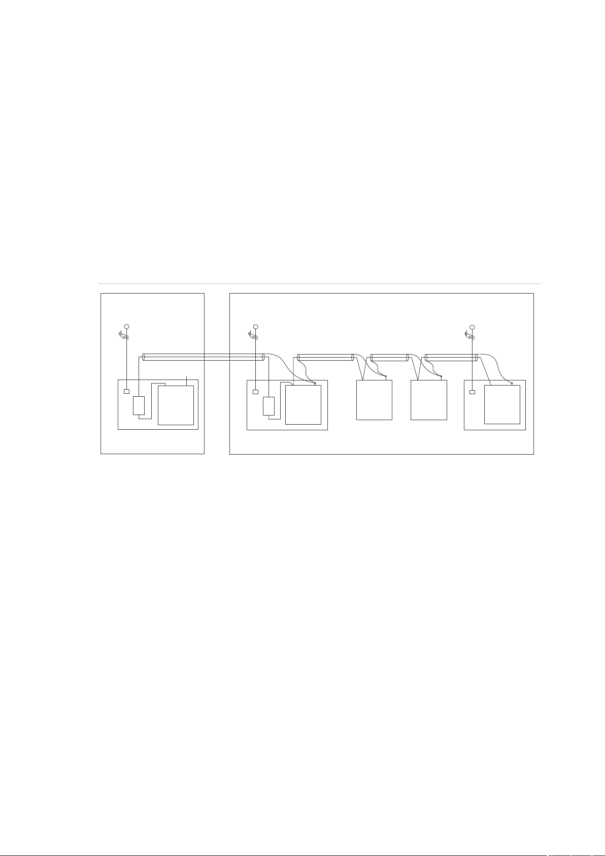
Earthing panels in more buildings
If the wiring extends to separate buildings, more than one common earth system
will be used. Use ATS1740 isolator/repeaters to isolate the system databus. In
this way the system is protected against variations in earth potential.
20 Advisor Advanced ATSx500A(-IP) Installation and Programming Manual
Chapter 2: Installation
(1) Building 1
(2) Building 2
(3) Mains power with local earth
(4) Earth and shielding
(5) Mains power connector
(6) Advisor Advanced control panel
(7) System databus
(8) Device in plastic housing
(9) Device in metal housing
1740
ATS1201(E)
1740
Advisor
Advanced
ATS1210(E)
ATS1135
ATS1203(E)
(1)
(2)
(3)
(4)
(5)
(6)
(7)
(3)
(3)
(4)
(4)
(4)
(4)
(5)
(5)
(7)
(7)
(8)
(9)
(8)
(9)
(9)
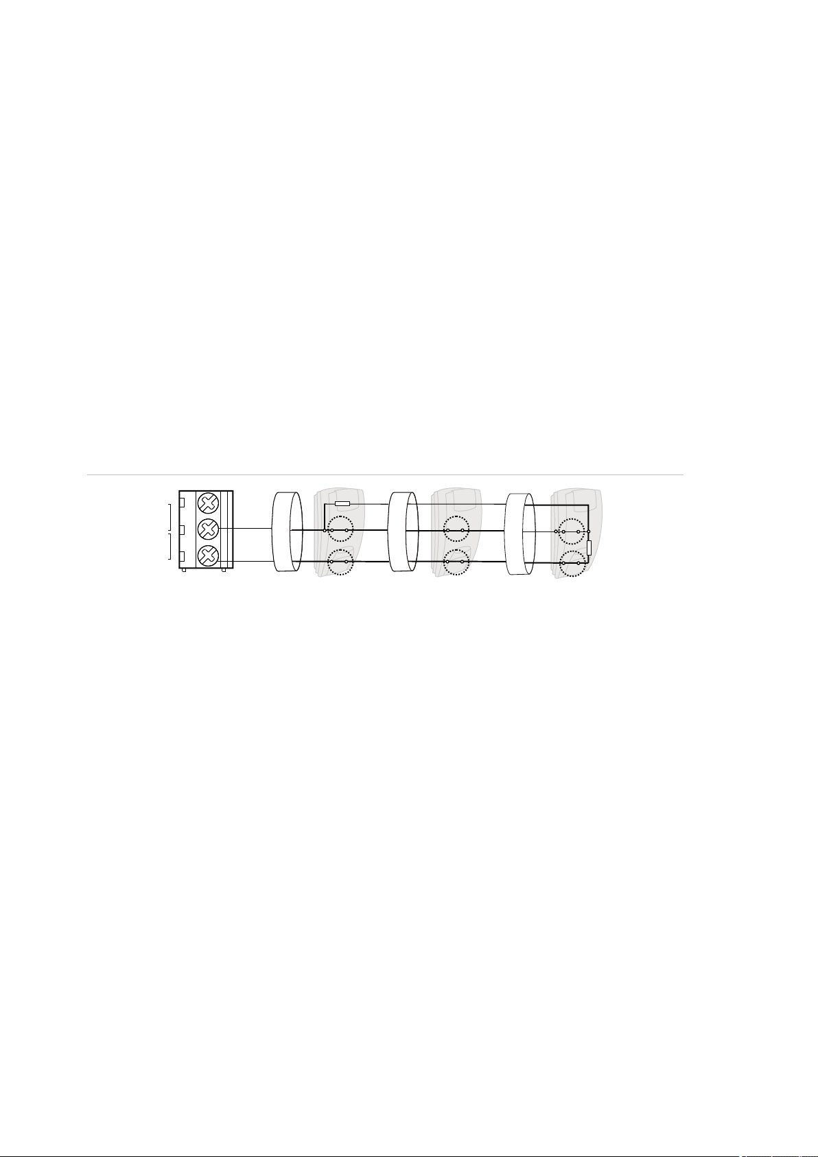
Shielding
The shielding of all shielded cables used in the system should only be connected
at one side to one common earthing point in a building (see Figure 15 below). If a
shielded databus cable is routed via more than one plastic device the shielding
from incoming and outgoing cable must be connected.
In case the IP connection is used, take care that the Ethernet FTP cable remains
within a single building. Do make use of a proper router or switcher to isolate
Ethernet cables between various buildings.
Figure 15: System shielding
Advisor Advanced ATSx500A(-IP) Installation and Programming Manual 21
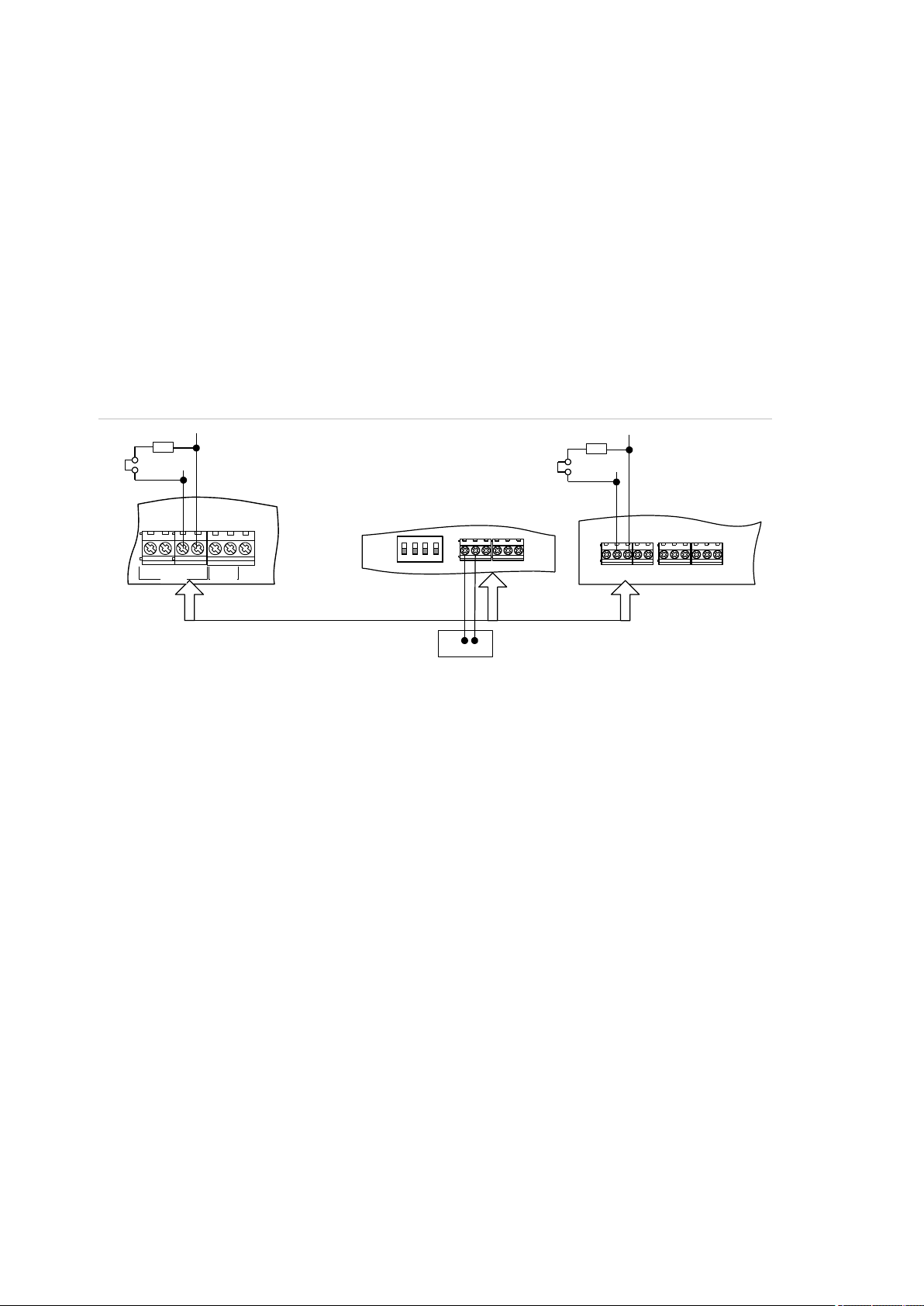
Chapter 2: Installation
(1) TERM link fitted (first device on local
databus).
(2) Advisor Advanced control panel
variants.
(3) Preferred data cable type is WCAT 52
(two twisted pairs).
(4) Advisor LCD keypad (TERM switch is
set to OFF).
(5) Separate 12 V power supply (required if
keypad is more than 100 m from the
nearest panel or expander. Connect the
negative terminal of the power supply to
the “−” wire of the databus.
(6) TERM link fitted (last device on local
databus).
(7) Any remote expander like ATS1201(E) or
ATS1210(E).
D+0V+12V D- IN OUT
CTD-D+
-
1 C 2 C 3 C
470 ohm
+ -
470 ohm
(1)
(2)
(3)
(5)
(4)
(6)
(7)
EARTH
CTD-
D+
0V
12V
COMMS
TAMPER
Cabling
System databus preferred wiring
The terminator jumper (also called TERM link), or DIP switch must be ON, or a
470 Ω resistor must be fitted at each of the devices at the extreme ends of the
daisy chained databus. In a star-wiring configuration, the TERM link is only fitted
on the devices at the ends of the two longest system databus cable runs.
Figure 16: System databus wiring
System databus connection
The system databus is used to connect remote expanders (to provide extra
zones) and keypads to the Advisor Advanced control panel. Remote devices can
be up to 1.5 km from an Advisor Advanced control panel.
Keypads and remote expanders must be connected via a shielded data cable
with two twisted-pairs from the system databus connection (WCAT 52 is
recommended).
We recommend that you use a separate power supply for a keypad when the
distance between that keypad and the nearest device is more than 100 meters.
If the keypad is powered with a separate power supply, do not connect “+” from
the system databus. Connect “+” of the local power supply to “+” on the keypad,
and connect 0 volts from the power supply and 0 volts from the system databus
22 Advisor Advanced ATSx500A(-IP) Installation and Programming Manual

Chapter 2: Installation
C
(1)
T
()2
RA
Z2Z1
A A A
T T
RT
()2 ()2
C
(1)
A
T
()2
RA
Z2Z1
RT
()2 ()2
A
T
A
T
to the keypad terminal marked “−”. The maximum number of devices allowed on
the databus is given in “General features” on page 36.
Two system databuses
Particular panel variants allow you to connect more bus devices by using a
second system databus. To install another system databus, use ATS670 second
RS485 LAN extension module.
System addresses of devices connected to the additional bus (BUS2) are
determined by adding 16 to keypad physical addresses, and 15 to expander
addresses. So, BUS1 handles keypads 1 to 16 and expanders 1 to 15, while
BUS2 — keypads 17 to 32 and expanders 16 to 30.
Note: Door controllers can only be installed on BUS1.
Zone connection
The inputs are set up as standard EOL freely programmable zones. However, by
programming the zones as dual loop, all zone inputs can be programmed to give
a few states indication for the same zone.
Depending on the detector model, do the following to set up zones:
• Choose your EOL connection type. See “EOL connection types” on page 27.
• Program input mode. See “8.6.1 Input mode” on page 248 for the panel, or
“2.2.2.n.4.4 Input mode” on page 152 for expanders.
• Set end-of-line resistor values. See “8.6.2 EOL” on page 248 for the panel, or
“2.2.2.n.4.5 EOL” on page 152 for expanders.
• Configure anti-masking option. See “4.1.n.6.7 Anti mask” on page 175.
Single loop zone wiring
In single loop zone wiring, two zones are required, one zone for alarm and one
zone for tamper. The tamper contacts are wired in series with an EOL resistor.
Figure 17: Single loop examples
Advisor Advanced ATSx500A(-IP) Installation and Programming Manual 23
Chapter 2: Installation
(1) Zone terminal
C Common terminal
Z1 Zone 1 input
Z2 Zone 2 input
(2) Detector
A Alarm relay
T Tamper relay
(1) Zone terminal
C Common terminal
Z1 Zone 1 input
Z2 Zone 2 input
(2) Detector
A Alarm relay
T Tamper relay
C
Z2
(1)
RA
A
()2
RT
T
Z1
A A
T T
()2 ()2
Dual loop zone wiring
In dual loop wiring, one zone can detect a few detector states. At least two
resistors are used to define alarm and tamper states. Depending on the
programmed settings, there can be additional states defined as masking alarm or
sensor fault. These states can be the following:
• Short (tamper)
• Active (alarm)
• Normal
• Masking
• Sensor fault
• Open (tamper)
Figure 18: Dual loop example
Possible EOL connections are listed in “EOL connection types” on page 27.
Values for end-of-line resistors
The following list contains the values for end-of-line resistors and possible zone
states. Both the resistance and the voltage measured across the zone are
shown.
Depending on the input type and anti-masking option, the following EOL values
can be available.
24 Advisor Advanced ATSx500A(-IP) Installation and Programming Manual
 Loading...