

Interlogix ATS1500A-SM, ATS1500A-LP, ATS1500A-MM, ATS3500A-MM, ATS1500A-IP-LP Installation And Programming Manual
...Page 1

Advisor Advanced
ATSx500A(-IP) Installation
and Programming Manual
P/N 466-2576 (EN) • REV B • ISS 16SEP16
Page 2

Copyright
© 16SEP16 UTC Fire & Security Americas Corporation, Inc. All
rights reserved.
Trademarks and
patents
Interlogix, Advisor Advanced ATSx500A(-IP) name and logo are
trademarks of UTC Fire & Security.
Other trade names used in this document may be trademarks or
registered trademarks of the manufacturers or vendors of the
respective products.
Manufacturer
UTC Fire & Security Americas Corporation, Inc.
3211 Progress Drive, Lincolnton, NC, 28092, USA
Authorized EU manufacturing representative:
UTC Fire & Security B.V.
Kelvinstraat 7, 6003 DH Weert, Netherlands
Version
This document applies to the following Advisor Advanced firmware
versions:
ATSx500A(-IP): MR_3.0
Certification
EN 50131-1 System requirements
EN 50131-3 Control and indicating equipment
EN 50131-6 Power Supplies
EN 50136-1-1 Alarm systems -Alarm Transmission systems
ATS1500A(-IP): Security Grade 2, Environmental class II
ATS3500A(-IP): Security Grade 3, Environmental class II
ATS4500A-IP: Security Grade 3, Environmental class II
Note: ATS1500A(-IP) is upgradable to Security Grade 3 using the
ATS-MM-TK (MM enclosure) or the ATS-SM-TK (SM enclosure)
tamper kit.
Tested and certified by VdS Schadenverhütung GmbH
Important: To comply with the above standards, it is required to
configure the system according to settings listed in Chapter 8
“Regulations” on page 301 onwards.
This product has not been designed to comply with EN 50134 and
EN 54 norms.
European Union
directives
UTC Fire & Security hereby declares that this device is in
compliance with the applicable requirements and provisions of one
or more of the Directives 2014/30/EU and 2014/35/EU. For more
information see www.utcfireandsecurity.com or www.interlogix.com.
2002/96/EC (WEEE directive): Products marked with this symbol
cannot be disposed of as unsorted municipal waste in the European
Union. For proper recycling, return this product to your local supplier
upon the purchase of equivalent new equipment, or dispose of it at
designated collection points. For more information see:
www.utcfssecurityproducts.eu/recycle/
Contact information
www.utcfireandsecurity.com or www.interlogix.com
Customer support
www.utcfssecurityproducts.eu
Page 3

Content
Important information iii
Chapter 1 Quick installation and programming 1
Quick installation 2
Quick programming 4
Chapter 2 Installation 7
General installation information 8
Maintenance 16
Mounting 18
Earthing 20
Shielding 21
Cabling 22
Configuration 30
Specifications 35
Chapter 3 System functions 41
Function list 43
Zones 45
Areas 50
Set and unset 51
Inhibit and isolate 53
Keys 54
Bus devices 58
Users 60
User groups 62
PIN 66
Outputs 67
Access control 68
Condition filters 74
Triggers 76
Calendar 77
Events 79
Tests and diagnostics 80
Alarm reporting 84
User programmable functions 88
Autoset 91
Wireless device programming 92
Using cameras 98
Engineer reset 102
Timed unset / ATM 103
Chapter 4 Programming 105
The Advisor Advanced menu 106
Advisor Advanced ATSx500A(-IP) Installation and Programming Manual i
Page 4

How to program the options 108
Remote access 113
Initial start-up 114
Chapter 5 Menu reference 117
1 Service menu 120
2 Device menu 142
3 User menu 162
4 Zones and areas 171
5 Door menu 196
6 Outputs and filters 217
7 Calendar 225
8 System option menu 232
9 Dialler menu 258
Chapter 6 Software 287
Programming Advisor Advanced via configuration software 288
Upgrading Advisor Advanced firmware 290
Chapter 7 Troubleshooting 295
Recovery procedure 296
Device troubleshooting 297
Chapter 8 Regulations 301
Options affected by EN 50131 regulations 302
Options affected by other regulations 308
Appendix A Advisor Advanced events 311
Appendix B Advisor Advanced reporting codes 327
Glossary 337
Index 343
Programming map 351
ii Advisor Advanced ATSx500A(-IP) Installation and Programming Manual
Page 5

Model
Enclosure
Dimensions (mm)
Weight (kg)
ATS1500A-MM
Metal
MM, 315 x 388 x 85
5.2
ATS1500A-IP-MM
Metal
MM, 315 x 388 x 85
5.2
ATS1500A-SM
Metal
SM, 250 x 250 x 86
2.8
ATS1500A-IP-SM
Metal
SM, 250 x 250 x 86
2.8
ATS1500A-LP
Plastic
LP, 257 x 400 x 112
2.6
ATS1500A-IP-LP
Plastic
LP, 257 x 400 x 112
2.6
ATS3500A-MM
Metal
MM, 315 x 388 x 85
5.2
ATS3500A-IP-MM
Metal
MM, 315 x 388 x 85
5.2
ATS3500A-LP
Plastic
LP, 257 x 400 x 112
2.6
ATS3500A-IP-LP
Plastic
LP, 257 x 400 x 112
2.6
ATS4500A-IP-MM
Metal
MM+, 315 x 445 x 88
5.4
ATS4500A-IP-LM
Metal
LM, 475 x 460 x 160
10.9
Important information
This document includes an overview of the product and detailed instructions
explaining how to install your Advisor Advanced system and program it.
To use this document effectively, you should have the following minimum
qualifications:
• Basic knowledge of alarm systems and components
• Basic knowledge of electrical wiring and low-voltage electrical connections
Read these instructions and all ancillary documentation entirely before installing
or operating this product.
Important note
This manual provides information for all Advisor Advanced and Advisor
Advanced-IP control panels in all variations. “Advisor Advanced control panel”
refers to any variant of the Advisor Advanced control panels, unless specifically
stated otherwise.
List of panel variants
Table 1: List of ATSx500A(-IP) panel variants
Notes
• Not all variants may be available.
• Weight does not include batteries.
Advisor Advanced ATSx500A(-IP) Installation and Programming Manual iii
Page 6

Safety sign identifies actions or practices that are required by
EN 60950 Safety Standard.
Limitation of liability
To the maximum extent permitted by applicable law, in no event will UTCFS be
liable for any lost profits or business opportunities, loss of use, business
interruption, loss of data, or any other indirect, special, incidental, or
consequential damages under any theory of liability, whether based in contract,
tort, negligence, product liability, or otherwise. Because some jurisdictions do not
allow the exclusion or limitation of liability for consequential or incidental
damages the preceding limitation may not apply to you. In any event the total
liability of UTCFS shall not exceed the purchase price of the product. The
foregoing limitation will apply to the maximum extent permitted by applicable law,
regardless of whether UTCFS has been advised of the possibility of such
damages and regardless of whether any remedy fails of its essential purpose.
Installation in accordance with this manual, applicable codes, and the instructions
of the authority having jurisdiction is mandatory.
While every precaution has been taken during the preparation of this manual to
ensure the accuracy of its contents, UTCFS assumes no responsibility for errors
or omissions.
Advisory messages
Advisory messages alert you to conditions or practices that can cause unwanted
results. The advisory messages used in this document are shown and described
below.
WARNING: Warning messages advise you of hazards that could result in injury
or loss of life. They tell you which actions to take or to avoid in order to prevent
the injury or loss of life.
Caution: Caution messages advise you of possible equipment damage. They tell
you which actions to take or to avoid in order to prevent the damage.
Note: Note messages advise you of the possible loss of time or effort. They
describe how to avoid the loss. Notes are also used to point out important
information that you should read.
iv Advisor Advanced ATSx500A(-IP) Installation and Programming Manual
Page 7

Chapter 1
Quick installation and
programming
Summary
The chapter contains basic steps of connection and programming of the Advisor Advanced
control panel and auxiliary devices.
For more detailed description of the installation process, see Chapter 2 “Installation” on page 7.
For details on programming, see Chapter 4 “Programming” on page 105 and Chapter 5 “Menu
reference” on page 117.
Content
Quick installation 2
Quick programming 4
Advisor Advanced ATSx500A(-IP) Installation and Programming Manual 1
Page 8
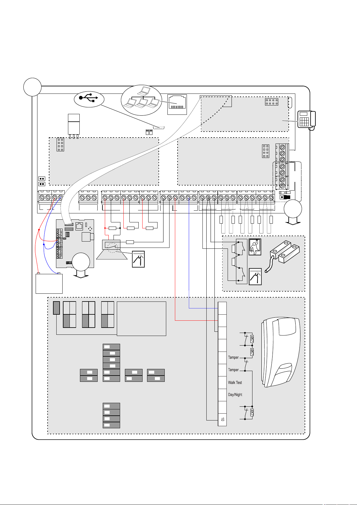
Chapter 1: Quick installation and programming
RxTx
S
Y
S
P
O
L
L
M
I
/
P
A
N
E
L
E
T
H
E
R
N
E
T
S
I
M
G
S
M
G
P
R
S
/
3
G
DGP Addr
1 2 3 4
S
I
M
U
S
B
RxTx
USB
MI
IP
CON12
CON13
T1
T2
S4
S5
+
+
S1
C
+
S2
C
T C
+
+
- -
1 C 2 3 C 4 5 C 6 7 C 8
~~+
-
AC
BATT
LC-OUTPUTS
HC-OUTPUTS
SIR TMP AUX POWER
INPUTS
EARTH
CTD-
D+
0V
+12V
COMMS
TAMPER
+
S3
C
CON16
NTC
ATS7700
ATS608ATS624
ATS626
1K
4K7
4K7
4K7
4K7
4K7
4K7
4K7
+12V
Zone
GND
4K74K7
Zone
GND
DC101
DD1012AM
+ -
TDA74xxNG
1K 1K
2
2
OffOnIsolated fault
contact
3 resistor single
zone
(Terminal 3-10)
=
=
J1
J1
JF JT JA
2 2K
3K
4 7K
1K
2 2K
4 7K
5 6K
1K
2 2K
4 7K
5 6K
1
2
3
4
1
2
1
2
1
2
3
4
5
6
121
2
SW1 - Generic settings
LED ON
Remote OFF
Auto Rem. Test ON
Positive Polarity
LED OFF
Remote ON
Negative Polarity
Range
SW2 - AM/Fault settings
Mask to alarm and
fault relay
Auto reset
Advanced AM sens.
AM Day mode only
Mask to fault relay
only
Authorized reset
Standard AM sens.
AM Day and Night
4
1 .m( 3 ft )
12
40 .m( ft )
9
30 .m( ft )
6
20 .m( ft )
Auto Rem. Test OFF
10K
Zone
J1
1
Alarm
GND
+12V
Fault
Alarm
Fault
1 3 4
5
2 6
7
8 9
Quick installation
2 Advisor Advanced ATSx500A(-IP) Installation and Programming Manual
Page 9
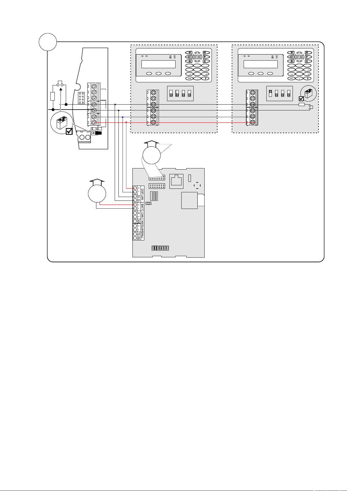
Chapter 1: Quick installation and programming
D+0V+12V D- IN OUT
Rx
Tx
EARTH
CTD-
D+
0V
+12V
COMMS
TAMPER
D+0V+12V D- IN OUT
0
12
3
4
5 6
7 8 9
12
abc
jkl
tuv
def
ghi
.,’?!
*
#
A B C
Address 1
RxTx
S
Y
S
P
O
L
L
M
I
/
P
A
N
E
L
E
T
H
E
R
N
E
T
S
I
M
G
S
M
G
P
R
S
/
3
G
DGP Addr
1 2 3 4
S
I
M
U
S
B
1
1
ATS1135 ATS1135
TDA74xxNG
0
12
3
4
5 6
7 8 9
12
abc
jkl
tuv
def
ghi
.,’?!
*
#
A B C
Address 2
2
Advisor Advanced ATSx500A(-IP) Installation and Programming Manual 3
Page 10

Chapter 1: Quick installation and programming
Display
Instructions
INFO
Inst required
Press Enter to continue.
1>Panel language
Choose English.
2>Defaults
Choose EN 50131 Grade 3.
4>PIN length
Enter 6.
5>Time&date
Set current time and date.
6 Install
>Cancel<
Choose OK
Installer
PIN:127800
Press Enter to continue.
Supervisor
PIN:112200
Press Enter to continue.
Auto Config?
>Yes<
Press Enter to continue.
Rkp 1-16 BUS1
R-?-------------
Exp 1-15 BUS1
-?-------------
Wait until the panel
configures all bus devices
and zones.
Added
R:1 D:0 Z:8
Press Enter to continue.
UTC F&S
THU 05 Mar 12:21
Press 112200, Menu
1>Zone options
2 Isolate
Go to menu 8.8 Service in
8>Service in
Enable?
Enable Installer in time
UTC F&S
THU 05 Mar 12:21
Press 127800, Menu
Inh reports
>No<
Press Enter to continue.
Inh tampers
Unset areas
1>Service menu
2 Device menu
1>Change PIN
***********
Press Enter.
New PIN
>_
Enter the new installer PIN.
4>Zones&Areas
Press Enter.
1>Zone menu
Press Enter.
0>Add zone
1 Zone 1
Select a zone.
01 Zone name
>1 Zone 1 <
Quick programming
Initial start-up
Note: See “The Advisor Advanced menu”
on page 106 for menu explanation. For
more information on editing options, see
“How to program the options” on page 108.
Switch the panel on. The further messages
and menus are listed in the table below.
Press Cancel, Cancel to log off.
Programming menu entry
The panel restarts.
Auto configuration
The installer menu is displayed.
Changing installer PIN
Go to 3.1.n.2.1 Change PIN (see page 163).
Configuring zones
Go to 4.1 Zone menu (see page 171).
For each zone used in the system, enter
zone name in 4.1.n.1 Zone name (page
172).
Enabling service in
Next, set its zone type in 4.1.n.2 Zone type
4 Advisor Advanced ATSx500A(-IP) Installation and Programming Manual
(see page 172).
Page 11

Chapter 1: Quick installation and programming
02 Zone type
>Entry/Exit 1<
0>Add user
1 Installer
Press Enter to add a user.
INFO
User added
01>User name
User 3
Press Enter.
01 User name
>User 3 <
Enter a new user name.
Lock user data?
>Cancel<
Choose OK and confirm.
1 Area name
>Area 1 <
Enter a new area name
1>PSTN
3 GSM/SMS/GPRS
0>Add CS
1 CS 1
Calling CS 1...
Ready
Adding users
Go to menu 3.1 Users (see page 162).
Configure other options of the user:
• 3.1.n.2 PIN (page 162)
• 3.1.n.3 User card (page 163)
• 3.1.n.6 User groups (page 164), etc.
Repeat for other users.
When leaving the user configuration,
confirm locking the user data.
Select the required path and configure it
depending on the hardware used.
Next, go to menu 9.1 Central station
(page 258).
Add a new CS, or choose an existing one.
Configure the following parameters:
• 9.1.n.1 CS name (page 258)
• 9.1.n.2 Transm path (page 259)
• 9.1.n.3 Protocol (page 259)
• 9.1.n.5 Accounts (page 259)
• Other options, depending on the
communication path used.
Test the communication using menu
1.2.6.n.6 Man. test call (page 131), where
<n> is the number of the configured Central
Station.
Configuring areas
Go to 4.2 Areas (see page 185).
Change the area name in 4.2.n.1 Area
name (see page 185).
Configure other options of the area:
• 4.2.n.2 Exit time (see page 186)
• 4.2.n.3 Entry time (see page 186), etc.
Caution: Before enabling 4.2.n.5.4 Dual
unset (see page 189), make sure to add
users that can assist the unset. See “Adding
users” above.
Configuring Central Station
Regulations
If necessary, follow the instructions given in
Chapter 8 “Regulations” on page 301 to
configure other options, required by the
appropriate standards and norms.
Configure the communication path in 9.3
Path options (page 267).
Advisor Advanced ATSx500A(-IP) Installation and Programming Manual 5
Page 12

Chapter 1: Quick installation and programming
6 Advisor Advanced ATSx500A(-IP) Installation and Programming Manual
Page 13

Chapter 2
Installation
Summary
This chapter includes an overview of the product and detailed instructions
explaining how to install the components of your Advisor Advanced system.
Note: A qualified installer, complying with all applicable codes, should perform
whatever hardware installation is required.
Content
General installation information 8
Advisor Advanced housings 8
Advisor Advanced layout 12
Keypads and readers 13
Maintenance 16
Mains power connection 16
Battery replacement 16
Mounting 18
General installation guidelines 18
Earthing 20
Shielding 21
Cabling 22
System databus preferred wiring 22
System databus connection 22
Zone connection 23
Values for end-of-line resistors 24
EOL connection types 27
Siren connection 28
Other connections 28
Configuration 30
Defaulting the panel 30
Zone configuration 30
Outputs 30
Zone and output addressing 31
Specifications 35
Auxiliary current and battery capacity 39
Advisor Advanced ATSx500A(-IP) Installation and Programming Manual 7
Page 14
Chapter 2: Installation
RxTx
USB
MI
IP
CON12
CON13
T1
T2
S4
S5
+
+
S1
C
+
S2
C
T C
+
+
- -
1 C 2 3 C 4 5 C 6 7 C 8
~
~
+ -
AC
BATT
LC-OUTPUTS
HC-OUTPUTS
SIR TMP AUX POWER
INPUTS
CT
+
S3
C
CON16
NTC
COMMS
+12V0V D+ D-
250
250
9
30
61.5
28.2
37.2
125
9
61.5
126.4
118
Ø20
(2)
()1 ()1
()1
()1 ()1
RxTx
USB
MI
IP
CON12
CON13
T1
T2
S4
S5
+
+
S1 C
+
S2 C
T C
+
+
- -
1 C 2 3 C 4 5 C 6 7 C 8
~
~
+ -
AC
BATT
LC-OUTPUTS
HC-OUTPUTS
SIR TMP AUX POWER
INPUTS
CT
+
S3 C
CON16
NTC
COMMS
+12V0VD+ D-
315
40
385
55
(1)
(1)
(1)
(1)
(1)
(1)
15
104.9
102.5
60
(2)
60
15
24.1
51
35
40
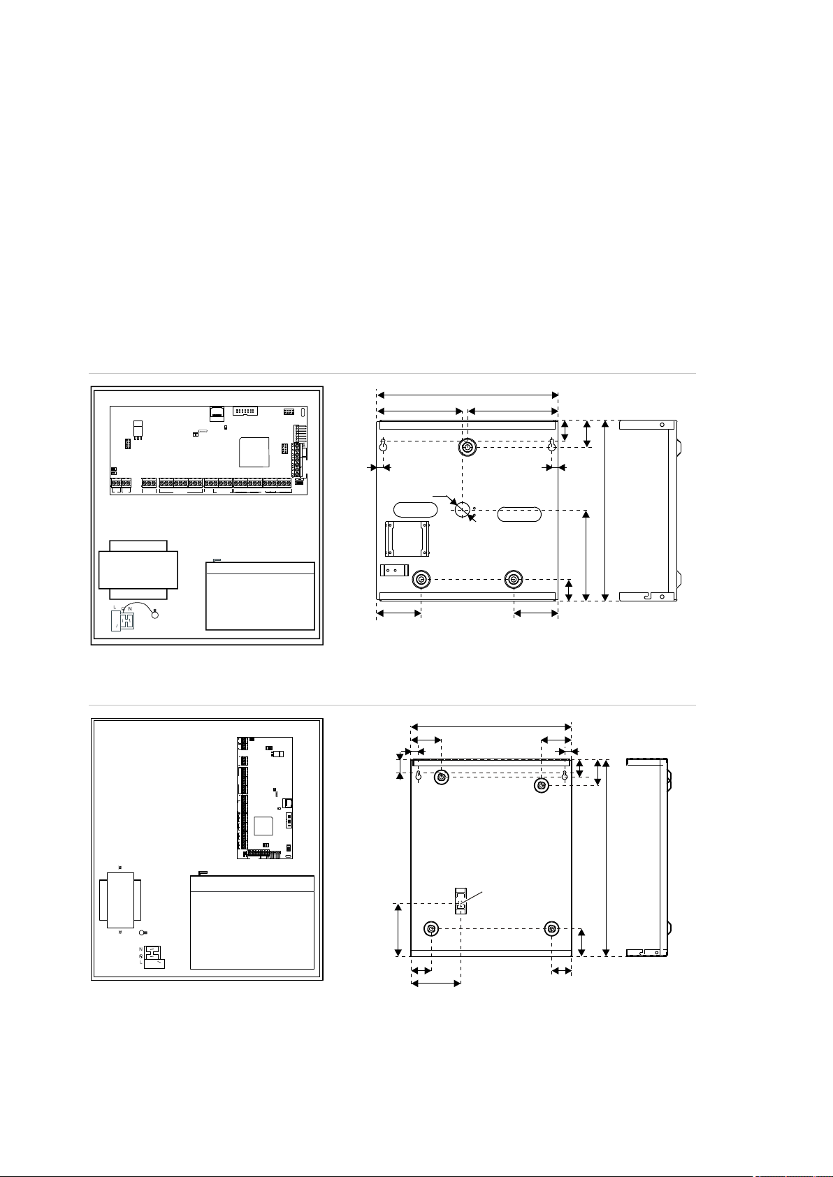
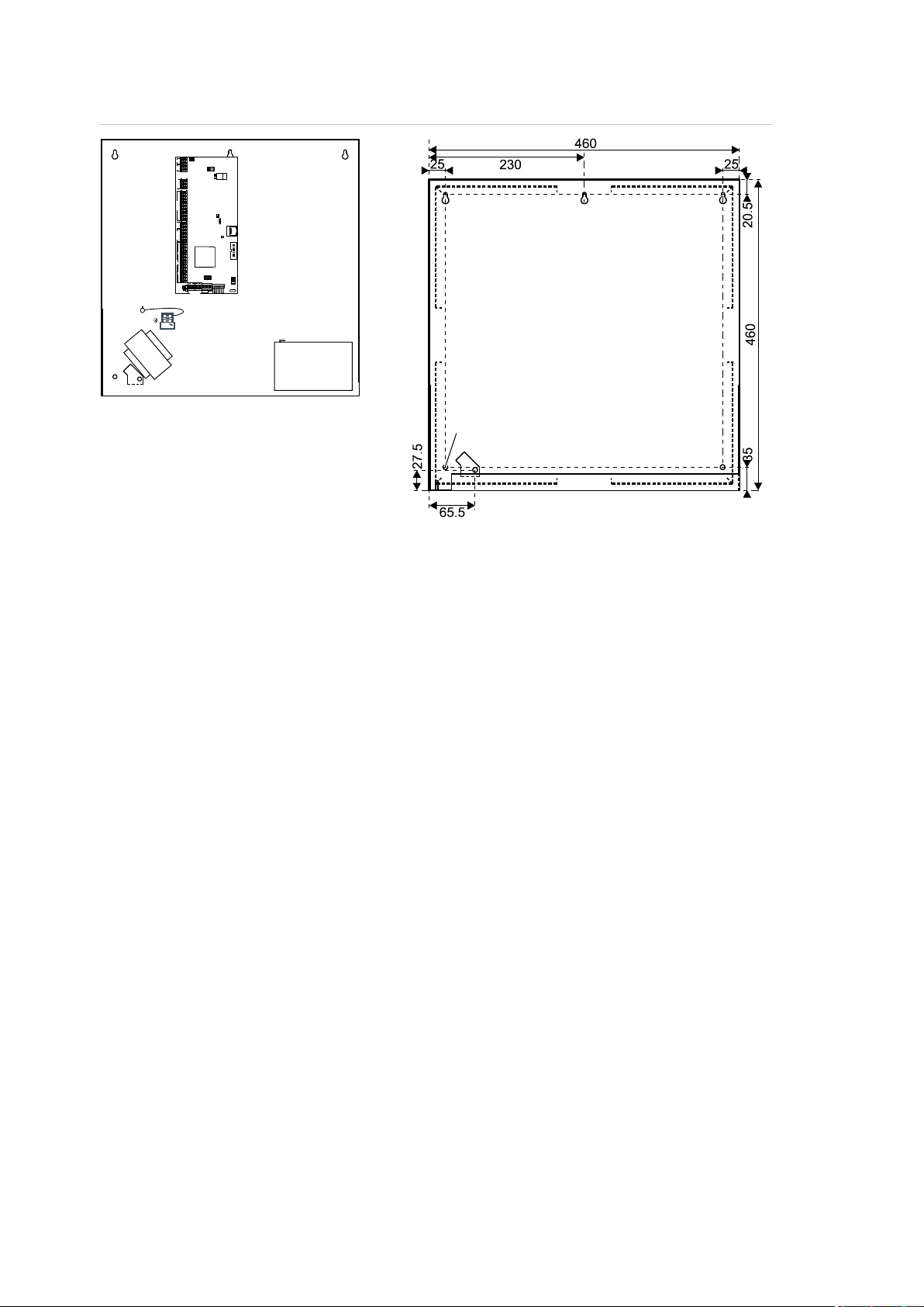
General installation information
Advisor Advanced housings
The housings with mounting holes (items 1) are shown in figures below.
Item 2 indicates the pry-off tamper wall stub location.
All dimensions are given in mm.
Figure 1: Small metal housing (-SM)
Figure 2: Medium metal housing (-MM)
8 Advisor Advanced ATSx500A(-IP) Installation and Programming Manual
Page 15

Chapter 2: Installation
RxTx
USB
MI
IP
CON12
CON13
T1
T2
S4
S5
+
+
S1
C
+
S2
C
T C
+
+
- -
1 C 2 3 C 4 5 C 6 7 C 8
~
~
+ -
AC
BATT
LC-OUTPUTS
HC-OUTPUTS
SIR TMP AUX POWER
INPUTS
CT
+
S3
C
CON16
NTC
COMMS
+12V0V D+ D-
259
129.5
73
403
54.5
45.5
73
395
50.5
70
126.5
41.5
70
253
()1
()1 ()1
()2
RxTx
USB
MI
IP
CON12
CON13
T1
T2
S4
S5
+
+
S1 C
+
S2 C
T C
+
+
- -
1 C 2 3 C 4 5 C 6 7 C 8
~
~
+ -
AC
BATT
LC-OUTPUTS
HC-OUTPUTS
SIR TMP AUX POWER
INPUTS
CT
+
S3 C
CON16
NTC
COMMS
+12V0VD+ D-
35
315
75
31
33
24
460
35
92.5
157.5157.5
()1 ()1 ()1
()1
()1
()2
Figure 3: Large polycarbonate housing (-LP)
Figure 4: Medium metal housing (-MM+)
Advisor Advanced ATSx500A(-IP) Installation and Programming Manual 9
Page 16
Chapter 2: Installation
N
N
RxTx
USB
MI
IP
CON12
CON13
T1
T2
S4 S5
+
+
S1 C
+
S2 C
T C
+
+
- -
1 C 2 3 C 4 5 C 6 7 C 8
~
~
+ -
AC
BATT
LC-OUTPUTS
HC-OUTPUTS
SIR TMP AUX POWER
INPUTS
CT
+
S3 C
CON16
NTC
COMMS
+12V0VD+ D-
()1()1 ()1
()1
()1
()2
Figure 5: Large metal housing (-LM)
For more details on connections and connecting devices to the Advisor
Advanced, see “Cabling” on page 22.
For details on connecting pry-off tampers, see “Pry-off tamper mounting” below.
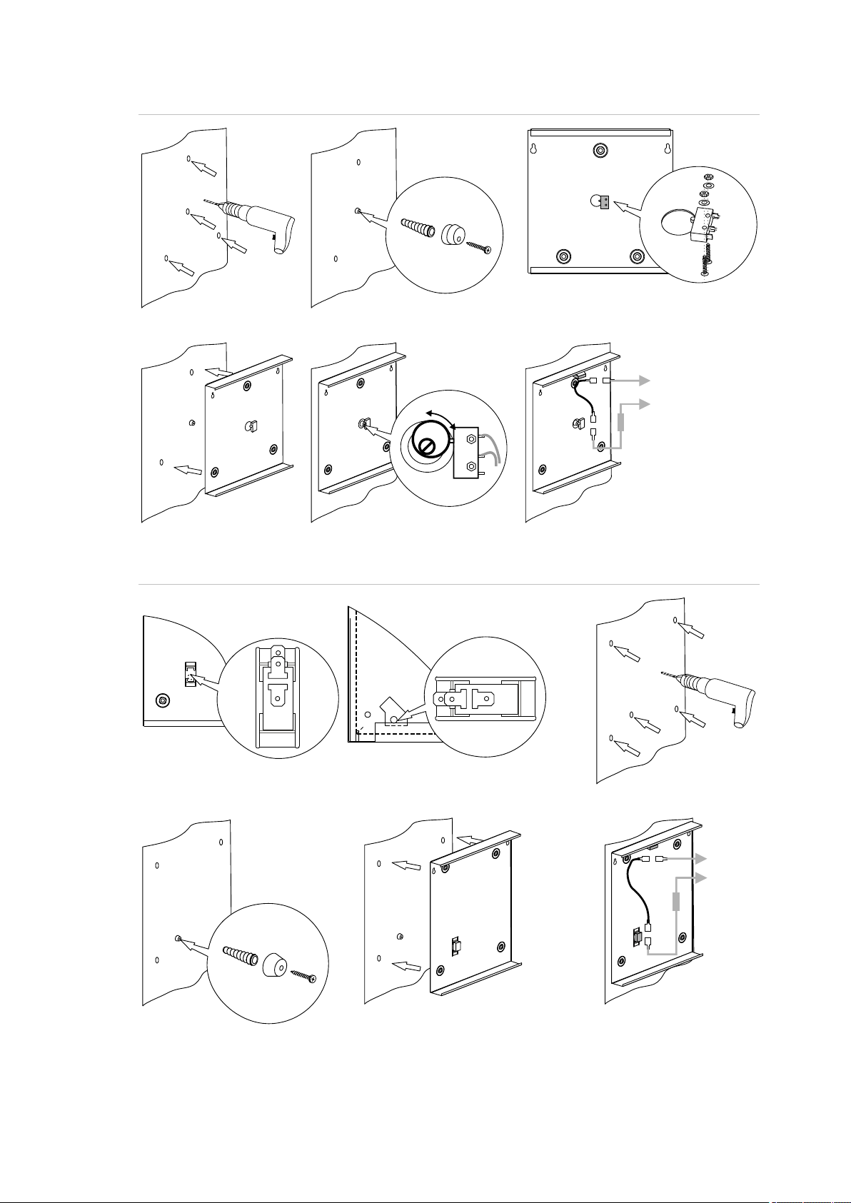
Pry-off tamper mounting
For small housing (SM), follow the steps in Figure 6 on page 11 to install pry-off
tamper. For medium (MM and MM+), and large housings (LM), follow the steps in
Figure 7 on page 11. For large plastic housing (LP), follow the steps in Figure 8
on page 12.
10 Advisor Advanced ATSx500A(-IP) Installation and Programming Manual
Page 17
Chapter 2: Installation
COM
NO
COM
NO
C
T
TAMPER
A B C
D E F
COM NO
COM
NO
C
T
TAMPER
B
C
D E
A
MM, MM+ LM
Figure 6: Small housing (SM) pry-off tamper mount
Figure 7: Medium (MM and MM+) and large housing (LM) pry-off tamper mount
Advisor Advanced ATSx500A(-IP) Installation and Programming Manual 11
Page 18

Chapter 2: Installation
(1) Interface to output expander
(2) USB fault LED
(3) USB power LED
(4) USB connector (micro-A/B type)
(5) Ethernet RJ-45 connector (ATS-IP only)
(6) IP communication LED (ATS-IP only)
(7) Heartbeat LED
(8) MI-bus connector for MI devices
(9) Interface to input expander
(10) Interface to PSTN module
(11) Optional: enclosure ambient temperature
sensor
(12) ATS670 databus expander connector
(13) Panel earth terminal
(14) External tamper switch
(15) RS-485 system databus connections
(16) T2: Device firmware upgrade mode
(DFU)
(17) RS-485 system databus communication
LEDs
(18) T1: Restores installer default PIN
(19) System databus termination jumper
(20) AC power supply terminal
(21) Battery connection
(22) Low current (OC) outputs
(23) High current outputs
(24) Siren tamper switch
(25) 12 VDC auxiliary power output
(26) Zone inputs
B
A
()1 ()2 ()3 ()5 ()6 (10)(9)
(22)
(21)
(23)
(18)
(16)
(24) (25)
(19)
(17)
(15)
(14)
(26)
()4 (11)
(13)
RxTx
USB
MI
IP
CON12
CON13
T1
T2
S4
S5
+
+
S1
C
+
S2
C
T C
+
+
- -
1 C 2 3 C 4 5 C 6 7 C 8
~
~
+ -
AC
BATT
LC-OUTPUTS
HC-OUTPUTS
SIR TMP AUX POWER
INPUTS
CT
+
S3
C
CON16
NTC
COMMS
+12V 0VD+ D-
(12)
(20)
(8)
(7)
Figure 8: Large plastic housing (LP) pry-off tamper mount
Advisor Advanced layout
Figure 9: Advisor Advanced ATSx500A(-IP) PCB layout
12 Advisor Advanced ATSx500A(-IP) Installation and Programming Manual
Page 19

Chapter 2: Installation
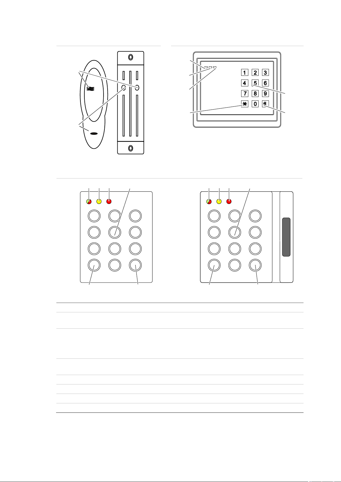
Figure 10: ATS111xA keypad
Figure 11: ATS1135 keypad
(1)
AC mains LED
Green on: AC mains supply on
(2)
Access LED
Blue flashes: card read
(3)
Fault LED
Yellow on: system fault active
Yellow flashing: general alert (EN 50131)
(4)
Alarm LED
Red on: alarm condition active
(5)
LCD display
Displays messages
(6)
/ Up
Scroll up in the menus
Change value
Delete
(7)
? / Help
Show help
Scroll text (ATS113x only)
(8)
Partset
Part set an area
Scroll text (ATS111x only)
(9)
F / Function
Show active zones / faults
Function key modifier
Scroll text (ATS113x only)
(10)
On
Full set an area
(11)
/ Right
Enter the selected menu
Move cursor right
(12)
/ Left
Return to the previous menu
Move cursor left
(13)
X / Clear
Exit the current user function
Volume control modifier
(14)
Off
Unset an area
1
8
9
16
!!
3
21
4 6
5
7
98
0
*
Menu
#
Enter
(1) (2)
(3)
(4)
(5)
(7)
(8)
(9)
(10)
(20)
(19)
(18)
(17)
(16)
(15)
(14)
(13)
(12)
(11)
(6)
0
12
3
4
5
6
789
12
abc
jkl
tuv
def
ghi
.,’?!
*
#
A B C
(1) (3) (6) (4) (2)
(14)
(10)
(21)
(12)
(6)
(18)
(11)
(22)
(9)
(13)
(23) (16) (17)(15) (19) (7)
(25)
(24)
Keypads and readers
Advisor Advanced ATSx500A(-IP) Installation and Programming Manual 13
Page 20

Chapter 2: Installation
(15)
/ Down
Scroll down in the menus
Change value
Backspace
(16)
Alphanumeric keys
Keys 1 to 9, alphanumerical data. See “Keypad layout” on page
112.
(17)
Menu
Request entry to the menus
(18)
Enter
Complete the step
Enter the selected menu entry
(19) 0 Key 0
Toggle selection
(20)
Area LEDs 1 to 16
On: area set
Off: area unset
Flashing: area alarm condition
(21)
Partset 1
Part set 1 of areas
(22)
Partset 2
Part set 2 of areas
(23)
A, B, C
Programmable function keys
(24)
LED1
Programmable LED 1
(25)
LED2
Programmable LED 2
14 Advisor Advanced ATSx500A(-IP) Installation and Programming Manual
Page 21
Chapter 2: Installation
Figure 12: ATS1190/ATS1192 readers
Figure 13: ATS1197 reader with keypad
Figure 14: ATS1151/ATS1156 readers
(1)
Blue LED
Access granted
(2)
Red LED
On: area set
Flashing: general alert (EN 50131)
(3)
Dual LED
Green on: AC mains supply on
Green flashing: AC mains supply off, or unlocked while unset
Red on: all areas set
Red flashing: unlocked while set
(4)
Yellow LED
On: All zones are in normal state
Flashing: general alert (EN 50131)
(5)
Red LED
Flashing: alarm
(6)
Numeric keys
Keys 0 to 9, numerical data
(7)
Off
Unset an area
(8)
On
Full set an area
(1)
(2)
OFF ON
(3)
(4)
(5)
(6)
(7)
(8)
1 2 3
4 5 6
7 8 9
*
0 #
(4) (5) (6)
(7) (8)
(3)
1 2 3
4 5 6
7 8 9
*
0 #
(3) (4) (5) (6)
(7) (8)
Advisor Advanced ATSx500A(-IP) Installation and Programming Manual 15
Page 22

Chapter 2: Installation
Maintenance
Mains power connection
The intrusion control panel is only allowed to be serviced by dedicated service
personal. The screw of the housing is intended to protect the product from
unintended use.
For metal housing, the screw is already installed out of the box. For plastic
housing, the screw, available inside housing, should be mounted before first time
use.
Use the mains connector terminal for connecting the AC mains supply. A fixed
cable or flexible mains lead to earthed mains outlet can be used. When fixed
wiring is used, insert a dedicated circuit breaker in the power distribution network.
In all cases the mains connection must comply with local regulations.
In case the panel is connected to the power grid using fixed wiring, it is
recommended that earth wire is longer than line and neutral.
Do connect incoming line and neutral to mains connection block according to the
label. This assures that the line will be protected by the mains fuse, and that
service can be done by service personnel.
Make sure that before connecting the mains power, the mains power supply is
disconnected.
When installing the mains power, use strain reliefs such as cable ties and
coupling PG16s to ensure proper wiring. If product entry hole breakouts are
used, it is required to also make use of UL-V2 (or better) approved PG16 cable
gland. Refer to PG16 specification to meet minimum and maximum cable
diameters.
In all cases local regulations must be observed.
WARNING: Electrocution hazard. To avoid personal injury or death from
electrocution, remove all sources of power and allow stored energy to discharge
before installing or removing equipment.
Battery replacement
This product may contain one (or more) sealed, rechargeable, BS-type lead-acid
battery. Because removing a battery may affect the product’s configuration
settings or trigger an alarm, only a qualified installer should remove the batteries.
To remove a battery:
1. Make sure that your product settings allow you to open the cover without
starting the tamper alarm.
2. Switch off the mains power, if necessary, and remove the cover.
16 Advisor Advanced ATSx500A(-IP) Installation and Programming Manual
Page 23

Chapter 2: Installation
3. Disconnect the battery. Note that depending on the battery model the connectors may be located differently.
4. Remove the battery from the holder.
In case a battery BS131 (12 V / 18 Ah) in an ATS1640 housing is used in
combination with ATS7700 PSTN expander board, it is required to have double
insulation in place. Use adequately insulated wires for PSTN cabling, and make
use of heat shrink.
Dispose of the battery as required by local ordinances or regulations.
See the specifications for your product or contact technical support for
information on replacement batteries.
Advisor Advanced ATSx500A(-IP) Installation and Programming Manual 17
Page 24

Chapter 2: Installation
Mounting
The unit is mounted with screws or bolts through the mounting holes in the rear
section of the enclosure.
Important: When the product is mounted to the wall, assure that at least
3 times the weight of the product can be supported. The product weight is the
product itself plus battery and accessories.
Ensure that the unit is mounted on a flat, solid, vertical surface such that the
base will not flex or warp when the mounting screws and bolts are tightened.
Leave a 50 mm clearance between equipment enclosures mounted side by side
and 25 mm between the enclosure and the sidewall.
The rechargeable battery must not be fitted until the control panel is secured to
the fixing surface. Under no circumstances should the panel be transported with
a battery fitted.
Take care that wire terminals are isolated. The use of cable ties to neatly secure
cables is recommended.
General installation guidelines
The Advisor Advanced control panels have been designed, assembled, and
tested to meet the requirements of current relevant standards for safety,
emission, and immunity to environmental electrical and electromagnetic
interference.
If the following guidelines are followed, the system will give many years of
reliable service.
In addition to the following guidelines, during the installation of the Advisor
Advanced control panel, it is essential to follow any country-dependent local
standard requirements applicable to the installation. Only a qualified electrician or
other suitably trained and qualified person should attempt to wire this system to
the AC mains or to the public telephone network.
• Ensure that there is a good earth available for the alarm system.
• Maintain a separation between low voltage and mains supply cables. Use
separate points of cable entry to the control panel cabinet.
• If the upper and/or lower cabinet entry cable holes are used to route wiring
into the control panel, always use a proper pipe fitting system by means of an
appropriate conduit and junction box. For this purpose, use only materials of
suitable flammability class (HB or better).
18 Advisor Advanced ATSx500A(-IP) Installation and Programming Manual
Page 25

Chapter 2: Installation
• For mains power connection, use the mains connector terminal either through
a permanent wiring or a flexible mains cable to an earthed mains outlet.
Always use cable ties to fix the mains cable at the dedicated fixing point
provided near the mains terminal connector.
- When installing permanent, fixed wiring, insert an easily accessible,
dedicated bipolar circuit breaker in the power distribution network.
- Never attempt to solder mains connection wires at the ends where they will
be wired to the terminal connectors.
• Avoid loops of wire inside the control panel cabinet and route cables so that
they do not lie on top or underneath of the printed circuit board. The use of
cable ties is recommended and improves neatness of the wiring within the
box.
• The battery used with this unit, must be made of materials of suitable
flammability class (HB or better).
• Any circuit connected either directly to the onboard relay contacts or to the
external relay contacts through the onboard electronic output must be rated
as a SELV (safety extra-low voltage) operating circuit.
- A mains switching relay must not be fitted inside the control panel cabinet.
- Always place a suppression diode (e.g. a 1N4001) across the relay coil.
- Use only relays with good insulation between the contacts and the coil.
- Maximum cable length for open collector output connection may not exceed
30 m. For longer distances, use relay output expansion (for example, ATS624
four-relay expander).
• The minimum clearance between equipment closures is 50 mm (between
equipment vents).
• Only use these units in a clean environment and not in humid air.
Environmental requirements are given in “Specifications” on page 35.
• For the panel terminal connections, the recommended torque is 0,3 to
0,4 N·m. This torque setting is independent from the AWG (thickness) of the
wires used. A value of 0,4 N·m is also the maximum allowed torque for this
connector.
Advisor Advanced ATSx500A(-IP) Installation and Programming Manual 19
Page 26

Chapter 2: Installation
Earthing
WARNING: The correct earthing procedures must be followed.
Earthing of one cabinet containing several devices
All devices designed for the system have earth connections via metal studs to
the metal housing. Make sure that these metal studs make good connection to
the housing (beware of paint). The earth connections of every piece of equipment
in the system can be used for connecting the screen of shielded cables.
If a device is placed in a plastic housing the earth lug of the device does not have
to be connected.
Earthing panels in a single building
In one building several cabinets or devices are earthed to a safety ground.
The safety ground for the building must be checked by a licensed contractor.
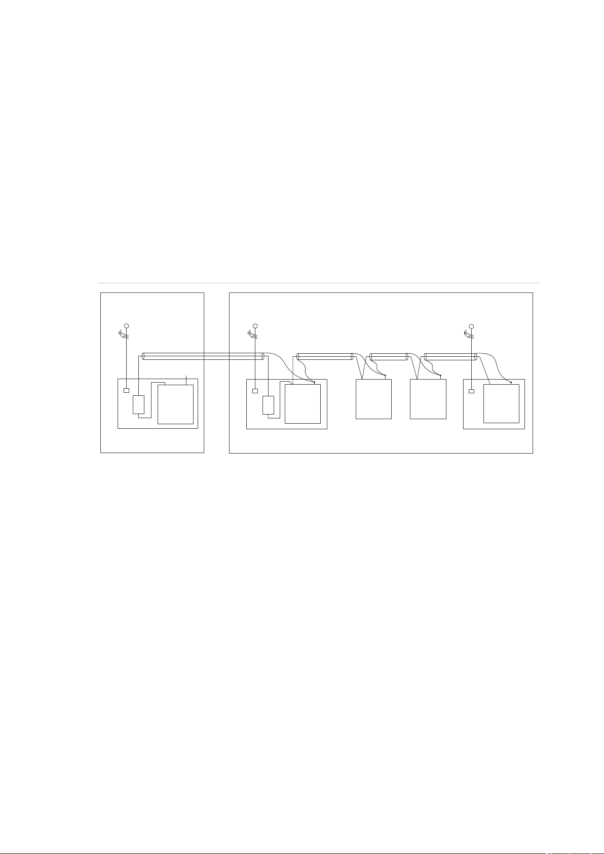
Earthing panels in more buildings
If the wiring extends to separate buildings, more than one common earth system
will be used. Use ATS1740 isolator/repeaters to isolate the system databus. In
this way the system is protected against variations in earth potential.
20 Advisor Advanced ATSx500A(-IP) Installation and Programming Manual
Page 27
Chapter 2: Installation
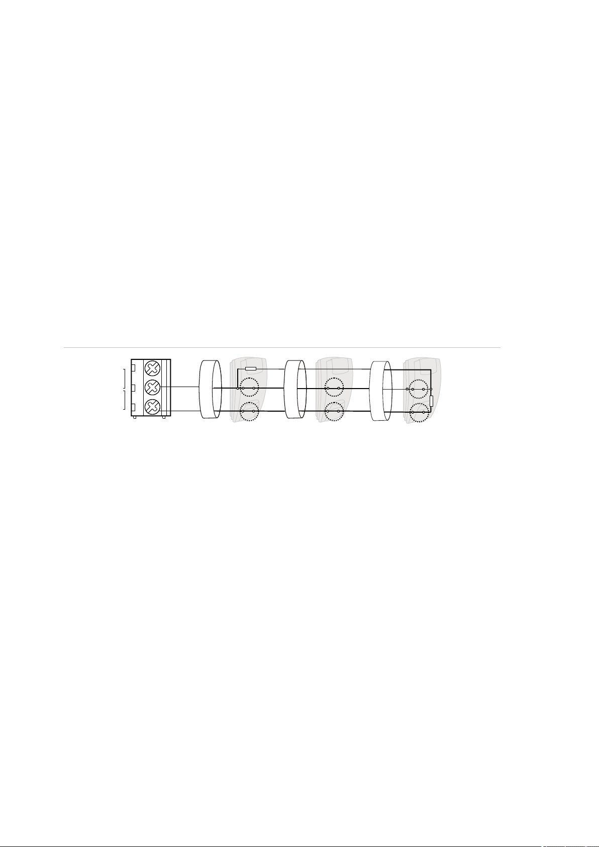
(1) Building 1
(2) Building 2
(3) Mains power with local earth
(4) Earth and shielding
(5) Mains power connector
(6) Advisor Advanced control panel
(7) System databus
(8) Device in plastic housing
(9) Device in metal housing
1740
ATS1201(E)
1740
Advisor
Advanced
ATS1210(E)
ATS1135
ATS1203(E)
(1)
(2)
(3)
(4)
(5)
(6)
(7)
(3)
(3)
(4)
(4)
(4)
(4)
(5)
(5)
(7)
(7)
(8)
(9)
(8)
(9)
(9)
Shielding
The shielding of all shielded cables used in the system should only be connected
at one side to one common earthing point in a building (see Figure 15 below). If a
shielded databus cable is routed via more than one plastic device the shielding
from incoming and outgoing cable must be connected.
In case the IP connection is used, take care that the Ethernet FTP cable remains
within a single building. Do make use of a proper router or switcher to isolate
Ethernet cables between various buildings.
Figure 15: System shielding
Advisor Advanced ATSx500A(-IP) Installation and Programming Manual 21
Page 28
Chapter 2: Installation
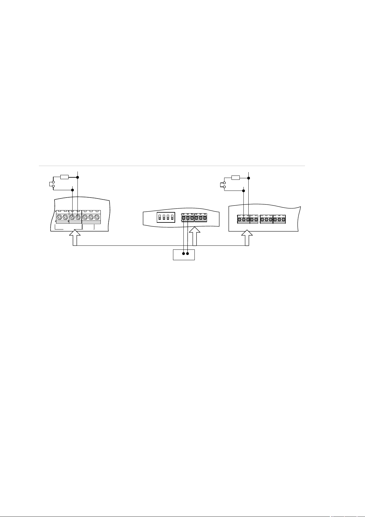
(1) TERM link fitted (first device on local
databus).
(2) Advisor Advanced control panel
variants.
(3) Preferred data cable type is WCAT 52
(two twisted pairs).
(4) Advisor LCD keypad (TERM switch is
set to OFF).
(5) Separate 12 V power supply (required if
keypad is more than 100 m from the
nearest panel or expander. Connect the
negative terminal of the power supply to
the “−” wire of the databus.
(6) TERM link fitted (last device on local
databus).
(7) Any remote expander like ATS1201(E) or
ATS1210(E).
D+0V+12V D- IN OUT
CTD-D+
-
1 C 2 C 3 C
470 ohm
+ -
470 ohm
(1)
(2)
(3)
(5)
(4)
(6)
(7)
EARTH
CTD-
D+
0V
12V
COMMS
TAMPER
Cabling
System databus preferred wiring
The terminator jumper (also called TERM link), or DIP switch must be ON, or a
470 Ω resistor must be fitted at each of the devices at the extreme ends of the
daisy chained databus. In a star-wiring configuration, the TERM link is only fitted
on the devices at the ends of the two longest system databus cable runs.
Figure 16: System databus wiring
System databus connection
The system databus is used to connect remote expanders (to provide extra
zones) and keypads to the Advisor Advanced control panel. Remote devices can
be up to 1.5 km from an Advisor Advanced control panel.
Keypads and remote expanders must be connected via a shielded data cable
with two twisted-pairs from the system databus connection (WCAT 52 is
recommended).
We recommend that you use a separate power supply for a keypad when the
distance between that keypad and the nearest device is more than 100 meters.
If the keypad is powered with a separate power supply, do not connect “+” from
the system databus. Connect “+” of the local power supply to “+” on the keypad,
and connect 0 volts from the power supply and 0 volts from the system databus
22 Advisor Advanced ATSx500A(-IP) Installation and Programming Manual
Page 29

Chapter 2: Installation
C
(1)
T
()2
RA
Z2Z1
A A A
T T
RT
()2 ()2
C
(1)
A
T
()2
RA
Z2Z1
RT
()2 ()2
A
T
A
T
to the keypad terminal marked “−”. The maximum number of devices allowed on
the databus is given in “General features” on page 36.
Two system databuses
Particular panel variants allow you to connect more bus devices by using a
second system databus. To install another system databus, use ATS670 second
RS485 LAN extension module.
System addresses of devices connected to the additional bus (BUS2) are
determined by adding 16 to keypad physical addresses, and 15 to expander
addresses. So, BUS1 handles keypads 1 to 16 and expanders 1 to 15, while
BUS2 — keypads 17 to 32 and expanders 16 to 30.
Note: Door controllers can only be installed on BUS1.
Zone connection
The inputs are set up as standard EOL freely programmable zones. However, by
programming the zones as dual loop, all zone inputs can be programmed to give
a few states indication for the same zone.
Depending on the detector model, do the following to set up zones:
• Choose your EOL connection type. See “EOL connection types” on page 27.
• Program input mode. See “8.6.1 Input mode” on page 248 for the panel, or
“2.2.2.n.4.4 Input mode” on page 152 for expanders.
• Set end-of-line resistor values. See “8.6.2 EOL” on page 248 for the panel, or
“2.2.2.n.4.5 EOL” on page 152 for expanders.
• Configure anti-masking option. See “4.1.n.6.7 Anti mask” on page 175.
Single loop zone wiring
In single loop zone wiring, two zones are required, one zone for alarm and one
zone for tamper. The tamper contacts are wired in series with an EOL resistor.
Figure 17: Single loop examples
Advisor Advanced ATSx500A(-IP) Installation and Programming Manual 23
Page 30
Chapter 2: Installation
(1) Zone terminal
C Common terminal
Z1 Zone 1 input
Z2 Zone 2 input
(2) Detector
A Alarm relay
T Tamper relay
(1) Zone terminal
C Common terminal
Z1 Zone 1 input
Z2 Zone 2 input
(2) Detector
A Alarm relay
T Tamper relay
C
Z2
(1)
RA
A
()2
RT
T
Z1
A A
T T
()2 ()2
Dual loop zone wiring
In dual loop wiring, one zone can detect a few detector states. At least two
resistors are used to define alarm and tamper states. Depending on the
programmed settings, there can be additional states defined as masking alarm or
sensor fault. These states can be the following:
• Short (tamper)
• Active (alarm)
• Normal
• Masking
• Sensor fault
• Open (tamper)
Figure 18: Dual loop example
Possible EOL connections are listed in “EOL connection types” on page 27.
Values for end-of-line resistors
The following list contains the values for end-of-line resistors and possible zone
states. Both the resistance and the voltage measured across the zone are
shown.
Depending on the input type and anti-masking option, the following EOL values
can be available.
24 Advisor Advanced ATSx500A(-IP) Installation and Programming Manual
Page 31

Chapter 2: Installation
Zone state
EOL
Connection
details [1]
Measure [2]
Short
Masking
Normal
Alarm
Fault
Open
Single NC
(Item 1)
No EOL
R (kΩ)
— — <1
>1 — —
U (V)
— — <3.5
>3.5
—
—
Note: Values for other EOL are equal to Dual, except all ranges but normal are
alarm ranges.
Single NO
(Item 2)
No EOL
R (kΩ)
— — >44.70
<44.70
— — U (V)
— — >11.14
<11.14
—
—
Note: Values for other EOL are equal to Dual, except all ranges but normal are
alarm ranges.
Dual
10K
(Item 4)
R (kΩ)
<3.33
3.33–
6.67
6.67–
13.33
13.33–
26.67
—
>26.67
RA=10 kΩ, RT=5 kΩ,
RF=5 kΩ
U (V)
<5.70
5.70–
8.10
8.10–
10.20
10.20–
11.70
—
>11.70
4K7
(Item 3)
R (kΩ)
<1.00
—
1.00–
6.67
6.67–
16.84
—
>16.84
RA=4.7 kΩ, RT=4.7 kΩ
U (V)
<2.41
—
2.41–
8.07
8.07–
10.74
—
>10.74
4K7
(Item 4)
R (kΩ)
<1.00
1.00–
3.42
3.42–
6.67
6.67–
16.84
—
>16.84
RA=4.7 kΩ, RT=2.35 kΩ,
RF=2.35 kΩ
U (V)
<2.41
2.41–
5.79
5.79–
8.07
8.07–
10.74
—
>10.74
4K7
(Item 7)
R (kΩ)
<1.00
16.84–
55.00
1.00–
6.67
6.67–
11.75
11.75–
16.84
>55.00
RA=4.7 kΩ, RT=4.7 kΩ,
RF=10 kΩ
U (V)
<2.41
10.74–
12.70
2.41–
8.07
8.07–
9.82
9.82–
10.74
>12.70
2K2
(Item 4)
R (kΩ)
<0.73
0.73–
1.47
1.47–
2.93
2.93–
5.87
—
>5.87
RA=2.2 kΩ, RT=1.1 kΩ,
RF=1.1 kΩ
U (V)
<1.90
1.90–
3.30
3.30–
5.30
5.30–
7.70
—
>7.70
6K8
(Item 4)
R (kΩ)
<2.27
2.27–
4.53
4.53–
9.07
9.07–
18.13
—
>18.13
RA=6.8 kΩ, RT=3.4 kΩ,
RF=3.4 kΩ
U (V)
<4.50
4.50–
6.80
6.80–
9.10
9.10–
11.00
—
>11.00
5K6
(Item 4)
R (kΩ)
<1.87
1.87–
3.73
3.73–
7.47
7.47–
14.93
—
>14.93
RA=5.6 kΩ, RT=2.8 kΩ,
RF=2.8 kΩ
U (V)
<3.90
3.90–
6.10
6.10–
8.50
8.50–
10.50
—
>10.50
Advisor Advanced ATSx500A(-IP) Installation and Programming Manual 25
Page 32

Chapter 2: Installation
Zone state
EOL
Connection
details [1]
Measure [2]
Short
Masking
Normal
Alarm
Fault
Open
3K74
(Item 4)
R (kΩ)
<1.25
1.25–
2.45
2.45–
4.99
4.99–
9.98
—
>9.98
RA=3.74 kΩ, RT=1.87 kΩ,
RF=1.87 kΩ
U (V)
<2.90
2.90–
4.80
4.80–
7.10
7.10–
9.40
—
>9.40
3K3
(Item 4)
R (kΩ)
<1.10
1.10–
2.20
2.20–
4.40
4.40–
8.80
—
>8.80
RA=3.3 kΩ, RT=1.65 kΩ,
RF=1.65 kΩ
U (V)
<2.60
2.60–
4.40
4.40–
6.70
6.70–
9.00
—
>9.00
2K
(Item 4)
R (kΩ)
<0.67
0.67–
1.33
1.33–
2.67
2.67–
5.33
—
>5.33
RA=2 kΩ, RT=1 kΩ,
RF=1 kΩ
U (V)
<1.70
1.70–
3.00
3.00–
5.00
5.00–
7.30
—
>7.30
1K5
(Item 4)
R (kΩ)
<0.50
0.50–
1.00
1.00–
2.00
2.00–
4.00
—
>4.00
RA=1.5 kΩ, RT=0.75 kΩ,
RF=0.75 kΩ
U (V)
<1.30
1.30–
2.40
2.40–
4.10
4.10–
6.30
—
>6.30
2K2+4K7
(Item 3)
R (kΩ)
<3.60
—
3.60–
5.60
5.60–
8.20
—
>8.20
RA=2.2 kΩ, RT=4.7 kΩ
U (V)
<6.00
—
6.00–
7.50
7.50–
8.80
>8.80
1K
(Item 7)
R (kΩ)
<0.51
4.52–
40.00
0.51–
1.52
1.52–
2.94
2.94–
4.52
>40.00
RA=1 kΩ, RT=1 kΩ,
RF=12 kΩ
U (V)
<1.35
6.24–
12.33
1.35–
3.36
3.36–
5.29
5.29–
6.74
>12.33
8K2
(Item 5)
R (kΩ)
<1.50
—
1.50–
5.84
5.84–
14.25
—
>14.25
RA=8.2 kΩ, RT=8.2 kΩ
U (V)
<3.33
—
3.33–
7.52
7.52–
10.33
—
>10.33
8K2
(Item 6)
R (kΩ)
<1.50
14.25–
45.00
1.50–
5.84
5.84–
10.07
10.07–
14.25
>45.00
RA=8.2 kΩ, RT=8.2 kΩ,
RF=8.2 kΩ
U (V)
<3.33
10.33–
12.48
3.33–
7.52
7.52–
9.37
9.37–
10.33
>12.48
[1] Refer to Figure 19 on page 27.
[2] Zone resistance R (kΩ), zone voltage U (V).
— The state is not available
26 Advisor Advanced ATSx500A(-IP) Installation and Programming Manual
Page 33

Chapter 2: Installation
(1) Single NC
(2) Single NO
(3) Dual A (default)
(4) Dual A with AM
(5) Dual B
(6) Dual C with AM
(7) Dual D with AM
A Alarm relay
T Tamper relay
F Fault / Anti-mask alarm relay
RA Alarm resistor
RT Tamper resistor
RF Fault / Anti-mask alarm resistor
RA
C
Z1
A
C
Z1
RA
A
A
RA
RT
C
Z1
T
A
T
RA
RF
C
Z1
F
RT
ART
RA
C
Z1
T
A
F
RF
RA
RT
C
Z1
T
A
F
RA
RF
RT
C
Z1
T
EOL connection types
The following EOL connections are used for different input types and EOL
values. See “Values for end-of-line resistors” on page 24 for more details.
Figure 19: Connection type
Caution: When using connection types (4), (6) and (7), the antimask option of
the zone must be enabled. Other zones must have this option disabled. See
“4.1.n.6.7 Anti mask” on page 175.
Advisor Advanced ATSx500A(-IP) Installation and Programming Manual 27
Page 34

Chapter 2: Installation
(1) Siren EOL resistor (1 kΩ). It must be
installed if siren does not contain a
built-in resistor.
(2) Siren.
(3) Beacon.
(4) Siren tamper EOL resistor.
(5) Siren tamper (normally closed).
(1) Earthing
(2) External tamper (normally closed)
(3) Optional pry-off tamper (normally
closed) required by EN 50131
Grade 3 and VdS-C regulations
S4
S5
+
+
S1
C
+
S2
C
T C
+
+
- -
LC-OUTPUTS
HC-OUTPUTS
SIR TMP AUX POWER
+
S3
C
(4)
(5)
(1)
(2)
(1)
(2)
(1)
(2)
S4
S5
+
+
S1
C
+
S2
C
T C
+
+
- -
LC-OUTPUTS
HC-OUTPUTS
SIR TMP AUX POWER
+
S3
C
(4)
(5)
(1)
(2)
(3)
(1)
(2)
EARTH
CTD-
D+
0V
12V
COMMS
TAMPER
()1
()2
()3
Siren connection
Figure 20: Siren connection examples
Note: Siren output can be configured as internal or external. This is accomplished via panel
settings, not by configuring the panel hardware. See “Default output assignments” on page 31
and “Outputs” on page 67.
Other connections
Tamper connection
Figure 21: Earthing and tamper connection in ATSx500A(-IP)
PSTN connection
To connect PSTN in ATSx500A(-IP) control panels, use ATS7700 PSTN module.
See ATS7700 PSTN Module Installation Sheet for details.
Caution: If the PSTN line is provided via the ADSL network, make sure that at
least ADSL splitter/filter is used, otherwise the PSTN communication quality may
be too low for a reliable reporting.
28 Advisor Advanced ATSx500A(-IP) Installation and Programming Manual
Page 35

Chapter 2: Installation
(1) Ethernet RJ45
IP
USB
MI
IP
(1)
Ethernet connection
Figure 22: Ethernet connection
The Ethernet port is an IEEE 802.3u based connection supporting 10BASE-T or
100BASE-TX link speeds.
Use only FTP Cat 5e type cable for Ethernet connections.
Advisor Advanced ATSx500A(-IP) Installation and Programming Manual 29
Page 36

Chapter 2: Installation
Configuration
Defaulting the panel
When the panel is initially powered up, you are prompted to choose the
appropriate default settings. Choose the correct settings for your local
regulations. The panel then completes the installation process. See “Initial startup” on page 114.
Note: At least one keypad with an LCD should be connected to the system
databus.
Zone configuration
Internal expansion
The number of zones connected directly to the control panel can be extended
using the ATS608 module. The maximum internal zone capacity for each control
panel is shown in “Specifications > General features” on page 36.
External expansion
Expanders can be used to expand the Advisor Advanced control panels with
external zones. The maximum zone number for each control panel is listed in
“Specifications > General features” on page 36.
A standard expander can have eight zones connected to it. Some of them can be
expanded in increments of 8, up to 32, so an expander can have 8, 16, 24 or
32 zones.
Note: Zone capacity is the number of configurable zones in the system. These
zones may be located at any available input. See “Specifications > General
features” on page 36.
Outputs
There are 5 outputs on the panel PCB. Output expander can be used to add
another 16 outputs inside the panel.
Output controllers are used to expand the number of outputs on an expander. An
expander output controller expands the outputs by 8. An expander can have two
output controllers connected, increasing the outputs to a maximum of 16 per
expander.
A keypad can have only one output in current panel version.
The maximum output number for each control panel is shown in “Specifications >
General features” on page 36.
30 Advisor Advanced ATSx500A(-IP) Installation and Programming Manual
Page 37

Chapter 2: Installation
Output
Name
Type
Default output function
Panel 1
S1
High current output
EN 50131 Grade 3: Internal siren output S1
VdS: External siren output S1
Panel 2
S2
High current output
EN 50131 Grade 3: External siren output S1
VdS: External siren output S2
Panel 3
S3
High current output
EN 50131 Grade 3: Programmable siren output
VdS: External strobe output S3
Panel 4
S4
Low current output
A1 ready to set
Panel 5
S5
Low current output
A1 set
Keypad 7
—
Virtual
Continuous buzzer sound
Keypad 8
—
Virtual
Intermittent buzzer sound
Notes
• Low current output S4 is active when the system is ready to set. Low current
output S5 is active when the system is armed.
• Set keypad output 7 to activate continuous keypad buzzer sound, or output 8
to activate intermittent sound.
Siren outputs
The siren outputs on the Advisor Advanced control panel have addresses
starting from 1 (see Table 2 below).
On expanders with siren speaker outputs, output 16 is the siren output.
To enable the siren output, the programmed output must have the required
condition filter assigned (defined by an alarm event or a siren event, depending
on the preference settings). See “Outputs” on page 67 for more details.
Default output assignments
The default output assignments are shown in Table 2 below.
Table 2: Default output assignments
Note: Output assignments may require adjustment to comply with EN 50131.
Zone, output, and door addressing
Zones and outputs
Table 3 on page 32 shows the zone and output addressing in the Advisor
Advanced system.
Note: This is the default numbering in a classic numbering scheme. To change it
and create objects with numbering independent on physical inputs or outputs,
use menu “8.7.9 Object scheme” on page 253.
Advisor Advanced ATSx500A(-IP) Installation and Programming Manual 31
Page 38

Chapter 2: Installation
Device
Zones
Outputs
Device
Zones
Outputs
Panel
1–8
1–8
2X ATS1810 relay
cards
—
17–24 [1]
Input expander
(ATS608)
9–16
N/A
Output expander
(ATS62x)
—
9–16 [2]
Expander 1
17–48
17–48
Keypad 1
—
1001–1008
Expander 2
49–80
49–80
Keypad 2
—
1009–1016
Expander 3
81–112
81–112
Keypad 3
—
1017–1024
Expander 4
113–144
113–144
Keypad 4
—
1025–1032
Expander 5
145–176
145–176
Keypad 5
—
1033–1040
Expander 6
177–208
177–208
Keypad 6
—
1041–1048
Expander 7
209–240
209–240
Keypad 7
—
1049–1056
Expander 8
241–272
241–272
Keypad 8
—
1057–1064
Expander 9
273–304
273–304
Keypad 9
—
1065–1072
Expander 10
305–336
305–336
Keypad 10
—
1073–1080
Expander 11
337–368
337–368
Keypad 11
—
1081–1088
Expander 12
369–400
369–400
Keypad 12
—
1089–1096
Expander 13
401–432
401–432
Keypad 13
—
1097–1104
Expander 14
433–464
433–464
Keypad 14
—
1105–1112
Expander 15
465–480 [3]
465–496
Keypad 15
—
1113–1120
Expander 16 [4]
497–528
497–528
Keypad 16
—
1121–1128
Expander 17
529–560
529–560
Keypad 17 [4]
—
1129–1136
Expander 18
561–592
561–592
Keypad 18
—
1137–1144
Expander 19
593–624
593–624
Keypad 19
—
1145–1152
Expander 20
625–656
625–656
Keypad 20
—
1153–1160
Expander 21
657–688
657–688
Keypad 21
—
1161–1168
Expander 22
689–720
689–720
Keypad 22
—
1169–1176
Expander 23
721–752
721–752
Keypad 23
—
1177–1184
Expander 24
753–784
753–784
Keypad 24
—
1185–1192
Expander 25
785–816
785–816
Keypad 25
—
1193–1200
Expander 26
817–848
817–848
Keypad 26
—
1201–1208
Expander 27
849–880
849–880
Keypad 27
—
1209–1216
Expander 28
881–912
881–912
Keypad 28
—
1217–1224
Expander 29
913–944
913–944
Keypad 29
—
1225–1232
Expander 30
945–976
945–976
Keypad 30
—
1233–1240
Keypad 31
—
1241–1248
Keypad 32
—
1249–1256
Table 3: Zone and output numbering
[1] Output 17 to 24 states are duplicated on ATS1810 relays and Expander 1 outputs.
32 Advisor Advanced ATSx500A(-IP) Installation and Programming Manual
Page 39

Chapter 2: Installation
Door controller
Doors
Zones
Outputs
1
17–20
17–48
17–48
2
21–24
49–80
49–80
3
25–28
81–112
81–112
4
29–32
113–144
113–144
5
33–36
145–176
145–176
6
37–40
177–208
177–208
7
41–44
209–240
209–240
8
45–48
241–272
241–272
9
49–52
273–304
273–304
10
53–56
305–336
305–336
11
57–60
337–368
337–368
12
61–64
369–400
369–400
[2] When using ATS624 relay card with the ATS1810 expander attached, expander output 8
state is inverted.
[3] Inputs 17 to 32 of Expander 15 cannot be used.
[4] You cannot connect more than 15 expanders and 16 keypads to one system databus. To
connect more bus devices to a panel, it is necessary to install ATS670 second RS485 LAN
extension module. See also “Two system databuses” on page 23.
Doors
There are two types of doors, intelligent and standard. Standard doors (1 to 16)
are handled by the control panel. Keypads or readers 1 to 32 connected to the
Advisor Advanced control panel system databuses are used for simple access
control functions.
Intelligent doors (17 to 64) are controlled by door controllers. Keypads or readers
connected to local databuses of door controllers are named “door controller
readers (DC readers)” and are used for advanced access control functions.
See “Doors” on page 68 for more details.
Table 4 below shows the door, zone and output numbering for door controllers.
Table 4: Door, zone, and output numbering in door controllers
Advisor Advanced ATSx500A(-IP) Installation and Programming Manual 33
Page 40

Chapter 2: Installation
Function
Door
Door controller
1 2 3 4 5 6 7 8 9
10
11
12
Unlock relay
1st door
17
49
81
113
145
177
209
241
273
305
337
369 2nd door
18
50
82
114
146
178
210
242
274
306
338
370 3rd door
19
51
83
115
147
179
211
243
275
307
339
371 4th door
20
52
84
116
148
180
212
244
276
308
340
372
Zone no
1st door
17
49
81
113
145
177
209
241
273
305
337
369 2nd door
19
51
83
115
147
179
211
243
275
307
339
371 3rd door
21
53
85
117
149
181
213
245
277
309
341
373 4th door
23
55
87
119
151
183
215
247
279
311
343
375
DOTL zone no
1st door
17
49
81
113
145
177
209
241
273
305
337
369 2nd door
19
51
83
115
147
179
211
243
275
307
339
371 3rd door
21
53
85
117
149
181
213
245
277
309
341
373 4th door
23
55
87
119
151
183
215
247
279
311
343
375
Request to exit
zone no
1st door
18
50
82
114
146
178
210
242
274
306
338
370
2nd door
20
52
84
116
148
180
212
244
276
308
340
372 3rd door
22
54
86
118
150
182
214
246
278
310
342
374 4th door
24
56
88
120
152
184
216
248
280
312
344
376
Shunt zone no
1st door
17
49
81
113
145
177
209
241
273
305
337
369 2nd door
19
51
83
115
147
179
211
243
275
307
339
371 3rd door
21
53
85
117
149
181
213
245
277
309
341
373
4th door
23
55
87
119
151
183
215
247
279
311
343
375
Reader function
IN reader
IN reader 2
OUT reader
OUT reader 2
1st door
1 5 9
13
2nd door
2 6 10
14
3rd door
3 7 11
15
4th door
4 8 12
16
Table 5 below shows the default zone and output assignment for door
controllers.
Table 5: Default zone and output assignment in door controllers
Table 6 below shows the default assignment of door controller local databus
readers to specific doors.
Table 6: Default reader assignment in door controllers
34 Advisor Advanced ATSx500A(-IP) Installation and Programming Manual
Page 41

Chapter 2: Installation
Mains power specifications
Mains input voltage
230 VAC +10%, −15%, 50 Hz 10%
Current consumption at 230 VAC:
ATS1500A(-IP)
300 mA max.
ATS3500A(-IP), ATS4500A-IP
500 mA max.
Transformer output:
ATS1500A(-IP)-SM/LP
20 VAC, 31 VA
ATSx500A(-IP)-MM/MM+/LM
23 VAC, 58 VA
ATS3500A(-IP)-LP
22 VAC, 53 VA
Power supply specifications
Power supply type
Type A per EN 50131-6
Type I per VdS 2115
Power supply voltage [1]
13.8 V 0.2 V
Power supply current:
ATS1500A(-IP)
1.10 A max. at 13.8 V 0.2 V
ATS3500A(-IP)
2.10 A max. at 13.8 V 0.2 V
ATS4500A-IP
2.65 A max. at 13.8 V 0.2 V
Main board consumption:
ATSx500A
100 mA at 13.8 V ±0.2 V
ATSx500A-IP
150 mA at 13.8 V ±0.2 V
Maximum system current available [2]:
ATS1500A
1000 mA at 13.8 V ±0.2 V
ATS1500A-IP
950 mA at 13.8 V ±0.2 V
ATS3500A
2000 mA at 13.8 V ±0.2 V
ATS3500A-IP
1950 mA at 13.8 V ±0.2 V
ATS4500A-IP
2500 mA at 13.8 V ±0.2 V
Auxiliary power output (AUX. POWER) [3]
13.8 V 0.2 V, 1 A max.
Battery power output (BAT) [4]
13.8 V 0.2 V, 2.5 A max.
Battery type
Lead acid rechargeable: [5]
7.2 Ah, 12 V nom. (BS127N)
12 Ah, 12 V nom. (BS130N)
18 Ah, 12 V nom. (BS131N)
26 Ah, 12 V nom. (BS129N)
36 Ah, 12 V nom. (BS134N)
Specifications
For a list of panel models see “List of panel variants” on page iii.
Advisor Advanced ATSx500A(-IP) Installation and Programming Manual 35
Page 42

Chapter 2: Installation
Maximum voltage at power supply, auxiliary
power output and battery power output
14.5 V
Battery low condition
From 9.5 to 10.5 V
Battery test level [6]
11.2 V
Minimum voltage (battery recharging) at
power supply, auxiliary power output and
battery power output [7][8]
9.45 V
Maximum ripple voltage V, p-p [9]
100 mV typical, 300 mV max.
Overvoltage trigger value [10]
15.5 V min.
[1] The power supply voltage is monitored according EN 50131 Grade 3 and VdS-C regulations.
[2] Current available for auxiliary power and battery charge outputs.
[3] Maximum permanent current to power devices external to the control equipment in the
absence of alarm conditions. The sum of the auxiliary and COMM power output current
cannot exceed the maximum current specified in “Auxiliary current and battery capacity” on
page 39.
[4] Battery output provides battery shortcut protection (according to VdS requirements).
[5] The housings applicable for particular batteries are specified in “Auxiliary current and battery
capacity” on page 39.
[6] If during a manual or a programmed battery test the battery voltage drops below this
threshold, the battery test fails.
[7] Deep discharge protection mechanism monitors the battery voltage and disconnects the
battery if the voltage falls below indicated value, as required by EN 50131 Grade 3 and VdS-
C regulations.
[8] A specific fail message is generated when any output fails.
[9] Max ripple voltage only when empty battery is charging.
[10] Overvoltage protection mechanism monitors the power supply voltage and shuts down the
PSU if the voltage raises above indicated value, as required by EN 50131 Grade 3 and VdS-
C regulations.
General features
ATS1500A(-IP)
ATS3500A(-IP)
ATS4500A-IP
Code combinations
From 10,000 (4 digits) to 10 billion (10 digits)
End-of-line resistor
1 kΩ, 1.5 kΩ, 2 kΩ, 2.2 kΩ, 3.3 kΩ, 3.74 kΩ,
4.7 kΩ (default), 5.6 kΩ, 6.8 kΩ, 8.2 kΩ, 10 kΩ
Onboard zones
8 (expandable to 16 with 1X ATS608)
Maximum zone number
32
128
512
Onboard outputs
5 (expandable to 9 with 1X ATS624, or to 21 with
1X ATS626).
See “Standard onboard outputs” on page 37.
Maximum output number
128
Areas 4 8
64
Area groups
— — 64
Maximum keypad / RAS number
8
16
32 [1]
Maximum expander / DGP number
7
15
30 [1]
[1] It is necessary to install ATS670 second RS485 LAN extension module to connect more
than 16 RASes and 15 DGPs.
36 Advisor Advanced ATSx500A(-IP) Installation and Programming Manual
Page 43

Chapter 2: Installation
Maximum user number (for users with
SMS and voice reporting functionality)
50
200
1000
User groups
16
64
128
Inhibit / isolate / shunt limit, max.
32
128
512
Schedules
24
Time frames
4 per schedule
Special days
8
Actions per schedule
20
Event log capacity
Note: See also “Events” on page 79.
15500, which includes:
- 1000 mandatory events
- 1500 non-mandatory events
- 10000 access events
- 1000 installer events
- 1000 dialler events
- 1000 extended events
Data retention (log, program settings)
20 years
Access control features
ATS1500A(-IP)
ATS3500A(-IP)
ATS4500A-IP
Door controllers supported
7
12
12
Standard doors
4 8 16
Intelligent doors
28
48
48
Regions
256
Door groups
128
Maximum user number (with door
controllers connected)
2000
17488 (with ATS1831 IUM installed)
64532 (with ATS1832 IUM installed)
Note: SMS and voice reporting features are only available for a limited user number. Maximum
number of users with full control and reporting functionality is given in “General features” on
page 36.
Ethernet connection (IP only)
Supported standard
IEEE 802.3u
Speed
10BASE-T or 100BASE-TX
Duplex
Half-duplex and full-duplex
Cabling
FTP (foiled twisted pair) Cat 5e cable or better
Autonegotiation
MDIX
Standard onboard outputs
S1, S2, S3
High current electronic output, rating: 1 A at 13.8 V
S4, S5 [1]
Low current electronic output, rating: 50 mA at 13.8 V
[1] Maximum cable length for low current output connection may not exceed 30 m. For longer
distances, use relay output expansion (for example, ATS624 four-relay expander).
Advisor Advanced ATSx500A(-IP) Installation and Programming Manual 37
Page 44

Chapter 2: Installation
Environmental
Operating temperature
0 to +40°C
Tested temperature according
EN 50131
−10 to +55°C
Humidity
95% noncondensing
IP protection grade
IP31
Colour
Beige
Dimensions
See “List of panel variants” on page iii
EN 50131 grade and class
ATS1500A(-IP): Grade 2, Class II
ATS3500A(-IP): Grade 3, Class II
ATS4500A-IP: Grade 3, Class II
Note: ATS1500A(-IP)-MM can be upgraded to an EN
Grade 3 setup with the use of the ATS-MM-TK tamper
kit. ATS1500A(-IP)-SM can be upgraded to an EN
Grade 3 setup with the use of the ATS-SM-TK tamper
kit.
Safety class
Class I
Enclosure type
Enclosure (meets UL94V-0)
Overvoltage category
Category II
Maximum altitude, or minimum air
pressure
2000 m above mean sea level
Fuses
Battery
ATS1500A(-IP), ATS3500A(-IP): 2 A, resettable
ATS4500A(-IP): 3 A, resettable
12 V aux
1 A, resettable
System databus
1 A, resettable
Siren 1, high current output S1
1 A, resettable
Siren 2, high current output S2
1 A, resettable
Siren 3, high current output S3
1 A, resettable
Mains, mains fuse:
ATS1500A(-IP)
315 mA, fast 20x5
ATS3500A(-IP), ATS4500A-IP
630 mA, fast 20x5
Note: Mains fuse is part of the mains terminal block.
WARNING: Before removing the mains fuse, mains power must be disconnected
(see “Mains power connection” on page 16).
38 Advisor Advanced ATSx500A(-IP) Installation and Programming Manual
Page 45

Chapter 2: Installation
Battery capacity, Ah
7.2
12
18
Applicable housing
SM, MM, LP
LP
MM
Security approval / Grade
Discharge
time, h
Charge
time, h
Auxiliary current, mA
EN Grade 2
12
72
450
750
750
INCERT
24
24
150
350
400
EN Grade 3, VdS-B
30
24
90
250
350
NF&A2P Grade 2 (EN+RTC)
36
72 — 180
350
NF&A2P Grade 3 (EN+RTC), VdS-C
60
24 — —
150
Battery capacity, Ah
7.2
12
18
Applicable housing
MM, LP
LP
MM
Security approval / Grade
Discharge
time, h
Charge
time, h
Auxiliary current, mA
EN Grade 2
12
72
450
850
1350
INCERT
24
24
150
350
600
EN Grade 3, VdS-B
30
24
90
250
450
NF&A2P Grade 2 (EN+RTC)
36
72 — 180
350
NF&A2P Grade 3 (EN+RTC), VdS-C
60
24 — —
150
Battery capacity, Ah
7.2
12
18
25
36
Applicable housing
MM+, LM
LM
MM+, LM
LM
LM
Security approval /
Grade
Discharge
time, h
Charge
time, h
Auxiliary current, mA
EN Grade 2
12
72
450
850
1350
1600
1600
INCERT
24
24
150
350
600
875
900
EN Grade 3, VdS-B
30
24
90
250
450
675
700
NF&A2P Grade 2
(EN+RTC)
36
72 — 180
350
540
850
NF&A2P Grade 3
(EN+RTC), VdS-C
60
24 — —
150
260
450
Auxiliary current and battery capacity
Table 7: ATS1500A(-IP) maximum available auxiliary current
Table 8: ATS3500A(-IP) maximal available auxiliary current
Table 9: ATS4500A-IP maximal available auxiliary current
Note: 18 Ah battery blocks some entry holes in the MM housing.
Example for ATS1500A(-IP) EN Grade 2
When using battery backup as specified for EN Grade 2 using a 12 Ah battery,
the maximum available auxiliary current is 750 mA.
Advisor Advanced ATSx500A(-IP) Installation and Programming Manual 39
Page 46

Chapter 2: Installation
Monitoring function
Message
Cause
AC Mains
Mains fail
Loss of external power supply [1]
Battery
Battery low
Battery low voltage [1]
Battery test fail
Exhausted battery
Battery charger fail
Fuse/power output fail
Output overload
Power outputs
Fuse/power output fail
Exhausted fuse
Fuse loss
Short circuit
Overload
Power supply
Power unit/power output fail
Power unit failure
Overvoltage
Tampers
Device tamper
Device sabotage
Example for ATS3500A(-IP) EN Grade 3
When using battery backup as specified for EN Grade 3 using an 18 Ah battery,
the maximum available auxiliary current is 450 mA.
This current is the max grand total available current that may be used for
auxiliary components such as:
• Devices on the Advisor Advanced system databus
• Detectors on the auxiliary power output
• Communication devices via MI-bus (e.g. GSM, IP)
Temporary used current such as: Sirens and Strobes are not included.
Fuse rating must be taken into account.
Battery status information
Various detection ways are provided to understand the status of a battery.
A short battery test will be applied to detect following within 10 seconds:
• Battery fail (or battery missing) to inform installer no battery is attached or a
poor battery is attached. Event will be logged and notified.
• Low battery as soon as battery becomes below 10.5 V with or without mains.
Event will be logged, notified and reported.
Another battery test will be applied once per day to even better understand
battery status. In case battery wears out a battery fail message will be logged,
notified and reported.
System monitoring
The system provides monitoring for the following items.
Table 10: Monitored items
[1] Mains fail and Battery low will finally result in Battery deep discharge protection.
40 Advisor Advanced ATSx500A(-IP) Installation and Programming Manual
Page 47

Chapter 3
System functions
Summary
This section lists and describes all functionality functions provided by Advisor
Advanced control panels.
Note: Particular functionality may be unavailable depending on panel variant,
firmware version or hardware configuration.
Content
Function list 43
Zones 45
Zone types 45
Areas 50
Set and unset 51
Delayed unset 52
Inhibit and isolate 53
Inhibit 53
Isolate 53
Zone shunt 53
Door shunt 69
Keys 54
Common key sequences for LCD keypad 54
Common key sequences for keypad without LCD 55
Function keys 57
Bus devices 58
Bus device numbering 58
Adding keypad with a higher number 58
Keypads 58
Expanders 59
Users 60
Predefined users 60
User data lock 61
User groups 62
PIN 66
Outputs 67
Advisor Advanced ATSx500A(-IP) Installation and Programming Manual 41
Page 48

Chapter 3: System functions
Condition filters 74
Triggers 76
Calendar 77
Events 79
Log 79
Programming 79
Tests and diagnostics 80
Walk test 80
Other tests 83
Alarm reporting 84
Reporting principles 84
Reporting order 85
Failed to communicate (FTC) 86
User programmable functions 88
Autoset 91
Wireless device programming 92
Learning wireless sensors 92
Learning fobs 94
Two-zone RF sensors 96
Device activation 97
Using cameras 98
Configuration 98
Diagnostics 100
Troubleshooting 100
Engineer reset 102
Timed unset / ATM 103
42 Advisor Advanced ATSx500A(-IP) Installation and Programming Manual
Page 49

Chapter 3: System functions
Function
Reference
Access control
“Access control” on page 68
Areas
“Areas” on page 50
ATM
“Timed unset / ATM” on page 103
Autoset
“Autoset” on page 91
Calendar
“Calendar” on page 77
Cameras
“Using cameras” on page 98
Condition filters
“Condition filters” on page 74
Diagnostics
“Tests and diagnostics” on page 80
Doors
“Doors” on page 68
Events
“Events” on page 79
Expanders / DGPs
“Bus devices” on page 58, “Expanders” on page 59
Inhibit
“Inhibit and isolate” on page 53
Inputs
“Zones” on page 45
Isolate
“Inhibit and isolate” on page 53
Keypads / RASes
“Bus devices” on page 58, “Keypads” on page 58
Keys
„Keys” on page 54
Outputs
“Outputs” on page 67
Part set
“Set and unset” on page 51
PIN
“PIN” on page 66
Reporting
“Alarm reporting” on page 84
Set
“Set and unset” on page 51
Shunt
“Zone shunt” on page 53, “Door shunt” on page 69
Tests
“Tests and diagnostics” on page 80
Timed unset
“Timed unset / ATM” on page 103
Triggers
“Triggers” on page 76
Unset
“Set and unset” on page 51
User groups
“User groups” on page 62
User programmable functions
“User programmable functions” on page 88
Users
“Users” on page 60
Walk test
“Walk test” on page 80
Function list
Table 11 below provides an alphabetic list of Advisor Advanced functions and
their description references.
Table 11: Function list
Advisor Advanced ATSx500A(-IP) Installation and Programming Manual 43
Page 50

Chapter 3: System functions
Function
Reference
Wireless devices
“Wireless device programming” on page 92
Zones
“Zones” on page 45
44 Advisor Advanced ATSx500A(-IP) Installation and Programming Manual
Page 51

Chapter 3: System functions
Zones
Zone is an electrical signal from a security device or a group of devices (PIR
detector, door contact) to the Advisor Advanced system. Each device can be
identified by a zone number or a name. For example, zone 14, Fire Exit Door.
Zone connection is described in Chapter 2 “Installation” > “Zone connection” on
page 23.
For zone configuration, see “Zone configuration” on page 30.
Zone addressing is described in “Zone, output, and door addressing” on page 31.
Zone programming is done via “4.1 Zone menu” on page 171 (in Chapter 5
“Menu reference”).
Zone types
The following zone types are available.
1. Alarm
Generates no alarm when the area is unset.
Generates an alarm when the area is set.
Example: Internal door, PIR (motion detector).
2. Entry/Exit 1
Generates no alarm when the area is unset.
When the area is set, the exit timer starts and activating the zone generates no
alarm. If the zone is activated when the exit time has expired, the entry timer
starts. Only when the entry time has expired, an alarm is generated.
Example: Front door.
You need to program the entry/exit time. See “4.2 Areas” on page 185 for more
information.
3. Access
Generates no alarm when the area is unset.
Generates an alarm when the area is set, and the no exit timer or entry timer is
not running.
Example: PIR at entrance with a door contact on the entry door.
You need to program the entry/exit time. See “4.2 Areas” on page 185 for more
information.
Advisor Advanced ATSx500A(-IP) Installation and Programming Manual 45
Page 52

Chapter 3: System functions
4. Fire
Generates a fire alarm regardless of the status of the area.
Fire alarm causes pulsing siren sound. This alarm has higher priority than an
intrusion alarm.
Example: Smoke detector.
5. Panic
Generates a panic alarm regardless of the status of the area.
Example: panic button.
See also “8.8.1 Panic mode” on page 254.
6. 24H
Generates an intrusion alarm regardless of the status of the area.
7. Tamper
Generates a tamper alarm regardless of the status of the area.
Example: Panel tampers.
8. Exit terminator
This zone type is used to terminate an exit time. If the zone switches from active
to normal, the exit time is terminated and the area(s) are completely set as soon
as the final set delay has expired (see also “8.1.3.5 Final set delay” on page
235”).
9. Keyswitch
When the zone switches, the area is set / unset / part set depending on the zone
options selected.
Example: Key switch next to Front door.
See options “4.1.n.6.16 Key latch” on page 176, “4.1.n.6.17 Key set” on page
176, “4.1.n.6.18 Key unset” on page 177.
10. Medical
Generates a medical alarm regardless of the status of the area.
11. Technical
Generates a technical alarm regardless of the status of the area.
Example: temperature sensor.
See options “4.1.n.6.19 Technical full set” on page 177, “4.1.n.6.20 Technical
unset” on page 177.
12. Transmission path fault
Monitors the external reporting device.
46 Advisor Advanced ATSx500A(-IP) Installation and Programming Manual
Page 53

Chapter 3: System functions
13. Fire door
If there is no fire alarm present, generate an intrusion alarm regardless of the
status of the area. Otherwise no intrusion alarm is generated.
Example: Fire doors or emergency doors.
See also “4. Fire” on page 46.
14. Aux mains fault
Monitors the auxiliary mains supply.
15. Aux batt fault
Monitors battery of the auxiliary power supply.
16. Key box
Monitors a box that holds a key to premises. It allows you to open for a short
period after setting an area (specified in key box timer, see “8.1.4.5 Key box
time” on page 236). It generates an alarm when opened outside of this period.
17. Eng. reset
This zone activation causes the engineer reset.
18. Entry/Exit 2
An alternative entry/exit zone.
Example: Back entrance.
Entry/exit 2 zone initiates alternative entry/exit timers. See “4.2.n.2 Exit time” on
page 186” and “4.2.n.3 Entry time” on page 186.
See also “2. Entry/Exit 1” on page 45 for more details.
19. Shunt
Zone activation causes shunt of all area zones that have shunting allowed. Shunt
is allowed by the option “4.1.n.6.36 Shunt” on page 181.
See also “Zone shunt” on page 53.
Advisor Advanced ATSx500A(-IP) Installation and Programming Manual 47
Page 54

Chapter 3: System functions
Options:
Zone type
1. Alarm
2. Entry/Exit 1
3. Access
4. Fire
5. Panic
6. 24H
7. Tamper
8. Exit terminator
9. Keyswitch
10. Medical
11. Technical
12. Transmission path fault
13. Fire door
14. Aux mains fault
15. Aux batt fault
16. Key box
17. Eng. reset
18. Entry/Exit 2
19. Shunt
4.1.n.6.1 Inhibit
+ + + + + + + + + + + + + + + + + +
4.1.n.6.2 Isolate
− − − − − − − − − − − − − − − − − −
4.1.n.6.3 Excl. in PS1
− − − − − − − −
4.1.n.6.4 Excl. in PS2
− − − − − − − −
4.1.n.6.5 Double knock
− − − − − − − −
4.1.n.6.6 Swinger shunt
+ + + − − − − − − − +
4.1.n.6.7 Anti mask
− − − − − − −
4.1.n.6.8 Zone pairing
− − − −
4.1.n.6.9 Chime
− − − − − −
4.1.n.6.10 Soak test
− − − − − − − − − − − − −
4.1.n.6.11 Engineer walk
test
+ + + + + + + + + + + + + +
4.1.n.6.12 User walk test
+ + + + + + + + + + +
4.1.n.6.13 Shock sensor
− − − − − −
4.1.n.6.14 Extend EE
− −
4.1.n.6.15 Final door
− − −
4.1.n.6.16 Key latch
−
4.1.n.6.17 Key set — full
set
−
4.1.n.6.17 Key set — part
set
−
4.1.n.6.18 Key unset
−
4.1.n.6.19 Technical full
set
+
4.1.n.6.20 Technical
unset
+
4.1.n.6.21 Technical part
set
+
4.1.n.6.22 Keypad LCD
− − − − − − −
4.1.n.6.23 Log
• • • • • • • + + + • • + + + •
4.1.n.6.24 CS report
• • • • • • • + + + • • + + + •
4.1.n.6.25 Delay timer
− − − −
Table 12: Available zone options
48 Advisor Advanced ATSx500A(-IP) Installation and Programming Manual
Page 55

Chapter 3: System functions
Options:
Zone type
1. Alarm
2. Entry/Exit 1
3. Access
4. Fire
5. Panic
6. 24H
7. Tamper
8. Exit terminator
9. Keyswitch
10. Medical
11. Technical
12. Transmission path fault
13. Fire door
14. Aux mains fault
15. Aux batt fault
16. Key box
17. Eng. reset
18. Entry/Exit 2
19. Shunt
4.1.n.6.26 ACK on
keypad
4.1.n.6.27 ACK by user
4.1.n.6.28 Sensor type
4.1.n.6.29 Virtual zone
4.1.n.6.30 Held open
4.1.n.6.31 EE set check
4.1.n.6.32 Alarm in PS1
4.1.n.6.33 Alarm in PS2
4.1.n.6.34 Report as
4.1.n.6.35 Auto test
4.1.n.6.36 Shunt
− − − −
4.1.n.6.37 View isolated
+
4.1.n.6.38 Stop report
− − − − − − − − − − − − − − − − − − −
Legend:
+ (yes): The option is programmable, the default value is Yes.
− (no): The option is programmable, the default value is No.
• (always): The option is not programmable, the value is always Yes.
Advisor Advanced ATSx500A(-IP) Installation and Programming Manual 49
Page 56

Chapter 3: System functions
Areas
Area is a section of premises that has specific security requirements. The
Advisor Advanced system allows any premises to be divided into different areas
having different security requirements. Each area has zones assigned to it. Each
area is identified by a number or an identifier. For example: Area 1, Main Office,
etc.
Each area can have one of the following statuses:
• Set (armed)
• Part set
• Unset (disarmed)
See “Set and unset” on page 51 for details.
Areas are configured in “4.2 Areas” on page 185 in Chapter 5 “Menu reference”.
Area groups
Particular panel models allow to group areas in area groups. Users are allowed
to perform area operations with area groups in the same way as with areas: for
example, set an area group.
Area groups are configured in “4.3 Area groups” on page 190.
Note: Area group availability depends on the control panel variant. See
“Specifications” on page 35 in Chapter 2 “Installation”.
Area hierarchy
The area hierarchy defines the order, in which high security areas should be set
or unset. A lower value means a higher hierarchy. Areas with higher hierarchy
should be set in the first turn, and unset as the last ones.
This functionality is available only in areas with area hierarchy higher than 0.
An example is a bank vault. It should be impossible to unset the vault
(hierarchy 1) before the vault hall (hierarchy 2) is unset. Also, you cannot set the
vault hall before the vault is set.
Area hierarchy is set via menu “4.2.n.6 Hierarchy” on page 189.
50 Advisor Advanced ATSx500A(-IP) Installation and Programming Manual
Page 57

Chapter 3: System functions
Set and unset
Each area can have one of the following statuses:
• Set (armed): The condition of an area where a change in the status of any
zone (from normal to active) causes an alarm. An area or premise is only set
when it is unoccupied. Some zones (like vaults) can remain armed
continually.
• Unset (disarmed): The condition of an area when it is occupied and normal
activity does not set off an alarm.
• Part set: The condition of part of an area where a change in the status of
certain zones (from normal to active) causes an alarm. An area or premise is
part set when it is partially unoccupied like the outside of a home is part set
but the inside is still unset.
See also “Areas” on page 50.
Areas can be set or unset in one of the following ways:
• By users via a keypad or a reader. See “Users” on page 60 and “Bus devices”
on page 58. The available key sequences are listed in “Keys” on page 54.
• By users via SMS command. See Advisor Advanced SMS Control Reference
Manual for details.
• By operators remotely via management software. See Chapter 6 “Software”
on page 287.
• Automatically via the autoset functionality. See “Autoset” on page 91 for
details.
How to use part set
When users performs a part set, the system sets all requested areas with all full
set (perimeter) zones supervised but all part set (interior) zones ignored. As this
setting mode is for personal safety, reporting to the central station depends on
option “8.4.3.1 Report BA” (see page 244). Further, any alarms that occur while
part set is applied, are treated as local alarms that activate sirens, keypad
buzzers (if enabled), and keypad indicators.
If a zone is assigned multiple areas it is not set until all assigned areas are set. If
there is a mixture of part set and full set areas assigned to the zone, the zone
obeys the part set condition.
Advisor Advanced ATSx500A(-IP) Installation and Programming Manual 51
Page 58

Chapter 3: System functions
Unset delay
Please wait
Delayed unset
The area unset can be delayed. A delayed unset is used in banking applications,
like ATM cash refill and vault opening.
During the delay the area keypad or reader is locked. The following message is
displayed on the keypad LCD screen:
On a keypad or a reader without LCD the unset delay is indicated by slowly
blinking area LED.
The delay period is set in “4.2.n.4.3 Unset delay” on page 188.
There is no way to manually override the delay.
52 Advisor Advanced ATSx500A(-IP) Installation and Programming Manual
Page 59

Chapter 3: System functions
Inhibit and isolate
A faulty device can be inhibited or isolated.
Inhibit
A zone is inhibited from indicating normal or active status. It becomes excluded
from functioning as part of the system for particular time. However, tampers are
still monitored.
The zone is inhibited until the next unset.
A zone can be inhibited automatically when using the forced set functionality. It is
configured via menu “8.4.4 Forced set” on page 244 in Chapter 5 “Menu
reference”.
Isolate
A zone or a bus device is inhibited from indicating normal or active status. It is
excluded from functioning as part of the system permanently, until de-isolating by
the manager or installer.
Zone shunt
A shunt procedure inhibits zones, when active, from generating an alarm during a
certain time period.
A zone can be shunted in the following ways:
• Manually by the installer. Use menu “1.2.1.9 Shunt zones” on page 124.
• By a schedule. See “Calendar” on page 77 for details.
• By a conditional filter. See “Condition filters” on page 74 for details.
• By a zone with Shunt type. See “Zone types” on page 45 for details.
Caution: There is a limitation of the number of zones that can be shunted
simultaneously. The limit is set in “4.2.n.7.3 Shunt limit” on page 190.
During the shunt time the zone is inhibited.
If the zone is still active after the shunt time has expired, the zone will generate
an alarm, depending on the zone type and the status of the area.
For particular users (depending on their user options) the shunt is active during
an extended shunt time.
Before the shunt timer expires, a warning may be given.
Advisor Advanced ATSx500A(-IP) Installation and Programming Manual 53
Page 60

Chapter 3: System functions
Action
Programmed method
Key sequence
[1]
Set [2]
Set with key
On
Set with PIN
On, PIN, Enter
PIN, On
Set with card
Card
On, card
3 x card
Set with card and PIN
On, card, PIN, Enter
Card, PIN, On
Unset [2][3]
Unset with PIN
Off, PIN, Enter
PIN
PIN, Off
Unset with card
Card
Off, card
Unset with card and PIN
Off, card, PIN, Enter
Card, PIN, Off
Card, PIN
Part set [2]
Part set with key
Partset
Part set with PIN
Partset, PIN, Enter
PIN, Partset
Part set with card
Card
Partset, card
3 x card
Part set with card and PIN
Partset, card, PIN, Enter
Card, PIN, Partset
Door access
[2][3]
Door access with PIN
PIN, Enter
Door access with card
Card
Keys
The authorization method depends on system settings. See “2.2.1.n.3.7 Control
options” on page 145 for more information.
Note: When an incorrect PIN is entered three times the keypad is locked for
120 seconds.
Common key sequences for LCD keypad
Table 13: Common key sequences for LCD keypad
54 Advisor Advanced ATSx500A(-IP) Installation and Programming Manual
Page 61

Chapter 3: System functions
Action
Programmed method
Key sequence
[1] Door access with card and PIN
Card, PIN, Enter
Menu access [2]
Menu access with PIN
Menu, PIN, Enter
PIN, Menu
Menu access with card
Menu, card
Menu access with card and PIN
Menu, card, PIN, Enter
Card, PIN, Menu
Duress [4]
Duress with PIN
Any set key (On / Off / Partset),
duress code, Enter
Duress code, any set key
Duress with card and PIN
Any set key (On / Off / Partset),
duress code, card, Enter
Card, duress code, any set key
Change keypad
buzzer volume
Increase volume
X + Right
Decrease volume
X + Left
Panic [5]
Panic alarm
1 + 3
Exit [6]
Quick exit from the programming
Menu + Clear
Active alarms [7]
Display active zones and faults
that should be acknowledged
Function, Function
Alarm memory
[7]
Display alarms that occurred
when set
Enter, Enter
Action
Programmed method
Key sequence
[1]
Set [2]
Set with PIN
On, PIN, On
Set with card
Card
On, card
3 x card
Set with card and PIN
On, card, PIN, On
Card, PIN, On
[1] Use the check box to note which options are available for this system.
[2] The functionality depends on “2.2.1.n.3.7.1 Card&PIN mode” on page 145.
[3] The functionality depends on “8.7.7 Easy unset” on page 253.
[4] The functionality depends on “8.7.3 Duress method” on page 250.
[5] Panic alarm functionality depends on the “8.8.1 Panic mode” option described on page 254. It
also depends on the “2.2.1.n.3.20 1+3 keys” option described on page 149.
[6] The function works only if there is no prompt that requires a user response or action. It is
disabled, for example, during wireless devices learning.
[7] The functionality depends on “8.3.3 Alarm list” on page 241.
Common key sequences for keypad without LCD
Table 14: Common key sequences for keypad without LCD
Advisor Advanced ATSx500A(-IP) Installation and Programming Manual 55
Page 62

Chapter 3: System functions
Action
Programmed method
Key sequence
[1]
Unset [2][3]
Unset with PIN
Off, PIN, On
PIN
PIN, Off
Unset with card
Card
Off, card
Unset with card and PIN
Off, card, PIN, On
Card, PIN, Off
Card, PIN
Part set
Part set with card
Card
3 x card
Door access [2]
Door access with PIN
Any digit, PIN, On
Door access with card
Card
Any digit, card
Door access with card and PIN
Any digit, card, PIN, On
Card, PIN, On
Duress [4]
Duress with PIN
Any set key (On / Off), duress code,
Enter
Duress code, any set key
Duress with card and PIN
Any set key (On / Off), duress code,
card, Enter
Card, duress code, any set key
Panic [5]
Panic alarm
1 + 3
[1] Use the check box to note which options are available for this system.
[2] The functionality depends on “2.2.1.n.3.7.1 Card&PIN mode” on page 145.
[3] The functionality depends on “8.7.7 Easy unset” on page 253.
[4] The functionality depends on “8.7.3 Duress method” on page 250.
[5] Panic alarm functionality depends on the “8.8.1 Panic mode” option described on page 254.
When a PIN can be entered, the keypad beeps twice and flashes the red and
green LEDs. When an operation fails the keypad beeps seven times.
56 Advisor Advanced ATSx500A(-IP) Installation and Programming Manual
Page 63

Chapter 3: System functions
Action
Key
[1] A
B
C
F1 (F + 1)
F2 (F + 2)
F3 (F + 3)
F4 (F + 4)
Function keys
Use Table 15 below to describe function keys functionality and availability.
See also “2.2.1.n.3.12 Function keys” on page 148.
Table 15: Function keys
[1] Use the check box to note which functions are available in this system.
Advisor Advanced ATSx500A(-IP) Installation and Programming Manual 57
Page 64

Chapter 3: System functions
Bus devices
There are the following kinds of bus devices:
• Keypads are used to provide system control, such as setting or unsetting
areas. Depending on the type of keypad, additional functions may be
available, such as LCD displays, menus to set time and date etc.
• Expanders are used to provide remote inputs and outputs.
• Readers are connected to door controllers and used to control intelligent
doors. See “Access control” on page 68 for details.
Bus device numbering
Devices use DIP switches to set bus address. The Advisor Advanced normally
uses the keypad/expander number. For the dependence between device address
and its number, refer to the appropriate bus device installation manual. The
address of the programmed device can be viewed in “2.2.1.n.2 Keypad address”
(keypad) and “2.2.2.n.2 Expander address” (expander).
See also Chapter 2 “Installation > Zone, output, and door addressing” on page
31.
Adding keypad with a higher number
If the number programmed in a keypad is higher than the maximum number
allowed in the system, the keypad cannot be added. But it is possible to change
this number from the panel via the keypad internal menu. Adding a higher
keypad number brings you to a simplified menu that contains only own keypad
menu entry.
For example, to program keypad with programmed number 16 in a system with
8 keypads:
1. Add keypad 16. It will bring you to “2.2.1.n.4 Keypad menu” (described on
page 150).
2. Enter keypad menu.
3. Change keypad address to 7. Refer to the appropriate keypad manual.
4. Add keypad 7.
Keypads
A device that is the user control panel for security options for areas or for access
points (doors). The keypad can be a console (LCD keypad used to program the
58 Advisor Advanced ATSx500A(-IP) Installation and Programming Manual
Page 65

Chapter 3: System functions
control panel, perform user options, view alarms, etc.) or any other device that
can be used to perform security function, such as set/unset, open doors, etc.
Keypads and readers can be also referred as remote arming stations (RASes).
Keypads are configured in “2.2.1 Keypad devices” on page 143 in Chapter 5
“Menu reference”.
Expanders
Expanders are devices that expand number of inputs or outputs in the Advisor
Advanced system. There are two kinds of expanders:
• Internal expanders: Expansion boards that are installed inside the control
panel housing.
• External expanders: Bus devices that collect data from other security devices
within an area, and transfer it to the Advisor Advanced control panel. They
are also referred as expanders or data gathering panels (DGP).
Expander installation and wiring is described in Chapter 2 “Installation” on page
7.
Expander options are set in “2.2.2 Expander devices” on page 150 in Chapter 5
“Menu reference”.
Advisor Advanced ATSx500A(-IP) Installation and Programming Manual 59
Page 66

Chapter 3: System functions
Users
Users are identified to the Advisor Advanced system by a unique number that is
associated with the user’s PIN or card.
Note: If the system is EN 50131 compliant, you can edit only your own settings,
and configure only newly added users. See “User data lock” on page 61 for more
details.
For each user, the system records the following:
• Number
• Name
• PIN
• Card ID number
• Phone number
• User group (which determines options the user can access)
• Door group (which determines regions the user can access)
• Language
• Various programmed options
Note: Your own user group might not allow you to program PINs. If it does allow
use of this option, there might still be restrictions on which user groups you are
allowed to update.
Maximum user number in the system is defined in “Specifications” on page 35.
Note: Connecting door controllers to the Advisor Advanced system increases the
maximum user number in the system (see “Specifications > Access control
features” on page 37 for details). However, additional users do not have the
following records:
• Phone number
• Language
Predefined users
There are two predefined users in the system:
• Installer is used to enter the Advisor Advanced system configuration. He has
user group “Installer group” assigned.
• A user with default name Supervisor who can grant access to the installer
menu for the service engineer. He has user group “Supervisor group”
assigned. The default supervisor PIN is 1122.
Note: If the configured PIN length is configured for more than 4 digits, zeroes are
added to the default PIN values. For example, if the system is configured for 6digit PINs, the supervisor PIN is 112200.
60 Advisor Advanced ATSx500A(-IP) Installation and Programming Manual
Page 67

Chapter 3: System functions
Lock user data?
>Cancel<
There is always one installer in the system. More than one user can have rights
that allow granting access to the installer or service engineer.
See also “User groups” on page 62.
User data lock
When a system is configured as EN 50131 compliant, you are not allowed to
modify settings for an existing user (other than yourself). A new user can be
configured only when added, and an existing user can only be removed. The
installers can only modify their own settings, and the other users can modify their
own settings via user menus (see Advisor Advanced User Guide and Advisor
Advanced Manager Manual for more details).
After a new user is added via menu “3.1.0 Add user” on page 162, the installer
can configure this user. After the modification is done and the installer exits from
the user menu, the following confirmation request appears:
Choose OK to confirm the new user configuration. After confirmation only this
user is able to modify own settings.
Otherwise, choose Cancel to return to the user configuration.
Advisor Advanced ATSx500A(-IP) Installation and Programming Manual 61
Page 68

Chapter 3: System functions
User groups
A user group allows users to control the Advisor Advanced system alarm options
(also called alarm control). This provides flexibility when determining a user’s
access to, and control of, the system.
A user can have more than one user group assigned. In this case, if any of those
groups grants permission to a particular option, the user has this permission.
For example: A user has two user groups assigned: “R&D” and “Managers”. If
the “Managers” user group allows inhibiting but the “R&D” group does not, the
user is allowed to inhibit a zone.
Note: The system always includes an installer group. This group can be
assigned to only one user, the default installer user.
User group types
User group type defines what user group options are allowed for the user, which
belongs to a group of this type. For example, a guard does not have a permission
to add users, while a normal user cannot change date and time.
There are the following types of user groups:
• Normal user
• Supervisor
• Installer
• Guard
• Timed Unset / ATM
• Reset only
• Log
These types are provided to comply with EN 50131. User group type defines the
default user group options, as well as allowed changes.
Note: Only the Installer user group has type Installer. Also, this is only possible
type for this group.
User group type is set in “3.2.n.2 User group type” on page 168.
Table 16 on page 63 denotes default and allowed user group options (user
privileges).
Note: Not all of read-only options are visible for particular user group types.
62 Advisor Advanced ATSx500A(-IP) Installation and Programming Manual
Page 69

Chapter 3: System functions
#
Option
User group type
Normal
user
Super-
visor
Installer
Guard
Timed
Unset /
ATM
Reset
only
Log
1.
Full set
Yes
Yes
Yes
Yes
[Yes]
[No]
[No]
2.
Part set 1
No
Yes
Yes
Yes
[No]
[No]
[No]
3.
Part set 2
No
Yes
Yes
Yes
[No]
[No]
[No]
4.
Unset
Yes
Yes
Yes
Yes
[Yes]
[No]
[No]
5.
Inhibit
Yes
Yes
Yes
Yes
No
Yes
[No]
6.
Isolate
[No]
No [1]
[Yes]
[No]
[No]
[No]
[No]
7.
Time and date
[No]
Yes
[Yes]
Yes
[No]
[No]
[No]
8.
User adding (none /
restricted / all) [2]
[none]
all
[all]
[none]
[none]
[none]
[none]
9.
Forced set
No
Yes
Yes
[No]
No
[No]
[No]
10.
Change PIN
Yes
Yes
[Yes]
Yes
No
[No]
[No]
11.
Walk test
No
Yes
[Yes]
Yes
[No]
[No]
[No]
12.
Engineer reset
[No]
Yes
[Yes]
Yes
[No]
[No]
[No]
13.
Duress code
No
Yes
Yes
Yes
No
[No]
[No]
14.
Reporting test
[No]
Yes
[Yes]
[No]
[No]
[No]
[No]
15.
Remote connection
No
Yes
[Yes]
[No]
[No]
[No]
[No]
16.
Cleaner
No
No
[No]
[No]
[No]
[No]
[No]
17.
UG area list
No
Yes
[Yes]
Yes
No
[No]
[No]
18.
Menu access
Yes
Yes
[Yes]
Yes
[Yes]
Yes
Yes
19.
Inst. access
[No]
Yes
[No]
[No]
Yes
[No]
[No]
20.
Logs access
No
Yes
[Yes]
Yes
Yes
Yes
Yes
21.
Stop report
No
No
[No]
[No]
[No]
[No]
[No]
22.
SMS reporting
No
Yes [1]
Yes
[No]
[No]
[No]
[No]
23.
SMS control
No
Yes [1]
Yes
[No]
[No]
[No]
[No]
24.
Card and PIN mode
(PIN only, card only,
card or PIN)
Card or
PIN
Card or
PIN
Card or
PIN
Card or
PIN
Card or
PIN
Card
or PIN
Card or
PIN
25.
No OP/CL reports
No
No
[No]
[No]
[No]
[No]
[No]
26.
Schedule access
(none, view,
control/view)
view
control/
view
[control/
view]
control/
view
[none]
[none]
[none]
27.
Fob learning
[No]
Yes
[Yes]
[No]
[No]
[No]
[No]
28.
Remote pics
No
Yes
Yes
No
[No]
[No]
[No]
29.
Pic deletion
No
Yes
Yes
No
[No]
[No]
[No]
30.
CS configuration
No
Yes
[Yes]
No
[No]
[No]
[No]
31.
Shunt
No
No
[Yes]
[No]
[No]
[No]
[No]
Table 16: User group types and allowed options [1]
Advisor Advanced ATSx500A(-IP) Installation and Programming Manual 63
Page 70

Chapter 3: System functions
#
Option
User group type
Normal
user
Super-
visor
Installer
Guard
Timed
Unset /
ATM
Reset
only
Log
32.
Door control
No
[Yes]
[Yes]
No
No
No
No
33.
Region ctrl
No
[Yes]
[Yes]
No
No
No
No
#
Option
Description
1.
Full set
Set the premises.
2.
Part set 1
Perform a partial set 1.
3.
Part set 2
Perform a partial set 2.
4.
Unset
Unset.
5.
Inhibit
Inhibit zones.
6.
Isolate
Isolate zones, bus devices, cameras etc.
7.
Time and date
Change system time and date.
[value]: Option is read only.
[1] The value may depend on defaults selected during the initial start-up. See “Initial start-up” on
page 114 for details.
[2] See “User privilege limitation” below for details.
[3] Allowed keypad numbers depend on the panel variant. For details, see “General features” on
page 36.
For detailed descriptions of user group options, see “User group options” below.
User privilege limitation
The User adding option determines whether the user can add new users and
what user rights these newly created users have.
• None: User cannot create new users.
• Restricted: User can create new users, but he is only allowed to set
permissions equal to or lower than his own.
For example, if his user group does not allow changing the date and time, he
cannot provide this permission to any user by editing a user group, nor assign
a user to an existing user group with that permission. This affects options as
well as areas. For example, if the user has access only to Area 1, he cannot
give access to Area 2 to another user.
• All: User can create new users with any permission.
See also “User data lock” on page 61.
User group options
User group options are set in menu “3.2.n.6 User group options” on page 169.
The following options are available.
Table 17: User group options as user privileges
64 Advisor Advanced ATSx500A(-IP) Installation and Programming Manual
Page 71

Chapter 3: System functions
#
Option
Description
8.
User adding
Create new users (see also “User privilege limitation” on page 64).
9.
Forced set
Perform a forced set.
The availability of this option depends on the system configuration.
10.
Change PIN
Change own PIN.
11.
Walk test
Perform a walk test.
12.
Engineer reset
Perform an engineer reset.
13.
Duress code
Use a duress code.
14.
Reporting tests
Make a test call to the particular central station.
15.
Remote connection
Respond to a remote access request.
16.
Cleaner
Leave zones inhibited after the unset.
17.
User group area list
Display the list of areas.
18.
Menu access
Enter the user menu.
19.
Inst. access
Grant the Installer an access to the system configuration.
20.
Logs access
Access the panel logs.
21.
Stop report
Stop reporting in progress.
22.
SMS reporting
Receive SMS reports.
23.
SMS control
Control the system via SMS.
24.
Card and PIN mode
Set the mode for this particular user group (if possible). The
following modes are available:
• PIN only
• Card only
• Card or PIN
25.
No OP/CL reports
Open/close events generated by users of the user group are not
reported
26.
Schedule access
Access to schedule. The following options are available:
• None: No access
• View: Restricted access. Users can view schedule and cancel
actions for the present day.
• Configure: Full access.
27.
Fob learning
Program a fob.
28.
Remote pics
Enable remote picture triggering.
29.
Pic deletion
Delete pictures.
30.
CS configuration
Configure CS communication.
31.
Shunt
Shunt zones.
32.
Door control
Control door state: lock, unlock, open, timed open, enable and
disable.
33.
Region ctrl
Move users between regions.
Advisor Advanced ATSx500A(-IP) Installation and Programming Manual 65
Page 72

Chapter 3: System functions
PIN
PIN (Personal Identification Number) is a 4 to 10 digit number given to, or
selected by, a user. It is necessary to enter a PIN on an Advisor keypad as a
prerequisite to perform most Advisor Advanced options. In the Advisor Advanced
configuration the PIN is associated with a user, which identifies the PIN holder to
the system.
The PINs policy in the Advisor Advanced system can be configured in one of the
following ways:
PINs are generated by the system. The user can request a new PIN
generation.
A PIN is generated by selecting Yes and pressing Enter in this menu. The
generated PIN is shown until Enter is pressed again.
PINs are entered manually.
Pressing Enter lets you enter or edit the PIN of the selected user.
The PIN change mode can be set in menu “8.7.5 PIN chg mode” (see page 250).
PIN length is programmed using “8.7.4 PIN length” on page 250. The number of
available PINs varies from 10000 (for 4-digit PINs) to 10000000000 (for 10-digit
PINs).
No PINs are reserved for system use. Any PIN can be generated or entered for
use. PINs must be unique. A PIN cannot be assigned to more than one user. The
system will not generate or accept entry of PINs already in use.
The selected user PIN can be changed in “3.1.n.2 PIN” on page 162 if the user
data is not locked. See “User data lock” on page 61 for more information.
See also “Keys” on page 54.
66 Advisor Advanced ATSx500A(-IP) Installation and Programming Manual
Page 73

Chapter 3: System functions
Outputs
Advisor Advanced are logical elements that control physical outputs (relays and
open collectors). Physical outputs are used to control doors, sirens, and other
device control.
See Chapter 2 “Installation” on page 7 for details on physical outputs.
Advisor Advanced outputs are assigned to physical outputs and configured in the
menu “6 Outputs and filters” described on page 217 in Chapter 5 “Menu
reference”.
These outputs can be controlled by zones, user actions, triggers, schedule, or
system events using condition filters. See “Condition filters” on page 74 for more
details.
Advisor Advanced ATSx500A(-IP) Installation and Programming Manual 67
Page 74

Chapter 3: System functions
Access control
The Advisor Advanced system allows controlling user access to particular
regions using doors. There are the following types of access control functions:
• Basic access control function is controlling alarm function by shunting door
contact when an authorized user badges a valid card or enters a valid PIN, or
presses request to exit button. Such access control functions are provided
using standard doors.
See “Door shunt” on page 69 for more information on door shunts.
See also “Doors” below, “Zone shunt” on page 53.
• Advanced access control functions include anti-passback, high security
regions etc. These functions are only available while using intelligent doors,
which are controlled by door controllers (see “Door controller” below).
See also “Advanced access control functions” on page 69.
Door controller
The advanced access control functions are handled by a door controller, which is
an expander connected to the ATS system bus.
One door controller can control up to four intelligent doors.
Currently there are the following door controllers available: ATS1250, ATS125x
(ATS1251, ATS1252, ATS1253, ATS1254).
See “Expanders” on page 59 for more information on expander installation.
Doors
A door is a basic element of the access control functionality. There are two types
of doors:
• Standard door: A door with a reader or a keypad assigned to each side of the
door, and a request to exit button for an exit. Unauthorised door opening
causes an intrusion alarm. See “Basic access control functions” on page 69.
• Intelligent door: A door, which can be used for advanced access control. Such
door has up to two readers and a region assigned to each side, entry and
exit. Such doors are controlled by door controllers. See “Advanced access
control functions” on page 69.
Use menu “5 Door menu” on page 196 to configure doors.
For reader, door zone and lock outputs default addressing, see “Zone, output,
and door addressing” on page 31 in Chapter 2 “Installation”.
68 Advisor Advanced ATSx500A(-IP) Installation and Programming Manual
Page 75

Chapter 3: System functions
Note: It is not required to configure triggers to control door locks. The output set
in menu “5.1.n.4 Door output” on page 198 overwrites output configuration.
Door groups
Door groups specify when access to a specific door is granted. Door groups are
assigned to users. Each Door group may have a different time period (schedule)
when access to different doors may be granted.
Door groups are programmed in “5.2 Door groups” on page 214.
You can assign door groups to users in “3.1.n.8.1 Door group” on page 167.
Basic access control functions
Door shunt
Door shunt is a procedure that inhibits an open door, which could cause an
alarm, for a set time.
A door can be shunted by a keypad or a reader, or a door controller. See “5 Door
menu” on page 196 for details on door shunting.
Advanced access control functions
Regions
A region is a defined access control area having doors acting as boundaries.
Regions are used by the anti-passback functions to monitor in which regions
users are present. Transfers from one region to another may be prohibited by the
anti-passback settings.
Note that region 1 is “outside” region.
Use menu “5.3 Regions” on page 216 to edit regions.
The menu “5.1.n.9.1 Regions” on page 213 allows you to assign specific door
readers to regions.
Anti-passback
Anti-passback function enables users to transfer from one region to another.
Entering a region twice in succession is either not possible, or will result in an
event being logged and reported to the operator.
The following anti-passback types are available:
• Soft anti-passback: A valid card or PIN opens the door when used to enter
the region the second time without leaving first, but a report is generated.
• Hard anti-passback. A valid card or PIN does not open the door when used to
enter the region a second time without leaving first. An attempt to do so
generates a report.
Advisor Advanced ATSx500A(-IP) Installation and Programming Manual 69
Page 76

Chapter 3: System functions
• Regions anti-passback. A valid card or PIN does not open the door when
used to leave a region other than the one entered previously. For example, if
the user had entered region 3 from region 2, he will be denied when trying to
enter region 2 from region 1. An attempt to do so generates a report.
Use menu “5.1.n.9.2 Anti-passback” on page 213 program the anti-passback for
the selected door.
High security
High security regions (HSR) require a certain number of high security users
(HSU) present in them to allow any normal users inside. If a high security user
leaves the region causing too few HSU present in it, an alarm is raised, preceded
by prewarning time.
The system does not allow the normal user to stay in the HSR without HSU
inside, so the last high security user will not be permitted to leave the high
security area if there are normal users inside.
Set HSU options in “5.1.n.9.4 HSU options” on page 214.
Door controller macro logic
Every door controller may be programmed with macro logic to control its outputs
depending on inputs and flags.
Note that this macro logic structure is different from Advisor Advanced control
panel condition filter programming.
These pages explain the door control macro logic principles.
Caution: It is very important to plan the macro logic carefully on paper, noting all
details, and the origin of every zone and/or event flags, before attempting to
program.
Macros
A macro is an evaluation and a decision-making device. It has up to four inputs
and one output. There are 32 macros available for each door controller.
The four inputs may be individually configured to activate the output when active
(OR) or, collectively joined (AND) so two or more inputs have to activate to
operate the output.
Notes
• All inputs may be optionally individually inverted using the NOT function.
• Any unused inputs should be set to OR.
70 Advisor Advanced ATSx500A(-IP) Installation and Programming Manual
Page 77

Chapter 3: System functions
The macros timers
The output has many timed and a latched option. Each of the timed options may
be programmed in minutes or seconds within the range of 1 to 255.
• Disabled: Macro is disabled.
• Non-timed: Follows the result of the logic equation only. If a macro input (an
event flag or an output) for this macro changes, the logic equation will be
calculated again.
• On pulse [s]: Activates for the programmed time (in seconds) or the active
period of the logic result, whichever is the shortest.
• On pulse [m]: Activates for the programmed time (in minutes) or the active
period of the logic result, whichever is the shortest.
• On timed [s]: Activates for the programmed time (in seconds) regardless of
the macro output changing.
• On timed [m]: Activates for the programmed time (in minutes) regardless of
the macro output changing.
• On delay [s]: Activates after the programmed time period (in seconds) unless
the result of the logic equation is no longer valid.
• On delay [m]: Activates after the programmed time period (in minutes) unless
the result of the logic equation is no longer valid.
• Off delay [s]: Follows the result of the logic equation, but remains active for
the time (in seconds) programmed after the result of the logic equation is no
longer active.
• Off delay [m]: Follows the result of the logic equation, but remains active for
the time (in minutes) programmed after the result of the logic equation is no
longer active.
• Latched: Activates on any of the first three macro inputs in the logic equation
and is only reset by the fourth macro input. Any programmed AND / OR
function is not used.
Note: In the Latched mode, the reset input 4 will not reset the macro's output
while any of the inputs (1, 2, or 3) are active.
Pulsed lock and unlock
This function is only used on special electronic locks that require two separate
relays to be pulsed at different times for it to open, and two separate zones for
monitoring.
The two relay needed are taken from the relay specified in menu “5.1 Doors” on
page 196. The “5.1.n.4 Door output” on page 198 specifies one relay, and door
controller takes the next sequential relay number for the second relay it needs to
operate the lock. For example; if output 17 is entered as an Unlock output
Advisor Advanced ATSx500A(-IP) Installation and Programming Manual 71
Page 78

Chapter 3: System functions
number and this option is set to Yes, then outputs 17 and 18 are used for the
lock.
Two zones are also needed for this operation to work. One for the normal door
open contact (for example, reed switch) and one for the monitoring of the door
lock status that comes from the electronic lock. The two zones needed are taken
from options “5.1.n.6.1.1 Door zone” on page 199 and “5.1.n.6.1.2 Second zone”
on page 207.
The function is programmed in “5.1.n.6.2.3 Pulsed L&UnL” on page 208.
The specific operation is as follows.
Door Open procedure
On presenting a valid user at this reader, the second relay will pulse on for 0.5 s.
After 0.2 s of the second relay switching on, the first relay will pulse on for 0.5 s.
If according to the zone monitoring (explained below) the door has not opened, it
will continue this procedure for the “5.1.n.5.1 Unlock time” described on page
198. If a “Door Unlock” command is sent, this procedure is permanently
continued. The procedure continues every 1.5 seconds. See timing diagram in
Figure 23 below.
Figure 23
The difference between Door Open and Door Unlock is: The Door Open
command only unlocks the door for the Unlock Time, whereas the Door Unlock
command opens the door permanently until a Door Lock command is sent. See
also “1.2.13 Door control” on page 139.
Door Lock procedure
The second relay will pulse on for 0.5 s. If according to the zone monitoring
(explained below) the door has not closed, this procedure will continue until it
does. See timing diagram in Figure 24 on page 73.
72 Advisor Advanced ATSx500A(-IP) Installation and Programming Manual
Page 79

Chapter 3: System functions
Figure 24
Zone monitoring
The first zone is the reed switch and the second zone comes from the electronic
lock indicating the door lock position.
• Door Open or Door Unlock: If the second zone is active and the first zone is
normal.
• Door Lock: If the second zone is normal and the first zone is active.
Advisor Advanced ATSx500A(-IP) Installation and Programming Manual 73
Page 80

Chapter 3: System functions
Input 1
Operand 1
Input 2
Operand 2
Input 3
Operand 3
Input 4
Condition filter output 1
Condition filters
A condition filter can be used to control outputs or user groups. Each filter has up
to four inputs, and one output.
Four inputs may be individually configured to activate the filter when active (OR),
or collectively joined (AND), so two or more inputs have to activate to operate the
output. A condition filter input can be an area, a zone, an event, or another
condition filter output, etc. All dependencies are then calculated in turn.
Figure 25: How a condition filter works
You can use a condition filter output as an input for conditional filters that are
defined below it in the list. For example, you cannot use condition filter 7 output
in conditional filters 2, 3 and 6, but you can use conditional filter 7 output as an
event for conditional filter 10.
Example of a condition filter use
Required action: when Area 1 is disarmed, entering the correct PIN or activating
the keylock opens the door.
1. Select an appropriate condition filter using menu “6.1.n Select filter” on page
217.
2. Change the name of the filter to “Door open” in menu “6.1.n.1 Filter name” on
page 217.
74 Advisor Advanced ATSx500A(-IP) Installation and Programming Manual
Page 81

Chapter 3: System functions
#
Event or operand
Description
1>
Keypad.1.7
Correct PIN, entered on keypad 1.
2
OR
3
Zone.10.1
Active Zone 10, which is connected to the key switch and set up
in “4 Zones and areas” menu.
4
AND
5 Area.1.3
Area 1 unset.
3. In menu “6.1.n.2 Formula” program the condition filter as below:
4. In menu “6.2 Outputs” on page 219 set the following values:
- Select filter “Door open” for output 10. Output 10 can then be used to unlock
a door.
- Select Pulsed mode.
- Set Delay time to 00:00’00.
- Set Active time to 00:00’05 s.
Advisor Advanced ATSx500A(-IP) Installation and Programming Manual 75
Page 82

Chapter 3: System functions
Triggers
There can be up to 255 triggers in the system. They can be used in condition
filters to control outputs remotely. See “Condition filters” on page 74 for more
information.
Each trigger has 7 independent flags that can be set or reset. The flags can be
controlled by the following means:
• Advisor Advanced schedule. See “Calendar” on page 77.
• SMS commands. See Advisor Advanced SMS Control Reference Manual for
more information.
• Keyfobs. The keyfobs can be assigned to triggers in the wireless expander
settings. See “Wireless device programming” on page 92 for details.
• Advisor Advanced compatible PC software. Refer to Chapter 6 “Software” on
page 287.
See “Events” on page 79 for more information about trigger events.
76 Advisor Advanced ATSx500A(-IP) Installation and Programming Manual
Page 83

Chapter 3: System functions
Calendar
The Calendar lets you to configure an automatic execution of specific actions at
particular time and date. Panel settings can be automatically adjusted according
to the schedule.
The calendar is configured via menu “7 Calendar” on page 225 in Chapter 5
“Menu reference”.
The Calendar functionality is based on schedules.
Schedules
Each schedule includes start and end dates, time frames, and actions to be
performed. It also defines special days, and a filter that activates this schedule.
Maximum numbers of schedules, actions, time frames and special days in the
system are listed in “Specifications > General features” on page 36.
Schedules are defined by the following parameters.
• Date: Start date and end date determine a time period, when the schedule is
valid, or two days when the actions will be activated, depending on time frame
configuration.
• Time: It is possible to define up to 4 time frames for each schedule.
Caution: Time frames should not overlap.
The time frame is determined by start and end time of the day, and selected
days of the week.
If no week day is selected, the time frame will be valid only on the start and
end days of the schedule (non-recurring schedule). Otherwise, the schedule
will repeat every week (recurring schedule).
Note: Non-recurring schedule only allows one time frame to be defined.
• Action list: A list of actions that must be performed by the system when the
schedule is active. See “Actions” below.
• Special day time: Alternative time frames, which become valid if the current
day is a special day. See “Special days in schedules” on page 78.
• Filter: A conditional filter that enables the schedule when becomes true. See
also “Condition filters” on page 74.
Actions
Action is a user programmed function, which can be done automatically by the
system according to the programmed schedule.
Every action has the following settings:
• Name
Advisor Advanced ATSx500A(-IP) Installation and Programming Manual 77
Page 84

Chapter 3: System functions
1>Sel schedule 1
Not used
0>Add schedule
1 Schedule 1
• User function: See “User programmable functions” on page 88.
Counteractions
Every action has a counteraction that is opposite to this action. For example:
• Counteraction of area set is area unset
• Counteraction of zone uninhibit is zone inhibit
• Counteraction of toggle trigger is toggle trigger, etc.
Counteraction is defined in the schedule automatically if the time frame end is
set. In this case the action is performed at the time frame start, and the
counteraction is executed at the time frame end. If the time frame end is not set
(00:00), the counteraction is not activated.
Special days in schedules
You can assign special day time frames to each schedule. If a schedule contains
a special day time frame defined, it will be also activated on special days.
Caution: Special days can only be configured in recurring schedules, which have
week days selected and are repeated annually.
Special days are assigned to dates in the menu “7.1 View” on page 225.
Daylight saving note
Actions planned between 2:00 and 3:00 on daylight saving time change do not
occur when clocks are advanced, and occur twice when clocks are rewound.
For more information on daylight saving programming, see “8.1.1 Time and date”
on page 232.
Schedule shortcut menu
Most of system elements have schedule shortcut menu entry that allows you to
quickly assign up to two schedules to the selected system element, for example,
area, user group, etc.
Selecting a schedule brings you to a list of schedules defined in the system.
When you select a schedule for the selected element, or create a new one, the
system adds an action to the selected schedule. The action contains the selected
element.
To edit schedules, use menu “7.2 Schedules” on page 226.
Note: Available elements and parameters are described in “User programmable
functions” on page 88.
78 Advisor Advanced ATSx500A(-IP) Installation and Programming Manual
Page 85

Chapter 3: System functions
Events
Log
All events are recorded in the Advisor Advanced log. The log size is specified in
“Specifications” on page 35, Chapter 2 “Installation”.
The log can be viewed using “1.1 Display logs” on page 120.
Note: The mandatory event log limits the number of repeating events to 3 within
one set/unset cycle. The excessive events are stored in the extended event log
instead.
See also “Alarm reporting” on page 84.
Programming
Advisor Advanced events can be also used for user function programming. See
“Condition filters” on page 74 for details. Events and groups of events, available
for condition filter programming, are listed in Appendix A “Advisor Advanced
events” on page 311.
Advisor Advanced ATSx500A(-IP) Installation and Programming Manual 79
Page 86

Chapter 3: System functions
Tests and diagnostics
The Advisor Advanced system provides a range of test features. Most of them
are accessible from “1.2 Test menu” on page 121.
Input and detector tests
To test single inputs or detectors, use “1.2.1 Input tests” on page 121. A single
input state can be checked in “1.2.1.7 Zone kOhm” on page 123.
To verify wireless input status, use “1.2.1.3 RF RSSI test” on page 122 and
“1.2.1.4 RF diagnostics” on page 122.
Wireless PIR camera range can also be verified in “1.2.1.5 Cam range test” on
page 123.
If the detector has an internal test functionality, use “1.2.1.8 Detector test” on
page 124 to configure an autotest, or to run it manually.
Test shock sensors via “1.2.2 ShockSens test” on page 125.
Outputs
Test outputs or verify their state using the “1.2.3 Outs&triggers” menu on page
125.
Walk test
Walk test is a working system test performed by a user or installer. To pass the
test, the user or installer has to walk past detectors to activate these. The
intention is to test the functionality of the security system.
The zone passes the test when switching its state from normal to active, and
then from active to normal. In walk test mode each zone state change is
signalled by the keypad buzzer or an internal bell.
The menu “1.2.5 Walk test” on page 127 allows you to run the test manually
(engineer walk test), as well as define conditions when the user has to perform
the walk test, including a required walk test before setting an area (user walk
test).
The menu also allows you to run a walk test for a single zone, as well as a
general walk test, which is required by a central station operator to verify all
alarm system features, including set and unset, entry and exit, tampers, etc.
Engineer walk test
The walk test initiated and executed by the service engineer.
The walk test applies to all zones that have option “4.1.n.6.11 Engineer walk test”
on page 175 enabled.
80 Advisor Advanced ATSx500A(-IP) Installation and Programming Manual
Page 87

Chapter 3: System functions
With reporting
>Yes<
Walktest scope
>Total<
Zone 1
Need active
Walk test OK
Press ENTER
Configure test parameters using “1.2.5.1 Start” menu on page 127.
After this, run the walk test by “1.2.5 Walk test” on page 127.
Before walk test starts, you are asked if the reporting to central stations must be
enabled.
Choose Yes if all corresponding events must be reported to the central station.
These include test events, walk test events, as well as activated zone list. If set
to No, only a walk test result event is sent.
Note: If the reporting has been inhibited during installer logging in, the walk test
reporting is disabled as well. See “Accessing the installer programming menu” on
page 108 for more details.
Next, you are prompted to choose between total and reduced walk test.
The following options are available:
• Total: Standard walk test. All appropriate zones are tested.
• Reduced: Reduced walk test. This test is limited only zones that were not
active recently, during last 4 hours, or since the last set.
Note: The time period is programmed in “1.2.5.2.9 Reduced walk” on page
129.
Choose a walk test scope and press Enter.
The Walk test start command starts the engineer walk test for zones that have
the engineer walk test option enabled (see “4.1.n.6.11 Engineer walk test” on
page 175).
The tested areas need to be unset.
Note: If zones that generate alarms regardless to the area state, for example,
24H type, are included in the walk test, they are suspended during the test, and
do not cause an alarm. However, their activation is reported even if reporting is
disabled during test start.
While the test is running, the list of untested zones scrolls automatically. The
LCD displays a zone and the condition that must be achieved. For example, the
screen below shows that zone 1 should be activated.
Zones disappear from the displayed list as they are tested.
When all zones are tested successfully, the following message is displayed.
Advisor Advanced ATSx500A(-IP) Installation and Programming Manual 81
Page 88

Chapter 3: System functions
The test is cancelled if the Clear key is pressed. There is also a maximum time
limit on the test, set in “8.1.3.3 Walk test time” (see page 234). The test fails if
this timer expires. If engineer reset fails and inhibit reporting has not been
enabled when accessing the programming mode then a message is sent to the
central station to indicate that the test failed (see “Accessing the installer
programming menu” on page 108).
Single zone walk test
You can also use “1.2.5.3 Single zone WT” on page 129 to perform a single zone
walk test on the same rules as the engineer walk test described above.
Walk test mode
A special walk test mode allows verification of the whole alarm system
functionality. In this mode, a service engineer or a guard must perform as many
actions on the operating alarm system as possible. This may include set and
unset, entry and exit, activating all detectors and tampers. The system operates
as usual, sending all alarm and tamper events to the central station, except none
of system sirens is active.
This allows the central station operator to review all received alarms and verify if
appropriate system functions are working properly.
Active walk test
Active walk test allows you to test alarm reporting in case of a confirmed alarm
simulation (required by ACPO).
Choose zone A for A-alarm, and zone B for B-alarm.
First, activate zone A, and then zone B.
The panel will simulate a confirmed alarm and send all appropriate reporting
events to the central station.
Notes
• The tested zones must be one of the following types: 1. Alarm, 4. Fire, 5.
Panic, 6. 24H, 7. Tamper, 13. Fire door.
• Options “4.1.n.6.11 Engineer walk test” on page 175 for these zones must be
enabled.
• The user privileges in this area must have Walk test allowed. See “3.2 User
groups” on page 168 for more details.
User walk test
If the user walk test is configured and enabled, the user is requested to perform
the user walk test prior to setting an area. The frequency of this request is
defined in “1.2.5.2.7 Frequency” on page 128. If the option “1.2.5.2.8 Need to
set” on page 128 is enabled, setting an area without prior user walk test is not
allowed.
82 Advisor Advanced ATSx500A(-IP) Installation and Programming Manual
Page 89

Chapter 3: System functions
Note: For walk test purposes Advisor Advanced stores information on any zone
activation for 4 hours. Therefore if the zone was activated during the last 4 hours
before walk test, it is not included into the list of zones required to test. If each
walk test zone was activated during this time, the walk test is not requested.
Other tests
Communication
To configure automatic communication test or run it manually, use “1.2.6 Test
call opts” on page 130.
Use the following menu to diagnose appropriate communication paths (if
available):
IP: “1.2.7 IP diagnostic” on page 131
GSM: “1.2.8 GSM diagnostic” on page 133
Battery
Use “1.2.9 Battery test” on page 135 to diagnose the panel battery status. The
menu also allows you to configure automatic battery tests.
Advisor Advanced ATSx500A(-IP) Installation and Programming Manual 83
Page 90

Chapter 3: System functions
Alarm reporting
Alarm reporting is a procedure to transmit alarm events or other events to the
central station by means of a dialler or other device, and a set of rules called a
protocol.
The Advisor Advanced reporting features are configured via menu “9 Dialler
menu” on page 258 in Chapter 5 “Menu reference”.
Available reporting codes for different protocols are listed in Appendix B “Advisor
Advanced reporting codes” on page 327.
Reporting principles
See Appendix B “Advisor Advanced reporting codes” on page 327 for a list of
events that can be reported to central stations.
When a new event occurs, the system performs a few checks below before it is
reported to central stations.
Is it mapped to any central station?
Every event in Advisor Advanced system has defined a particular set of central
stations that it can be reported to. It is done via menu “9.2.1 CS mapping” on
page 266.
For example, central station 1 is the Fire Brigade Station. All fire events then can
be mapped to CS 1. CS 3 is a security company, which monitors burglar alarms.
Burglar events as well as tamper alarms are mapped to it.
If the event is not mapped, is not reported anywhere.
Is this event already waiting for reporting?
If exactly the same event (from the same area and source) is already waiting for
reporting, such event will be reported only once.
Are there restored events?
There are two possible situations when two consecutive events are ignored
during reporting:
• The new event is a restoring event for the other one, which is already waiting
for reporting.
• The new event is an event, which restoring event is already waiting for
reporting.
If the first complementary event is configured as a delayed one in “9.2.3 Delayed
events” menu on page 267, both events are excluded from reporting.
84 Advisor Advanced ATSx500A(-IP) Installation and Programming Manual
Page 91

Chapter 3: System functions
For example, burglar alarm (BA) from area 1 is a delayed event, and the delay
time is 30 seconds. The event is mapped to CS 1, as well as burglar restore
event (BR). When there is an alarm in area 1, the event is waiting for reporting.
When the user disarms the area and acknowledges the alarm, the burglar restore
event occurs. If the user does it before 30-second delay times out, no information
is sent to the central station 1.
Note: The events do not exclude each other if they are mapped to different
central stations.
Is this event a part of the combined OP/CL reporting?
If “9.1.n.9 OP/CL report” on page 262 is set to combined, only the initial area
disarming (opening) and the final area arming (closing) in the group of areas with
the same account code is reported to the central station. Other area set and
unset events are not reported.
For example, premises include areas 1, 2, and 4 (that have the same account
code). The owner unsets areas 1, 2, and then 4 on morning, and sets them in the
same order on evening. The event is sent to the central station only when he
unset area 1, and sets area 4.
After all abovementioned conditions are met, the event is waiting to be reported.
The possible reporting delay depends on whether it is a delayed event, what
communication paths are available, and how many events with higher priority are
already waiting for reporting.
Reporting order
If there are a few events waiting for reporting, and there are a few central stations
to report to, the following principles are applied.
Connect to primary central stations
From all primary central stations that need to be communicated due to existing
events and their mapping, the system starts establishing connection from the
lower CS numbers to the higher ones.
For example, if there are events to report to primary central stations 1, 3, and 6,
the system tries to contact the CS 1 first.
Note: The first connection attempt is always performed twice. The same applies
backup central stations.
If the communication attempt fails, the system tries to contact CS 3, and then
CS 6. If the CS 6 connection is also unavailable, the system starts with CS 1
again.
If there are configured the same delays and connection attempt numbers,
Advisor Advanced attempts to report to central stations in the following order:
1, 1, 3, 3, 6, 6, 1, 3, 6, 1, 3, 6, etc.
Advisor Advanced ATSx500A(-IP) Installation and Programming Manual 85
Page 92

Chapter 3: System functions
Use the backup central stations
In case the primary central station reporting fails, the system tries to send the
event to the appropriate backup central station. For example, if there are primary
central stations CS 1 and CS 4, and there are central stations CS 2 and CS 3,
which are backup stations for CS 1. Advisor Advanced tries to report to central
stations in the following order:
1, 1, 4, 4, 2, 2, 4, 3, 3, 4, 1, 4, 2, 4, 3, 4, 1, etc.
Note: To keep reporting order transparent, always program event mapping to
backup central stations the same as mapping to primary central station.
Report all necessary events to the central station
Once the communication to the central station is established, the system reports
all active events that are mapped to this central station.
After all necessary events are successfully reported to the central station, the
system closes the communication and tries to contact the next central station,
which the active events need to be reported to.
Event priority
In the queue of events waiting for the central station reporting, events with higher
priority are transmitted first. See Table 33 on page 327 for event priority values.
Failed to communicate (FTC)
Each central station has the “9.1.n.7 Retry count” described on page 260. When
the unsuccessful communication attempts reached this limit, the system stops to
try to report to this central station, and generates FTC fault for this station.
Note: For Voice protocol, there is a possibility to avoid FTC fault using option
“9.1.n.8.2.1 Suppress FTC” on page 262.
In FTC condition, the system still tries to re-establish the communication with the
central station using test calls that are configured in the “1.2.6 Test call opts”
menu described on page 130.
Note: If “1.2.6.n.5 Freq TC if FTC” on page 131 is set to Yes, the test call is
attempted every hour until FTC fault restores.
If there are new events for this central station, the system starts communication
attempts over again.
If due to retry limits the panel is unable to deliver an event to any of the central
stations it is mapped to, the Global FTC fault is generated.
For example, there is the primary central station CS 1, and its backup central
stations CS 2 and CS 3. The retry counter is set to four. Advisor Advanced tries
to report to central stations in the following order:
1, 1, 2, 2, 3, 3, 1, 2, 3, 1, <FTC 1 occurs>, 2, <FTC 2 occurs>, 3, <FTC 3
occurs>, <Global FTC occurs>.
86 Advisor Advanced ATSx500A(-IP) Installation and Programming Manual
Page 93

Chapter 3: System functions
When Global FTC occurs, unreported events are deleted from the reporting
queue.
An event, which occurs after Global FTC, resets all reporting counters.
Advisor Advanced ATSx500A(-IP) Installation and Programming Manual 87
Page 94

Chapter 3: System functions
1 Type
>None<
Type
Description
Available parameters
None
No function is assigned
None
Set
Set areas [1][2]
1. Areas selection
2. Area groups selection
3. User code requirement
Unset
Unset areas [1]
1. Areas selection
2. Area groups selection
Trigger
Change a trigger state
1. Trigger name
2. State change: Clear, Set, or Toggle
Part set 1
Part set 1 for areas [1][2]
1. Areas selection
2. User code requirement
User programmable functions
You can program your own user functions that can later be activated
automatically or manually. For example, you can program a user function for
setting an area or switching on an output, and then define a schedule for it.
Programming menu
The function programming menu is accessible from various menus where user
programmable functions are used.
The list of allowed functions may vary for different menus.
To program a user function:
First, choose an appropriate function type.
Note: Depending on the user menu entry, you may need to select an object type
first, for example, Door or Area.
Next, configure function parameters.
Available parameters depend on the selected function type. For particular types
parameters are disabled.
Note: Particular functions require user code entering. To disable it, switch off the
“User Code Req” parameter, if allowed.
Depending on the activation method, the following function types and parameters
may be available.
Table 18: Available function types and parameters
88 Advisor Advanced ATSx500A(-IP) Installation and Programming Manual
Page 95

Chapter 3: System functions
Type
Description
Available parameters
Part set 2
Part set 2 for areas [1][2]
1. Areas selection
2. User code requirement
Inhibit
Inhibit zones [1][3]
None
Test call
Execute a test call [3][4]
None
PC connection
Establish connection with the
PC [1][3]
None
Service in
Allow service in [5]
None
Panic
Activate panic alarm
None
Chime area
Change a chime functionality
status in the area
1. Areas selection
2. Status change: Clear, Set, or Toggle
Chime keypad
Change a chime functionality
status on the keypad
1. Keypad selection
2. Status change: Clear, Set, or Toggle
Set without exit
Immediate set (without exit
time) [1]
1. Areas selection
2. Area groups selection
3. User code requirement
Fire reset
Reset fire detectors [1]
1. Areas selection
Show open zones
Show open zones [1]
1. User code requirement
Active alarms
Show zones in alarm state [1]
1. User code requirement
Active faults
Show faulty zones [1]
1. User code requirement
Alarm memory
Show acknowledged alarms [1]
1. User code requirement
Alarms to ACK
Show unacknowledged alarms
[1]
None
UG control
Change user group privileges
1. UG identifier
2 and further - user group privilege.
Choose a privilege, and then change it.
See “3.2.n.6 User group options” on page
169 for more details.
Note that the user group type must allow
this change. See “3.2.n.2 User group type”
on page 168 for details.
Keypad control
Change keypad options
1. Keypad identifier
2. State change: lock or unlock
Walk test
Run walk test [1]
1. Area selection
Output test
Test outputs [1][4]
1. Output selection.
4 outputs can be assigned.
These outputs are switched on
simultaneously for the longest time period
configured in “8.1.2.1 Activation” on page
233.
2. User code requirement.
Advisor Advanced ATSx500A(-IP) Installation and Programming Manual 89
Page 96

Chapter 3: System functions
Type
Description
Available parameters
Test pic to CS
Take a picture and send it to a
central station
1. Camera
2. Central station
Fire
Raise a fire alarm
None
Medical alarm
Raise a medical alarm
None
Show inhibited
Show inhibited zones
None
GSM credit
Check GSM credit
None
UG area access
Change user access to areas
1. UG identifier
2. Areas selection
3. Area groups selection
Prohibit unset
Disable area unset
1. Areas selection
2. State change: On or Off
Shunt
Allow shunt in areas
1. Areas selection
2. State change: Shunt, Unshunt, Toggle
Show shunted
Show shunted zones
None
Show isolated
Show isolated zones, keypads,
and expanders
None
Unlocked
Unlock doors
1. Door selection
RTE
Enable Request To Exit input
for specific doors
1. Door selection
Low security
Enable Low security mode for
specific doors
1. Door selection
Access enabled
Enable access to doors in a
door group [6]
1. Door group selection
[1] Depending on system settings, the function may require logging in of a user with the
appropriate privileges. See “2.2.1.n.3.11 Quick set” on page 147 for more details.
[2] Set and part set function start time is the time when the warning timer is started. The warning
time must be taken into account. See “4.2.n.4.1 Warning time” on page 187 for more details.
[3] The function is an entry to the appropriate user menu. See Advisor Advanced Manager
Manual for more details.
[4] The function requires logging in of the supervisor or the installer.
[5] The function requires logging in of the supervisor.
[6] Caution: This function should be only performed in a time frame with specified end time. See
also Chapter 3 “System functions > Counteractions” on page 78.
The described functions can be activated by one of the following:
• Schedule. See “Calendar” on page 77 for more details.
• Function key. See “Function keys” on page 57.
• Fob. See “Wireless device programming” on page 92 for more details.
90 Advisor Advanced ATSx500A(-IP) Installation and Programming Manual
Page 97

Chapter 3: System functions
Autoset
The Advisor Advanced system allows autoset configuration. The system can be
set automatically via schedule.
The following options must be considered when providing an autoset facility.
• Using menu “7 Calendar” on page 225, create an action with Set function.
See also “User programmable functions” on page 88.
• Configure an appropriate schedule using the menu “7.2 Schedules” on page
226.
• Enable or disable “4.2.n.5.3 Silent autoset” option on page 188.
• If necessary, set “4.2.n.5.2 Set retry” option on page 188.
If Set retry is allowed, configure “8.4.8 AS user retry” on page 245.
• Set “4.2.n.4.1 Warning time” option on page 187 as well.
• Optionally, configure “8.4.7 AS fault retry” option on page 245.
Advisor Advanced ATSx500A(-IP) Installation and Programming Manual 91
Page 98

Chapter 3: System functions
1>Expander 1
2 Expander 2
Learn mode
>Sequential<
INFO
Tamper RF 1
ERROR
RF duplicate
INFO
Tamper RF 2
Wireless device programming
To add a wireless device, follow one of the following procedures.
Learning wireless sensors
There are two modes available for learning a wireless device, sequential and
manual.
Sequential mode
In sequential mode, you can quickly learn a range of wireless sensors.
To learn sensors in sequential mode:
1. Go to the “4.1.0 Add zone” menu described on page 171.
2. Select zone location.
3. Choose Sequential mode and press Enter.
4. Activate the wireless device. See “Device activation” on page 97 for more
information about activation.
If an error occurs, the keypad shows an error message and beeps seven times.
Example:
The error can occur, for example, when you try to learn a device, which is
already programmed in the wireless expander.
If the device is programmed successfully, the keypad beeps twice.
If there are more wireless devices to program, and the consecutive wireless
zones are available in the wireless expander, repeat activating another wireless
device.
To stop the learning process and exit the menu, press Clear.
92 Advisor Advanced ATSx500A(-IP) Installation and Programming Manual
Page 99

Chapter 3: System functions
1>Expander 1
2 Expander 2
Learn mode
>Manual<
Tamper RF 1
Press # for ID
Sensor ID
> <
INFO
RF exists
Replace RF dev?
>No<
If next zones are already occupied on the wireless expander, the learning
process is over.
Proceed with the zone configuration.
Manual mode
In manual mode, you can learn and configure a wireless sensor.
To learn a sensor in manual mode:
1. Go to the “4.1.0 Add zone” menu described on page 171.
2. Select zone location.
3. Choose Manual mode and press Enter.
4. Activate the device, or press Enter to enter the wireless device identifier
manually. See “Device activation” on page 97 for more information about
activation.
Note: Learning a wireless PIR camera by entering its identifier is not
supported.
The sensor ID is printed on a barcode sticker on the sensor box in the
following format: “Tx H<nnnnnnn>”. For example, “Tx H103EB2B” mark
identifies a sensor with the ID 103EB2B. See also “4.1.n.7.1 Sensor ID” on
page 183 for more details on sensor identification.
If the input has been already programmed, you are informed by a message and
seven beeps.
Next you are asked if you want to replace the programmed wireless device.
Note: If the programmed device has two inputs capacity, the system asks should
the device occupy two zones. See “Two-zone RF sensors” on page 96.
Advisor Advanced ATSx500A(-IP) Installation and Programming Manual 93
Page 100

Chapter 3: System functions
INFO
RF learned
Edit zone?
>No<
Next zone?
>No<
Edit camera?
>No<
1>Expander 1
2 Expander 2
Learn mode
>Sequential<
Input number
> <
INFO
Program fob 1
If the device is programmed successfully, the keypad shows an information
message and beeps once.
Next you are asked if you want to edit the new zone.
Chose Yes and press Enter to edit zone settings.
Otherwise you are asked if you want to learn another wireless device.
Chose Yes if you need to configure more devices. The procedure will be then
repeated.
Note: If learned wireless device is a wireless PIR camera, you are also asked to
edit settings of the created camera.
See “Using cameras” on page 98 for more details.
Learning fobs
To add a fob, follow one of the following procedures.
Sequential mode
In sequential mode, you can learn a range of fobs.
To learn fobs in sequential mode:
1. Go to the “4.4.0 Add fob” menu described on page 191.
2. Select fob zone location.
3. Choose Sequential mode and press Enter.
4. Choose an input number.
94 Advisor Advanced ATSx500A(-IP) Installation and Programming Manual
 Loading...