

Interlogix ATS1000A-IP-LP, ATS 000A Series, ATS1000A-SM, ATS2000A-MM, ATS2000A-IP-MM Installation And Programming Manual
...
Advisor Advanced
ATSx000A(-IP) Installation
and Programming Manual
P/N 1068970 (EN) • REV H • ISS 28AUG15

Copyright
© 2015 UTC Fire & Security Americas Corporation, Inc. All rights
reserved.
Trademarks and
patents
Interlogix, Advisor Advanced ATSx000A(-IP) name and logo are
trademarks of UTC Fire & Security.
Other trade names used in this document may be trademarks or
registered trademarks of the manufacturers or vendors of the
respective products.
Manufacturer
UTC Fire & Security Americas Corporation, Inc.
3211 Progress Drive, Lincolnton, NC, 28092, USA
Authorized EU manufacturing representative:
UTC Fire & Security B.V.
Kelvinstraat 7, 6003 DH Weert, Netherlands
Version
This document applies to the following Advisor Advanced firmware
versions:
ATSx000A(-IP): V026.026.130
Certification
EN 50131-1 System requirements
EN 50131-3 Control and indicating equipment
EN 50131-6 Power Supplies
EN 50136-1-1 Alarm systems -Alarm Transmission systems
ATSx000A(-IP): Security Grade 2, Environmental class II
Tested and certified by Telefication B.V.
Important: This product has not been designed to comply to
EN 50134 and EN 54 norms.
European Union
directives
UTC Fire & Security hereby declares that this device is in
compliance with the applicable requirements and provisions of one
or more of the Directives 1999/5/EC, 2014/30/EU and 2014/35/EU.
For more information see www.utcfireandsecurity.com or
www.interlogix.com.
2002/96/EC (WEEE directive): Products marked with this symbol
cannot be disposed of as unsorted municipal waste in the European
Union. For proper recycling, return this product to your local supplier
upon the purchase of equivalent new equipment, or dispose of it at
designated collection points. For more information see:
www.recyclethis.info.
Contact information
www.utcfireandsecurity.com or www.interlogix.com
Customer support
www.utcfssecurityproducts.eu

Content
Preface vi
Typographical conventions vi
Important note vi
General installation information 1
Advisor Advanced housings 1
Advisor Advanced layout 4
Keypads and readers 5
Maintenance 8
Mains power connection 8
Battery replacement 8
Mounting 10
General installation guidelines 10
Earthing 12
Shielding 13
Cabling Advisor Advanced 14
System databus preferred wiring 14
System databus connection 14
Zone connection 15
Values for end-of-line resistors 16
EOL connection types 19
Siren connection 20
Other connections 20
Configuration 22
Defaulting the panel 22
Zone configuration 22
Outputs 22
Zone and output addressing 23
Specifications 25
Auxiliary current and battery capacity 28
Common key sequences 29
Common key sequences for LCD keypad 29
Common key sequences for keypad without LCD 30
Function keys 32
Programming sequence 33
Basic setup 33
Advanced setup 33
Advisor Advanced ATSx000A(-IP) Installation and Programming Manual i

Test menus 34
The Advisor Advanced menu 35
How the menu sections are organized in this manual 35
Option availability 36
How to program the options 37
Accessing the installer programming menu 37
What the LCD display tells you 38
Editing the options 38
Confirmation of changes 40
Exit from menu 40
Keypad layout 40
Word library 41
Remote access 42
Initial start-up 43
Service 45
Test options 46
Devices 66
Bus numbering 66
Viewing devices 66
Editing devices 67
Keypads 68
Keypad options 68
Adding keypad with a higher number 68
Expanders 75
Expander options 75
Wireless specific options 77
Camera specific options 79
Users and user groups 82
Users 83
Predefined users 83
User data lock 83
User options 84
Mobile phone options 87
User groups 89
What is a user group? 89
User group options 89
User privilege limitation 93
ii Advisor Advanced ATSx000A(-IP) Installation and Programming Manual

Zones, fobs, and cameras 94
Zones 95
Zone options 95
Adding a wireless sensor 95
Shock sensor options 104
Wireless sensor options 104
Copying zones 106
Fobs 108
Fob options 108
Cameras 110
Areas 113
Area options 113
Filters, outputs, and triggers 116
Condition filters 117
How condition filter works 117
Filter settings 118
Outputs 120
Output settings 120
Triggers 125
Trigger settings 125
Calendar 127
Viewing calendar 127
Actions 129
Action settings 129
Action lists 131
Action list settings 131
Exceptions 133
Exception validity note 133
Exception settings 133
Schedules 136
Schedule settings 136
System options 138
Timer options 138
Engineer options 142
Engineer reset procedure 143
LCD display options 147
Set options 148
Advisor Advanced ATSx000A(-IP) Installation and Programming Manual iii

Zones 152
Part set options 153
Panel and AB options 154
Other options 158
Library 161
Communications 162
Central stations 163
Common options 163
PSTN and ISDN specific options 168
IP and GSM/GPRS specific options 168
Photo transmission specific options 170
GSM/phone specific options 170
Events 172
Communication paths 173
Common options 173
PSTN specific options 174
ISDN specific options 175
IP specific options 175
GSM/SMS/GPRS specific options 178
PC connections 188
Common options 188
PSTN specific options 190
IP and GSM/GPRS specific options 191
GSM specific options 192
User programmable functions 193
Autoset 196
Wireless device programming 197
Learning wireless sensors 197
Learning fobs 199
Two-zone RF sensors 201
Device activation 202
Using cameras 203
Configuration 203
Diagnostics 205
Troubleshooting 205
Alarm reporting principles 206
Event conditions 206
Reporting order 207
Failed to communicate (FTC) 208
iv Advisor Advanced ATSx000A(-IP) Installation and Programming Manual

Programming Advisor Advanced via configuration
software 209
Upgrading Advisor Advanced firmware 210
Installing AAFlash on the PC 210
Connecting Advisor Advanced to the PC 210
Archiving current firmware and settings 211
Upgrading Advisor Advanced firmware 211
Troubleshooting 212
Recovery procedure 212
Advisor Advanced control panel 212
LCD keypads 213
Remote expanders — Models ATS1201, ATS1210, ATS1211,
ATS1220 213
Advisor Advanced events 215
Reporting codes used in Advisor Advanced 223
Zone types 233
Options affected by EN 50131 regulations 237
EN 50131 Grade 2 237
Options affected by other regulations 239
ACPO policy 239
INCERT policy 239
Glossary 241
Index 245
Programming Map 251
Advisor Advanced ATSx000A(-IP) Installation and Programming Manual v

Item
Description
Keys
Capitalized, for example “press Enter”
Note
Notes alert you to information that can save you time and effort
Caution
Cautions identify conditions or practices that may result in damage to the equipment
or other property
WARNING
Warnings identify conditions or practices that could result in equipment damage or
serious personal injury
Check boxes let you record which options are available for your system.
Safety sign identifies actions or practices that are required by EN 60950 Safety
Standard.
Model
Enclosure
Dimensions (mm)
Weight (kg)
ATS1000A-SM
Metal
250 x 250 x 86
2.8
ATS1000A-MM
Metal
315 x 388 x 85
5.2
ATS1000A-IP-MM
Metal
315 x 388 x 85
5.2
ATS1000A-LP
Plastic
257 x 400 x 112
2.6
ATS1000A-IP-LP
Plastic
257 x 400 x 112
2.6
Preface
This document includes an overview of the product and detailed instructions
explaining how to install your Advisor Advanced system and program it.
To use this document effectively, you should have the following minimum
qualifications:
• Basic knowledge of alarm systems and components
• Basic knowledge of electrical wiring and low-voltage electrical connections
Read these instructions and all ancillary documentation entirely before installing
or operating this product.
Typographical conventions
This manual uses certain notational and typographical conventions to make it
easier for you to identify important information.
Table 1: Notational and typographical conventions
Important note
This manual provides information for all Advisor Advanced and Advisor
Advanced-IP control panels in all variations. “Advisor Advanced control panel”
refers to any variant of the Advisor Advanced control panels, unless specifically
stated otherwise.
List of panel variants
Table 2: List of ATSx000A(-IP) panel variants
vi Advisor Advanced ATSx000A(-IP) Installation and Programming Manual

Model
Enclosure
Dimensions (mm)
Weight (kg)
ATS2000A-MM
Metal
315 x 388 x 85
5.2
ATS2000A-IP-MM
Metal
315 x 388 x 85
5.2
Notes
• Not all variants may be available.
• Weight does not include batteries.
Advisor Advanced ATSx000A(-IP) Installation and Programming Manual vii

viii Advisor Advanced ATSx000A(-IP) Installation and Programming Manual
RxTx
USB
MI
IP
CON12
CON13
T1
T2
S4
S5
+
+
S1
C
+
S2
C
T C
+
+
- -
1 C 2 3 C 4 5 C 6 7 C 8
~
~
+ -
AC BATT
LC-OUTPUTS
HC-OUTPUTS
SIR TMP AUX POWER
INPUTS
CT
+
S3
C
CON16
NTC
COMMS
+12V0V D+ D-
250
250
9
30
61.5
28.2
37.2
125
9
61.5
126.4
118
Ø20
(2)
()1 ()1
()1
()1 ()1
RxTx
USB
MI
IP
CON12
CON13
T1
T2
S4
S5
+
+
S1 C
+
S2 C
T C
+
+
- -
1 C 2 3 C 45 C 6 7 C 8
~
~
+ -
AC
BATT
LC-OUTPUTS
HC-OUTPUTS
SIR TMP AUX POWER
INPUTS
CT
+
S3 C
CON16
NTC
COMMS
+12V0VD+ D-
315
40
385
55
(1)
(1)
(1)
(1)
(1)
(1)
15
104.9
102.5
60
(2)
60
15
24.1
51
35
40
General installation information
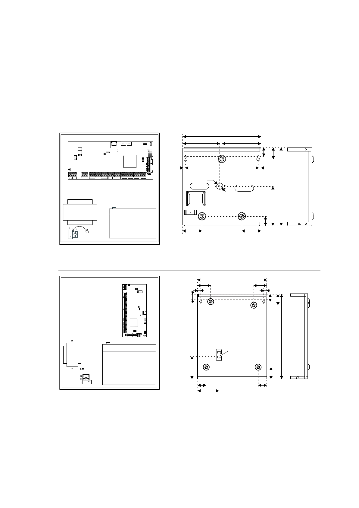
Advisor Advanced housings
The housings with mounting holes (items 1) are shown in figures below.
Item 2 indicates the pry-off tamper wall stub location.
All dimensions are given in mm.
Figure 1: Small metal housing (-SM)
Figure 2: Medium metal housing (-MM)
Advisor Advanced ATSx000A(-IP) Installation and Programming Manual 1
RxTx
USB
MI
IP
CON12
CON13
T1
T2
S4
S5
+
+
S1
C
+
S2
C
T C
+
+
- -
1 C 2 3 C 4 5 C 6 7 C 8
~
~
+ -
AC
BATT
LC-OUTPUTS
HC-OUTPUTS
SIR TMP AUX POW ER
INPUTS
CT
+
S3
C
CON16
NTC
COMMS
+12V0V D+ D-
259
129.5
73
403
54.5
45.5
73
395
50.5
70
126.5
41.5
70
253
()1
()1 ()1
RxTx
USB
MI
IP
CON12
CON13
T1
T2
S4
S5
+
+
S1
C
+
S2
C
T C
+
+
- -
1 C 2 3 C 4 5 C 6 7 C 8
~
~
+ -
AC
BATT
LC-OUTPUTS
HC-OUTPUTS
SIR TMP AUX POWER
INPUTS
CT
+
S3
C
CON16
NTC
COMMS
+12V0V D+ D-
256
227
128.5
11.7 11.7
7
91.6
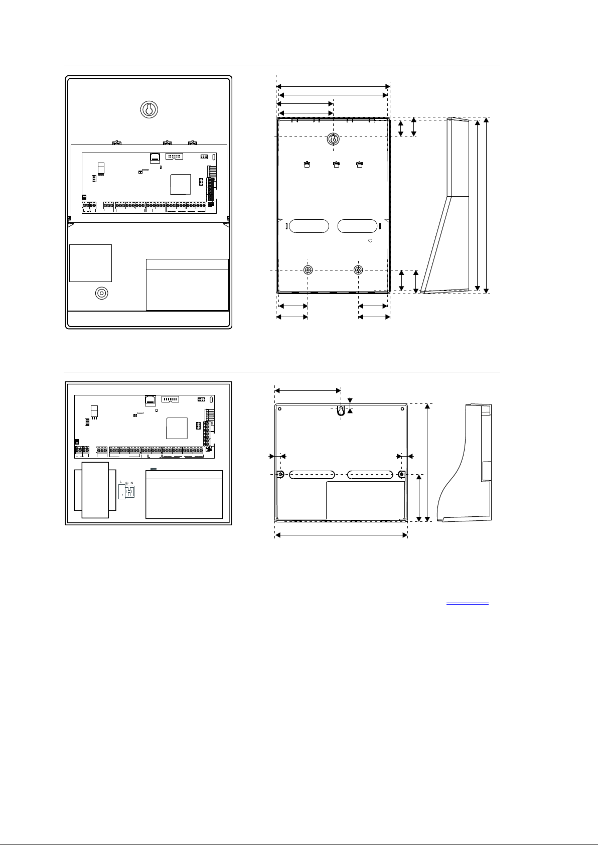
Figure 3: Large polycarbonate housing (-LP)
Figure 4: Small polycarbonate housing (-SP)
For more details on connections and connecting devices to the Advisor
Advanced, see “Cabling Advisor Advanced” on page 14.
For details on connecting pry-off tampers, see “Pry-off tamper mounting” below.
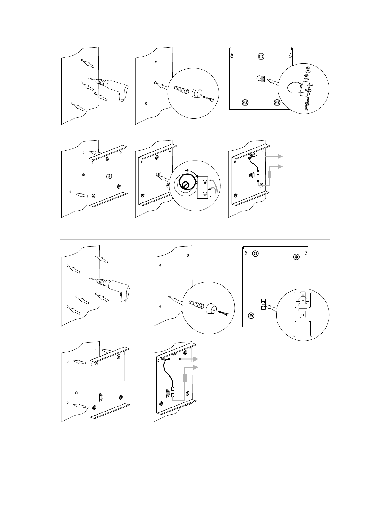
Pry-off tamper mounting
For small (-SM) housing, follow the steps in Figure 5 on page 3 to install pry-off
tamper. For medium (-MM) housing, follow the steps in Figure 6 on page 3.
2 Advisor Advanced ATSx000A(-IP) Installation and Programming Manual
COM
NO
COM
NO
C
T
TAMPER
A B C
D E F
COM NO
COM
NO
C
T
TAMPER
A B C
D E
Figure 5: Small (-SM) housing pry-off tamper mount
Figure 6: Medium(-MM) housing pry-off tamper mount
Advisor Advanced ATSx000A(-IP) Installation and Programming Manual 3
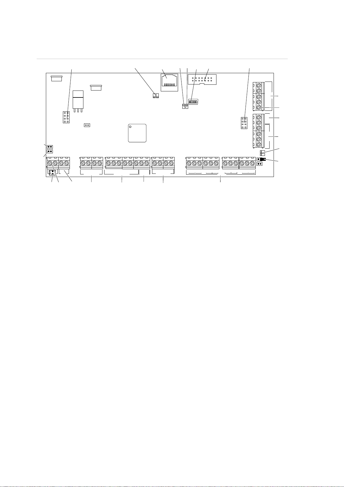
(1) Interface to output expander
(2) IP communication LED (ATS-IP only)
(3) Ethernet RJ-45 connector (ATS-IP only)
(4) USB fault LED
(5) USB power LED
(7) USB connector (mini-B type)
(8) MI-bus connector for MI devices
(9) Interface to input expander
(12) PSTN line connection and panel earth
terminal
(13) Panel earth terminal
(14) External tamper switch
(15) RS-485 system databus connections
(16) T2: Device firmware upgrade mode
(DFU)
(17) RS-485 system databus communication
LEDs
(18) T1: Restores the codes of master users
(installer and supervisor)
(19) System databus termination jumper
(20) AC power supply connector
(ATS1000A-SM only)
(21) AC power supply terminal
(22) Battery connection
(23) Low current (OC) outputs
(24) High current outputs
(25) Siren tamper switch
(26) 12 VDC auxiliary power output
(27) Zone inputs
(23)
(22)
(21)()20 (24) (25) (26) (27)
()2 ()3 ()4 ()7 (8) (9)
(1 )2
(1 )4
(1)
(1 )9
(1 )7
(1 )5
Rx
Tx
IP
USB
MI
IP
CON12
LK2
CON13
T1
T2
LK3
S3S4S5
+
+
S1
C
+
S2
C T C
+
+
- -
1 C 2 3 C 4 5 C 6 7 C 8
~~+
-
AC
BATT
LC-OUTPUTS
HC-OUTPUTS
SIR TMP
AUX POWER
INPUTS
Ax/R1
B/TA/R
EARTH
CTD-
D+
0V
+12V
COMMS
TAMPER
PSTN
(1 )8
(1 )6
()5
(13)
Advisor Advanced layout
Figure 7: Advisor Advanced ATSx000A(-IP) PCB layout
4 Advisor Advanced ATSx000A(-IP) Installation and Programming Manual
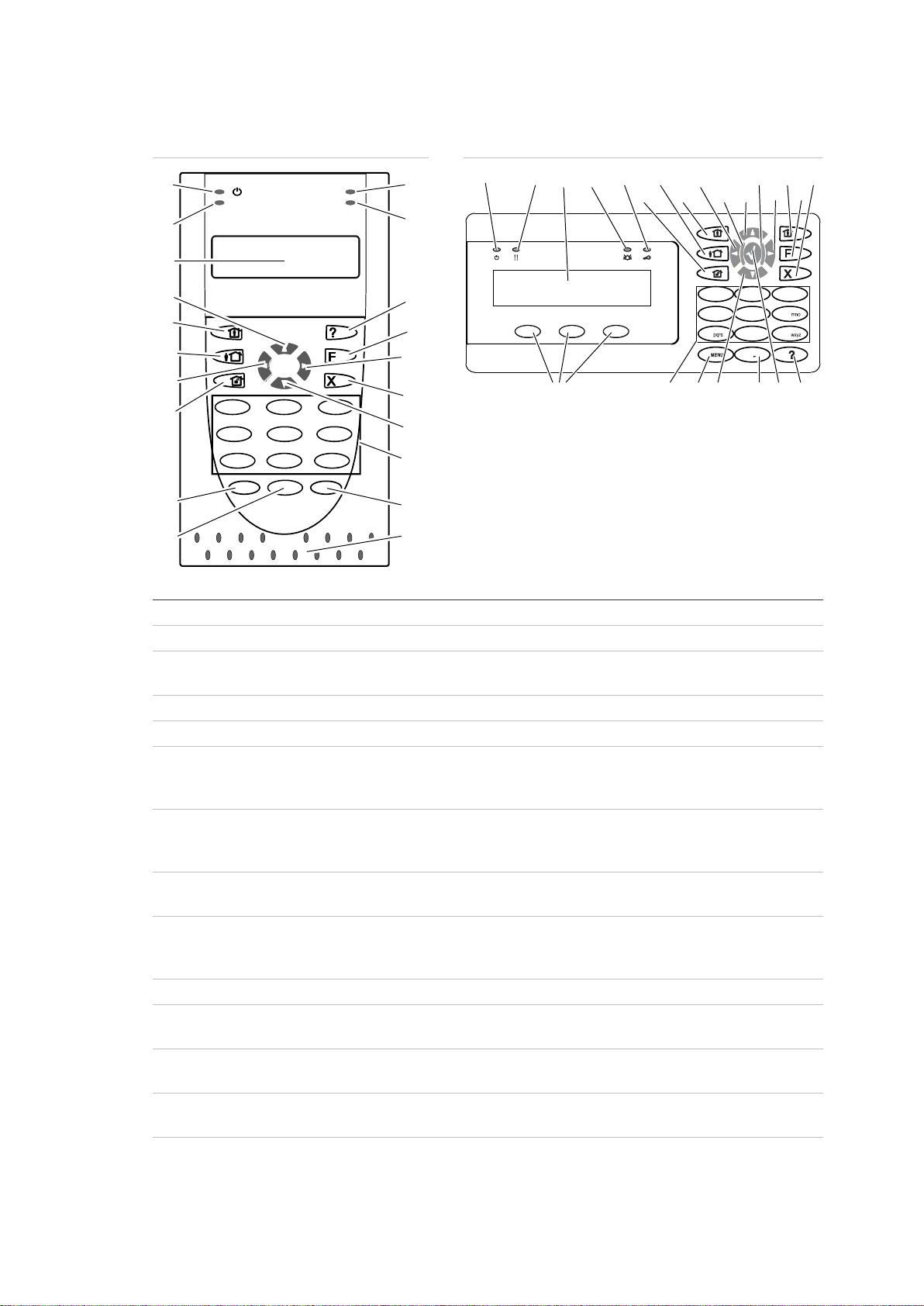
Figure 8: ATS111xA keypad
Figure 9: ATS1135 keypad
(1)
AC mains LED
Green on: AC mains supply on
(2)
Access LED
Blue flashes: card read
(3)
Fault LED
Yellow on: system fault active
Yellow flashing: general alert (EN 50131)
(4)
Alarm LED
Red on: alarm condition active
(5)
LCD display
Displays messages
(6)
/ Up
Scroll up in the menus
Change value
Delete
(7)
? / Help
Show help
Enable/disable word library
Scroll text (ATS113x only)
(8)
Partset
Part set an area
Scroll text (ATS111x only)
(9)
F / Function
Show active zones / faults
Function key modifier
Scroll text (ATS113x only)
(10)
On
Full set an area
(11)
/ Right
Enter the selected menu
Move cursor right
(12)
/ Left
Return to the previous menu
Move cursor left
(13)
X / Clear
Exit the current user function
Volume control modifier
(14)
Off
Unset an area
1
8
9
16
!!
3
21
4 6
5
7
98
0
*
Menu
#
Enter
(1)
(2)
(3)
(4)
(5)
(7)
(8)
(9)
(10)
(20)
(19)
(18)
(17)
(16)
(15)
(14)
(13)
(12)
(11)
(6)
0
12
3
4
5
6
789
12
abc
jkl
tuv
def
ghi
.,’?!
*
#
A B C
(1) (3) (6) (4) (2)
(14)
(10)
(21)
(12)
(6)
(18)
(11)
(22)
(9)
(13)
(23) (16) (17)(15) (19) (7)
(25)
(24)
Keypads and readers
Advisor Advanced ATSx000A(-IP) Installation and Programming Manual 5
(15)
/ Down
Scroll down in the menus
Change value
Backspace
(16)
Alphanumeric keys
Keys 1 to 9, alphanumerical data. See “Keypad layout” on page 40.
(17)
Menu
Request entry to the menus
(18)
Enter
Complete the step
Enter the selected menu entry
(19) 0 Key 0
Toggle selection
(20)
Area LEDs 1 to 16
On: area set
Off: area unset
Flashing: area alarm condition
(21)
Partset 1
Part set 1 of areas
(22)
Partset 2
Part set 2 of areas
(23)
A, B, C
Programmable function keys
(24)
LED1
Programmable LED 1
(25)
LED2
Programmable LED 2
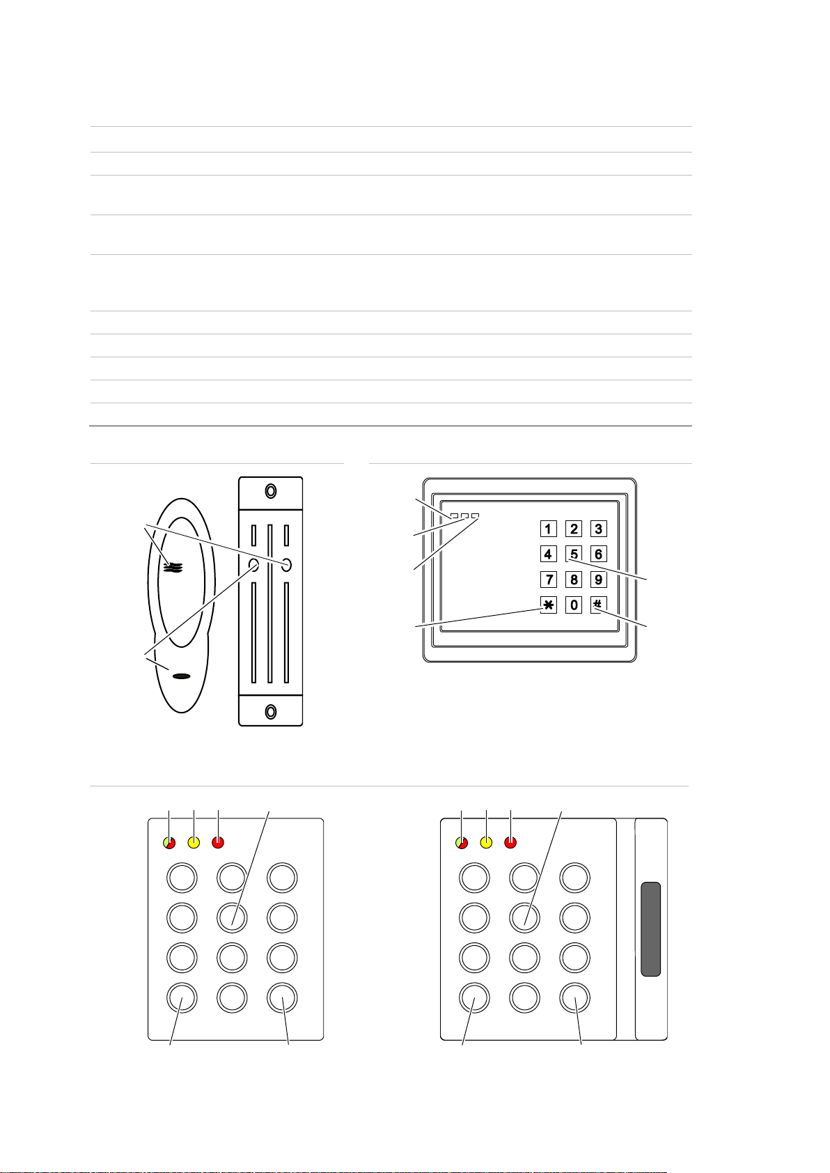
Figure 10: ATS1190/ATS1192 readers
Figure 11: ATS1197 reader with keypad
Figure 12: ATS1151/ATS1156 readers
(1)
(2)
OFF ON
(3)
(4)
(5)
(6)
(7)
(8)
1 2 3
4 5 6
7 8 9
*
0 #
(4) (5) (6)
(7) (8)
(3)
1 2 3
4 5 6
7 8 9
*
0 #
(3) (4) (5) (6)
(7) (8)
6 Advisor Advanced ATSx000A(-IP) Installation and Programming Manual

(1)
Blue LED
Access granted
(2)
Red LED
On: area set
Flashing: general alert (EN 50131)
(3)
Dual LED
Green on: AC mains supply on
Green flashing: AC mains supply off, or unlocked while unset
Red on: all areas set
Red flashing: unlocked while set
(4)
Yellow LED
On: All zones are in normal state
Flashing: general alert (EN 50131)
(5)
Red LED
Flashing: alarm
(6)
Numeric keys
Keys 0 to 9, numerical data
(7)
Off
Unset an area
(8)
On
Full set an area
Advisor Advanced ATSx000A(-IP) Installation and Programming Manual 7

Maintenance
Mains power connection
The intrusion control panel is only allowed to be serviced by dedicated service
personal. The screw of the housing is intended to protect the product from
unintended use.
For metal housing, the screw is already installed out of the box. For plastic
housing, the screw, available inside housing, should be mounted before first time
use.
Use the mains connector terminal for connecting the AC mains supply. A fixed
cable or flexible mains lead to earthed mains outlet can be used. When fixed
wiring is used, insert a dedicated circuit breaker in the power distribution network.
In all cases the mains connection must comply with local regulations.
In case the panel is connected to the power grid using fixed wiring, it is
recommended that earth wire is longer than line and neutral.
Do connect incoming line and neutral to mains connection block according to the
label. This assures that the line will be protected by the mains fuse, and that
service can be done by service personnel.
Make sure that before connecting the mains power, the mains power supply is
disconnected.
When installing the mains power, use strain reliefs such as cable ties and
coupling PG16s to ensure proper wiring. . If product entry hole breakouts are
used, it is required to also make use of UL-V2 (or better) approved PG16 cable
gland. Refer to PG16 specification to meet minimum and maximum cable
diameters.
In all cases local regulations must be observed.
WARNING: Electrocution hazard. To avoid personal injury or death from
electrocution, remove all sources of power and allow stored energy to discharge
before installing or removing equipment.
Battery replacement
This product may contain one (or more) sealed, rechargeable, BS-type lead-acid
battery. Because removing a battery may affect the product’s configuration
settings or trigger an alarm, only a qualified installer should remove the batteries.
To remove a battery:
1. Make sure that your product settings allow you to open the cover without
starting the tamper alarm.
2. Switch off the mains power, if necessary, and remove the cover.
8 Advisor Advanced ATSx000A(-IP) Installation and Programming Manual

3. Disconnect the battery. Note that depending on the battery model the connectors may be located differently.
4. Remove the battery from the holder.
In case a battery BS131 (12 V / 18 Ah) in an ATS1640 housing is used, it is
required to have double insulation in place. Use adequately insulated wires for
PSTN cabling, and make use of heat shrink.
Dispose of the battery as required by local ordinances or regulations.
See the specifications for your product or contact technical support for
information on replacement batteries.
Advisor Advanced ATSx000A(-IP) Installation and Programming Manual 9

Mounting
The unit is mounted with screws or bolts through the mounting holes in the rear
section of the enclosure.
Important: When the product is mounted to the wall, assure that at least
3 times the weight of the product can be supported. The product weight is the
product itself plus battery and accessories.
Ensure that the unit is mounted on a flat, solid, vertical surface such that the
base will not flex or warp when the mounting screws and bolts are tightened.
Leave a 50 mm clearance between equipment enclosures mounted side by side
and 25 mm between the enclosure and the sidewall.
The rechargeable battery must not be fitted until the control panel is secured to
the fixing surface. Under no circumstances should the panel be transported with
a battery fitted.
Take care that wire terminals are isolated. The use of cable ties to neatly secure
cables is recommended.
General installation guidelines
The Advisor Advanced control panels have been designed, assembled, and
tested to meet the requirements of current relevant standards for safety,
emission, and immunity to environmental electrical and electromagnetic
interference.
If the following guidelines are followed, the system will give many years of
reliable service.
In addition to the following guidelines, during the installation of the Advisor
Advanced control panel, it is essential to follow any country-dependent local
standard requirements applicable to the installation. Only a qualified electrician or
other suitably trained and qualified person should attempt to wire this system to
the AC mains or to the public telephone network.
• Ensure that there is a good earth available for the alarm system.
• Maintain a separation between low voltage and mains supply cables. Use
separate points of cable entry to the control panel cabinet.
• If the upper and/or lower cabinet entry cable holes are used to route wiring
into the control panel, always use a proper pipe fitting system by means of an
appropriate conduit and junction box. For this purpose, use only materials of
suitable flammability class (HB or better).
• For mains power connection, use the mains connector terminal either through
a permanent wiring or a flexible mains cable to an earthed mains outlet.
Always use cable ties to fix the mains cable at the dedicated fixing point
provided near the mains terminal connector.
10 Advisor Advanced ATSx000A(-IP) Installation and Programming Manual

- When installing permanent, fixed wiring, insert an easily accessible,
dedicated bipolar circuit breaker in the power distribution network.
- Never attempt to solder mains connection wires at the ends where they will
be wired to the terminal connectors.
• Avoid loops of wire inside the control panel cabinet and route cables so that
they do not lie on top or underneath of the printed circuit board. The use of
cable ties is recommended and improves neatness of the wiring within the
box.
• The battery used with this unit, must be made of materials of suitable
flammability class (HB or better).
• Any circuit connected either directly to the onboard relay contacts or to the
external relay contacts through the onboard electronic output must be rated
as a SELV (safety extra-low voltage) operating circuit.
- A mains switching relay must not be fitted inside the control panel cabinet.
- Always place a suppression diode (e.g. a 1N4001) across the relay coil.
- Use only relays with good insulation between the contacts and the coil.
- Maximum cable length for open collector output connection may not exceed
30 m. For longer distances, use relay output expansion (for example, ATS624
four-relay expander).
• The minimum clearance between equipment closures is 50 mm (between
equipment vents).
• Only use these units in a clean environment and not in humid air.
Environmental requirements are given in “Specifications” on page 25.
• For the panel terminal connections, the recommended torque is 0,3 to
0,4 N·m. This torque setting is independent from the AWG (thickness) of the
wires used. A value of 0,4 N·m is also the maximum allowed torque for this
connector.
Advisor Advanced ATSx000A(-IP) Installation and Programming Manual 11

Earthing
WARNING: The correct earthing procedures must be followed.
Earthing of one cabinet containing several devices
All devices designed for the system have earth connections via metal studs to
the metal housing. Make sure that these metal studs make good connection to
the housing (beware of paint). The earth connections of every piece of equipment
in the system can be used for connecting the screen of shielded cables.
If a device is placed in a plastic housing the earth lug of the device does not have
to be connected.
Earthing panels in a single building
In one building several cabinets or devices are earthed to a safety ground.
The safety ground for the building must be checked by a licensed contractor.
Earthing panels in more buildings
If the wiring extends to separate buildings, more than one common earth system
will be used. Use ATS1740 isolator/repeaters to isolate the system databus. In
this way the system is protected against variations in earth potential.
12 Advisor Advanced ATSx000A(-IP) Installation and Programming Manual
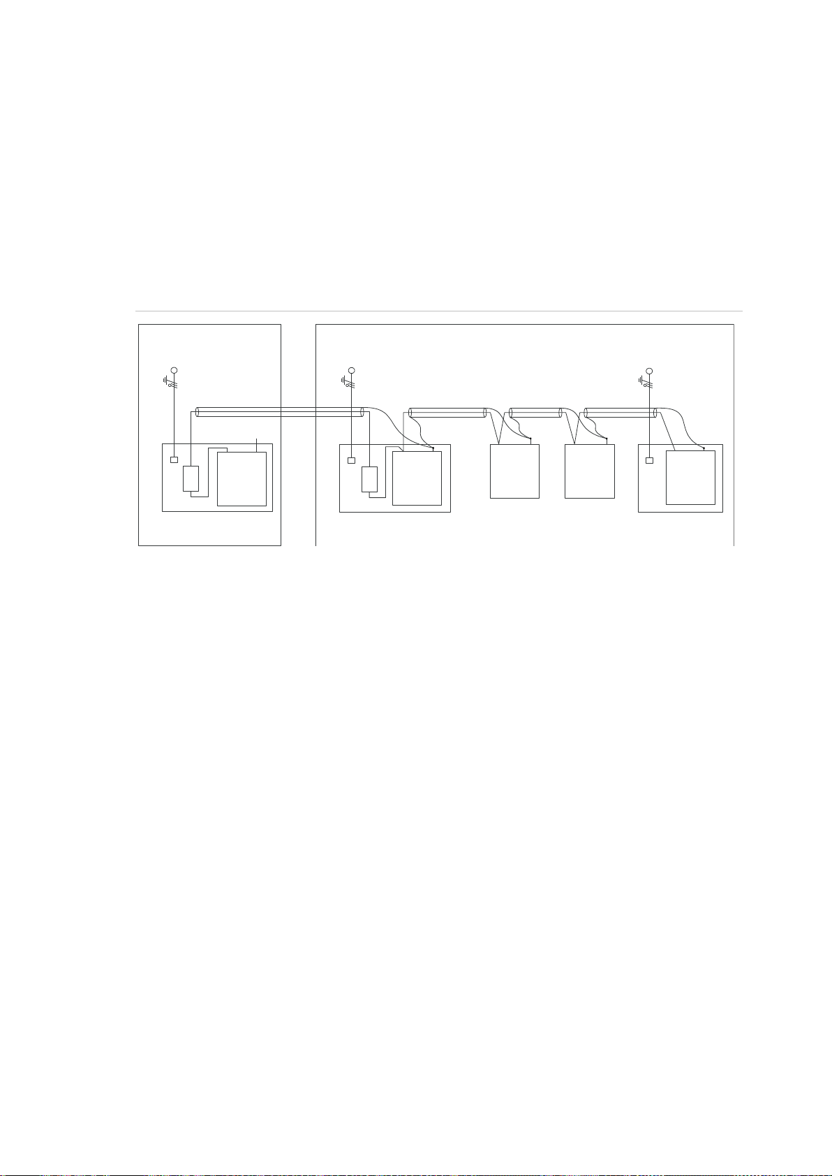
(1) Building 1
(2) Building 2
(3) Mains power with local earth
(4) Earth and shielding
(5) Mains power connector
(6) Advisor Advanced control panel
(7) System databus
(8) Device in plastic housing
(9) Device in metal housing
1740
ATS1201(E)
1740
Advisor
Advanced
ATS1210(E)
ATS1135
ATS1203(E)
(1)
(2)
(3)
(4)
(5)
(6)
(7)
(3)
(3)
(4)
(4)
(4)
(4)
(5)
(5)
(7)
(7)
(8)
(9)
(8)
(9)
(9)
Shielding
The shielding of all shielded cables used in the system should only be connected
at one side to one common earthing point in a building (see Figure 13 below). If a
shielded databus cable is routed via more than one plastic device the shielding
from incoming and outgoing cable must be connected.
In case the IP connection is used, take care that the Ethernet FTP cable remains
within a single building. Do make use of a proper router or switcher to isolate
Ethernet cables between various buildings.
Figure 13: System shielding
Advisor Advanced ATSx000A(-IP) Installation and Programming Manual 13
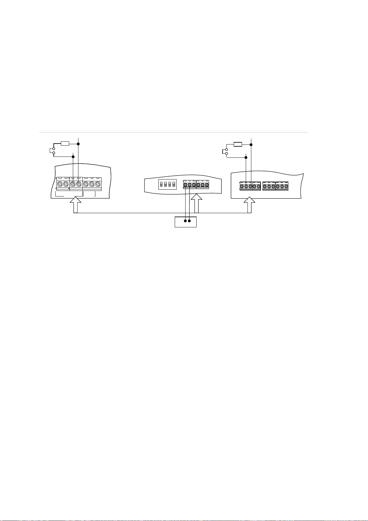
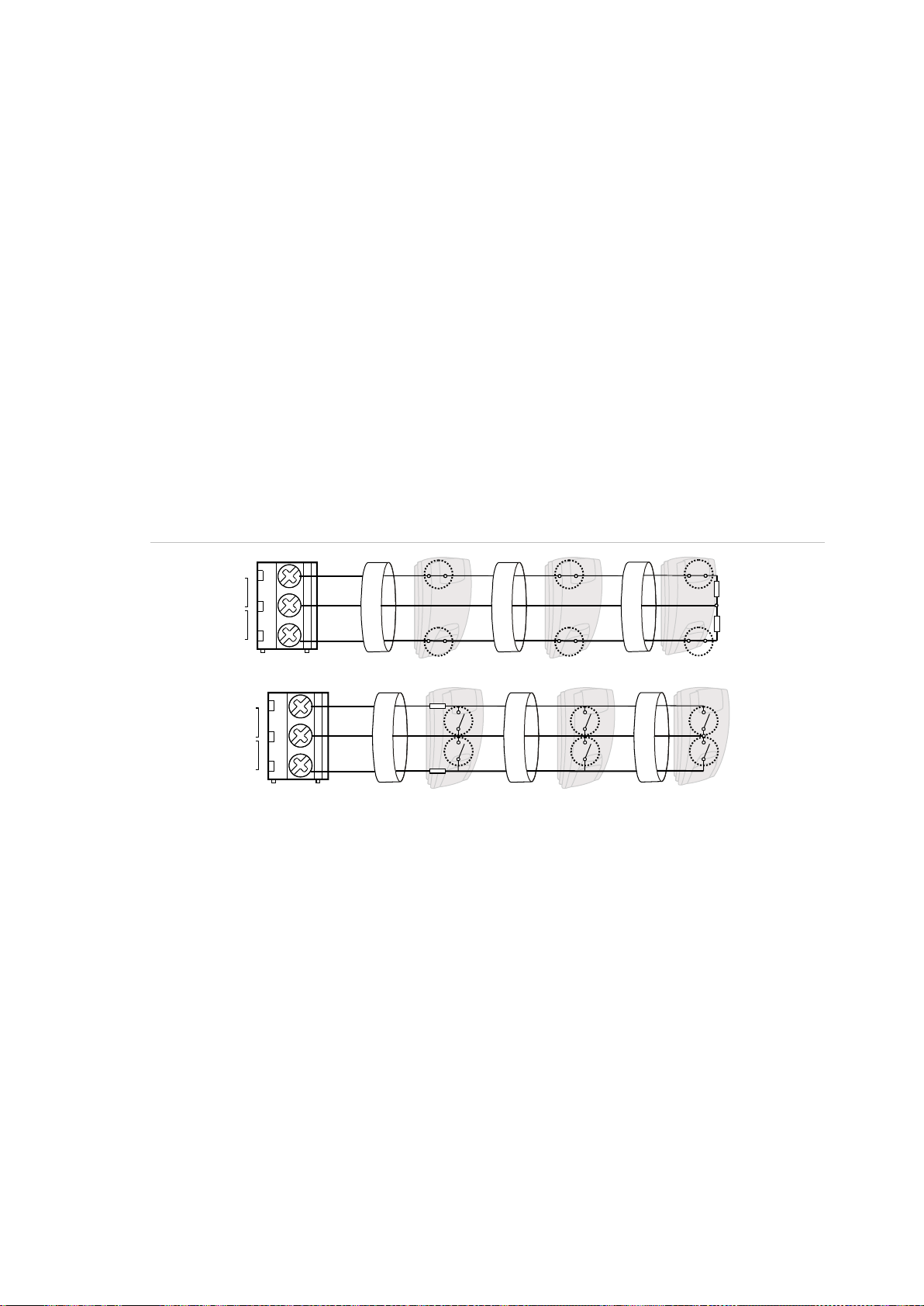
(1) TERM link fitted (first device on local
databus).
(2) Advisor Advanced control panel
variants.
(3) Preferred data cable type is WCAT 52
(two twisted pairs).
(4) Advisor LCD keypad (TERM switch is
set to OFF).
(5) Separate 12 V power supply (required if
keypad is more than 100 m from the
nearest panel or expander. Connect the
negative terminal of the power supply to
the “−” wire of the databus.
(6) TERM link fitted (last device on local
databus).
(7) Any remote expander like ATS1201(E) or
ATS1210(E).
D+0V+12V D- IN OUT
CTD-D+
-
1 C 2 C 3 C
470 ohm
+ -
470 ohm
(1)
(2)
(3)
(5)
(4)
(6)
(7)
EARTH
CTD-
D+
0V
12V
COMMS
TAMPER
Cabling Advisor Advanced
System databus preferred wiring
The terminator jumper (also called TERM link), or DIP switch must be ON, or a
470 Ω resistor must be fitted at each of the devices at the extreme ends of the
daisy chained databus. In a star-wiring configuration, the TERM link is only fitted
on the devices at the ends of the two longest system databus cable runs.
Figure 14: System databus wiring
System databus connection
The system databus is used to connect remote expanders (to provide extra
zones) and keypads to the Advisor Advanced control panel. Remote devices can
be up to 1.5 km from an Advisor Advanced control panel.
Keypads and remote expanders must be connected via a shielded data cable
with two twisted-pairs from the system databus connection (WCAT 52 is
recommended).
We recommend that you use a separate power supply for a keypad when the
distance between that keypad and the nearest device is more than 100 meters.
If the keypad is powered with a separate power supply, do not connect “+” from
the system databus. Connect “+” of the local power supply to “+” on the keypad,
and connect 0 volts from the power supply and 0 volts from the system databus
to the keypad terminal marked “−”. The maximum number of devices allowed on
the databus is given in “General features” on page 26.
14 Advisor Advanced ATSx000A(-IP) Installation and Programming Manual
(1) Zone terminal
C Common terminal
Z1 Zone 1 input
Z2 Zone 2 input
(2) Detector
A Alarm relay
T Tamper relay
C
(1)
T
()2
RA
Z2Z1
A A A
T T
RT
()2 ()2
C
(1)
A
T
()2
RA
Z2Z1
RT
()2 ()2
A
T
A
T
Zone connection
The inputs are set up as standard EOL freely programmable zones. However, by
programming the zones as dual loop, all zone inputs can be programmed to give
a few states indication for the same zone.
Depending on the detector model, do the following to set up zones:
• Choose your EOL connection type. See “EOL connection types” on page 19.
• Program input mode. See “8.5.1 Input mode” on page 152 for the panel, or
“2.2.2.n.4.4 Input mode” on page 76 for expanders.
• Set end-of-line resistor values. See “8.5.2 EOL” on page 152 for the panel, or
“2.2.2.n.4.5 EOL” on page 76 for expanders.
• Configure anti-masking option. See “4.1.n.6.6 Anti mask” on page 98.
Single loop zone wiring
In single loop zone wiring, two zones are required, one zone for alarm and one
zone for tamper. The tamper contacts are wired in series with an EOL resistor.
Figure 15: Single loop examples
Dual loop zone wiring
In dual loop wiring, one zone can detect a few detector states. At least two
resistors are used to define alarm and tamper states. Depending on the
programmed settings, there can be additional states defined as masking alarm or
sensor fault. These states can be the following:
• Short (tamper)
• Active (alarm)
• Normal
• Masking
• Sensor fault
• Open (tamper)
Advisor Advanced ATSx000A(-IP) Installation and Programming Manual 15

(1) Zone terminal
C Common terminal
Z1 Zone 1 input
Z2 Zone 2 input
(2) Detector
A Alarm relay
T Tamper relay
Zone state
EOL
Connection
details [1]
Measure [2]
Short
Masking
Normal
Alarm
Fault
Open
Single NC
(Item 1)
No EOL
R (kΩ)
— — <1
>1 — —
U (V)
— — <3.5
>3.5
—
—
Note: Values for other EOL are equal to Dual, except all ranges but normal are
alarm ranges.
Single NO
(Item 2)
No EOL
R (kΩ)
— — >44.70
<44.70
— — U (V)
— — >11.14
<11.14
—
—
Note: Values for other EOL are equal to Dual, except all ranges but normal are
alarm ranges.
Dual
10K
(Item 4)
R (kΩ)
<3.33
3.33–
6.67
6.67–
13.33
13.33–
26.67
—
>26.67
RA=10 kΩ, RT=5 kΩ,
RF=5 kΩ
U (V)
<5.70
5.70–
8.10
8.10–
10.20
10.20–
11.70
—
>11.70
4K7
(Item 3)
R (kΩ)
<1.00
—
1.00–
6.67
6.67–
16.84
—
>16.84
RA=4.7 kΩ, RT=4.7 kΩ
U (V)
<2.41
—
2.41–
8.07
8.07–
10.74
—
>10.74
C
Z2
(1)
RA
A
()2
RT
T
Z1
A A
T T
()2 ()2
Figure 16: Dual loop example
Possible EOL connections are listed in “EOL connection types” on page 19.
Values for end-of-line resistors
The following list contains the values for end-of-line resistors and possible zone
states. Both the resistance and the voltage measured across the zone are
shown.
Depending on the input type and anti-masking option, the following EOL values
can be available.
16 Advisor Advanced ATSx000A(-IP) Installation and Programming Manual

Zone state
EOL
Connection
details [1]
Measure [2]
Short
Masking
Normal
Alarm
Fault
Open
4K7
(Item 4)
R (kΩ)
<1.00
1.00–
3.42
3.42–
6.67
6.67–
16.84
—
>16.84
RA=4.7 kΩ, RT=2.35 kΩ,
RF=2.35 kΩ
U (V)
<2.41
2.41–
5.79
5.79–
8.07
8.07–
10.74
—
>10.74
4K7
(Item 7)
R (kΩ)
<1.00
16.84–
55.00
1.00–
6.67
6.67–
11.75
11.75–
16.84
>55.00
RA=4.7 kΩ, RT=4.7 kΩ,
RF=10 kΩ
U (V)
<2.41
10.74–
12.70
2.41–
8.07
8.07–
9.82
9.82–
10.74
>12.70
2K2
(Item 4)
R (kΩ)
<0.73
0.73–
1.47
1.47–
2.93
2.93–
5.87
—
>5.87
RA=2.2 kΩ, RT=1.1 kΩ,
RF=1.1 kΩ
U (V)
<1.90
1.90–
3.30
3.30–
5.30
5.30–
7.70
—
>7.70
6K8
(Item 4)
R (kΩ)
<2.27
2.27–
4.53
4.53–
9.07
9.07–
18.13
—
>18.13
RA=6.8 kΩ, RT=3.4 kΩ,
RF=3.4 kΩ
U (V)
<4.50
4.50–
6.80
6.80–
9.10
9.10–
11.00
—
>11.00
5K6
(Item 4)
R (kΩ)
<1.87
1.87–
3.73
3.73–
7.47
7.47–
14.93
—
>14.93
RA=5.6 kΩ, RT=2.8 kΩ,
RF=2.8 kΩ
U (V)
<3.90
3.90–
6.10
6.10–
8.50
8.50–
10.50
—
>10.50
3K74
(Item 4)
R (kΩ)
<1.25
1.25–
2.45
2.45–
4.99
4.99–
9.98
—
>9.98
RA=3.74 kΩ, RT=1.87 kΩ,
RF=1.87 kΩ
U (V)
<2.90
2.90–
4.80
4.80–
7.10
7.10–
9.40
—
>9.40
3K3
(Item 4)
R (kΩ)
<1.10
1.10–
2.20
2.20–
4.40
4.40–
8.80
—
>8.80
RA=3.3 kΩ, RT=1.65 kΩ,
RF=1.65 kΩ
U (V)
<2.60
2.60–
4.40
4.40–
6.70
6.70–
9.00
—
>9.00
2K
(Item 4)
R (kΩ)
<0.67
0.67–
1.33
1.33–
2.67
2.67–
5.33
—
>5.33
RA=2 kΩ, RT=1 kΩ,
RF=1 kΩ
U (V)
<1.70
1.70–
3.00
3.00–
5.00
5.00–
7.30
—
>7.30
1K5
(Item 4)
R (kΩ)
<0.50
0.50–
1.00
1.00–
2.00
2.00–
4.00
—
>4.00
RA=1.5 kΩ, RT=0.75 kΩ,
RF=0.75 kΩ
U (V)
<1.30
1.30–
2.40
2.40–
4.10
4.10–
6.30
—
>6.30
2K2+4K7
(Item 3)
R (kΩ)
<3.60
—
3.60–
5.60
5.60–
8.20
—
>8.20
RA=2.2 kΩ, RT=4.7 kΩ
U (V)
<6.00
—
6.00–
7.50
7.50–
8.80
>8.80
Advisor Advanced ATSx000A(-IP) Installation and Programming Manual 17

Zone state
EOL
Connection
details [1]
Measure [2]
Short
Masking
Normal
Alarm
Fault
Open
1K
(Item 7)
R (kΩ)
<0.51
4.52–
40.00
0.51–
1.52
1.52–
2.94
2.94–
4.52
>40.00
RA=1 kΩ, RT=1 kΩ,
RF=12 kΩ
U (V)
<1.35
6.24–
12.33
1.35–
3.36
3.36–
5.29
5.29–
6.74
>12.33
8K2
(Item 5)
R (kΩ)
<1.50
—
1.50–
5.84
5.84–
14.25
—
>14.25
RA=8.2 kΩ, RT=8.2 kΩ
U (V)
<3.33
—
3.33–
7.52
7.52–
10.33
—
>10.33
8K2
(Item 6)
R (kΩ)
<1.50
14.25–
45.00
1.50–
5.84
5.84–
10.07
10.07–
14.25
>45.00
RA=8.2 kΩ, RT=8.2 kΩ,
RF=8.2 kΩ
U (V)
<3.33
10.33–
12.48
3.33–
7.52
7.52–
9.37
9.37–
10.33
>12.48
[1] Refer to Figure 17 on page 19.
[2] Zone resistance R (kΩ), zone voltage U (V).
— The state is not available
18 Advisor Advanced ATSx000A(-IP) Installation and Programming Manual

(1) Single NC
(2) Single NO
(3) Dual A (default)
(4) Dual A with AM
(5) Dual B
(6) Dual C with AM
(7) Dual D with AM
A Alarm relay
T Tamper relay
F Fault / Anti-mask alarm relay
RA Alarm resistor
RT Tamper resistor
RF Fault / Anti-mask alarm resistor
RA
C
Z1
A
C
Z1
RA
A
A
RA
RT
C
Z1
T
A
T
RA
RF
C
Z1
F
RT
ART
RA
C
Z1
T
A
F
RF
RA
RT
C
Z1
T
A
F
RA
RF
RT
C
Z1
T
EOL connection types
The following EOL connections are used for different input types and EOL
values. See “Values for end-of-line resistors” on page 16 for more details.
Figure 17: Connection type
Caution: When using connection types (4), (6) and (7), the antimask option of
the zone must be enabled. Other zones must have this option disabled. See
“4.1.n.6.6 Anti mask” on page 98.
Advisor Advanced ATSx000A(-IP) Installation and Programming Manual 19
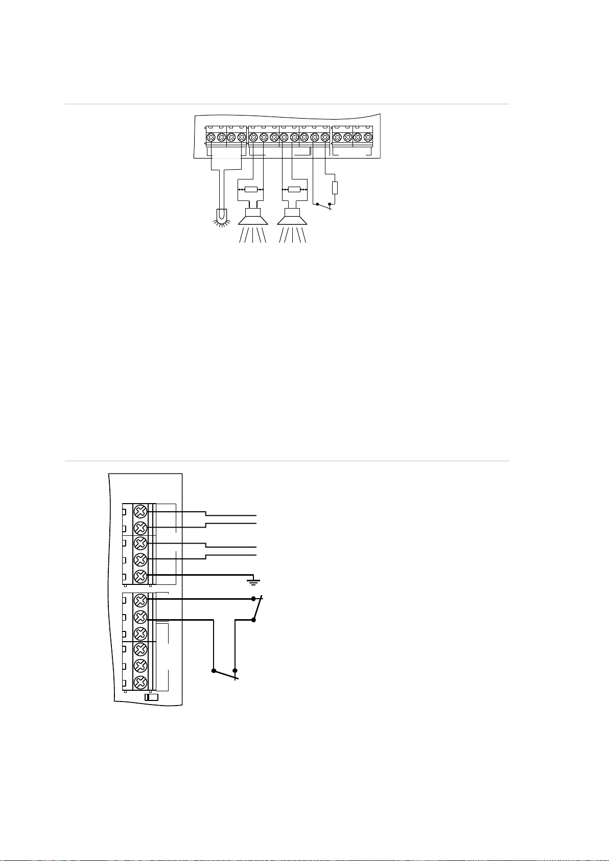
(1) Siren EOL resistor (1 kΩ). It must be
installed if siren does not contain a
built-in resistor.
(2) Siren.
(3) Beacon, maximum 50 mA.
(4) Siren tamper EOL resistor.
(5) Siren tamper (normally closed).
(1) Phone (switched)
(2) PSTN line
(3) Earthing
(4) External tamper (normally closed)
(5) Optional pry-off tamper (normally
closed) required by EN 50131
Grade 3 and VdS-C regulations
+
+
S1
C
+
S2
C T C
+
+
- -
LC-OUTPUTS
HC-OUTPUTS SIR TMP AUX POWER
S3S4S5
(1)
(2)
(3)
(4)
(5)
(1)
(2)
Tx
Ax/R1
B/TA/R
EARTH
CTD-
D+
0V
+12V
COMMS
TAMPER
PSTN
(1)
(2)
(3)
(4)
()5
Siren connection
Figure 18: Siren connection examples
Note: Siren output can be configured as internal or external. This is accomplished via panel
settings, not by configuring the panel hardware. See “Default output assignments” on page 23
and “Filters, outputs, and triggers” on page 116.
Other connections
Tamper connection
Figure 19: Earthing, external tamper, and PSTN connection in ATSx000A(-IP)
PSTN connection
For ATSx000A(-IP), refer to Figure 19 above.
20 Advisor Advanced ATSx000A(-IP) Installation and Programming Manual
 Loading...