

Page 1
AP750-ID Installation Instructions
Description
The AP750-ID is an addressable PIR device that interfaces
with the PinPoint® system. This system provides flexible and
reliable two-way communication between the device and the
controller.
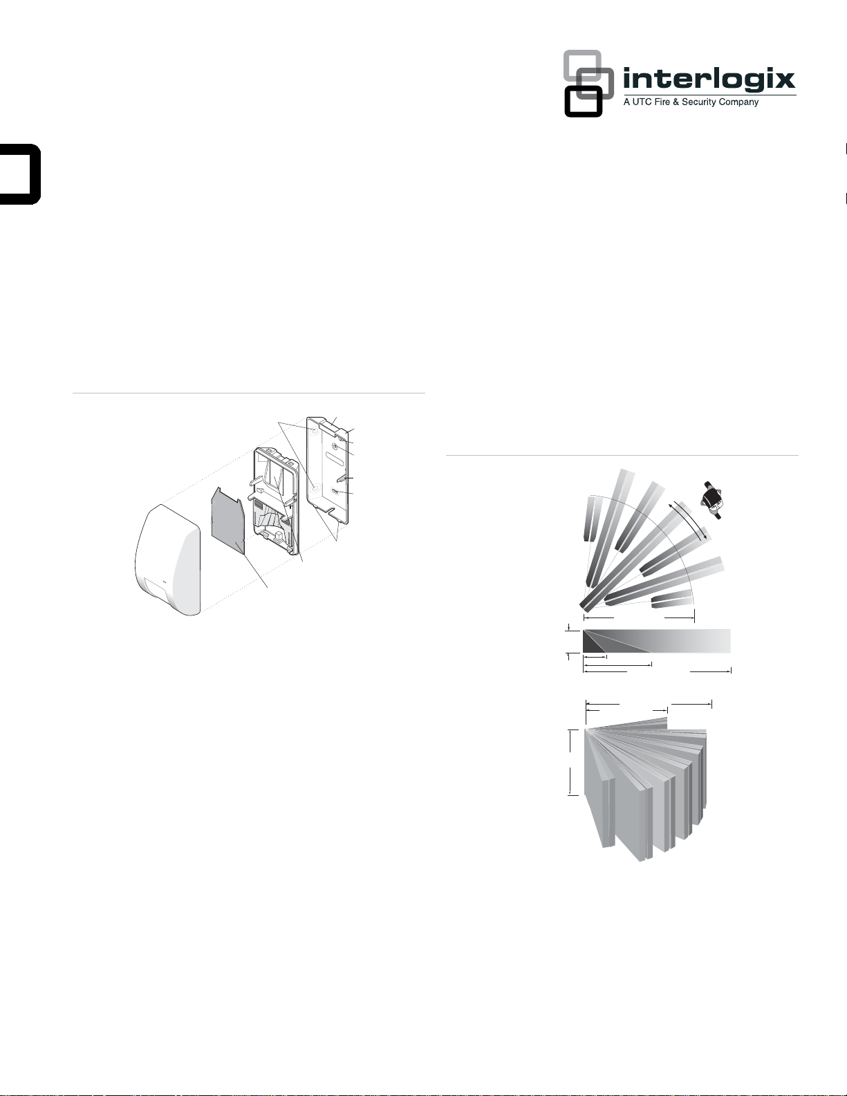
Figure 1: Exploded view
1
10
1 - Corner mounting knockouts
2 - Base indent
3 - Wall mounting bracket
4 - Flat wall mounting knockout
5 - Cable entry
6 - Tamper actuator
7 - Flat wall mounting knockout
8 - Tabs
9 - Wiring access
10 - Circuit board
2
3
4
5
6
7
8
9
Selecting a location
Mount the unit:
• On a rigid vibration-free surface.
• 6 to 10 feet (1.8 to 3m) high, but at least 6 inches (15cm)
from the ceiling.
• So the expected movement of an intruder is across the
fields of the detection pattern. See Figure 2 below.
Figure 2: Detection pattern
33.0 ft.(10.1m)
10.0 ft.(3.0m) maximum
8.0 ft.(2.4m) nominal
6.0 ft.(1.8m) minimum
8.0 ft.(2.4m)
50.0 ft.(15.2m)
33.0 ft.(10.1m)
25.0 ft.(7.6m)
50.0 ft.(15.2m)
10.0 ft.(3.0m)
Parts included
• PIR detector
• Two plastic masks
• One screw to secure the to the wall mounting bracket
• Wall mounting bracket
• Sheet of adhesive masking labels
• Cardboard undercrawl window mask
Do not locate the unit:
• On a surface exposed to moisture.
• Where it may be exposed to false alarm sources such as:
direct sunlight, heat sources (heater, radiators, etc.) in the
field of view, strong air drafts (fans, air conditioner, etc.).
P/N 1036045 • REV C • 16MAY11 1
Page 2

• Where the ambient temperature is below 32° F (0°C) or
above 131°F (55°C).
Mounting the unit
1. Separate the PIR unit from the mounting bracket by
inserting a small, flat-bladed screwdriver between the tabs
at the bottom of the unit and turning the screwdriver to
push the tabs apart. See Figure 1 on page 1.
ution: You must be free of static electricity before handling
Ca
sensor circuit boards. Touch a grounded, bare metal surface
before touching circuit boards or wear a grounding strap.
2. Select the coverage pattern and set the sensitivity and
range switches. See Figure 6 on page 3, Selecting the
age Pattern, and Setting the Sensitivity and Range
Cover
Switches.
3. Set the PinPoint address DIP switches. See Figure 6 on
page 3.
If necessar
y, use one or more of the following methods to
modify the coverage pattern:
• Use one or both of the plastic masks provided to mask off
large areas of coverage as shown in Figure 3 below.
Mask the appropriate mirror curtains with the adhesive
•
labels provided. See the example shown in Figure 4
below. Do not use shar
p objects to remove unwanted
labels. If necessary, carefully peel the label off.
• Use the cardboard undercrawl window mask as shown in
Figure 5 below. The undercrawl mask allows objects to be
ed within 5 feet of, or directly below, the detector.
plac
Figure 3: Plastic masks
1
2
Note: Units are shipped with DIP switches set to 255. This
is an invalid address. The unit will not communicate with
the control panel until a valid address has been set. Refer
to the NX-2192 manual to determine the correct address
setting for each unit.
4. Remove the appropriate knockout mounting and wiring
holes on the mounting bracket for either corner or flat wall
mounting and PinPoint wiring.
Note: Holes near the tamper actuator are not mounting
knockouts.
5. Pull the PinPoint wiring through the wiring knockout hole.
Use screws and wall anchors, if necessary, to attach the
mounting bracket to the wall. Do not over-tighten.
6. Strip 1/4 inch (6.4mm) of insulation from the PinPoint
wires. Connect the wiring to the appropriate screw
terminals and tighten the screws. See Figure 6 on page 3.
Be careful not to catch the wiring as you snap the unit to
7.
the mounting bracket.
8. Test the unit when the PinPoint system is completely
installed and the control panel is powered.
1
Figure 4: Adhesive labels
A
B
B
7
6
Figure 5: Undercrawl mask
1
324567
2
1
2 3 4567
A
5
4
2
1
2
3
Selecting the coverage pattern
The coverage pattern for the unit can be modified to fit specific
applications by masking off mirror curtains. Curtains should be
masked to avoid sources of false alarms, such as heaters, air
conditioners, and windows. Open the unit by pushing the
opening tab up. See Figure 6 on page 3.
2 AP750-ID Installation Instructions
7.9 ft
(2.4m)
5.0 ft
(1.5m)
Page 3

6: Detector back
ON APEMS
1 2 3 4 5 6 7 8
Figure
Tamper switch
OUT IN
- + - +
ON APEMS
Opening tab
Terminal block
DIP switches
Switch settings:
33'(10.1m) STD
Note: T
he LED only lights if the unit is placed in Walktest
Mode by the installer and the unit is enrolled in the
system.
Walk testing
A Walktest Mode for testing the unit operation and coverage
pattern is provided. Use the following instructions to walk test
the unit:
50'( 15.2m ) BI
Setting the sensitivity and range switches
There are switches on the back of the unit for setting sensitivity
and range, as shown in Figure 6 above.
Use the foll
for an application:
Mode
owing to determine the appropriate switch settings
BI=Bi-curtain Mode (factory default) increases false
alarm immunity in smaller areas and requires the intruder
to pass through two curtains to trigger an alarm. Do not
use for single curtain applications or ranges under 5 feet
(1.5m).
STD=Standard Mode is used for wide-angle or singlecurtain applications. It requires the intruder to only pass
through one curtain to trigger an alarm.
1. Ensure the unit is enrolled in the PinPoint system.
2. Lift the unit from the bracket until the tamper switch opens
to enable the Walktest Mode.
3. When the unit is remounted on the bracket, the unit
remains in the Walktest Mode for 3-4 minutes. If additional
time is required, depressing and releasing the tamper
switch will reset the Walktest timer. Depending on switch
settings (see “Selecting the coverage pattern” on page 2),
alktest Mode allows the unit to alarm whenever one
the W
or two curtain areas are entered. The LED visible on the
front cover lights to indicate an alarm.
4. Walk test the detection pattern and make any necessary
adjustments.
5. Replace and walk test the unit to verify the unit is
communicating with the control panel.
Note: After Walktest Mode times out (3 to 4 minutes), the
unit returns to normal operating mode. In normal operating
mode, the unit will alarm no more often than once every 3
minutes, and the LED is disabled to reduce voltage loss
on the PinPoint bus.
Maintenance
Note: Operation in the Standard Curtain Mode is UL 639
Listed for the specified ranges of 33 feet (10.1m) and 50
feet (15.2m). For operation in Bi-curtain Mode, the unit is
UL 639 Listed for 30 feet (9.1m) of range only. For ranges
from 30 to 50 feet (9.1 to 15.2m), the unit is not UL 639
Listed but will provide detection within 6 steps or 14 feet
(4.3m) across the plane of coverage. UL has not tested
the 6 steps or 14 foot (4.3m) detection.
When installed and used properly, the unit provides years of
service with minimal maintenance. To ensure proper operation,
you should walk test the unit annually as described in Walk
Testing.
Clean the inside of the unit with a soft bristled brush or
compressed air. Clean the cover with a damp (water) cloth as
needed to keep it free of dust and dirt. Always test the unit
after cleaning.
Range
Program switch for range under 33 feet (10.1m) (factory
default) or to 50 feet (15.2m). It's important to program the
unit correctly for optimum sensitivity. Walk test the unit
regularly by walking across the fields of view and checking
that the LED lights and that an alarm is indicated at the
control panel. See “Walk testing” below.
AP750-ID Installation Instructions 3
Pet alley application
To create a detection-free area close to the floor, mount the
unit 3 feet (0.9m) above the floor, upside down (detector
window towards the ceiling). The undercrawl mask should be
in place to reduce exposure to the ceiling. Coverage distance
is 25 feet in Bi-curtain Mode.
Page 4

As shown in Figure 7 below, pets are free to roam below the
mounting height of the unit without causing alarms.
Figure 7: Pet alley
3 ft.
(0.9m)
Specifications
Housing material Flame retardant ABS
Operating voltage 8 to 27V (as supplied by NX-2192)
Current draw 250μA typical average 3 mA with LED
momentarily on
Transmit condition Alarm, tamper
Detection range 50 feet (15.2m)
Mounting height 6 to 10 feet (1.8 to 3m)
Number of curtains 7
Operating temperature 32 to 131° F (0 to 55° C)
Relative humidity 10 to 90% non-condensing
Maximum line length 10,000 feet (3km)
Dimensions:
Width
Depth
Height
Color White
2.9 inch (7.4cm)
2.2 inch (5.6cm)
5.1 inch (12.9cm)
Regulatory information
Listings UL 639
FCC compliance
(Class A & B)
Certification
This device complies with Part 15 of the FCC
rules. Operation is
subject to the following two conditions:
1 This device may not cause harmful
interference.
2 This device must accept any interference
received, including interference that may cause
undesired operation.
Product ordering
Product Description
AP750-ID An addressable, passive infrared motion sensor for use
with the NX-2192 PinPoint Bus Interface.
Contact information
www.utcfireandsecurity.com or www.interlogix.com
For customer support, see www.interlogix.com/customer-
support
Copyright © 2011 UTC Fire & Security. All rights reserved.
4 AP750-ID Installation Instructions
 Loading...