

Page 1
AP450 Motion Sensors Installation Instructions
• Direct sunlight on the sensor
Description
The AP450 sensors (models AP450 and AP450A) are passive
infrared motion detectors that are highly sensitive to moving
infrared sources. They feature superior immunity to RFI,
vibration, static electricity, temperature changes, and other
false alarm sources.
The sensors provide jumper-selectable sensitivity, range, and
LED settings. The masks included allow the coverage pattern
to be modified for a wide variety of applications.
• Heat sources in the field of view (heaters, radiators, etc.)
• Strong air drafts onto the sensor (fans, air conditioning
etc.)
• Large animals (dogs, cats) in a field of view The unit
should be mo
unted at a height of 6 to 10 feet (1.8 to
3.0m).
Caution: You must be free of static electricity before handling
sensor circuit boards. Touch a grounded, bare metal surface
before touching circuit boards or wear a grounding strap.
Figure 1: Exploded view
Cover plate
Housing screw
LED
Cover
Parts
The following parts are included:
• AP450 or AP450A sensor
• Three factory-installed jumpers
• Two plastic masks
• Sheet of adhesive masking labels
• Cardboard undercrawl window mask
• One screw to secure the housing cover
Base
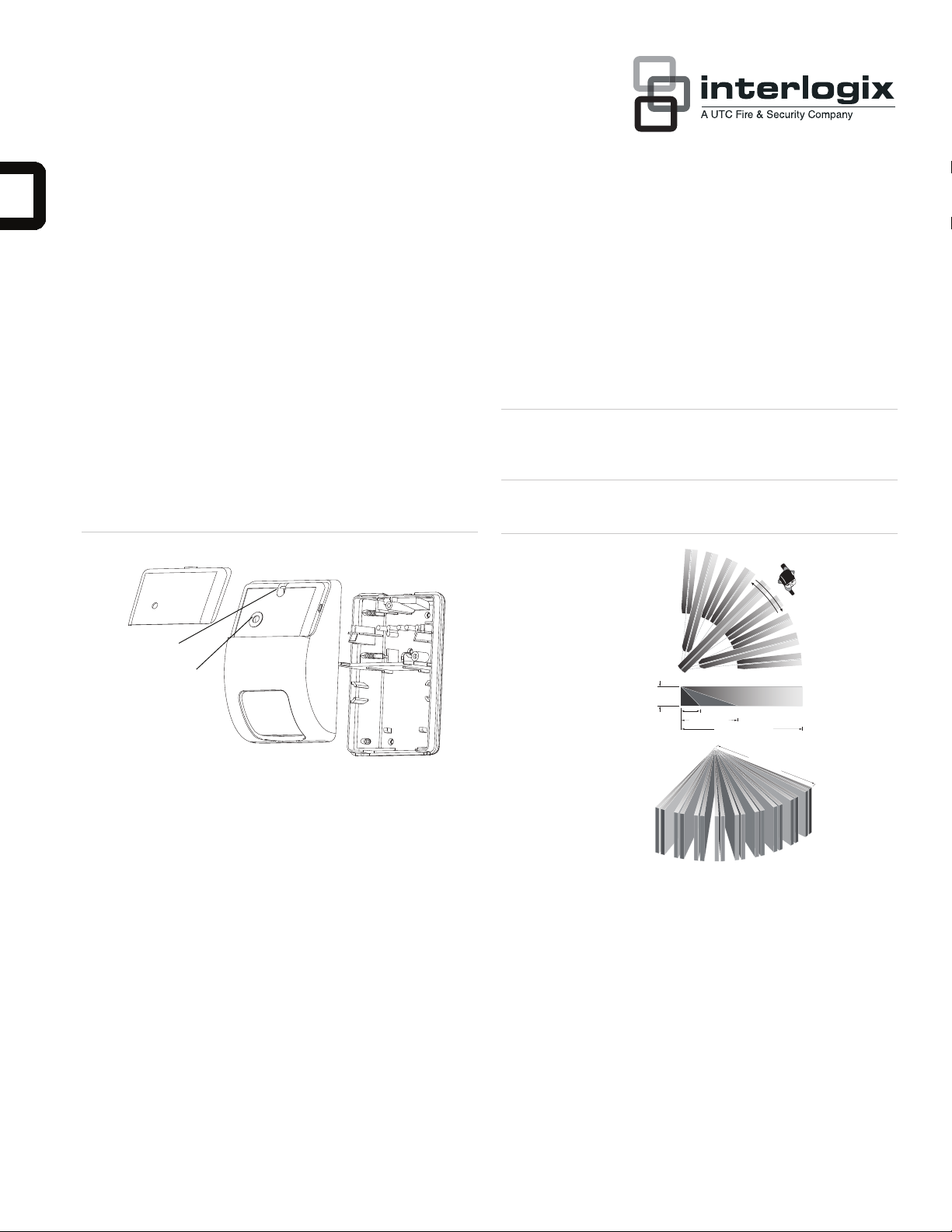
Figure 2: Detection pattern
10.0 ft.(3.0m) maximum
8.0 ft.(2.4m) typical
6.0 ft. (1.8m) minimum
8 ft. (2.4m)
25 ft. (7.6m)
50 ft. (15.2m)
50 ft. (15.2m)
Mounting the sensor
1. To remove the cover plate, insert a flat-bladed screwdriver
between the notch on the top of the cover plate and the
cover. Pry up the cover plate. See Figure 1 above.
Remove the housing screw that holds the cover to the
Selecting a mounting location
2.
base, insert a flat-bladed screwdriver into the slot above
Install the unit so that the expected movement of an intruder
will be across the detection pattern. See Figure 2 below.
the screw hole. Pry the cover off the base. See Figure 1
above.
Avoid possible false alarm sources such as:
P/N 1038277 • REV C • 17MAY11 1
Page 2
3. Pull up on the top edge of the electronics module while
rocking down on the lower edge to remove the module
from the base. Be careful not to touch the pyroelectric
sensor located on the bottom of the module. See Figure 3
below.
Select mounting holes for corner or wall mounting. Use the
4.
base as a template for marking screw hole locations on
the wall. See Figure 3 below.
Strip the cable for 2 inches (5cm) and pull it through the
5.
cable entry hole(s) and strain relief. Make sure that the
cable has slack in the wall. See Figure 3 below.
Use screws and wall anchors, if necessary, to attach the
6.
base to the wall.
7. Select the appropriate coverage pattern. See “Selecting
the covera
ge pattern” below
8. Replace the electronics module by lining up the notches
on the module with the module notch guides and press the
top of the module down until it snaps into the module
guides. See Figure 3 below.
Strip 1/4 inch (0.6cm) of insulation from each wire. Insert
9.
each wire into the appropriate terminal and tighten screws.
See Figure 7 on page 3.
10. Set the sensitivity, range and LED jumpers for the
application desired. See Figure 7 and “Setting the
sensitivit
y, range, and LED” on page 3
Selecting the coverage pattern
The coverage pattern for the unit can be modified to fit specific
applications by masking off mirror curtains. Curtains should be
masked to avoid sources of false alarms, such as heaters, air
conditioners, and windows.
If necessary, use one or more of the following methods to
modify the coverage pattern:
• Use one or both of the plastic masks provided to mask off
large areas of coverage as shown in Figure 4 below.
Mask the appropriate mirror curtains with the adhesive
•
labels provided. See the example shown in Figure 5
below. Do not use shar
p objects to remove unwanted
labels. If necessary, carefully peel the label off.
• Use the cardboard undercrawl window mask to improve
false alarm immunity in the presence of objects within 5
feet (1.5m) and directly under the sensor. See Figure 6 on
e 3.
pag
Figure 4: Plastic masks
21
To replace the cover, insert the closing tabs at the bottom
11.
of the cover into the guides at the bottom of the base and
snap the cover down. Insert the screw. Fit the hole in the
cover plate over the LED and snap the cover plate into
place. See Figure 1 on page 1.
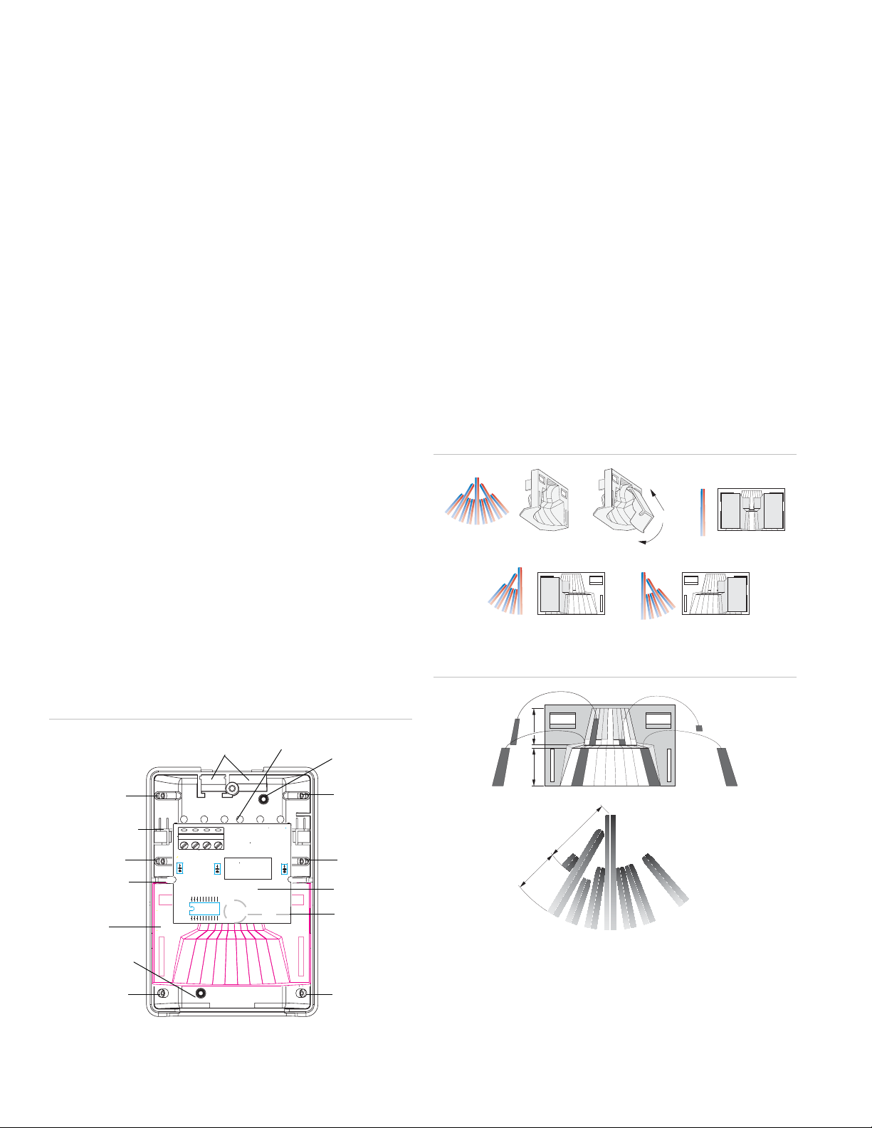
Figure 3: Base
Cable strain
relief
Flat wall mount
knockout
Corner mount
knockout
Corner mount
knockout
Electronics
module
Pyroelectric
sensor
Corner mount
knockout
Corner mount
knockout
Module guide
Corner mount
knockout
Module notch
guide
Mirror
Flat wall mount
knockout
Corner mount
knockout
Cable entry
holes
1
2
Figure 5: Adhesive labels
A
91
2 34567 8
1
8
7
2 3456789
A
6
5
1
2
3
4
B
B
9
2 AP450 Motion Sensors Installation Instructions
Page 3
6: Cardboard undercrawl window mask
A
Figure
7.9 ft.
(2.4m)
5.0 ft.
(1.5m)
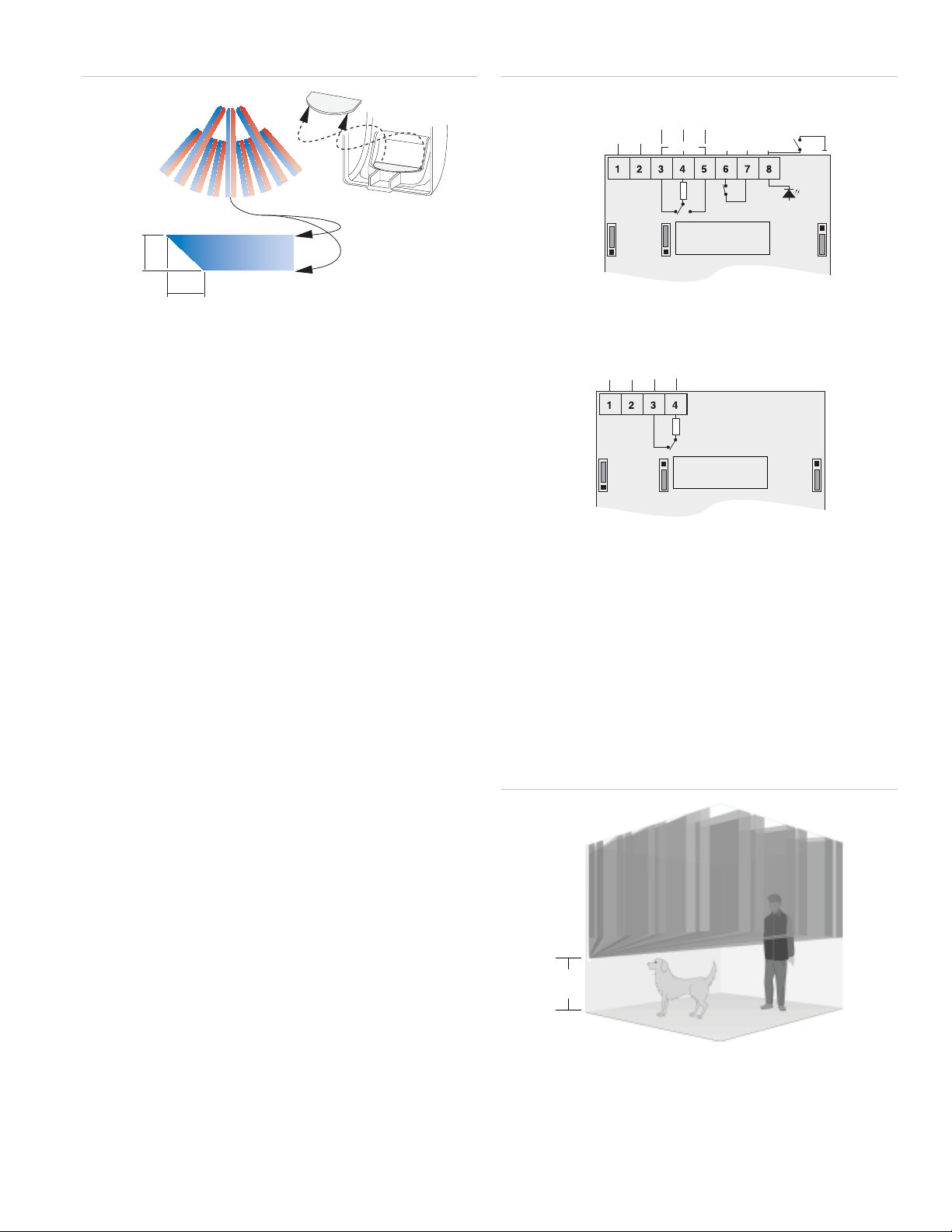
Figure 7: Wiring and jumpers
AP450 (Form C)
NC NOC
0V +12V
J1 J2
50FT
BI
33FT
STD
RANGE
SENS
ALARM
10Ω
TAM PER
LED/
SPARE
OFF/
REMOTE
LED
J3
ON
LED
P450A (Form A)
Setting the sensitivity, range, and LED
The unit provides three jumpers to set sensitivity (J1), range
(J2) and LED (J3). See Figure 7 below.
Sensitivity (J1)
BI = Bi-Curtain Mode (factory default). Increases false alarm
immunity in smaller areas. Requires the intruder to pass
through two curtains to trigger an alarm. Do not use for single
curtain applications or ranges under 5 feet (1.5m).
STD = Standard Sensitivity. Use for most wide-angle or
single curtain applications. Requires the intruder to pass
through only one curtain to trigger an alarm.
Range (J2)
Program J2 for range under 33 feet (10.1m, factory default
for AP450A) or to 50 feet (15.2m, factory default for AP450).
It is important to program the sensor correctly for optimum
sensitivity. Walk test the sensor regularly by walking across the
fields of view and checking that the LED lights and that the
opening relay is indicated back at the control panel.
NC COM
0V +12V
10Ω
J1
SENS
BI
STD
J2
50FT
33FT
RANGE
OFF
J3
ON
LED
Pet alley application
To create a detection-free area close to the floor, mount the
unit 3.5 feet (1.1m) above the floor, upside down (sensor
window towards the ceiling). The cardboard undercrawl
window mask should be in place to reduce exposure to the
ceiling. As shown in Figure 8 below, pets are free to roam
ow the mounting height of the unit without causing an
bel
alarms.
Figure 8: Pet alley
LED (J3)
You can change the LED from enabled (factory default) on
the AP450 sensor (does not apply to the AP450A) to remote
controlled, by moving jumper J3 to the OFF/Remote position.
The LED can then be enabled remotely by applying a 0V
potential to terminal 8.
AP450 Motion Sensors Installation Instructions 3
3.5 ft.
(1.1m)
Page 4

Operation information
The relay contacts will open and the LED will turn on (if
enabled) every time an alarm occurs. The unit should be
allowed to settle for at least one minute after power-up before
walk testing. When walk testing, walk across the curtains, not
directly toward or away from the unit.
Maintaining the sensor
When installed and used properly, the unit provides years of
service with minimum maintenance. To ensure proper
operation, you should walk test the unit annually.
Clean the inside of the unit with a soft bristled brush or
compressed air. Clean the outside with a damp (water) cloth as
needed to keep it free of dust and dirt. Always test the unit
after cleaning.
Figure 9: Dimensions
4.0"
102mm
Dimensions:
Width
Depth
Height
Number of curtains 9
View angle 89°
Detection range 50' (15.2m) max.
2.8" (71mm)
2.0" (51mm)
4.0" (102mm)
Regulatory information
Listings C-UL US
Ordering information
Model # Loop type Electrical
configuration
AP450A Closed Normally
Closed
AP450 Open or Closed Normally
Closed or
Normally Open
(SPDT)
The unit shall be connected to a UL Listed power supply or control unit
capable of providing a minimum of 4 hours standby power. The
equipment shall be installed in accordance with NFPA 70. The unit
shall be tested at least once a year.
Comments
Form A
Form C
w/tamper
2.8"
71mm
2.0"
51mm
Specifications
Input voltage 9 to 15VDC (12V nom.)
Peak to peak ripple 2V max at 12VDC
Current consumption 15mA max.
Mounting height 6' to 10' (1.8m to 3m)
Target speed range 0.7' to 13.0' (0.2m to 4.0m)/sec.
Relay rating w/10
ohms in series
Alarm time 2.5 sec. min.
Tamper switch rating 100mA at 28VDC
Operating temperature 0° to 131° F (-18° to 55° C)
Relative humidity 93% max. non-condensing
Weight 4.25 ounce (120 g)
50mA at 28VDC
Contact information
www.utcfireandsecurity.com or www.interlogix.com
For customer support, see www.interlogix.com/customer-
support
Copyright © 2011 UTC Fire & Security. All rights reserved.
4 AP450 Motion Sensors Installation Instructions
 Loading...