

Interlogix Allegro Installation Manual

8 6 6 0 g 1 0 a .d s f
Contents
,QVWDOODWLRQ,QVWUXFWLRQV
Preliminary 2/5/02
About This Manual ............................................................1
Special Installation Requirements .....................................1
UL Listed Systems .....................................................1
Basic System .........................................................1
Household Burglary Alarm System
Unit (UL 1023) ......................................................1
Household Fire Warning System (UL 985) ...........1
Digital Alarm Communicator System (UL 1635) .1
Central Station Reporting ......................................1
UL-Canada Listed Systems ........................................1
California State Fire Marshall Listed Systems ...........1
Planning the Installation ....................................................1
Standard System .........................................................1
Panel ...................................................................... 1
DTIM .....................................................................1
Additional System Components ............................2
Installing the System .........................................................2
Determine the Panel Location ....................................2
Mounting the Panel ....................................................2
Connecting Detection Devices to Panel Zone Inputs .3
Connecting Intrusion Detection Devices ...............3
Connecting the AC Power Transformer .....................3
Connecting the Backup Battery Pack .........................3
Powering Up the Panel ...............................................4
Programming the Panel .....................................................4
Panel Keypad Button Programming Functions ..........4
Moving Through Program Mode Tiers
and Menus ..................................................................4
Installer Programing Menu Items ...............................4
Entering Installer Programming Mode ..................4
Clearing Memory ....................... ...... ..... ................ 5
Learning the DTIM into the Panel ........................5
Account Menu ....................................................... 5
Account ............................................................5
Phones Menu .........................................................5
Number 1 and 2 ................................................ 5
FMT - CID ....................................................... 6
High Lvl........................................................... 6
Low Lvl............................................................ 6
Openings .......................................................... 6
Closings ............................................................6
Backup ..............................................................6
Dial Dly ............................................................6
Pre-Dial String.................................................. 7
DTMF Dial ..................................................... . 7
Devices ..................................................................7
Add .................................................................. 7
Delete ............................................................... 7
Review ............................................................. 8
Text .................................................................. 8
Downloader ...........................................................9
Number............................................................. 9
DL Code ........................................................... 9
Codes .................................................................... 9
Install Code....................................................... 9
Dealer Code...................................................... 9
Duress Code ..................................................... 9
Apartment Manager ......................................... 9
Timers ..................................................................10
Entry Dly........................................................ 10
Exit Dly .......................................................... 10
Phone Test Frequency..................................... 10
Next Phone Test ............................................. 10
Sleepy Time.................................................... 10
Sleep Hour...................................................... 10
Options ................................................................10
KTP Arm........................................................ 10
Police Panic ................................................... 10
Emergency Panic ........................................... 11
Fire Panic ....................................................... 11
Rcvr Trouble................................................... 11
Panel Tamper ..................................................11
Exit Ext........................................................... 11
Swinger Shutdown ......................................... 11
Quick Arm...................................................... 11
Quick Exit....................................................... 12
Auto Stay Arm................................................ 12
Supv Time....................................................... 12
Alarm Verify................................................... 12
Demo Kit........................................................ 13
Zones ..............................................................13
Reports .................................................................13
AC Fail ........................................................... 13
Low CPU Battery........................................... 13
Phone Test ...................................................... 13
Auto Phone Test ............................................. 14
Siren .....................................................................14
Siren Time Out ...............................................14
Trouble Beeps................................................. 14
Alarm Volume ................................................14
Exit - DL ..............................................................14
User Programing Menu Items ...................................14
Entering User Programming Mode .....................14
Document Number: 466-1821 Rev. A PRELIMINARY
February 2002
$OOHJUR
ITI Part No. 60-874-95

Preliminary 2/5/02
Codes................................................................... 14
Apartment Manager ....................................... 14
Primary .......................................................... 15
User 2, 3, 4..................................................... 15
Time .................................................................... 15
Phone Test ........................................................... 15
Sensor Test .......................................................... 15
Volume ................................................................ 16
Exiting User Programming Mode .......................16
Downloader Programming .......................................16
ToolBox Downloader Programming ...................16
Testing the System ...........................................................16
Basic System Commands .........................................16
Testing Sensors/Zones ..............................................17
If a Wireless Sensor Does Not Test .....................17
Testing Phone Communication .................................17
Testing Central Station Communication ..................17
Appendix A: Troubleshooting .........................................18
Appendix B: Reference Tables ........................................22
Appendix C: Installation Menus.......................................28
Specifications....................................................................29

Preliminary 2/5/02
FCC Notices
FCC Part 15 Information t o the U ser
Changes or modifications not expressly approved by Interlogix Inc. can void the user’s authority to operate the equipment.
FCC Part 15 Class B
This equipment has bee n te ste d and found to comply with the limits for a Clas s B digi tal device, pursuant to part 15 of the FCC Rules. These limits are
designed to provide reason able protection against interference in a resid en ti al installation.
This equipment generates, uses, and can radiate radio frequency energy and, if not installed and used in accordance wit h th e instructions, may cause harmful
interference to radio communications. However, there is no guarantee that interference will not occur in a particular installation.
If this equipment does cause ha rm ful interference to radio or television reception, which can be determined by turning the equipm ent off and on, the user is
encouraged to try to correct the interference by one or more of the followin g measures:
❑ Reorient or relocate the receiving antenna.
❑ Increase the separation between the equipment an d receiver.
❑ Connect the af f e cted equipment and the panel receiver to separate outlets , on different b ranch circuits.
❑ Consult the dealer or an experienced radio/TV technician for help.
FCC ID: B42-785B-ALGR O
2266 Second Street North | North Saint Paul Mn | 55109 | 800-777-2624 | www.interlogixinc.com
©2001 Interlogix,™ Inc. Interlogix is a tr ademark of Interlogix, Inc. IT I is a registered tradema rk of Interlogix, Inc.

2
Allegro
Preliminary 2/5/02
About This Manual
This manual provides information for planning, installing,
programming, and testing this security system. When necessary, this manual refers you to other documentation
included with compatible devices.
Planning sheets are included for you to record hardware
layout and software programming settings.
Special Installation Requir ements
This security system can be used as an intrusion alarm system, a fire alarm system, and an emergency notification
system.
Some installations may require configurations dictated by
city/state codes, insurance, or Underwriter’s Laboratories
(UL). This section describes the various component and
configuration listings.
UL Listed Systems
This section describes the requirements for UL Listed
systems.
Basic System
Control Panel (60-874-95R).
Standard Class II 8.0 VAC, 300 mA Power Trans-
former; manufacturer—Sino America, (A1014444-0)
ITI Part No. 22-117.
Dialog Telephone Interface Module (DTIM)
(60-879-95R).
Backup Battery 4.8 VDC rechargable NiCd battery
pack (34-057).
Household Burglary Alarm System Unit (UL 1023)
Basic system, plus:
Hardwire Magnetic Contact (13-068 or 13-071) or
Wireless Learn Mode Door/Window Sensor (60-362),
Wireless Learn Mode PIR Motion Sensor (60-703-95
or 60-639).
RECEIVER TROUBLE set to on.
EXIT DELAY set to 60 seconds or less.
QUICK EXIT set to off.
SIREN TIMEOUT set to 4 minutes or more.
ENTRY DELAY set to 45 seconds or less.
SLEEPY TIME set to off.
Household Fire Warning System (UL 985)
Basic system, plus:
Wireless Smoke Sensor (60-506-319.5 or 60-848-95)
learned in to sensor group 26.
RECEIVER TROUBLE set to on.
SLEEPY TIME set to off.
EXIT EXTENSION set to off.
Digital Alarm Communicator System (UL 1635)
Basic system, plus:
AC FAILURE set to on.
LOW CPU BATTERY set to on.
AUTO PHONE TEST set to on.
PHONE TEST FREQUENCY set to one.
NEXT PHONE TEST set to one.
Central Station Reporting
The panel has been tested with the following central station
receivers using SIA and Contact ID reporting formats:
ITI CS-5000 Central Station Receiver.
Sur-Gard Central Station Receiver with models
SG-DRL2A and SG-CPM2.
UL-Canada Listed Systems
This section describes the requirements for ULC (UL
Canada) Listed systems.
CSA Certified Accessories
Residential Burglary Alarm System Unit (ULC-S309)
Same as “UL Basic System and Household Burglary Alarm
System Unit (UL 1023).”
California State Fire Marshall Listed
Systems
Same as Household Fire Warning System (UL 985).
Planning the Installation
This section describes the systems’s capabilities to help you
get familiar with the system. Appendix B provides planning
sheets with tables that let you record the hardware and programming configuration of the system to help prepare for
system installation.
Standard System
Panel
The panel keypad provides complete system programming
and operation control. Displays system messa ges and indicates system status.
DTIM
The DTIM allows the panel to communicate with the central monitoring station.
Note
The DTIM does not have a backup battery.
The following describes the system’s basic (out-of-box)
hardware capabilities.
Power: AC Class II, 8 VAC transformer.
Backup Battery 4.8 VDC rechargable NiCd battery
pack. (34-057)
One Supervised Hardwire Zone: I nput for v ariou s hard-

3
Allegro
Preliminary 2/5/02
wired detectors.
Built-In Radio Receiver: Allows use of up to 20 ITI
319.5 MHz. crystal and/or SAW Learn Mode wireless
sensors and touchpads.
Built-In Siren: Capable of 85 dBa @ 3m.
Built-In Panel Keypad.
Liquid Crystal Display (LCD).
Additional System Components
The system can monitor up to 20 sensors using any combination of the following sensors:
Door/W indow Sen so r (60-6 70-95R).
2-Button Keychain Touchpad (60-607-319.5).
Remote Handheld Touchpad (60-671-95R).
Indoor Motion Sensor (60-639-95R).
Carbon Monoxide Alarm (60-652-95)
*
.
Smoke Sensor (60-747-95).
ShatterPro Glass Break (60-873-95)*.
Other supported ITI 319.5 Sensors (excluding other
touchpads).
Note
Both ITI SAW and Crystal sensors function with this control
panel.
Installing the System
Before starting the installation, plan your system layout
and programming using the worksheets provided in Appendix B.
Installing the system consists of the following:
Determining the Panel Location.
Mounting the Panel.
Identifying Main Panel Components.
Connecting Detection Devices to Panel Zone Input.
Installing an RJ-31X Phone Jack for the DTIM.
Connecting the AC Power Transformer.
Powering Up the Panel.
Determine the Panel Location
Before permanently mounting the panel, determine panel
location using the following guidelines:
Avoid running wires parallel with electrical wiring or
fixtures such as fluorescent lighting, to prevent wire
runs from picking up electrical noise.
Mount the panel at a comfortable working height
(about 45 to 55 inches from the floor to the bottom of
the panel).
Leave space above the panel for optional antenna plas-
tic (min 4 inches).
Important !
The panel must be mounted at least 10 feet from any DTIM
or between any two DTIMs.
Mounting the Panel
Use the following procedure to mount the panel to the wall
or wall studs.
CAUTION
Make sure you are free of st at ic elect r ic i ty whenever you
work on the panel with the back mounting plate removed.
Using an approved grou nding strap is recommended.
To mount the panel:
1. Remove the panel from the back
mounting plate by lifting the tab
located on the top and pulling
back.
Figure 1. Remove back
by lifting tab
2. Remove the wiring knockout.
Figure 2. Back Mounting Plate
3. Feed all device wires through the knockout and place
the back mounting plate in position against the wall.
4. Level the back mounting plate and mark the top and
bottom mounting holes.
5. Install anchors where studs are not present.
6. Partially insert a screw into the top mounting hole location then hang the back mounting plate on the screw.
7. Recheck for level, insert the lower screw, and tighten
both mounting screws.
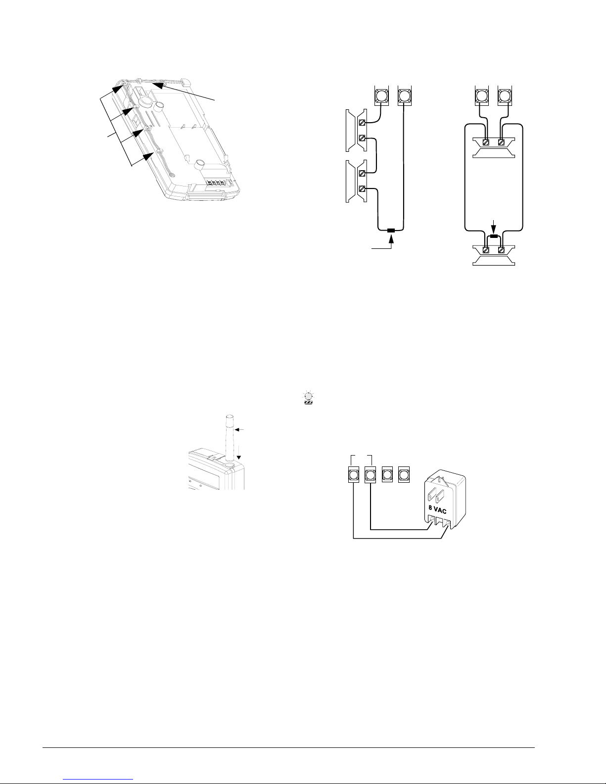
8. Install the antenna. There are three antenna options to
choose from:
*) Not investigated by UL.
Tab
Antenna
(Option 3)
Antenna
Wire Hole
(Option 2)
Wire
Clip
Mounting
Holes
Knockout
Tamper
Switch
4
Allegro
Preliminary 2/5/02
Figure 3. Antenna wiring as shipped
Option 2: Hang antenna in wall (longest range).
➢ When you mark the back mounting plate’s two
mounting holes, also mark where the antenna
hole is (see Figure 2 for antenna wire hole lo cation).
➢ Where the antenna hole was marked, drill a
hole into the wall.
➢ Remove the antenna loop (see Figure 3) from
the panel cabinet clips and feed through the
antenna hole and down into the wall.
Option 3: Optional antenna housing (included in
accessory pack) and attach it to the panel (medium
range).
➢ Push the antenna housing down into the top-
right hole of the panel until it snaps into place
(see Figure 4).
➢ Remove the antenna
loop from the last clip
on the panel cabinet
and insert it into the
antenna housing.
9. Place panel cabinet into back
mounting plate and snap into
place.
Figure 4. Optional Antenna
Housing
Connecting Detection Devices to Panel
Zone Inputs
Zone input is supervised us ing a 2k-ohm, end-of- line (EOL)
resistor (included with panel) at the last device on the circuit. It accepts either normally open (N/O) or normally
closed (N/C) detection devices.
The maximum loop resistance for each zone input is 300
ohms, plus the 2k EOL resistor.
Connecting Intrusion Detection Devices
Figure 5 shows the typical wiring for N/C and N/O door/
window intrusion detection.
Figure 5. Wiring N/O or N/C Intrusion Detection devices
Connecting the AC Power Transformer
(22-117)
The panel must be powered by a plug-in stepdown transformer that supplies 8 VAC, 300 mA.
Connect the power transformer to the panel as shown in
Figure 6.
CAUTION
Do not plug in the power transformer at this time. The panel
must be powered up using the sequence of steps described
in the “Powering Up the Panel ” sec tion
Figure 6. Connecting a Power Transformer
Connecting the Backup Battery Pack
The panel will receive its primary power from an AC class
II transformer. In the event of an AC power failure, the
panel will be powered by a battery pack containing four
rechargeable NiCd batteries.
Clips
Antenna
Loop
Antenna
Housing
Push Down
Into Panel
6
3 43 4
Panel Terminals
Normally
Closed
(N/C)
Contacts
In Series
Normally
Open
(N/O)
Contacts
In Parallel
2k Ohm
EOL Resistor
49-454
2k Ohm
EOL Resistor
49-454
Or
3
4
1
2
Z
C
O
M
Z
O
N
E
AC
5
Allegro
Preliminary 2/5/02
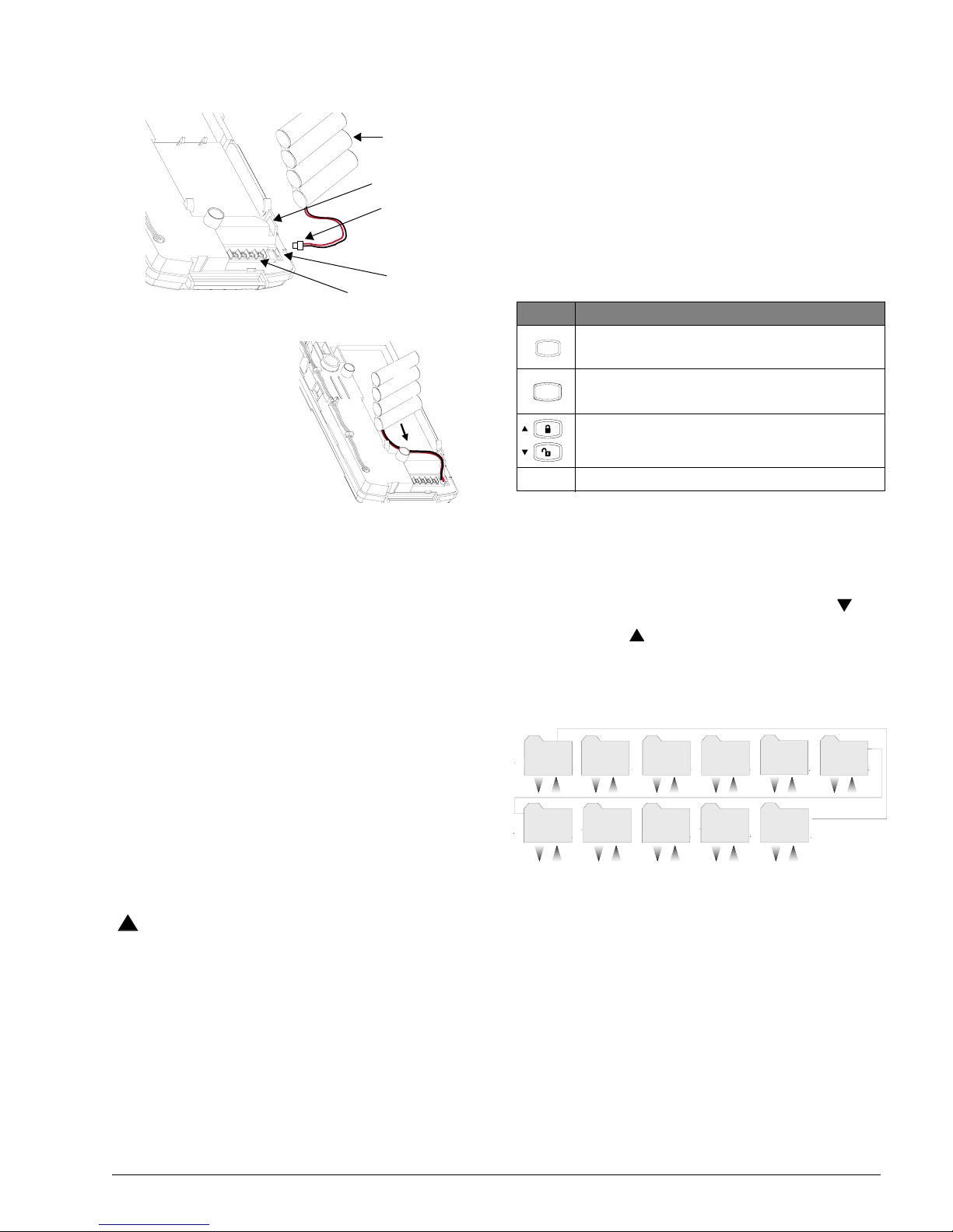
To connect the backup battery pack:
Figure 7. Connecting the Battery Pack
1. Remove the panel housing from the back
mounting plate by lifting the tab located on
the top of the panel and
pulling bac k.
2. Slide the battery pack
into the space provided
on the back of the panel
(Figure 8).
Figure 8.Placement of Batt ery
3. Plug the battery pack lead i nto t he slot pr ovide d next to
the wire terminals (Figure 7).
Note
Be sure to run the battery pack wires below the battery and
thru the wire channel.
4. Replace the panel housing into back mounting plate
and snap into place.
Note
See Appendix A: Troubleshooting on page 19 if the panel
displays
LOW BATTERY.
Powering Up the Panel
After connecting and wiring all devices to the panel, you are
ready to apply AC power to the panel.
To power up the panel:
Plug the transformer into an outlet that is not controlled
by a switch or ground fault circuit interrupt (GFCI). Be
sure to screw the top of the transformer onto the outlet
so that doesn’t fall out of the outlet.
The message,
PANEL POWERED UP, will be displayed
WARNING
!
Be careful when securing the transformer to an outlet with
a metal cover. Hold the cover tightly in place. You could
receive a serious shock if the metal outlet cover drops
down onto the prongs of the plug while you are securing
the transformer and cover to the outlet box.
Note
If the panel does not display any th in g, imm ediately unplug
the transformer and disconnect the backup battery. Refer
to the “Troubleshooting” (on page 19) section.
Programming the Panel
This section describes how to program all settings found in
programming mode. You can program the panel manually
using the panel keypad to program on site. Or, using the
T oolBox software, you can automatically program remotely
via a modem and phone line.
Panel Keypad Button Programming
Functions
In program mode, panel keypad buttons let you navigate to
all installer programming menus for configuring the system.
Table 1 describes the panel keypad button functions in program mode.
Moving Through Program Mode Tiers
and Menus
There are three tiers of programming menus. Tier 1 menus
are accessible immediately after entering program mode.
In Figure 9 arrows pointing right represent pressing
to
advance forward through the menus. Arrows pointing left
represent pressing
to move through the menus in reverse.
The arrows below the tier 1 menu represents pressing
ƒ
and ‚ buttons.
Figure 9. Tier 1 Programming Menus
To advance to tier 2 program menus press the up or down
arrow keys to scroll thru the tier 1 menus. When you find
the menu you want to make changes to press
ƒ once. This
will take you to tier 2 program menus.
Installer Programing Menu Items
This section guides you through the installer programing
menu items as they appear in sequence with the exception
of clearing memory.
Entering Installer Programming Mode
Entering programming mo de on s ite is d one from the pa nel,
using an installer code. The default installer code is
8 6 6 0g4 6 a .d s f
Battery Pack
Battery Pack
Battery Pack
Location
Battery Slot
Wire Terminals
Lead
Wire Channel
Table 1: Button Functions
Button Programming Function
Selects menu item or data entry. Toggles between
on and off whenever needed.
Deselects menu item or data entry (if pressed
before #).
Scroll through available options at the current
menu tier.
0 thru 9 Enter numeric values wherever needed.
#
B y p a s s
S e l e c t
B a c k
*
S t a t u s
T i m e r sP h o n e s
D e v i c e s D o w n l o a d e r
C o d e s
A c c o u n t
#
*
#
*
#
*
#
*
#
*
#
*
C l e a r
M e m o r y
E x i t - D L
R e p o r t s
S i r e nO p t i o n s
#
*
#
*
#
*
#
*
#
*
T i e r 1 M e n u
6
Allegro
Preliminary 2/5/02
4321. The system can be put into program mode only
when the system is disarmed.
To enter programming mode:
With the system disarmed, press 8 + CODE.
To clear memory:
It is strongly recommended that you clear memory on all
newly installed panels before programming.
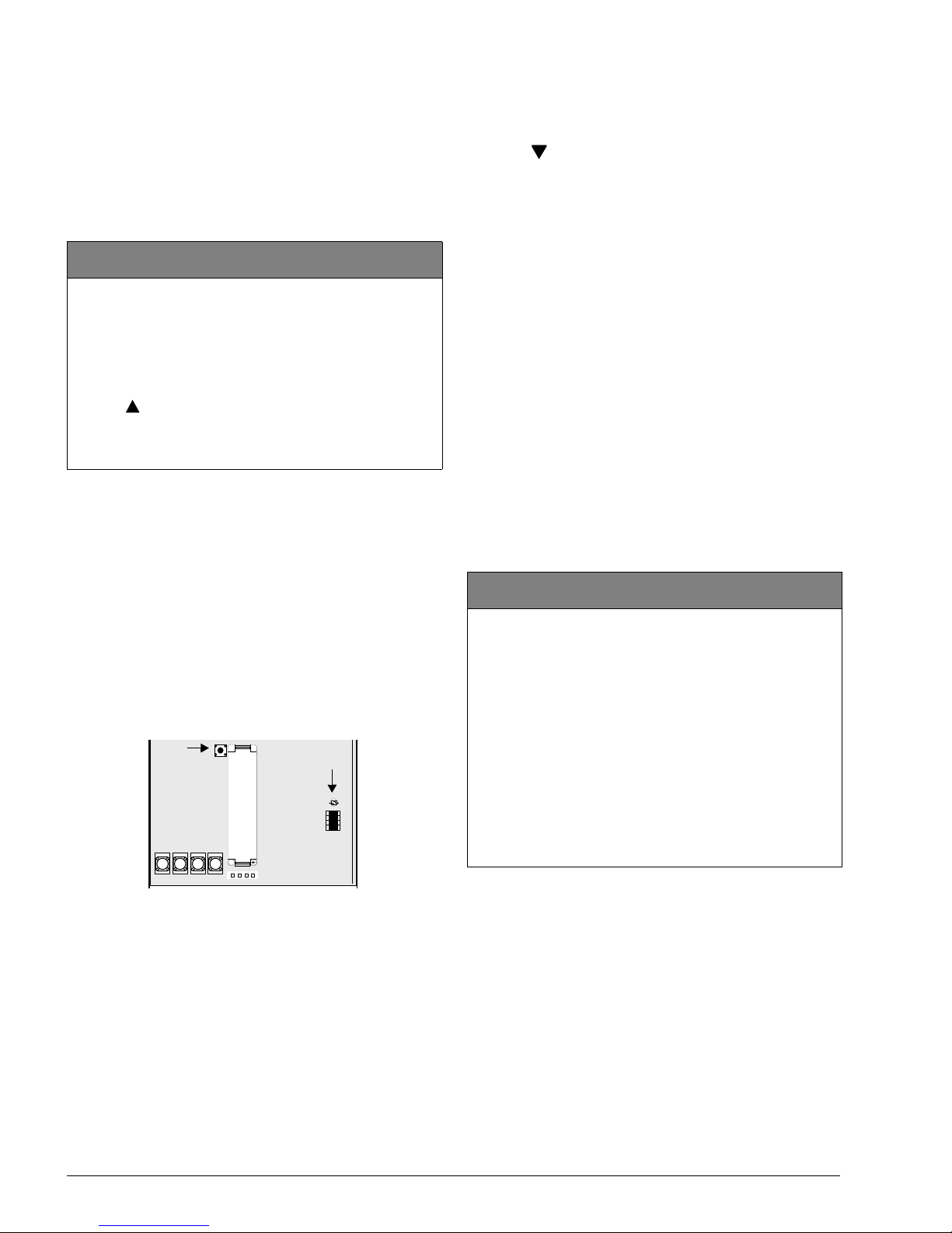
Learning the DTIM into the Panel
The module learns in using the 3-2-1 procedure similar to
the encrypted key fob. There is no time limit between learn
in attempts. The LED will blink when the correct number of
tamper switch presses have been entered. Be sure to wait for
the LED to turn off after each flash. The tamper switch
sequence of 3-2-1 mus t be mirro red by the LED fo r th e user
to continue.
Important !
Do not wait more than 1-2 sec onds between steps 5 and 6
or steps 6 and 7 after releasing th e tam per switch. If you
wait too long between these steps, the LED will not flash
and you will have to start over.
Figure 10. DTIM Tamper Switch and LED Locations
To learn the DTIM into the panel:
1. Remove the DTIM cover.
2. Press twice and # once. The display shows
PHONES;
DEVICES; ADD.
3. Press #. The display shows ZONE 01 - TRIP.
Note
The DTIM is normally learned into zone 01, Phone Module.
4. Press the DTIM’s tamper switch three times, holding
the tamper switch down on the third press and wait for
the LED to flash three times. Release the tamper switch
after the third flash.
5. Press the DTIM tamper switch twice, holding the
tamper switch down on the second press and wait for
the LED to flash two times. Release the tamper switch
after the second flash.
6. Press and hold the tamper switch down until the LED
flashes once. The panel beeps once indicating the
DTIM was learned into the panel.
Once the DTIM has been learned into the panel, proceed to
programming the rest of the panel.
Account Menu (1st Tier)
The account menu lets you set up the account number used
for customer identification for the central monitoring station.
Clearing Memory (Clear Memory)
1st Tier
(Default = none) Clear memory deletes all existing
programming information and then resets the panel settings to
their default settings. The dealer code is not erased when panel
memory is cleared.
To clear panel memory:
1. Press 8, and enter the dealer or installer code. The display
shows
ACCOUNT.
2. Press twice. The display shows EXIT - DL; CLEAR MEMORY.
3. Press #.
4. Enter code to clear memory . After a few seconds the system
restarts and the message
PANEL POWERED UP is displayed.
L O C A L
R I N G
R I N G
T I P L O C A L
T I P
+
Tamper
Switch
LED
Account
1st Tier
(Default = 00000, Parameters = 4-10 digits; 0-9, A-F) The
account number is used as panel (or customer) identification
for the central monitoring station. The panel sends the account
number every time it reports to the central station. Account
numbers must be 4 to 10 characters long.
Alpha characters A–F can be assigned to the account number
by pressing and holding buttons 1–6 respectively, until the
character appears.
Note
The CID format only supports account numbers with letters B through F, or numbers 0 through 9 (or a combination
of those letters and num ber s) .
To program an account number:
❑ Press #, then enter the 4-10 digit code (0-9 and A-F) and
press #.

7
Allegro
Preliminary 2/5/02
Phones Menu (1st Tier)
The phone menu lets you set up cen tral st ation reporti ng for
the system.
Number 1 an d 2 (Phones—Phone 1 and Phone 2)
3rd Tier
(Default = none, Parameters = 24 digits; 0-9, *, #) This setting
is used for programming the central station receiver phone
number. Phone number s can be 1 to 24 digits long, including
pauses or * and # characters.
To enter pauses, press the silent key. A pause is displayed as P.
To enter *, press and hold the 7 key until * appears. A star (*)
is displayed as *.
To enter #, press and hold the 9 key until + appears. A pound
(#) is displayed as +.
Note
The phone numbers are not accessible if a Dealer Code is
programmed and the Ins taller Code is used to enter
installer programming m ode. To access these nu m bers
when a Dealer Code is pro grammed, you must enter
installer programming mode using the Dealer Code.
Note
Call-waiting services should be disabled to prevent interrupting panel communication to the central monitoring station. To program a dialing prefix that di sables call-waiting,
see Pre-Dial String on page 8.
To program number 1/2:
❑ Enter 1-24 digit number and press #.
FMT - CID (Phones—Phone 1 and Phone 2)
3rd Tier
(Default = CID) This setting determines whether the panel
uses the SIA (off) or CID (on) reporting form at for central
station communication.
To select reporting format under phone 1/2:
Press # to select on or off.
High Lvl (Phones—Phone 1 and Phone 2)
3rd Tier
(Default = Phone 1: on, Phone 2: off) When High Level
Reporting is on, the following conditions report to the central
station:
❑ Fire, Police, Emergency, and Duress alarms
❑ Phone Test
❑ Receiver Trouble
❑ Entering or Exiting Sensor Test Mode
❑ Tamper Conditions, including Zone Tampers and System
Tamper (40 incorrect key presses)
❑ No Activity
See Table B4: “Central Station Reports,” on page 27 for a
complete list of reports.
Note
For UL listed installations, High and Low- level report s mus t
be set to on.
To turn high-level reports on or off under phon e 1/2:
Press # to turn it on or off.
Low Lvl (Phones—Phone 1 and Phone 2)
3rd Tier
(Default = Phone 1: on, Phone 2: off) When this setting is on,
the following non-alarm conditions report to the central
station:
❑ Forced Arming
❑ Hardwire Zone Trouble
❑ RF Supervisory
❑ RF Low Battery
❑ Phone Test
See Table B4: “Central Station Reports,” on page 27 for a
complete list of reports.
To turn low-level reports on or off under phone 1/2:
Press # to turn it on or off.
Openings (Phones—Phone 1 and Phone 2)
3rd Tier
(Default = off) This setting determines whether an opening
report is sent to the central station. When turned on, the panel
sends an opening report when the system is disarmed.
To turn opening reports on or off under phone 1/2:
Press # to turn it on or off.
Closings (Phones—Phone 1 and Phone 2)
3rd Tier
(Default = off) This setting determines whether a closing
report is sent to the central station. When turned on, the panel
sends a closing report when the system is armed.
To turn closing reports on or off under phone 1/2:
Press # to turn it on or off.
Backup (Phones—Phone 2)
3rd Tier
(Default = on) This setting determines whether the DTIM uses
phone number 2 for reporting if three initial attempts on phone
number 1 are unsuccessful. PHONE 1 is backed up by PHONE 2.
The DTIM makes up to 16 attempts (8 per phone number),
alternating between the two programmed phone numbers.
For example, if Backup is on and three failed reporting
attempts occur using
PHONE 1, (panel displays PHONE 1 FAIL), the
DTIM switches to PHONE 2 for three more reporting attempts.
If these attempts fail, (panel displays PHONE 2 FAIL), the DTIM
switches back to PHONE 1 for f ive mo re r epor tin g att emp ts and,
if necessary, switches back to
PHONE 2 for five final attempts.
If these final attempts fail, the panel will display PHONE FAILURE.
To turn backup on or off:
Press # to turn it on or off.
8
Allegro
Preliminary 2/5/02
Devices (1st Tier)
(Default = none) Devices include a HW sensor, RF sensors,
RF touchpads, and other RF devices such as the DTIM.
Dial Dly (Phones)
2nd Tier
(Default = 30 seconds, Parameters = 15-120 seconds) Dial
Delay determines how much time the user has to stop a panel
before it sends a false alarm to the central station.
Alarm reports from sensors in groups 00–03, 10, and 13-20
can be aborted. To abort the dialing attempt, the user must
disarm the system within the Dial Dly time setting. Cancel and
restoral re ports from these sensor groups are aborted at the
same time. The following reports can also be aborted.
❑ System Tamper Alarm/Cancel.
❑ Touchpad Police and Emergency Pani c /Ca n c e l .
❑ Forced Arming
❑ Recent Closing and Two Trip Error.
Note
Fire alarm reports to the central station cannot be aborted.
To set the dial dly:
Enter the desired amount of time ( 15-120 second s) and
then press #.
Pre-Dial String (Phones)
2nd Tier
(Default = none, Parameters = 8 digits; 0-9, *, #, pause) This
feature lets you set up a dialing prefix to disable the call
waiting feature before the panel makes its first dialing attempt
to any programmed central monitoring station or downloader
phone number. The prefix can be up to eight digits. Contact
your local phone company for call waiting disable numbers
and characters. See Number 1 and 2 programming on page 7
for informati on on how to program * and # cha r a cters.
Note
The pre-dial string is not accessible if a Dealer Code is programmed and the Installer C ode is used to enter installer
programming mode. To access the pre-dial string option
when a Dealer Code is programmed, you must enter
installer programming mode using the Dealer Code.
To set the pre-dial string:
Enter the desired numbers and then press #.
DTMF Dial (Phones)
2nd Tier
(Default = on) This setting determines whether the panel uses
DTMF tones (on) or pu lse (o f f) f or di ali ng p rogr amm ed ph one
numbers.
To turn DTMF dialing on or off:
Press # to turn it on or off.
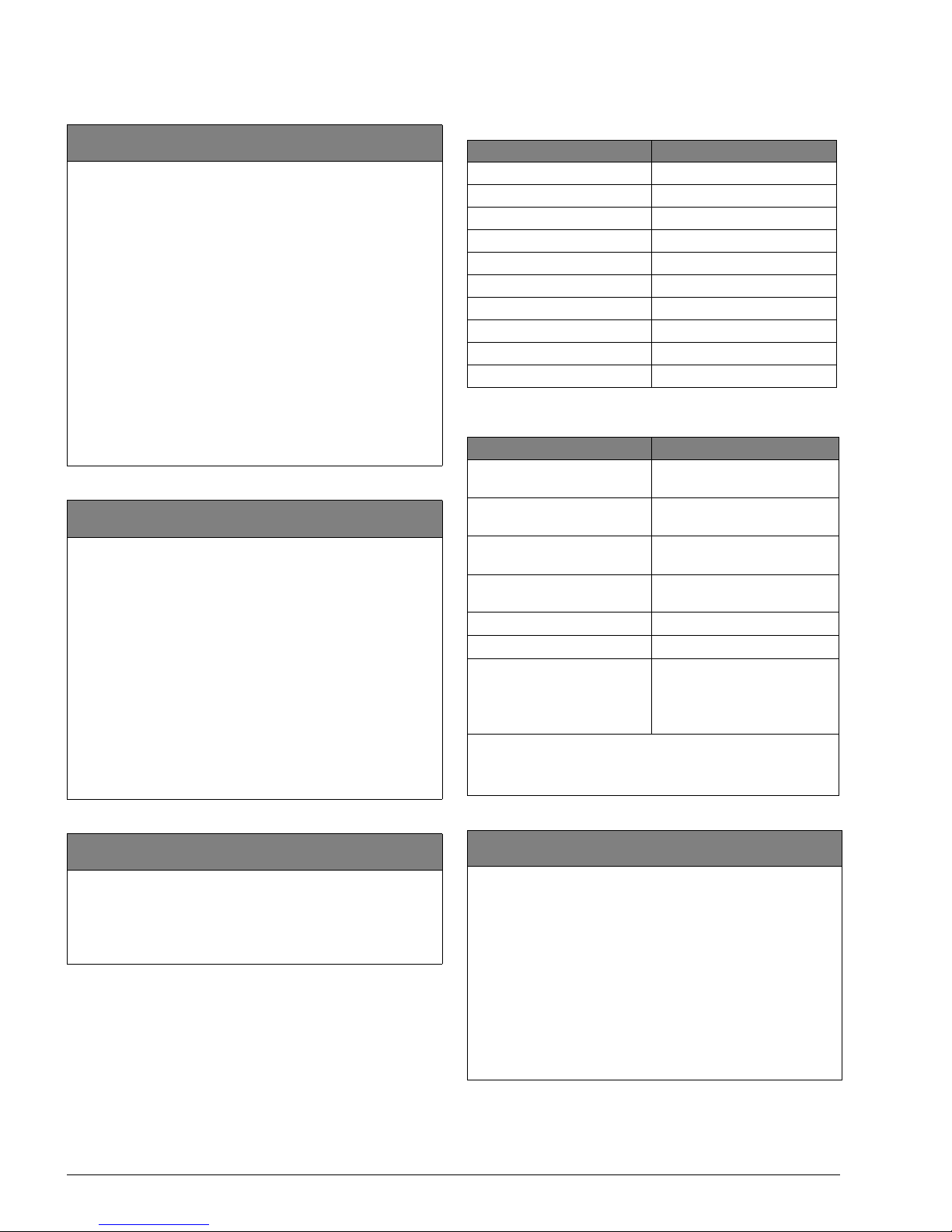
Table 2: Sensor Group Assigned to Device
Device Sensor Group
Keyfob or RF Touchpad 1
Portable Panic 1
HW Input 10
DWS 10
PIR 17
Sound 17
Glassguard 17
Smoke 26
Rate of Rise 26
DTIM 36
T a ble 3: Device Programming
Device To Program
Door/Window Sensor (SAW) Press button on top of sensor
(cover removed).
Motion Sensor Press button on back of sensor
(mounting plate removed).
Keychain Touchpad
(non encrypted)
Press lock & unlock buttons
until LED blinks.
Keychain Touchpad
(encrypted)
See Note.
Crystal Sensors See Note.
DTIM 3-2-1 sequence (on page 6).
Hardwire Sensor For normal ly c l osed - separate
sensor from magnet.
For normally opened - close
sensor then reopen.
Note
When installing crystal sensor s and encrypted keychain
touchpads, use the installat i on i nst r uctions included in
their packing boxes.
Add (Devices)
2nd Tier
(Default = none) When adding devices, the panel will
automatically assig n the device to a sensor gr oup based on the
type of device. Table 2 outlines the sensor group assigned to
each device.
Note
To override the preassigned sensor number, use the arrow
keys to skip to the desir ed sensor number.
To add a device:
1. Press #. The display shows ZONE {01- 20} - TRIP.
2. Trip the sensor (see T able 3). The panel beeps twice to indicate the sensor was successfully learned into the panel.
3. Repeat step 2 until all desired zones are added.
 Loading...