

Interlogix AdvisorOne Panel Quick Installation Manual
`
EN
CNF
ES
PR
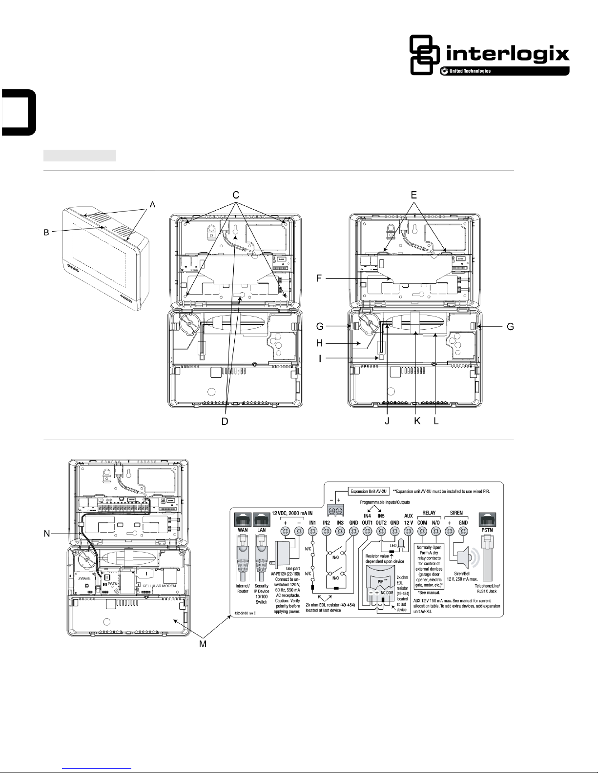
Figure 1. Panel
Figure 2. Panel Mounting Holes
Figure 3. Panel With Covers
Figure 4. Panel Connections
AdvisorOne Panel Quick Installation Guide
P/N 466-4403 Rev M 16SEP2015 1 / 18
.

English: Installation Sheet
System Overview
The Advisor™One self-contained lifestyle management and security system detects situations and provides control and information to
homeowners (P/N AVO-1037). The system can support up to 100 wireless sensors (a maximum of 40 of which may be a combination
of Smoke and/or CO detectors), 250 user codes, and 250 key fobs.
To support normal system operation, the AdvisorOne panel must be connected to the Internet over a Broadband connection (either
wired or Wi-Fi).
The AdvisorOne system may be configured from the factory to incorporate BlueTooth, Wi-Fi, and Z-Wave technologies. If present,
BlueTooth is used to provide mobile device access and control. Wi-Fi is used to provide wireless Ethernet connections to a router
and/or provide wireless Ethernet connection to additional Interlogix touch screens and IP cameras. Z-Wave is used to control lights,
thermostats, door locks, and other appliances.
This guide is a reference for basic installations. Installation should be performed by trained technicians. The system should be serviced
annually or as needed. Additional information is contained at www.interlogix.com/Advisor. For customer support, see
www.interlogix.com/customer-support or call + 1 855 286 8889.
Installation
The AdvisorOne panel is intended for indoor use only.
Getting Started
1. Do not remove film cover from the touch screen until installation is complete.
2. Lay the panel on a flat surface with the touch screen facing up.
3. Open the panel by pressing down on the tabs (A in Figure 1) and carefully swing open the panel chassis.
CAUTION: Use static electricity precautions when handling electronic components.
Mounting
1. Choose a panel location where power can be provided, alarm sounds can be heard, and the panel is easily accessible for
operation.
Ensure that the site is optimum for all intended wireless communication capabilities.
Note: When choosing the AC outlet location for the external DC power supply, make sure the outlet is not controlled by a switch
and is not part of a ground fault circuit interrupt (GFCI).
2 Remove the Terminal Cover (F in Figure 3) by pressing the tabs down (E in Figure 3) and rotating the cover upward.
Note: Removing the Terminal Cover is required to gain access to the terminal strip.
3. Run all necessary power, phone, siren, data, and hardwired contact wires to the desired panel location.
Before drilling holes to mount the panel, be aware of any electrical wiring at the drilling location.
4. Hold the back plate against the wall and mark the two primary mounting hole locations (D in Figure 2) with a pencil.
5. Drill the two primary mounting holes.
If no studs are present, insert drywall anchors (provided).
6. Secure the two mounting screws (provided) to the two primary mounting locations on the wall marked in step 4.
Do not tighten the screws at this time. Leave enough clearance to mount the back plate.
7. Mount the panel to the wall.
Be sure the panel chassis is supported when being opened. If not supported, the chassis could contact the wall and damage the
touch screen.
8. Level the panel and secure the two primary mounting screws.
Note: In addition to the two primary mounting holes, four optional mounting holes (C in Figure 2) can be used if needed.
2 / 18 AdvisorOne Panel Quick Installation Guide

Device
Device Current Draw
Wire Requirements
Hardwired Interior Siren (13-949)
Standby 0 mA
Alarm 85 mA
22 AWG: 750 ft. maximum
18 AWG: 1,500 ft. maximum
Piezo Dynamic Exterior Siren (13-950)
Standby 0 mA
Alarm 150 mA
22 AWG: 750 ft. maximum
18 AWG: 1,500 ft. maximum
12 VDC 2A Power Supply
22 AWG: 8 ft. maximum
18 AWG: 25 ft. maximum
Telephone (RJ-31X)
4-conductor 26 AWG or larger
Wired Input
22 AWG: stranded: 200 ft. maximum
18 AWG: stranded: 500 ft. maximum
Wired Output
50 mA
18 AWG: stranded
Wiring and Connections
Note: Follow standard wiring practices.
The AdvisorOne panel has 16 screw terminals (see M, wiring diagram in Figure 4) and WAN, LAN, and PSTN connectors. The WAN
port is used to connect to IP Ethernet. The LAN port is used to learn or connect IP devices.
Wiring Requirements
The total system wire length allowed can vary depending on devices powered by the panel, the wire length between devices and the
panel, and the combined wire length of all devices. For maximum wire length allowed between compatible devices and the panel, see
Table1.
Table 1: Device Current Draw and Wiring Requirements
Wiring External Contacts
The AdvisorOne panel has five inputs labeled IN1 - IN5 (see M, wiring diagram in Figure 4) that are used for connecting devices to the
panel. IN1 - IN3 are dedicated inputs. IN4/OUT1 and IN5/OUT2 can be configured as either inputs or outputs, depending on system
programming configuration. Advisor One does not supply power for sensors. Sensor Zones must be of the normally open or closed
contact type or wireless.
To add a device:
1. Connect one wire from the contact to the desired input terminal.
2. Connect the other wire to one of the two ground terminals.
3. Install the provided end-of-line (EOL) resistor at the last device.
Note: The value of the resistor used in the circuit must match the value selected in programming.
Connecting the Relay
The AdvisorOne panel provides two terminals to support a Form A (normally open) dry relay.
To add a connection to the relay:
1. Connect one wire from the N/O contact terminal to the positive voltage side of the device.
2. Connect the other wire from the COM terminal to the other side of the device.
Note: Relay may be used for inductive (.9pF or greater) and resistive loads.
Wiring an Optional Siren
The panel has two inputs labeled + and GND for interior/exterior siren operation (status and alarm sounds).
To add a siren:
1. Connect the positive wire from the siren to the Siren + terminal on the panel.
2. Connect the ground wire to the Siren GND (ground) terminal on the panel.
AdvisorOne Panel Quick Installation Guide 3 / 18

Installation
Action
US
1. On the new power supply, knock out the screw hole in the securement tab.
2. Plug the power supply into the outlet and secure with the supplied screw.
Canada
Plug the power supply into the outlet. Do not use securement tab and screw.
All Other Installations
Follow regional requirements.
Wiring an Optional Telephone Connection for Full-Line Seizure and RJ31X Jack
Note: Not all AdvisorOne panels have a PSTN module. Panels that contain a PSTN module can be identified by the PSTN cable (N in
Figure 4). Skip this section if the PSTN module is not present.
1. Run a 4-conductor cable from the premises Telco block to the RJ31X jack.
2. Connect the 4-conductor cable to the RJ31X.
3. Disconnect the green (tip) and red (ring) premises phone jack wires from the premises Telco block.
4. Splice the green (tip) wire to the black wire of the 4-conductor cable using a weatherproof wire connector.
5. Splice the red (ring) wire to the white or yellow wire of the 4-conductor cable using a weatherproof wire connector.
6. Connect the 4-conductor cable green wire to the Telco block TIP (+) post.
7. Connect the 4-conductor cable red wire to the Telco block RING (-) post.
8. Connect one end of the PSTN cable to the RJ31X and the other end to the PSTN connector (see M, wiring diagram in Figure 4).
Completing the Installation
1. Ensure that the power supply is not plugged in to the outlet.
2. Connect the spaded ends of the power supply wire to the terminals on the power supply.
Note: The dashed line/writing side of the wire indicates positive. Ensure consistency by wiring + to + and - to -. Unlike
previous panels, this is a DC power supply. Polarity must be observed or damage may occur.
3. Connect the other ends of the power supply wire to the 12V IN + and - terminals on the panel (Figure 4).
4. Secure the Terminal Cover (F in Figure 3) onto the panel. Make sure the tabs (E in Figure 3) are engaged.
Note: All three internal covers must be secured for proper operation.
5. Place the battery (L in Figure 3) in the battery compartment with the wires facing outward (J in Figure 3). Secure the battery in
position with the battery strap (K in Figure 3).
6. Supply power to the panel as noted in Table 2.
WARNING:
• Use caution when installing or removing the power supply to an outlet with a metal cover.
• Make sure the correct polarity is observed when connecting the wires from the panel to the power supply.
Table 2: Powering the Panel
Note: To reduce the potential for a low battery indication, connect the battery within 15 seconds of providing AC power.
7. Connect the battery (L in Figure 3) to the battery connector on the panel (I in Figure 3).
Note that the cable connector locks into place.
8. Close the panel, making sure all tabs are engaged.
9. Install the screw securing the panel chassis (B in Figure 1).
10. Remove the film cover from the touch screen.
4 / 18 AdvisorOne Panel Quick Installation Guide
Option
Description
Select Language
Select the language the system will display and speak.
Select Defaults
Select the following panel defaults:
• Single Partition
• Multiple Partitions
• Region specific Single Partition (select models only)
Set Downloader
Account
This field is used for the Enterprise Downloader Account. Reporting account numbers must
be set in reporting configuration.
Set Local Time
Set the local time
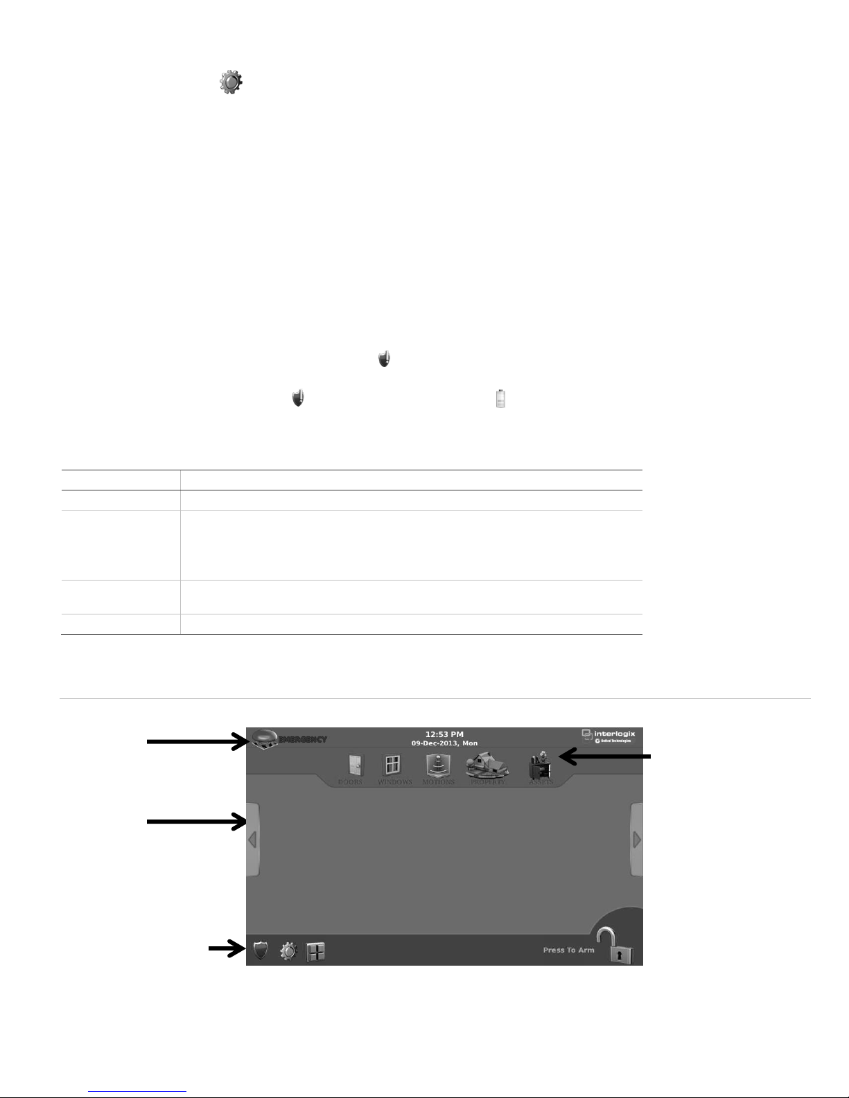
Top Bar
The Emergency Button, Time
and Date, and Dealer
Information.
Folder
Displays application and alarm
information.
Bottom Bar
Provides access to system
status, settings, applications,
and arming options.
At-A-Glance Icons
Provides sensor status for all
monitored Doors, Windows,
Motions, Property, and Assets.
Checking Battery Status (after initialization)
1. Press the Settings icon on the lower left of the main screen.
2. Press CONFIGURATION to enter programming.
3. Enter the installer or dealer access code (see table 5).
4. From the Configuration & Programming screen, press TEST.
5. From the Test screen, press BATTERY.
6. To start the battery test, press START. The results are displayed after the battery test is complete.
Initialization
When power is first applied (and if the panel was not previously initialized), an initial screen appears. This screen is part of the
installation wizard startup sequence. The wizard runs only one time at installation (unless the system has been reinstalled).
The wizard startup sequence provides a series of prompts. Each prompt requires a response before moving to the next. See Table 3
for a description of the initial power up screen prompts.
Upon initial installation, the system will check the backup battery. If the battery is low, it may take up to 48 hours to become fully
charged. During this time, a system-status-attention icon will be shown on the main screen and trouble beeps will occur until the
battery is sufficiently charged.
Press the System Status Attention icon to verify that the Low Battery icon is present on the system status screen. After the
battery is charged, if the panel loses AC Power and experiences a low battery condition, the low battery icon will appear and trouble
beeps will sound unless silenced.
Table 3: Initial Power Up Screens
Main Screen
Upon successful completion of initialization, the main screen will be displayed. See Figure 5.
Figure 5: AdvisorOne Main Screen
AdvisorOne Panel Quick Installation Guide 5 / 18

Icon
Description
System Status - Press this icon to access the System Status, Sensor Status, and Events Status screens.
System Status Attention - This indicates that a recent system status change has occurred or attention is required. Press the icon to
view the status.
Settings and Configuration - Press this icon to access the General settings, Display, Sound, Date & Time, Applications, and
Configuration screens.
Applications - Press this icon to gain quick access to the applications in the system.
Disarmed - Pressing this icon will begin the sequence of ARMING the system.
Note: When disarmed, only 24-hour sensors (smoke, carbon monoxide detectors, etc.) remain active.
Function
Default
Description
Dealer Code
4322
The default privilege level is the same as the installer code (see below). Use this code only if required when Dealer Lock has
been enabled and access to the dealer-protected programming options is required.
Installer Code
4321
Use this code to configure all programming features of the panel, except those that are dealer protected when Dealer Lock
has been enabled. These options can be accessed from the Configuration & Programming menu: Devices, Users,
Communications, System Options, Testing, Administration, etc. Dealer and installer codes should be changed.
Master Code
1234
Use the master code to arm/disarm the system and to enter user programming and bypass sensors.
User Codes
Blank
Use the user code to arm/disarm the system.
Duress Code
Blank
Use the duress code to arm/disarm the system. Use of the duress code will cause a silent alarm.
The icons located on the Bottom Bar are very important in completing the installation process. These icons are described in Table 4.
Table 4: Main Screen Bottom Bar Icons
System Programming and Configuration
The AdvisorOne panel provides the main processing unit for all system functions. The programming of system options and features is
menu-driven. Access is managed by codes. Interlogix recommends the following standard programming sequence: learn sensors, add
users, configure communications, configure system options, and configure applications. Table 5 below describes the programming and
access code options.
Notes:
• Access and System Programming & Configuration options depend on what code is entered.
• When prompted for an access code, the panel will automatically exit the Access Code screen after one minute of inactivity if no
access code has been entered.
• After an access code has been entered to access the Configuration & Programming system options, the panel will automatically
return to the main screen after a period of inactivity. This period of inactivity is programmable. The default setting is ten minutes.
Table 5: Access Codes
The system supports 250 access codes.
Entering the Settings and Configuration Screen
1. Press the Settings icon on the lower left of the main screen.
2. Press CONFIGURATION to enter programming.
3. Enter the installer code or dealer code.
Configuring a Hardwired or Wireless Sensor
When configuring a hardwired or wireless sensor, refer to the specific sensors installation instructions for complete operation and
testing details.
1. From the Configuration & Programming screen, press DEVICES.
2. From the Devices screen, press EDIT next to Sensors.
3. From the Sensors screen, press TX ID or LEARN RF for wireless sensors or press Add HW for hardwired sensors.
6 / 18 AdvisorOne Panel Quick Installation Guide
 Loading...